EP2511412A2 - Waschmaschine und Verfahren zu ihrer Steuerung - Google Patents
Waschmaschine und Verfahren zu ihrer Steuerung Download PDFInfo
- Publication number
- EP2511412A2 EP2511412A2 EP12163624A EP12163624A EP2511412A2 EP 2511412 A2 EP2511412 A2 EP 2511412A2 EP 12163624 A EP12163624 A EP 12163624A EP 12163624 A EP12163624 A EP 12163624A EP 2511412 A2 EP2511412 A2 EP 2511412A2
- Authority
- EP
- European Patent Office
- Prior art keywords
- phase
- turbulence
- inner drum
- drum
- rotational speed
- Prior art date
- Legal status (The legal status is an assumption and is not a legal conclusion. Google has not performed a legal analysis and makes no representation as to the accuracy of the status listed.)
- Granted
Links
Images




Classifications
-
- D—TEXTILES; PAPER
- D06—TREATMENT OF TEXTILES OR THE LIKE; LAUNDERING; FLEXIBLE MATERIALS NOT OTHERWISE PROVIDED FOR
- D06F—LAUNDERING, DRYING, IRONING, PRESSING OR FOLDING TEXTILE ARTICLES
- D06F35/00—Washing machines, apparatus, or methods not otherwise provided for
- D06F35/005—Methods for washing, rinsing or spin-drying
- D06F35/006—Methods for washing, rinsing or spin-drying for washing or rinsing only
-
- D—TEXTILES; PAPER
- D06—TREATMENT OF TEXTILES OR THE LIKE; LAUNDERING; FLEXIBLE MATERIALS NOT OTHERWISE PROVIDED FOR
- D06F—LAUNDERING, DRYING, IRONING, PRESSING OR FOLDING TEXTILE ARTICLES
- D06F37/00—Details specific to washing machines covered by groups D06F21/00 - D06F25/00
- D06F37/02—Rotary receptacles, e.g. drums
- D06F37/04—Rotary receptacles, e.g. drums adapted for rotation or oscillation about a horizontal or inclined axis
- D06F37/06—Ribs, lifters, or rubbing means forming part of the receptacle
- D06F37/065—Ribs, lifters, or rubbing means forming part of the receptacle ribs or lifters having means for circulating the washing liquid
Definitions
- the invention relates to a washing machine, for example a commercial washing machine or a household washing machine, comprising a fixed outer drum and an inner drum arranged in the outer drum, which can be driven by a drive in rotation relative to the outer drum, and a controller which controls the drive during a washing operation, that it rotates the inner drum in opposite directions of rotation, wherein the inner drum undergoes at least one rotation cycle in a rotational movement in each of the directions of rotation, which comprises an acceleration phase, a Wäschumicalzphase and a deceleration phase.
- a washing machine for example a commercial washing machine or a household washing machine, comprising a fixed outer drum and an inner drum arranged in the outer drum, which can be driven by a drive in rotation relative to the outer drum, and a controller which controls the drive during a washing operation, that it rotates the inner drum in opposite directions of rotation, wherein the inner drum undergoes at least one rotation cycle in a rotational movement in each of the directions of rotation, which comprises an acceleration phase, a W
- washing machines are known from the prior art, but in these there is no optimal utilization of the wash liquor, so that the existing volume of the wash liquor is not optimally utilized.
- the invention is therefore an object of the invention to improve a washing machine of the generic type such that an improved utilization of the wash liquor is possible, so that the volume of the wash liquor can be reduced based on a predetermined amount of laundry.
- the controller can pass through the inner drum during the Wäschumubalzphase at least one turbulence phase in which a rotational speed of the inner drum by more than 5% of averaging over the entire Wäschumcielzphase averaging the Rotation speed deviates.
- the advantage of the solution according to the invention is that with the introduction of such turbulence phases it is possible to improve the flow of the laundry and thus make optimal use of the existing wash liquor.
- the duration of the turbulence phase can be determined such that it lasts in particular a maximum of 4 seconds.
- the turbulence phase lasts for a maximum of 3 seconds, and it is optimal if the turbulence phase lasts for a maximum of 2 seconds.
- the turbulence phase has a maximum duration which does not exceed 20% of the duration of the Wäschum stiilzphase, even better 10% of the duration and optionally 5% of the duration of the Wäschumianulzphase, that is, therefore smaller is one-fifth, even better one-tenth, and possibly one-twentieth of the duration of the laundry circulation phase.
- controller controls the drive in such a way that several turbulence phases occur during the laundry circulation phase.
- each turbulence phase comprises a deceleration phase and a subsequent acceleration phase of the inner drum or an acceleration phase and a subsequent deceleration phase of the inner drum.
- Between the deceleration phase and acceleration phase can still be a phase of a constant rotational speed or just a maximum of the rotational speed.
- the turbulence phases follow one another in such a way that the acceleration phase of one turbulence phase directly merges into the acceleration phase of the subsequent turbulence phase and the deceleration phase of one turbulence phase likewise directly merges into the deceleration phase of the subsequent turbulence phase.
- a radial distance between an outer wall surface of the inner drums and an inner surface of the outer drum is formed in a circumferential direction varying, that is, that the space between the outer wall surface of the inner drum and the inner surface of the Outside drum seen in the direction of rotation varies.
- Such a varying intermediate space can be realized, for example, in that the inner drum has an outer wall surface that varies radially with respect to the axis of rotation.
- outer drum has radially narrowed inner wall areas.
- Such radially narrowed inner wall regions can be arranged at various points of the outer drum.
- the radially narrowed inner wall areas are located within a lower outer drum segment which extends over an angle range of maximum 120 ° on both sides of a point of the outer drum which is at a lowermost position with respect to the direction of gravity.
- the radially narrowed inner wall regions lie in an angular range W of between 40 ° and 140 °, starting from the point of the outer drum which is at a low point in the direction of gravity.
- the radially narrowed inner wall regions are in an angular range of 60 ° to 120 °, starting from the lowest point.
- the radially narrowed inner wall areas can now be realized in various ways.
- a particularly favorable solution provides that the radially narrowed inner wall regions are formed by a cross-sectional shape deviating from a circular cross-sectional area of the inner surface of the outer drum.
- the radially narrowed inner wall regions are formed by an elliptical cross-sectional area of the inner surface of the outer drum.
- the inner drum is designed so that it has an outer wall surface with a circular cross-sectional shape.
- the inner drum is provided with radially over an inner wall surface inwardly projecting Schöpfrippen, wherein the scooping ribs have internal spaces for receiving and entraining washing water of the wash liquor.
- a method for washing laundry with a washing machine comprising a fixed outer drum and an inner drum arranged in the outer drum, which is driven by a drive rotating relative to the outer drum, wherein during a washing operation, the inner drum in opposite directions of rotation rotates and the inner drum during a rotational movement in each of the directions of rotation passes through at least one rotation cycle, the acceleration phase, a Wäschummélzphase and comprises a deceleration phase, and wherein the inner drum during the Wäschumisselzphase undergoes at least one turbulence phase in which a rotational speed of the inner drum deviates by more than 5% from averaging over the entire Wäschumubalzphase average of the rotational speed.
- a further advantageous embodiment provides that in each turbulence phase, the rotational speed does not fall below a minimum value of 10% of the mean value.
- a preferred embodiment provides that each turbulence phase lasts a maximum of 4 seconds.
- each turbulence phase lasts a maximum of 3 seconds.
- each turbulence phase has a maximum duration that does not exceed 20% of the duration of the Wäschumskylzphase.
- an embodiment is advantageous in which several turbulence phases occur during the wash circulation phase.
- each turbulence phase comprises a deceleration phase and a subsequent acceleration phase of the inner drum or an acceleration phase and a subsequent deceleration phase of the inner drum.
- An in Fig. 1 to 3 schematically illustrated washing machine 10 comprises a machine frame 12, on which an outer drum 14 is mounted, for example by means of spring-mounted bearings 16 about an initial position elastically resiliently movable.
- the outer drum 14 in this case comprises an outer drum jacket 20 which is closed at the rear by an outer drum rear wall 22 and is closed at the front by an outer drum front wall 24, through whose door an interior 26 of the outer drum 14 is accessible.
- FIG. 3 is shown in the outer drum 14 as a whole with 30 designated inner drum rotatably mounted a rotation axis 32, wherein a pivot bearing 33 (FIG. Fig. 2 ) is arranged on the outer drum rear wall 22 for the inner drum 30.
- the inner drum 30 is relative to the outer drum 14 by a drive 34 (FIG. Fig. 1 to 3 ), which is fixed relative to the outer drum 14 and thus in the case of the elastically resilient bearings 16 together with the outer drum 14 is movable relative to the machine frame 12.
- the inner drum 30 has an apertured inner drum shell 36, which has, for example, a circular in cross-section outer wall surface 38.
- scoop ribs 40 are further arranged, which protrude from an inner wall surface 42 of the inner drum shell 36 radially inwardly in the direction of the axis of rotation 32 and are hollow to form an inner space 44 inside, so that the scoop ribs 40 are capable of washing water when they submerge a wash liquor 50 which accumulates in a lower region of the outer drum 14 ( Fig. 3 and 4 ).
- the scoop ribs 40 are formed as a cross-sectionally triangular hollow body with perforated wall portions 48, so that when dipping the scoop ribs 40 in the wash liquor 50, the scoop ribs 40 can fill with wash water, which is when the scoop ribs 40 from the wash liquor 50 by turning emerge from the inner drum 30, in turn emptied from the scooping ribs 40 on the arranged in the inner drum laundry.
- the outer drum shell 20 is, as in Fig. 1 and 2 illustrated, closed and formed liquid-tight, so that he holds the wash liquor 50.
- heating elements HZ are provided between the outer drum 14 and the inner drum 30 in a lower region.
- the outer drum shell 20 has an inner surface 52, which in a circumferential direction 54 has a varying radial distance RA from the outer wall surface 38 of the inner drum 30.
- the outer drum 14 forms on both sides of a defined by the direction of gravity deepest point 56 of the outer drum 14 has a lower inner wall portion 58 which extends at a constant radial distance RA from the outer wall surface 38 of the inner drum 30, and then merges with the inner wall portion 58 in a radially narrowed inner wall portion 62 whose distance from the outer wall surface 38 of the inner drum 30 varies in the circumferential direction 54 and varies from a distance RA MAX corresponding to the lower inner wall portion 58 to a minimum distance RA MIN .
- the radially narrowed inner wall regions 62 preferably lie, starting from the lowest point 56, within a lower outer drum segment 60, which extends over a maximum angle range WAS of 120 ° on both sides of the lowest point 56.
- the radially narrowed inner wall region 62 can be achieved, for example, by inserting bodies 64 extending in a circular cross-section parallel to the axis of rotation 32 on the one hand against the outer drum shell 20 and on the other hand having an inner side 66 which, for example, is in the form of a secant to the circular in cross-section shape of the outer drum wall 20 extends.
- the body 64 with an inner side 66 which has a curvature rising in the direction of the axis of rotation 32.
- the bodies 64 are arranged with the inside 66 forming the radially narrowed inner wall portion 62 so that the radially narrowed inner wall portion 62 extends from the lowest point 56 in an angular range W of 80 ° to 100 ° relative to the axis of rotation 32.
- the radial distance RA between the outer wall surface 38 of the inner drum 30 and the inner surface 52 of the outer drum shell 20 varies from the lowest point 56 in the circumferential direction 54, particularly in an angular range W of 80 ° to 100 ° with respect to the rotational axis 32 , wherein the bodies 64 are arranged symmetrically to the axis of rotation 32 on the outer drum shell 20.
- the radially narrowed inner wall regions 62 of the outer drum 14 make it possible for the proportion of the wash liquor 50, which is also referred to as a dead liquor, to be present in a gap Z between the outer wall surface 38 of the inner drum 30 and the inner surface 52 of the outer drum 14 since it does not contribute to the washing process, to reduce, namely by reducing the volume of the wash liquor 50 in total, without affecting the washing performance, since the portion of the dead liquor entrained in a rotational movement of the inner drum 30 in the respective direction of rotation 70 by the radially narrowed inner wall portions 62 into the interior of the inner drum 30 is pressed and thus involved in the washing process.
- a controller designated as a whole by 80 is provided, which controls the various functions of the washing machine 10, but in particular controls the movement of the inner drum 30 by the drive 34 in connection with the other functions of the washing machine.
- the drive of the drive 34 via a fast-clocking frequency converter 82, so that changes in the rotational speed of the inner drum 30 can be realized with high dynamics.
- controller 80 for the drive 34 of the inner drum 30 can this, such as in Fig. 2 shown in opposite directions of rotation 70L (clockwise) and 70R (clockwise) rotate about the axis of rotation 32, wherein in each of the directions of rotation 70L and 70R, the inner drum 30 undergoes a rotational cycle DZ, such as in Fig.
- an acceleration phase BP, a Wäschum stiilzphase WP and a braking phase includes AP, wherein in the acceleration phase BP increases the rotational speed, ie the angular velocity with respect to the rotation about the axis of rotation 32, starting from the value zero, in the Wäschumisselzphase WP the rotational speed remains constant and in the deceleration phase AP, the rotational speed is again reduced to the value zero, so that each rotational cycle DZ starts at the rotational speed zero and ends at the rotational speed zero.
- a rest cycle RZ is provided between two rotational cycles DZ, in which the rotational speed is zero, before a rotation in the opposite direction of rotation 70 takes place.
- turbulence phase TP preferably a plurality of turbulence phases TP1 to TP11, occurs in which, based on a over the entire period of the Wäschumisselzphase WP by averaging average value M of the rotational speed, the rotational speed of the inner drum 30th is varied by deviating from this mean value M, in such a way that each of the turbulence phases TP has at least one acceleration phase TBP and one deceleration phase TVP, between which a turbulence value TW deviating maximally from this mean value M is present.
- the turbulence value TW attained during the turbulence phases TP can deviate from the mean value M by more than 5%, preferably more than 10% and even better more than 20% and in particular more than 30%, so that the turbulence values TW that occur during the individual combustion Turbulence phases TP, reaching maximum values which are greater than the mean value M or smaller than the mean value M by the above-mentioned values, wherein preferably during the occurrence of the turbulence phases TP the rotational speed does not become zero but has a minimum value which amounts to 10%. of the mean does not fall below 20% of the mean value.
- the durations during which the individual turbulence phases TP occur are less than 4 seconds per turbulence phase TP, more preferably less than 3 seconds, and preferably less than 2 seconds, that is, the turbulence phases TP are short relative to the laundry recirculation phases WP.
- the durations of the turbulence phases TP are less than one-fifth, more preferably less than one-tenth of the duration of the laundry recirculation phase WP.
- the wash liquor 50 is put into turbulent flows, which increases the flow of the laundry and improves the washing effect.
- the controller 80 is designed, for example, such that the rotational speed cycles DZ with the acceleration phases BP, the Wäschumcielzphasen WP together with the turbulence phases TP and subsequent braking phases AP are stored as a fixed sequence with fixed amplitudes and durations in one or in variations in several programs, which are processed by the controller 80, wherein a machine operator can select, for example, one of the programs depending on the type of laundry.
- the controller 80 may also be designed such that it can control the rotational cycles DZ and / or the acceleration phases BP and / or the turbulence phases TP and / or the deceleration phases AP to the conditions prevailing in the inner drum 30 and the outer drum 14, depending on the type and adjusting the amount of laundry, wherein the adjustment is made by interrogation of specifications that can be entered by a machine operator in the program selection, and / or by interrogation of sensors that detect the conditions in the inner drum 30 and the outer drum 14 and the sensor values of the Transmit control 80.
- the controller 80 may operate with fixed acceleration phases BP, predetermined wash circulation phases WP, and predetermined braking phases AP and adaptively determine the turbulence phases TP only during the wash circulation phases WP in number, duration, and amplitude, for example by loading the internal drum 30, for example by means of a the pivot bearing 33 associated weight sensor 90 or the bearings 16 associated weight sensors 92, and the filling height of the wash liquor 50, for example by means of the outer drum 14 associated level sensor 94, in particular also with regard to their fluctuations during the rotation cycles, can be detected, for example, the number determine required turbulence phases TP per Wäschumklalzhase WP and / or determine their duration and / or amplitude.
- the radially narrowed inner wall portions 62 'of the outer drum 14' are formed directly by the outer drum shell 20 having an elliptical cross-sectional area such that the distance RA continuously changes from the value R MAX to the value R MIN .
Landscapes
- Engineering & Computer Science (AREA)
- Textile Engineering (AREA)
- Control Of Washing Machine And Dryer (AREA)
Abstract
Description
- Die Erfindung betrifft eine Waschmaschine, beispielsweise eine gewerbliche Waschmaschine oder eine Haushaltswaschmaschine, umfassend eine feststehende Außentrommel und eine in der Außentrommel angeordnete Innentrommel, die durch einen Antrieb rotierend relativ zur Außentrommel antreibbar ist, sowie eine Steuerung, welche während eines Waschvorgangs den Antrieb derart ansteuert, dass dieser die Innentrommel in entgegengesetzten Drehrichtungen dreht, wobei die Innentrommel bei einer Drehbewegung in jeder der Drehrichtungen mindestens einen Drehzyklus durchläuft, der eine Beschleunigungsphase, eine Wäscheumwälzphase und eine Abbremsphase umfasst.
- Derartige Waschmaschinen sind aus dem Stand der Technik bekannt, bei diesen findet allerdings keine optimale Ausnutzung der Waschflotte statt, so dass das vorhandene Volumen der Waschflotte nicht optimal ausgenützt wird.
- Der Erfindung liegt daher die Aufgabe zugrunde, eine Waschmaschine der gattungsgemäßen Art derart zu verbessern, dass eine verbesserte Ausnutzung der Waschflotte möglich ist, so dass das Volumen der Waschflotte bezogen auf eine vorgegebene Wäschemenge reduziert werden kann.
- Diese Aufgabe wird bei einer Waschmaschine der eingangs beschriebenen Art erfindungsgemäß dadurch gelöst, dass die Steuerung die Innentrommel während der Wäscheumwälzphase mindestens eine Turbulenzphase durchlaufen lässt, in der eine Drehgeschwindigkeit der Innentrommel um mehr als 5% von einem durch Mittelung über die gesamte Wäscheumwälzphase ermittelnden Mittelwert der Drehgeschwindigkeit abweicht.
- Der Vorteil der erfindungsgemäßen Lösung ist darin zu sehen, dass mit der Einführung derartigen Turbulenzphasen die Möglichkeit geschaffen wird, die Durchflutung der Wäsche zu verbessern und somit die vorhandene Waschflotte optimal auszunutzen.
- Insbesondere besteht dabei die Möglichkeit bei einer vorgegebenen Wäschemenge das Volumen der Waschflotte zu reduzieren und somit Vorteile hinsichtlich des Wasserverbrauchs, des Waschmittelverbrauchs, des Energieverbrauchs der Waschmaschine zum Aufheizen der Waschflotte somit der Umweltverträglichkeit zu erreichen.
- Besonders günstig ist es, wenn in der Turbulenzphase die Drehgeschwindigkeit der Innentrommel um mehr als 10% von dem Mittelwert abweicht.
- Noch besser ist es, wenn in der Turbulenzphase die Drehgeschwindigkeit der Innentrommel um mehr als 20% von dem Mittelwert abweicht und besonders bevorzugt ist eine Lösung, bei welcher in der Turbulenzphase die Drehgeschwindigkeit der Innentrommel um mehr als 30% von dem Mittelwert abweicht.
- Besonders günstig ist eine Ausführung, bei welcher in der Turbulenzphase die Drehgeschwindigkeit einen Minimalwert von 10% des Mittelwerts nicht unterschreitet, so dass jeweils in der jeweiligen Drehrichtung stets noch eine Drehung mit einer nennenswerten Drehgeschwindigkeit in dieser Drehrichtung erfolgt.
- Noch besser ist es, wenn in jeder Turbulenzphase die Drehgeschwindigkeit einen Minimalwert von 20% des Mittelwerts nicht unterschreitet.
- Hinsichtlich der Zeitdauer der Turbulenzphase wurden bislang noch keine näheren Angaben gemacht.
- So kann in Absolutwerten die Zeitdauer der Turbulenzphase dahingehend festgelegt werden, dass diese insbesondere maximal 4 Sekunden dauert.
- Noch vorteilhafter ist es, wenn die Turbulenzphase maximal 3 Sekunden dauert und optimal ist es, wenn die Turbulenzphase maximal 2 Sekunden dauert.
- Darüberhinaus ist eine relative Angabe der Zeitdauer der Turbulenzphase dadurch möglich, dass die Turbulenzphase eine maximale Dauer hat, die 20% der Dauer der Wäscheumwälzphase, noch besser 10% der Dauer und gegebenenfalls 5% der Dauer der Wäscheumwälzphase, nicht überschreitet, das heißt also kleiner ist als ein Fünftel, noch besser ein Zehntel und gegebenenfalls ein Zwanzigstel der Dauer der Wäscheumwälzphase.
- Besonders günstig ist es, wenn die Steuerung den Antrieb derart steuert, dass während der Wäscheumwälzphase mehrere Turbulenzphasen auftreten.
- Insbesondere ist günstigerweise vorgesehen, dass jede Turbulenzphase eine Verzögerungsphase und eine nachfolgende Beschleunigungsphase der Innentrommel oder eine Beschleunigungsphase und eine nachfolgende Verzögerungsphase der Innentrommel umfasst.
- Zwischen Verzögerungsphase und Beschleunigungsphase kann noch eine Phase einer konstanten Drehgeschwindigkeit liegen oder lediglich ein Maximum der Drehgeschwindigkeit.
- Besonders günstig ist es dabei insbesondere, wenn die Turbulenzphasen so aufeinanderfolgen, dass die Beschleunigungsphase der einen Turbulenzphase in die Beschleunigungsphase der nachfolgenden Turbulenzphase unmittelbar übergeht und die Verzögerungsphase der einen Turbulenzphasen ebenfalls unmittelbar in die Verzögerungsphase der nachfolgenden Turbulenzphase übergeht.
- Darüberhinaus wird die eingangs genannte Aufgabe erfindungsgemäß alternativ oder ergänzend auch dadurch gelöst, dass ein radialer Abstand zwischen einer Außenwandfläche der Innentrommeln und einer Innenfläche der Außentrommel in einer Umlaufrichtung variierend ausgebildet ist, das heißt, dass der Zwischenraum zwischen der Außenwandfläche der Innentrommel und der Innenfläche der Außentrommel in Umlaufrichtung gesehen variiert.
- Ein derartiger variierender Zwischenraum kann beispielsweise dadurch realisiert sein, dass die Innentrommel eine Außenwandfläche hat, die radial zur Drehachse variiert.
- Eine besonders vorteilhafte Möglichkeit sieht jedoch vor, dass die Außentrommel radial verengte Innenwandbereiche aufweist.
- Derartige radial verengte Innenwandbereiche können an verschiedensten Stellen der Außentrommel angeordnet sein.
- Besonders günstig ist es, wenn die radial verengten Innenwandbereiche innerhalb eines unteren Außentrommelsegments liegen, das sich zu beiden Seiten eines bezogen auf die Schwerkraftrichtung tiefstliegenden Punktes der Außentrommel über einen Winkelbereich von maximal 120° erstreckt.
- Besonders günstig ist es, wenn radial verengten Innenwandbereiche auf einander gegenüberliegenden Seiten der Außentrommel liegen.
- Insbesondere ist es günstig, wenn die radial verengten Innenwandbereiche ausgehend von dem in Schwerkraftrichtung tiefstliegenden Punkt der Außentrommel in einem Winkelbereich W zwischen 40° und 140° liegen.
- Besonders günstig ist es, wenn die radial verengten Innenwandbereiche ausgehend vom tiefsten Punkt in einem Winkelbereich von 60° bis 120° liegen. Die radial verengten Innenwandbereiche lassen sich nun in unterschiedlichster Art und Weise realisieren.
- Beispielsweise wäre es denkbar, an der Außentrommel auf einer Innenseite über die Innenfläche vorstehende Rippen vorzusehen.
- Eine besonders günstige Lösung sieht vor, dass die radial verengten Innenwandbereiche durch eine von einer kreisrunden Querschnittsfläche abweichende Querschnittsform der Innenfläche der Außentrommel gebildet sind.
- Beispielsweise ist dies dadurch möglich, dass die radial verengten Innenwandbereiche durch eine elliptische Querschnittsfläche der Innenfläche der Außentrommel gebildet sind.
- Im einfachsten Fall ist dabei die Innentrommel so ausgebildet, dass sie eine Außenwandfläche mit einer kreisrunden Querschnittsform aufweist.
- Ferner ist zur Verbesserung der Durchflutung der Wäsche noch vorgesehen, dass die Innentrommel mit radial über eine Innenwandfläche nach innen überstehenden Schöpfrippen versehen ist, wobei die Schöpfrippen Innenräume zur Auf- und Mitnahme von Waschwasser der Waschflotte aufweisen.
- Die eingangs genannte Aufgabe wird erfindungsgemäß außerdem durch ein Verfahren zum Waschen von Wäsche mit einer Waschmaschine, umfassend eine feststehende Außentrommel und eine in der Außentrommel angeordnete Innentrommel, die durch einen Antrieb rotierend relativ zur Außentrommel angetrieben wird, wobei während eines Waschvorgangs die Innentrommel in entgegengesetzten Drehrichtungen dreht und die Innentrommel bei einer Drehbewegung in jeder der Drehrichtungen mindestens einen Drehzyklus durchläuft, der eine Beschleunigungsphase, eine Wäscheumwälzphase und eine Abbremsphase umfasst, und wobei die Innentrommel während der Wäscheumwälzphase mindestens eine Turbulenzphase durchläuft, in der eine Drehgeschwindigkeit der Innentrommel um mehr als 5% von einem durch Mittelung über die gesamte Wäscheumwälzphase ermittelnden Mittelwert der Drehgeschwindigkeit abweicht.
- Noch vorteilhafter ist es, wenn in der Turbulenzphase die Drehgeschwindigkeit der Innentrommel um mehr als 10% noch besser mehr als 20% von dem Mittelwert abweicht.
- Besonders günstig ist es, wenn in der Turbulenzphase die Drehgeschwindigkeit der Innentrommel um mehr als 30% von dem Mittelwert abweicht.
- Eine weitere vorteilhafte Ausführungsform sieht vor, dass in jeder Turbulenzphase die Drehgeschwindigkeit einen Minimalwert von 10% des Mittelwerts nicht unterschreitet.
- Gegebenenfalls noch günstiger ist es, wenn in jeder Turbulenzphase die Drehgeschwindigkeit einen Minimalwert von 20% des Mittelwerts nicht unterschreitet.
- Eine bevorzugte Ausführungsform sieht vor, dass jede Turbulenzphase maximal 4 Sekunden dauert.
- Noch vorteilhafter ist es, wenn jede Turbulenzphase maximal 3 Sekunden dauert.
- Bei einer Ausführungsform ist vorgesehen, dass jede Turbulenzphase eine maximale Dauer hat, die 20% der Dauer der Wäscheumwälzphase nicht überschreitet.
- Insbesondere ist eine Ausführungsform von Vorteil, bei welcher während der Wäscheumwälzphase mehrere Turbulenzphasen auftreten.
- Eine zweckmäßige Lösung sieht vor, dass jede Turbulenzphase eine Verzögerungsphase und eine nachfolgende Beschleunigungsphase der Innentrommel oder eine Beschleunigungsphase und eine nachfolgende Verzögerungsphase der Innentrommel umfasst.
- Weitere Merkmale und Vorteile sind Gegenstand der nachfolgenden Beschreibung sowie der zeichnerischen Darstellung einiger Ausführungsbeispiele:
- In der Zeichnung zeigen:
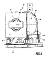
- Fig. 1
- eine schematische perspektivische Ansicht von vorne eines ersten Ausführungsbeispiels einer erfindungsgemäßen Waschmaschine;
- Fig. 2
- eine schematische perspektivische Ansicht des ersten Ausführungsbeispiels von hinten;
- Fig. 3
- eine Ansicht ähnlich
Fig. 1 von Außentrommel und Innentrommel des ersten Ausführungsbeispiels; - Fig. 4
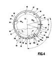
- eine Draufsicht in Richtung des Pfeils A in
Fig. 3 ; - Fig. 5
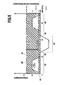
- eine schematische Darstellung von Drehzyklen der Innentrommel beim Waschvorgang;
- Fig. 6
- eine schematische Darstellung ähnlich
Fig. 5 von erfindungsgemäß verbesserten Drehzyklen der Innentrommel bei einem Waschvorgang; - Fig. 7
- eine ausschnittsweise vergrößerte Darstellung eines Drehzyklus mit Turbulenzzyklen;
- Fig. 8
- eine Darstellung ähnlich
Fig. 4 eines zweiten Ausführungsbeispiels. - Eine in
Fig. 1 bis 3 schematisch dargestellte erfindungsgemäße Waschmaschine 10 umfasst ein Maschinengestell 12, an welchem eine Außentrommel 14 beispielsweise mittels gefederten Lagerungen 16 um eine Ausgangslage elastisch federnd bewegbar gelagert ist. - Die Außentrommel 14 umfasst dabei einen Außentrommelmantel 20 welcher rückseitig durch eine Außentrommelrückwand 22 verschlossen ist und frontseitig durch eine Außentrommelfrontwand 24 verschlossen ist, über deren Türe ein Innenraum 26 der Außentrommel 14 zugänglich ist.
- Wie in
Fig. 3 dargestellt, ist in der Außentrommel 14 eine als Ganzes mit 30 bezeichnete Innentrommel eine Drehachse 32 drehbar gelagert, wobei ein Drehlager 33 (Fig. 2 ) für die Innentrommel 30 an der Außentrommelrückwand 22 angeordnet ist. - Die Innentrommel 30 ist dabei relativ zur Außentrommel 14 durch einen Antrieb 34 (
Fig. 1 bis 3 ) antreibbar, welcher relativ zur Außentrommel 14 fixiert ist und somit im Fall der elastisch federnden Lagerungen 16 mitsamt der Außentrommel 14 relativ zum Maschinengestell 12 bewegbar ist. - Wie insbesondere auch in
Fig. 4 dargestellt, hat die Innentrommel 30 einen mit Durchbrüchen versehenen Innentrommelmantel 36, welcher beispielsweise eine im Querschnitt kreisrunde Außenwandfläche 38 aufweist. - An dem Innentrommelmantel 36 sind ferner sogenannte Schöpfrippen 40 angeordnet, die von einer Innenwandfläche 42 des Innentrommelmantels 36 radial nach innen in Richtung der Drehachse 32 überstehen und unter Bildung eines Innenraums 44 innen hohl ausgebildet sind, so dass die Schöpfrippen 40 in der Lage sind, Waschwasser dann aufzunehmen, wenn diese eine Waschflotte 50 eintauchen, die sich in einem unteren Bereich der Außentrommel 14 ansammelt (
Fig. 3 und4 ). - Hierzu sind beispielsweise die Schöpfrippen 40 als im Querschnitt dreieckförmige Hohlkörper mit perforierten Wandbereichen 48 ausgebildet, so dass beim Eintauchen der Schöpfrippen 40 in die Waschflotte 50 sich die Schöpfrippen 40 mit Waschwasser füllen können, was dann, wenn die Schöpfrippen 40 aus der Waschflotte 50 durch Drehen der Innentrommel 30 austreten, sich wiederum aus den Schöpfrippen 40 auf die in der Innentrommel angeordnete Wäsche entleert.
- Der Außentrommelmantel 20 ist, wie in
Fig. 1 und2 dargestellt, geschlossen und flüssigkeitsdicht ausgebildet, so dass er die Waschflotte 50 hält. - Zur Aufheizung der Waschflotte 50 sind zwischen der Außentrommel 14 und der Innentrommel 30 in einem unteren Bereich Heizelemente HZ vorgesehen.
- Ferner hat der Außentrommelmantel 20 eine Innenfläche 52, welche in einer Umlaufrichtung 54 einen variierenden radialen Abstand RA von der Außenwandfläche 38 der Innentrommel 30 aufweist.
- Beispielsweise bildet die Außentrommel 14 beiderseits eines durch die Schwerkraftrichtung definierten tiefsten Punktes 56 der Außentrommel 14 einen unteren Innenwandbereich 58, welcher in konstantem radialem Abstand RA von der Außenwandfläche 38 der Innentrommel 30 verläuft, und anschließend an den Innenwandbereich 58 in einen radial verengten Innenwandbereich 62 übergeht, dessen Abstand von der Außenwandfläche 38 der Innentrommel 30 in der Umlaufrichtung 54 variiert und von einem dem unteren Innenwandbereich 58 entsprechenden Abstand RAMAX bis zu einem minimalen Abstand RAMIN variiert.
- Die radial verengten Innenwandbereiche 62 liegen vorzugsweise ausgehend von dem tiefsten Punkt 56 in innerhalb eines unteren Außentrommelsegments 60, das sich maximal über ein Winkelbereich WAS von 120° beiderseits des tiefsten Punktes 56 erstreckt.
- Der radial verengte Innenwandbereich 62 lässt sich beispielsweise dadurch erreichen, dass in den Außentrommelmantel 20 mit kreisrundem Querschnitt sich parallel zur Drehachse 32 erstreckende Körper 64 eingesetzt sind, die einerseits an dem Außentrommelmantel 20 anliegen und andererseits eine Innenseite 66 aufweist, die beispielsweise in Form einer Sekante zur im Querschnitt kreisrunden Form der Außentrommelwand 20 verläuft.
- Es ist aber auch denkbar, die Körper 64 mit einer Innenseite 66 zu versehen, die eine sich in Richtung der Drehachse 32 erhebende Wölbung aufweist.
- Vorzugsweise sind die Körper 64 mit der den radial verengten Innenwandbereich 62 bildenden Innenseite 66 so angeordnet, dass der radial verengte Innenwandbereich 62 ausgehend vom tiefsten Punkt 56 sich in einem Winkelbereich W von 80° bis 100° bezogen auf die Drehachse 32 erstreckt.
- Somit variiert bei dem ersten Ausführungsbeispiel der radiale Abstand RA zwischen der Außenwandfläche 38 der Innentrommel 30 und der Innenfläche 52 des Außentrommelmantels 20 ausgehend vom tiefsten Punkt 56 in Umlaufrichtung 54 gesehen, insbesondere in einem Winkelbereich W von 80° bis 100° bezogen auf die Drehachse 32, wobei die Körper 64 symmetrisch zur Drehachse 32 an dem Außentrommelmantel 20 angeordnet sind.
- Die radial verengten Innenwandbereiche 62 der Außentrommel 14 ermöglichen es den in einem Zwischenraum Z zwischen der Außenwandfläche 38 der Innentrommel 30 und der Innenfläche 52 der Außentrommel 14 stehenden Anteil der Waschflotte 50, der auch als tote Flotte bezeichnet wird, da er nicht zum Waschvorgang beiträgt, zu reduzieren, nämlich durch Reduzierung des Volumens der Waschflotte 50 insgesamt, ohne die Waschleistung zu beeinträchtigen, da der bei einer Drehbewegung der Innentrommel 30 in der jeweiligen Drehrichtung 70 mitgenommene Anteil der toten Flotte durch die radial verengten Innenwandbereiche 62 ins Innere der Innentrommel 30 gedrückt wird und sich somit am Waschvorgang beteiligt.
- Zur Ansteuerung des Antriebs 34 ist eine als Ganzes mit 80 bezeichnete Steuerung vorgesehen, welche die verschiedenen Funktionen der Waschmaschine 10 steuert, insbesondere jedoch die Bewegung der Innentrommel 30 durch den Antrieb 34 im Zusammenhang mit den anderen Funktionen der Waschmaschine steuert.
- Vorzugsweise erfolgt die Ansteuerung des Antriebs 34 über einen schnelltaktenden Frequenzumformer 82, so dass Änderungen der Drehgeschwindigkeit der Innentrommel 30 mit hoher Dynamik realisierbar sind.
- Durch die Steuerung 80 für den Antrieb 34 der Innentrommel 30 lässt sich diese, wie beispielsweise in
Fig. 2 dargestellt, in entgegengesetzte Drehrichtungen 70L (Linkslauf) und 70R (Rechtslauf) um die Drehachse 32 drehen, wobei in jeder der Drehrichtungen 70L und 70R die Innentrommel 30 einen Drehzyklus DZ durchläuft der, wie beispielsweise inFig. 5 dargestellt, eine Beschleunigungsphase BP, eine Wäscheumwälzphase WP und eine Abbremsphase AP umfasst, wobei in der Beschleunigungsphase BP die Drehgeschwindigkeit, also die Winkelgeschwindigkeit bezüglich der Drehung um die Drehachse 32, ausgehend von dem Wert Null zunimmt, in der Wäscheumwälzphase WP die Drehgeschwindigkeit konstant bleibt und in der Abbremsphase AP die Drehgeschwindigkeit wiederum auf den Wert Null reduziert wird, so dass jeder Drehzyklus DZ bei der Drehgeschwindigkeit Null beginnt und bei der Drehgeschwindigkeit Null endet. - Vorzugsweise ist zwischen zwei Drehzyklen DZ noch ein Ruhezyklus RZ vorgesehen, in dem die Drehgeschwindigkeit Null ist, bevor eine Drehung in die jeweils entgegengesetzte Drehrichtung 70 erfolgt.
- Eine in
Fig. 5 dargestellte Drehbewegung mit einer in der Wäscheumwälzphase WP konstanten Drehgeschwindigkeit entspricht einem bekannten Drehzyklus DZ. - Wie in
Fig. 6 und7 dargestellt, ist bei der erfindungsgemäßen Lösung vorgesehen, dass während der Wäscheumwälzphase WP keine konstante Drehgeschwindigkeit vorliegt, wie dies im Zusammenhang mitFig. 5 dargestellt ist, sondern dass während der Wäscheumwälzphase WP mindestens eine Turbulenzphase TP, vorzugsweise eine Vielzahl von Turbulenzphasen TP1 bis TP11, auftritt in denen, bezogen auf einen über die gesamte Zeitdauer der Wäscheumwälzphase WP durch Mittelbildung ermittelnden Mittelwert M der Drehgeschwindigkeit, die Drehgeschwindigkeit der Innentrommel 30 durch Abweichen von diesem Mittelwert M variiert, und zwar so, dass jede der Turbulenzphasen TP mindestens eine Beschleunigungsphase TBP und eine Verzögerungsphase TVP aufweist, zwischen denen ein von diesem Mittelwert M maximal abweichender Turbulenzwert TW vorliegt. - Dabei können, wie bei dem in
Fig. 6 und7 dargestellten Ausführungsbeispiel, während der ganzen Wäscheumwälzphase WP aufeinanderfolgende Turbulenzphase n TP1 bis TP11 auftreten, es können aber auch nur während eines Teils der Zeitdauer der Wäscheumwälzphase WP Turbulenzphasen TP einzeln oder in zeitlichen Abständen voneinander oder aufeinanderfolgend auftreten. - Der während der Turbulenzphasen TP erreichte Turbulenzwert TW kann dabei von dem Mittelwert M um mehr als 5%, vorzugsweise mehr als 10% und noch besser mehr als 20% und insbesondere mehr als 30% abweichen, so dass die Turbulenzwerte TW, die während der einzelnen Turbulenzphasen TP erreichbar sind, Maximalwerte erreichen, die um die vorstehend genannten Werte größer sind als der Mittelwert M oder kleiner sind als der Mittelwert M, wobei vorzugsweise die Drehgeschwindigkeit während des Auftretens der Turbulenzphasen TP nicht Null wird, sondern einen Minimalwert aufweist, der 10% des Mittelwerts nicht unterschreitet, vorzugsweise 20% des Mittelwerts nicht unterschreitet.
- Ferner liegen die Zeitdauern, während welcher die einzelne Turbulenzphasen TP auftreten, bei weniger als 4 Sekunden pro Turbulenzphase TP, noch besser weniger als 3 Sekunden und vorzugsweise weniger als 2 Sekunden, das heißt, dass die Turbulenzphasen TP relativ zu den Wäscheumwälzphasen WP kurz sind.
- In Relation zu den Wäscheumwälzphasen WP betragen die Zeitdauern der Turbulenzphasen TP weniger als ein Fünftel, noch besser weniger als ein Zehntel der Zeitdauer der Wäscheumwälzphase WP.
- Durch die während der Wäscheumwälzphase WP auftretenden Turbulenzphasen TP wird die Waschflotte 50 in turbulente Strömungen versetzt, wodurch die Durchflutung des Waschguts verstärkt wird und die Waschwirkung verbessert wird.
- Ferner wird die Bildung von Turbulenzen in der Waschflotte 50 auch noch dadurch verstärkt, dass bei in der erfindungsgemäßen Waschmaschine 10, wie insbesondere in
Fig. 4 dargestellt, die in der jeweiligen Drehrichtung 70 ansteigende und von der Drehbewegung der Innentrommel 30 mitgeführte Waschflotte 50 aufgrund der radial verengten Innenwandbereiche 62 aus dem Zwischenraum Z zwischen der Außentrommel 14 und der Innentrommel 30 durch die Perforation des Innentrommelmantels 36 in einen Innenraum des Innentrommelmantels 36 gedrückt wird, wodurch eine zusätzliche und verbesserte Durchflutung der Wäsche erreicht wird. - Die Steuerung 80 ist dabei beispielsweise so ausgebildet, dass die Drehzahlzyklen DZ mit den Beschleunigungsphasen BP, den Wäscheumwälzphasen WP zusammen mit den Turbulenzphasen TP und nachfolgend den Abbremsphasen AP als feste Abfolge mit feststehenden Amplituden und Zeitdauern in einem oder in Variationen in mehreren Programmen abgespeichert sind, die von der Steuerung 80 abgearbeitet werden, wobei ein Maschinenbediener beispielsweise einzelne der Programme je nach Art der Wäsche auswählen kann.
- Alternativ kann die Steuerung 80 aber auch so ausgebildet sein, dass sie die Drehzyklen DZ und/oder die Beschleunigungsphasen BP und/oder die Turbulenzphasen TP und/oder die Abbremsphasen AP an die jeweils in der Innentrommel 30 und der Außentrommel 14 vorliegenden Verhältnisse je nach Art und Menge der Wäsche anpasst, wobei die Anpassung durch Abfrage von Vorgaben, die seitens eines Maschinenbedieners bei der Programmwahl eingegeben werden können, und /oder durch Abfrage von Sensoren erfolgt, die die Verhältnisse in der Innentrommel 30 und der Außentrommel 14 erfassen und die Sensorwerte der Steuerung 80 übermitteln.
- Beispielsweise kann die Steuerung 80 mit festen Beschleunigungsphasen BP, festgelegten Wäscheumwälzphasen WP und festgelegten Abbremsphasen AP arbeiten und lediglich adaptiv während der Wäscheumwälzphasen WP die Turbulenzphasen TP hinsichtlich deren Zahl, Zeitdauer und Amplitude festlegen, wobei hierzu zum Beispiel die Beladung der Innentrommel 30, beispielsweise mittels eines dem Drehlager 33 zugeordneten Gewichtssensors 90 oder den Lagerungen 16 zugeordneten Gewichtssensoren 92, und die Füllhöhe der Waschflotte 50, beispielsweise mittels eines der Außentrommel 14 zugeordneten Füllstandssensors 94, insbesondere auch hinsichtlich ihrer Schwankungen während der Drehzyklen, erfasst werden können, um zum Beispiel die Zahl der pro Wäscheumwälzhase WP erforderlichen Turbulenzphasen TP festzulegen und /oder deren Zeitdauer und/oder Amplitude zu bestimmen.
- Es ist aber auch denkbar, weitere oder andere Parameter erfassende Sensoren einzusetzen mit denen direkt oder indirekt die Verhältnisse in der Innentrommel 30 und/oder der Außentrommel 14 und/oder auch der Waschflotte 50 erfasst werden können.
- Bei einem zweiten Ausführungsbeispiel, dargestellt in
Fig. 8 , sind die radial verengten Innenwandbereiche 62' der Außentrommel 14' unmittelbar durch den Außentrommelmantel 20 gebildet, der eine elliptische Querschnittsfläche aufweist, so dass der Abstand RA kontinuierlich vom Wert RMAX zum Wert RMIN übergeht. - Hinsichtlich aller übrigen Merkmale wird vollinhaltlich auf die Ausführungen zum ersten Ausführungsbeispiel verwiesen.
Claims (15)
- Waschmaschine umfassend eine feststehende Außentrommel (14) und eine in der Außentrommel (14) angeordnete Innentrommel (30), die durch einen Antrieb (34) rotierend relativ zur Außentrommel (14) antreibbar ist, sowie eine Steuerung, welche während eines Waschvorgangs den Antrieb (34) derart ansteuert, dass dieser die Innentrommel (30) in entgegengesetzten Drehrichtungen (70) dreht, wobei die Innentrommel (30) bei einer Drehbewegung in jeder der Drehrichtungen (70) mindestens einen Drehzyklus (DZ) durchläuft, der eine Beschleunigungsphase (BP), eine Wäscheumwälzphase (WP) und eine Abbremsphase (AP) umfasst,
dadurch gekennzeichnet, dass die Steuerung (80) die Innentrommel (30) während der Wäscheumwälzphase (WP) mindestens eine Turbulenzphase (TP) durchlaufen lässt, in der eine Drehgeschwindigkeit der Innentrommel (30) um mehr als 5% von einem durch Mittelung über die gesamte Wäscheumwälzphase (WP) ermittelnden Mittelwert (M) der Drehgeschwindigkeit abweicht. - Waschmaschine nach Anspruch 1, dadurch gekennzeichnet, dass in der Turbulenzphase (TP) die Drehgeschwindigkeit der Innentrommel (30) um mehr als 10% von dem Mittelwert (M) abweicht.
- Waschmaschine nach einem der voranstehenden Ansprüche, dadurch gekennzeichnet, dass in der Turbulenzphase (TP) die Drehgeschwindigkeit einen Minimalwert von 10% des Mittelwerts (M) nicht unterschreitet, und dass insbesondere in jeder Turbulenzphase (TP) die Drehgeschwindigkeit einen Minimalwert von 20% des Mittelwerts (M) nicht unterschreitet.
- Waschmaschine nach einem der voranstehenden Ansprüche, dadurch gekennzeichnet, dass jede Turbulenzphase (TP) maximal 4 Sekunden dauert, und dass insbesondere jede Turbulenzphase (TP) maximal 3 Sekunden dauert.
- Waschmaschine nach einem der voranstehenden Ansprüche, dadurch gekennzeichnet, dass jede Turbulenzphase (TP) eine maximale Dauer hat, die 20% der Dauer der Wäscheumwälzphase (WP) nicht überschreitet.
- Waschmaschine nach einem der voranstehenden Ansprüche, dadurch gekennzeichnet, dass die Steuerung (80) den Antrieb (34) derart steuert, dass während der Wäscheumwälzphase (WP) mehrere Turbulenzphasen (TP) auftreten.
- Waschmaschine nach einem der voranstehenden Ansprüche, dadurch gekennzeichnet, dass jede Turbulenzphase (TP) eine Verzögerungsphase (TVP) und eine nachfolgende Beschleunigungsphase (TBP) der Innentrommel (30) oder eine Beschleunigungsphase (TBP) und eine nachfolgende Verzögerungsphase (TVP) der Innentrommel (30) umfasst.
- Waschmaschine nach einem der voranstehenden Ansprüche, dadurch gekennzeichnet, dass ein radialer Abstand (RA) zwischen einer Außenwandfläche (38) der Innentrommel (30) und einer Innenfläche (52) der Außentrommel (14) in einer Umlaufrichtung (54) variierend ausgebildet ist.
- Waschmaschine nach einem der voranstehenden Ansprüche, dadurch gekennzeichnet, dass die Innentrommel (30) mit radial über eine Innenwandfläche (42) nach innen überstehenden Schöpfrippen (40) versehen ist, und dass insbesondere die Schöpfrippen Innenräume (44) zur Auf- und Mitnahme von Waschwasser der Waschflotte (50) aufweisen.
- Verfahren zum Waschen von Wäsche mit einer Waschmaschine, umfassend eine feststehende Außentrommel (14) und eine in der Außentrommel (14) angeordnete Innentrommel (30), die durch einen Antrieb (34) rotierend relativ zur Außentrommel (14) angetrieben wird, wobei während eines Waschvorgangs die Innentrommel (30) in entgegengesetzten Drehrichtungen (70) dreht und die Innentrommel (30) bei einer Drehbewegung in jeder der Drehrichtungen (70) mindestens einen Drehzyklus (DZ) durchläuft, der eine Beschleunigungsphase (BP), eine Wäscheumwälzphase (WP) und eine Abbremsphase (AP) umfasst,
dadurch gekennzeichnet, dass die Innentrommel (30) während der Wäscheumwälzphase (WP) mindestens eine Turbulenzphase (TP) durchläuft, in der eine Drehgeschwindigkeit der Innentrommel (30) um mehr als 5% von einem durch Mittelung über die gesamte Wäscheumwälzphase (WP) ermittelnden Mittelwert (M) der Drehgeschwindigkeit abweicht. - Verfahren nach Anspruch 10, dadurch gekennzeichnet, dass in der Turbulenzphase (TP) die Drehgeschwindigkeit der Innentrommel (30) um mehr als 10% von dem Mittelwert (M) abweicht, und dass insbesondere in der Turbulenzphase (TP) die Drehgeschwindigkeit der Innentrommel (30) um mehr als 20% von dem Mittelwert (M) abweicht.
- Verfahren nach einem der Ansprüche 10 oder 11, dadurch gekennzeichnet, dass in jeder Turbulenzphase (TP) die Drehgeschwindigkeit einen Minimalwert von 10% des Mittelwerts (M) nicht unterschreitet, und dass insbesondere in jeder Turbulenzphase (TP) die Drehgeschwindigkeit einen Minimalwert von 20% des Mittelwerts (M) nicht unterschreitet.
- Verfahren nach einem der Ansprüche 10 bis 12, dadurch gekennzeichnet, dass jede Turbulenzphase (TP) maximal 4 Sekunden dauert, und dass insbesondere jede Turbulenzphase (TP) maximal 3 Sekunden dauert.
- Verfahren nach einem der voranstehenden Ansprüche, dadurch gekennzeichnet, dass während der Wäscheumwälzphase (WP) mehrere Turbulenzphasen (TP) auftreten.
- Verfahren nach einem der Ansprüche 10 bis 14, dadurch gekennzeichnet, dass jede Turbulenzphase (TP) eine Verzögerungsphase (TVP) und eine nachfolgende Beschleunigungsphase (TBP) der Innentrommel (30) oder eine Beschleunigungsphase (TBP) und eine nachfolgende Verzögerungsphase (TVP) der Innentrommel (30) umfasst.
Applications Claiming Priority (1)
| Application Number | Priority Date | Filing Date | Title |
|---|---|---|---|
| DE102011007141A DE102011007141A1 (de) | 2011-04-11 | 2011-04-11 | Waschmaschine |
Publications (3)
| Publication Number | Publication Date |
|---|---|
| EP2511412A2 true EP2511412A2 (de) | 2012-10-17 |
| EP2511412A3 EP2511412A3 (de) | 2017-10-04 |
| EP2511412B1 EP2511412B1 (de) | 2023-11-22 |
Family
ID=46027613
Family Applications (1)
| Application Number | Title | Priority Date | Filing Date |
|---|---|---|---|
| EP12163624.5A Active EP2511412B1 (de) | 2011-04-11 | 2012-04-10 | Waschmaschine und Verfahren zu ihrer Steuerung |
Country Status (2)
| Country | Link |
|---|---|
| EP (1) | EP2511412B1 (de) |
| DE (1) | DE102011007141A1 (de) |
Cited By (2)
| Publication number | Priority date | Publication date | Assignee | Title |
|---|---|---|---|---|
| EP2725129A1 (de) * | 2012-10-26 | 2014-04-30 | Electrolux Home Products Corporation N.V. | Verfahren zur Steuerung einer Waschmaschine und Waschmaschine |
| WO2021197896A1 (de) * | 2020-03-30 | 2021-10-07 | Miele & Cie. Kg | Verfahren und waschautomat |
Families Citing this family (1)
| Publication number | Priority date | Publication date | Assignee | Title |
|---|---|---|---|---|
| DE102013106089A1 (de) * | 2013-06-12 | 2014-12-18 | Miele & Cie. Kg | Waschverfahren für eine Waschmaschine |
Family Cites Families (10)
| Publication number | Priority date | Publication date | Assignee | Title |
|---|---|---|---|---|
| DE1876017U (de) * | 1961-06-19 | 1963-07-25 | Constructa Werke G M B H | Waschmaschinen-aussentrommel. |
| DE2505917A1 (de) * | 1975-02-13 | 1976-08-26 | Licentia Gmbh | Bottich fuer eine waeschebehandlungsmaschine |
| DE3324481A1 (de) * | 1983-07-07 | 1985-01-24 | Miele & Cie GmbH & Co, 4830 Gütersloh | Waschverfahren fuer eine programmgesteuerte trommelwaschmaschine |
| JPH04276293A (ja) * | 1991-03-01 | 1992-10-01 | Toshiba Corp | ドラム式洗濯機 |
| ES2146130B1 (es) * | 1995-12-27 | 2001-02-16 | Fagor S Coop | Metodo de lavado de ropa en una lavadora domestica. |
| KR100403026B1 (ko) * | 2001-07-31 | 2003-10-23 | 삼성전자주식회사 | 세탁물의 흡수특성을 고려한 세탁기의 제어방법 |
| US6557199B2 (en) * | 2001-09-05 | 2003-05-06 | Maytag Corporation | Wash solution mixing system for clothes washing machine |
| JP3993156B2 (ja) * | 2003-10-23 | 2007-10-17 | 松下電器産業株式会社 | ドラム式洗濯機 |
| EP2075362B1 (de) * | 2007-12-27 | 2015-11-04 | Electrolux Home Products Corporation N.V. | Verbesserungen für eine Wasch- und Trocknungsmaschine für Wäsche |
| DE102010028141B4 (de) * | 2009-05-08 | 2018-11-15 | BSH Hausgeräte GmbH | Verfahren zur Behandlung von Wäsche in einer Trommelwaschmaschine unter verbesserten Schöpfbedingungen |
-
2011
- 2011-04-11 DE DE102011007141A patent/DE102011007141A1/de active Pending
-
2012
- 2012-04-10 EP EP12163624.5A patent/EP2511412B1/de active Active
Non-Patent Citations (1)
| Title |
|---|
| None |
Cited By (3)
| Publication number | Priority date | Publication date | Assignee | Title |
|---|---|---|---|---|
| EP2725129A1 (de) * | 2012-10-26 | 2014-04-30 | Electrolux Home Products Corporation N.V. | Verfahren zur Steuerung einer Waschmaschine und Waschmaschine |
| WO2014064269A1 (en) * | 2012-10-26 | 2014-05-01 | Electrolux Home Products Corporation N.V. | Method for controlling a laundry washing machine and laundry washing machine |
| WO2021197896A1 (de) * | 2020-03-30 | 2021-10-07 | Miele & Cie. Kg | Verfahren und waschautomat |
Also Published As
| Publication number | Publication date |
|---|---|
| DE102011007141A1 (de) | 2012-10-11 |
| EP2511412A3 (de) | 2017-10-04 |
| EP2511412B1 (de) | 2023-11-22 |
Similar Documents
| Publication | Publication Date | Title |
|---|---|---|
| EP2217752B1 (de) | Verfahren und vorrichtung zur bestimmung der optimalen drehzahl der trommel einer wäschebehandlungsvorrichtung | |
| DE19841245B4 (de) | Schleudervorrichtung | |
| DE602005004901T2 (de) | Wasserumwälzende Haushaltwaschmaschine mit automatischer Wäscharterfassung und dazugehörigem Verfahren | |
| DE10326551A1 (de) | Wasch- und Spülverfahren für eine Waschmaschine | |
| DE19812682B4 (de) | Trockenschleuderverfahren und Trockenschleuder | |
| EP2133455A1 (de) | Verfahren und Einrichtung zum Bestimmen von Schaum in einer Waschmaschine | |
| DE102015204540A1 (de) | Verfahren zum Betrieb einer Waschmaschine mit einem elektrochemischen Sensor sowie hierzu geeignete Waschmaschine | |
| EP2044252B1 (de) | Verfahren zur behandlung von wäsche sowie hierzu geeignete programmgesteuerte waschmaschine | |
| EP2183422B1 (de) | Verfahren zur behandlung von wäsche sowie hierzu geeignete programmgesteuerte waschmaschine | |
| EP2511412B1 (de) | Waschmaschine und Verfahren zu ihrer Steuerung | |
| DE112018001841B4 (de) | Waschmaschine | |
| EP2592182A1 (de) | Waschmaschine mit verringerter Rückbefeuchtung sowie Verfahren zu ihrem Betrieb | |
| EP2463432A1 (de) | Waschmaschine mit Wasserzufuhr über Trommelrippen | |
| EP1417369B1 (de) | Verfahren zum betreiben einer programmierbaren waschmaschine und dafür geeignete waschmaschine | |
| WO2008000591A1 (de) | Verfahren zum einbringen von waschmitteln und waschmaschine dafür | |
| DE102009029240A1 (de) | Verfahren zur Behandlung von Wäsche sowie hierzu geeignete programmgesteuerte Waschmaschine | |
| EP1350880B1 (de) | Waschmaschine mit Mitnehmer | |
| DE102008054392A1 (de) | Mitnehmer, Wäschetrommel und Waschmaschine | |
| DE102013113425A1 (de) | Waschmaschinentrommel und mit derselben durchgeführtes Waschverfahren | |
| DE112014003395T5 (de) | Trommelwaschmaschine | |
| DE102010028141B4 (de) | Verfahren zur Behandlung von Wäsche in einer Trommelwaschmaschine unter verbesserten Schöpfbedingungen | |
| EP4328373A1 (de) | Einspülschlauch für ein wasserführendes haushaltsgerät | |
| DE102011006783B4 (de) | Von vorne beschickbare Wäschepflegemaschine mit einer Manschette | |
| DE102011087258A1 (de) | Waschmaschine mit verringerter Rückbefeuchtung sowie Verfahren zu ihrem Betrieb | |
| DE102008035790B4 (de) | Trommelwaschmaschine |
Legal Events
| Date | Code | Title | Description |
|---|---|---|---|
| PUAI | Public reference made under article 153(3) epc to a published international application that has entered the european phase |
Free format text: ORIGINAL CODE: 0009012 |
|
| AK | Designated contracting states |
Kind code of ref document: A2 Designated state(s): AL AT BE BG CH CY CZ DE DK EE ES FI FR GB GR HR HU IE IS IT LI LT LU LV MC MK MT NL NO PL PT RO RS SE SI SK SM TR |
|
| AX | Request for extension of the european patent |
Extension state: BA ME |
|
| PUAL | Search report despatched |
Free format text: ORIGINAL CODE: 0009013 |
|
| AK | Designated contracting states |
Kind code of ref document: A3 Designated state(s): AL AT BE BG CH CY CZ DE DK EE ES FI FR GB GR HR HU IE IS IT LI LT LU LV MC MK MT NL NO PL PT RO RS SE SI SK SM TR |
|
| AX | Request for extension of the european patent |
Extension state: BA ME |
|
| RIC1 | Information provided on ipc code assigned before grant |
Ipc: D06F 37/06 20060101ALN20170831BHEP Ipc: D06F 33/02 20060101ALN20170831BHEP Ipc: D06F 35/00 20060101AFI20170831BHEP |
|
| STAA | Information on the status of an ep patent application or granted ep patent |
Free format text: STATUS: REQUEST FOR EXAMINATION WAS MADE |
|
| 17P | Request for examination filed |
Effective date: 20180404 |
|
| RBV | Designated contracting states (corrected) |
Designated state(s): AL AT BE BG CH CY CZ DE DK EE ES FI FR GB GR HR HU IE IS IT LI LT LU LV MC MK MT NL NO PL PT RO RS SE SI SK SM TR |
|
| STAA | Information on the status of an ep patent application or granted ep patent |
Free format text: STATUS: EXAMINATION IS IN PROGRESS |
|
| 17Q | First examination report despatched |
Effective date: 20210518 |
|
| GRAP | Despatch of communication of intention to grant a patent |
Free format text: ORIGINAL CODE: EPIDOSNIGR1 |
|
| STAA | Information on the status of an ep patent application or granted ep patent |
Free format text: STATUS: GRANT OF PATENT IS INTENDED |
|
| P01 | Opt-out of the competence of the unified patent court (upc) registered |
Effective date: 20230517 |
|
| RIC1 | Information provided on ipc code assigned before grant |
Ipc: D06F 37/06 20060101ALN20230523BHEP Ipc: D06F 35/00 20060101AFI20230523BHEP |
|
| INTG | Intention to grant announced |
Effective date: 20230609 |
|
| GRAS | Grant fee paid |
Free format text: ORIGINAL CODE: EPIDOSNIGR3 |
|
| GRAA | (expected) grant |
Free format text: ORIGINAL CODE: 0009210 |
|
| STAA | Information on the status of an ep patent application or granted ep patent |
Free format text: STATUS: THE PATENT HAS BEEN GRANTED |
|
| AK | Designated contracting states |
Kind code of ref document: B1 Designated state(s): AL AT BE BG CH CY CZ DE DK EE ES FI FR GB GR HR HU IE IS IT LI LT LU LV MC MK MT NL NO PL PT RO RS SE SI SK SM TR |
|
| REG | Reference to a national code |
Ref country code: GB Ref legal event code: FG4D Free format text: NOT ENGLISH |
|
| REG | Reference to a national code |
Ref country code: CH Ref legal event code: EP Ref country code: DE Ref legal event code: R096 Ref document number: 502012017232 Country of ref document: DE |
|
| REG | Reference to a national code |
Ref country code: IE Ref legal event code: FG4D Free format text: LANGUAGE OF EP DOCUMENT: GERMAN |
|
| REG | Reference to a national code |
Ref country code: LT Ref legal event code: MG9D |
|
| REG | Reference to a national code |
Ref country code: NL Ref legal event code: MP Effective date: 20231122 |
|
| PG25 | Lapsed in a contracting state [announced via postgrant information from national office to epo] |
Ref country code: GR Free format text: LAPSE BECAUSE OF FAILURE TO SUBMIT A TRANSLATION OF THE DESCRIPTION OR TO PAY THE FEE WITHIN THE PRESCRIBED TIME-LIMIT Effective date: 20240223 |
|
| PG25 | Lapsed in a contracting state [announced via postgrant information from national office to epo] |
Ref country code: IS Free format text: LAPSE BECAUSE OF FAILURE TO SUBMIT A TRANSLATION OF THE DESCRIPTION OR TO PAY THE FEE WITHIN THE PRESCRIBED TIME-LIMIT Effective date: 20240322 |
|
| PG25 | Lapsed in a contracting state [announced via postgrant information from national office to epo] |
Ref country code: LT Free format text: LAPSE BECAUSE OF FAILURE TO SUBMIT A TRANSLATION OF THE DESCRIPTION OR TO PAY THE FEE WITHIN THE PRESCRIBED TIME-LIMIT Effective date: 20231122 |
|
| PG25 | Lapsed in a contracting state [announced via postgrant information from national office to epo] |
Ref country code: NL Free format text: LAPSE BECAUSE OF FAILURE TO SUBMIT A TRANSLATION OF THE DESCRIPTION OR TO PAY THE FEE WITHIN THE PRESCRIBED TIME-LIMIT Effective date: 20231122 |
|
| PG25 | Lapsed in a contracting state [announced via postgrant information from national office to epo] |
Ref country code: ES Free format text: LAPSE BECAUSE OF FAILURE TO SUBMIT A TRANSLATION OF THE DESCRIPTION OR TO PAY THE FEE WITHIN THE PRESCRIBED TIME-LIMIT Effective date: 20231122 |
|
| PG25 | Lapsed in a contracting state [announced via postgrant information from national office to epo] |
Ref country code: NL Free format text: LAPSE BECAUSE OF FAILURE TO SUBMIT A TRANSLATION OF THE DESCRIPTION OR TO PAY THE FEE WITHIN THE PRESCRIBED TIME-LIMIT Effective date: 20231122 Ref country code: LT Free format text: LAPSE BECAUSE OF FAILURE TO SUBMIT A TRANSLATION OF THE DESCRIPTION OR TO PAY THE FEE WITHIN THE PRESCRIBED TIME-LIMIT Effective date: 20231122 Ref country code: IS Free format text: LAPSE BECAUSE OF FAILURE TO SUBMIT A TRANSLATION OF THE DESCRIPTION OR TO PAY THE FEE WITHIN THE PRESCRIBED TIME-LIMIT Effective date: 20240322 Ref country code: GR Free format text: LAPSE BECAUSE OF FAILURE TO SUBMIT A TRANSLATION OF THE DESCRIPTION OR TO PAY THE FEE WITHIN THE PRESCRIBED TIME-LIMIT Effective date: 20240223 Ref country code: ES Free format text: LAPSE BECAUSE OF FAILURE TO SUBMIT A TRANSLATION OF THE DESCRIPTION OR TO PAY THE FEE WITHIN THE PRESCRIBED TIME-LIMIT Effective date: 20231122 Ref country code: BG Free format text: LAPSE BECAUSE OF FAILURE TO SUBMIT A TRANSLATION OF THE DESCRIPTION OR TO PAY THE FEE WITHIN THE PRESCRIBED TIME-LIMIT Effective date: 20240222 Ref country code: PT Free format text: LAPSE BECAUSE OF FAILURE TO SUBMIT A TRANSLATION OF THE DESCRIPTION OR TO PAY THE FEE WITHIN THE PRESCRIBED TIME-LIMIT Effective date: 20240322 |
|
| PG25 | Lapsed in a contracting state [announced via postgrant information from national office to epo] |
Ref country code: SE Free format text: LAPSE BECAUSE OF FAILURE TO SUBMIT A TRANSLATION OF THE DESCRIPTION OR TO PAY THE FEE WITHIN THE PRESCRIBED TIME-LIMIT Effective date: 20231122 Ref country code: RS Free format text: LAPSE BECAUSE OF FAILURE TO SUBMIT A TRANSLATION OF THE DESCRIPTION OR TO PAY THE FEE WITHIN THE PRESCRIBED TIME-LIMIT Effective date: 20231122 Ref country code: PL Free format text: LAPSE BECAUSE OF FAILURE TO SUBMIT A TRANSLATION OF THE DESCRIPTION OR TO PAY THE FEE WITHIN THE PRESCRIBED TIME-LIMIT Effective date: 20231122 Ref country code: NO Free format text: LAPSE BECAUSE OF FAILURE TO SUBMIT A TRANSLATION OF THE DESCRIPTION OR TO PAY THE FEE WITHIN THE PRESCRIBED TIME-LIMIT Effective date: 20240222 Ref country code: LV Free format text: LAPSE BECAUSE OF FAILURE TO SUBMIT A TRANSLATION OF THE DESCRIPTION OR TO PAY THE FEE WITHIN THE PRESCRIBED TIME-LIMIT Effective date: 20231122 Ref country code: HR Free format text: LAPSE BECAUSE OF FAILURE TO SUBMIT A TRANSLATION OF THE DESCRIPTION OR TO PAY THE FEE WITHIN THE PRESCRIBED TIME-LIMIT Effective date: 20231122 |
|
| PG25 | Lapsed in a contracting state [announced via postgrant information from national office to epo] |
Ref country code: DK Free format text: LAPSE BECAUSE OF FAILURE TO SUBMIT A TRANSLATION OF THE DESCRIPTION OR TO PAY THE FEE WITHIN THE PRESCRIBED TIME-LIMIT Effective date: 20231122 |
|
| PG25 | Lapsed in a contracting state [announced via postgrant information from national office to epo] |
Ref country code: CZ Free format text: LAPSE BECAUSE OF FAILURE TO SUBMIT A TRANSLATION OF THE DESCRIPTION OR TO PAY THE FEE WITHIN THE PRESCRIBED TIME-LIMIT Effective date: 20231122 |
|
| PG25 | Lapsed in a contracting state [announced via postgrant information from national office to epo] |
Ref country code: SK Free format text: LAPSE BECAUSE OF FAILURE TO SUBMIT A TRANSLATION OF THE DESCRIPTION OR TO PAY THE FEE WITHIN THE PRESCRIBED TIME-LIMIT Effective date: 20231122 |
|
| PG25 | Lapsed in a contracting state [announced via postgrant information from national office to epo] |
Ref country code: SM Free format text: LAPSE BECAUSE OF FAILURE TO SUBMIT A TRANSLATION OF THE DESCRIPTION OR TO PAY THE FEE WITHIN THE PRESCRIBED TIME-LIMIT Effective date: 20231122 Ref country code: SK Free format text: LAPSE BECAUSE OF FAILURE TO SUBMIT A TRANSLATION OF THE DESCRIPTION OR TO PAY THE FEE WITHIN THE PRESCRIBED TIME-LIMIT Effective date: 20231122 Ref country code: RO Free format text: LAPSE BECAUSE OF FAILURE TO SUBMIT A TRANSLATION OF THE DESCRIPTION OR TO PAY THE FEE WITHIN THE PRESCRIBED TIME-LIMIT Effective date: 20231122 Ref country code: IT Free format text: LAPSE BECAUSE OF FAILURE TO SUBMIT A TRANSLATION OF THE DESCRIPTION OR TO PAY THE FEE WITHIN THE PRESCRIBED TIME-LIMIT Effective date: 20231122 Ref country code: EE Free format text: LAPSE BECAUSE OF FAILURE TO SUBMIT A TRANSLATION OF THE DESCRIPTION OR TO PAY THE FEE WITHIN THE PRESCRIBED TIME-LIMIT Effective date: 20231122 Ref country code: DK Free format text: LAPSE BECAUSE OF FAILURE TO SUBMIT A TRANSLATION OF THE DESCRIPTION OR TO PAY THE FEE WITHIN THE PRESCRIBED TIME-LIMIT Effective date: 20231122 Ref country code: CZ Free format text: LAPSE BECAUSE OF FAILURE TO SUBMIT A TRANSLATION OF THE DESCRIPTION OR TO PAY THE FEE WITHIN THE PRESCRIBED TIME-LIMIT Effective date: 20231122 |
|
| REG | Reference to a national code |
Ref country code: DE Ref legal event code: R097 Ref document number: 502012017232 Country of ref document: DE |
|
| PLBE | No opposition filed within time limit |
Free format text: ORIGINAL CODE: 0009261 |
|
| STAA | Information on the status of an ep patent application or granted ep patent |
Free format text: STATUS: NO OPPOSITION FILED WITHIN TIME LIMIT |
|
| PG25 | Lapsed in a contracting state [announced via postgrant information from national office to epo] |
Ref country code: SI Free format text: LAPSE BECAUSE OF FAILURE TO SUBMIT A TRANSLATION OF THE DESCRIPTION OR TO PAY THE FEE WITHIN THE PRESCRIBED TIME-LIMIT Effective date: 20231122 |
|
| 26N | No opposition filed |
Effective date: 20240823 |
|
| PG25 | Lapsed in a contracting state [announced via postgrant information from national office to epo] |
Ref country code: SI Free format text: LAPSE BECAUSE OF FAILURE TO SUBMIT A TRANSLATION OF THE DESCRIPTION OR TO PAY THE FEE WITHIN THE PRESCRIBED TIME-LIMIT Effective date: 20231122 |
|
| PG25 | Lapsed in a contracting state [announced via postgrant information from national office to epo] |
Ref country code: MC Free format text: LAPSE BECAUSE OF FAILURE TO SUBMIT A TRANSLATION OF THE DESCRIPTION OR TO PAY THE FEE WITHIN THE PRESCRIBED TIME-LIMIT Effective date: 20231122 |
|
| PG25 | Lapsed in a contracting state [announced via postgrant information from national office to epo] |
Ref country code: MC Free format text: LAPSE BECAUSE OF FAILURE TO SUBMIT A TRANSLATION OF THE DESCRIPTION OR TO PAY THE FEE WITHIN THE PRESCRIBED TIME-LIMIT Effective date: 20231122 |
|
| PG25 | Lapsed in a contracting state [announced via postgrant information from national office to epo] |
Ref country code: LU Free format text: LAPSE BECAUSE OF NON-PAYMENT OF DUE FEES Effective date: 20240410 |
|
| GBPC | Gb: european patent ceased through non-payment of renewal fee |
Effective date: 20240410 |
|
| REG | Reference to a national code |
Ref country code: BE Ref legal event code: MM Effective date: 20240430 |
|
| PG25 | Lapsed in a contracting state [announced via postgrant information from national office to epo] |
Ref country code: LU Free format text: LAPSE BECAUSE OF NON-PAYMENT OF DUE FEES Effective date: 20240410 |
|
| PG25 | Lapsed in a contracting state [announced via postgrant information from national office to epo] |
Ref country code: BE Free format text: LAPSE BECAUSE OF NON-PAYMENT OF DUE FEES Effective date: 20240430 |
|
| PG25 | Lapsed in a contracting state [announced via postgrant information from national office to epo] |
Ref country code: GB Free format text: LAPSE BECAUSE OF NON-PAYMENT OF DUE FEES Effective date: 20240410 |
|
| PG25 | Lapsed in a contracting state [announced via postgrant information from national office to epo] |
Ref country code: GB Free format text: LAPSE BECAUSE OF NON-PAYMENT OF DUE FEES Effective date: 20240410 Ref country code: BE Free format text: LAPSE BECAUSE OF NON-PAYMENT OF DUE FEES Effective date: 20240430 |
|
| PG25 | Lapsed in a contracting state [announced via postgrant information from national office to epo] |
Ref country code: IE Free format text: LAPSE BECAUSE OF NON-PAYMENT OF DUE FEES Effective date: 20240410 |
|
| PGFP | Annual fee paid to national office [announced via postgrant information from national office to epo] |
Ref country code: FR Payment date: 20250310 Year of fee payment: 14 |
|
| PGFP | Annual fee paid to national office [announced via postgrant information from national office to epo] |
Ref country code: DE Payment date: 20250424 Year of fee payment: 14 |
|
| PGFP | Annual fee paid to national office [announced via postgrant information from national office to epo] |
Ref country code: CH Payment date: 20250501 Year of fee payment: 14 |
|
| PGFP | Annual fee paid to national office [announced via postgrant information from national office to epo] |
Ref country code: AT Payment date: 20250325 Year of fee payment: 14 |
|
| PG25 | Lapsed in a contracting state [announced via postgrant information from national office to epo] |
Ref country code: CY Free format text: LAPSE BECAUSE OF FAILURE TO SUBMIT A TRANSLATION OF THE DESCRIPTION OR TO PAY THE FEE WITHIN THE PRESCRIBED TIME-LIMIT; INVALID AB INITIO Effective date: 20120410 |
|
| PG25 | Lapsed in a contracting state [announced via postgrant information from national office to epo] |
Ref country code: HU Free format text: LAPSE BECAUSE OF FAILURE TO SUBMIT A TRANSLATION OF THE DESCRIPTION OR TO PAY THE FEE WITHIN THE PRESCRIBED TIME-LIMIT; INVALID AB INITIO Effective date: 20120410 |
|
| PG25 | Lapsed in a contracting state [announced via postgrant information from national office to epo] |
Ref country code: FI Free format text: LAPSE BECAUSE OF FAILURE TO SUBMIT A TRANSLATION OF THE DESCRIPTION OR TO PAY THE FEE WITHIN THE PRESCRIBED TIME-LIMIT Effective date: 20231122 |