EP2511041B1 - Système de soudage hybride et procédé de soudage - Google Patents
Système de soudage hybride et procédé de soudage Download PDFInfo
- Publication number
- EP2511041B1 EP2511041B1 EP12163444.8A EP12163444A EP2511041B1 EP 2511041 B1 EP2511041 B1 EP 2511041B1 EP 12163444 A EP12163444 A EP 12163444A EP 2511041 B1 EP2511041 B1 EP 2511041B1
- Authority
- EP
- European Patent Office
- Prior art keywords
- laser
- arc welder
- welder
- approximately
- gap
- Prior art date
- Legal status (The legal status is an assumption and is not a legal conclusion. Google has not performed a legal analysis and makes no representation as to the accuracy of the status listed.)
- Active
Links
- 238000003466 welding Methods 0.000 title claims description 60
- 238000000034 method Methods 0.000 title claims description 34
- 238000010891 electric arc Methods 0.000 claims description 34
- 230000035515 penetration Effects 0.000 claims description 23
- 229910052751 metal Inorganic materials 0.000 claims description 12
- 239000002184 metal Substances 0.000 claims description 12
- 238000005304 joining Methods 0.000 claims description 6
- WFKWXMTUELFFGS-UHFFFAOYSA-N tungsten Chemical compound [W] WFKWXMTUELFFGS-UHFFFAOYSA-N 0.000 claims description 4
- 229910052721 tungsten Inorganic materials 0.000 claims description 4
- 239000010937 tungsten Substances 0.000 claims description 4
- 239000000835 fiber Substances 0.000 claims description 3
- 230000004907 flux Effects 0.000 claims description 3
- 238000001816 cooling Methods 0.000 claims description 2
- 239000012768 molten material Substances 0.000 description 15
- 239000000463 material Substances 0.000 description 14
- 230000008901 benefit Effects 0.000 description 7
- 239000000945 filler Substances 0.000 description 7
- 239000007789 gas Substances 0.000 description 7
- 230000008569 process Effects 0.000 description 7
- CWYNVVGOOAEACU-UHFFFAOYSA-N Fe2+ Chemical compound [Fe+2] CWYNVVGOOAEACU-UHFFFAOYSA-N 0.000 description 6
- 239000000155 melt Substances 0.000 description 6
- 229910000831 Steel Inorganic materials 0.000 description 5
- 229910001220 stainless steel Inorganic materials 0.000 description 5
- 239000010935 stainless steel Substances 0.000 description 5
- 239000010959 steel Substances 0.000 description 5
- 230000003044 adaptive effect Effects 0.000 description 4
- 229910000601 superalloy Inorganic materials 0.000 description 4
- 239000011324 bead Substances 0.000 description 3
- 238000010894 electron beam technology Methods 0.000 description 3
- 230000003993 interaction Effects 0.000 description 3
- 229910001209 Low-carbon steel Inorganic materials 0.000 description 2
- RTAQQCXQSZGOHL-UHFFFAOYSA-N Titanium Chemical compound [Ti] RTAQQCXQSZGOHL-UHFFFAOYSA-N 0.000 description 2
- 229910052782 aluminium Inorganic materials 0.000 description 2
- XAGFODPZIPBFFR-UHFFFAOYSA-N aluminium Chemical compound [Al] XAGFODPZIPBFFR-UHFFFAOYSA-N 0.000 description 2
- 238000000576 coating method Methods 0.000 description 2
- 230000004927 fusion Effects 0.000 description 2
- 238000004519 manufacturing process Methods 0.000 description 2
- 229910052719 titanium Inorganic materials 0.000 description 2
- 239000010936 titanium Substances 0.000 description 2
- 230000015572 biosynthetic process Effects 0.000 description 1
- 230000008859 change Effects 0.000 description 1
- 239000011248 coating agent Substances 0.000 description 1
- 230000008021 deposition Effects 0.000 description 1
- 238000005516 engineering process Methods 0.000 description 1
- 239000011261 inert gas Substances 0.000 description 1
- 238000002844 melting Methods 0.000 description 1
- 230000008018 melting Effects 0.000 description 1
- 230000004048 modification Effects 0.000 description 1
- 238000012986 modification Methods 0.000 description 1
- 230000008439 repair process Effects 0.000 description 1
- 239000007787 solid Substances 0.000 description 1
- 238000011179 visual inspection Methods 0.000 description 1
Images


Classifications
-
- B—PERFORMING OPERATIONS; TRANSPORTING
- B23—MACHINE TOOLS; METAL-WORKING NOT OTHERWISE PROVIDED FOR
- B23K—SOLDERING OR UNSOLDERING; WELDING; CLADDING OR PLATING BY SOLDERING OR WELDING; CUTTING BY APPLYING HEAT LOCALLY, e.g. FLAME CUTTING; WORKING BY LASER BEAM
- B23K28/00—Welding or cutting not covered by any of the preceding groups, e.g. electrolytic welding
- B23K28/02—Combined welding or cutting procedures or apparatus
-
- B—PERFORMING OPERATIONS; TRANSPORTING
- B23—MACHINE TOOLS; METAL-WORKING NOT OTHERWISE PROVIDED FOR
- B23K—SOLDERING OR UNSOLDERING; WELDING; CLADDING OR PLATING BY SOLDERING OR WELDING; CUTTING BY APPLYING HEAT LOCALLY, e.g. FLAME CUTTING; WORKING BY LASER BEAM
- B23K26/00—Working by laser beam, e.g. welding, cutting or boring
- B23K26/346—Working by laser beam, e.g. welding, cutting or boring in combination with welding or cutting covered by groups B23K5/00 - B23K25/00, e.g. in combination with resistance welding
- B23K26/348—Working by laser beam, e.g. welding, cutting or boring in combination with welding or cutting covered by groups B23K5/00 - B23K25/00, e.g. in combination with resistance welding in combination with arc heating, e.g. TIG [tungsten inert gas], MIG [metal inert gas] or plasma welding
-
- B—PERFORMING OPERATIONS; TRANSPORTING
- B23—MACHINE TOOLS; METAL-WORKING NOT OTHERWISE PROVIDED FOR
- B23K—SOLDERING OR UNSOLDERING; WELDING; CLADDING OR PLATING BY SOLDERING OR WELDING; CUTTING BY APPLYING HEAT LOCALLY, e.g. FLAME CUTTING; WORKING BY LASER BEAM
- B23K2101/00—Articles made by soldering, welding or cutting
- B23K2101/001—Turbines
Definitions
- This invention relates to gas turbine technology generally, and specifically, to a hybrid welding apparatus and a hybrid welding system and a method for joining components with large gaps including gaps up to approximately three millimeters in size.
- Gaps present in joints are an issue that affects manual and automated welding processes.
- manual welding a welder can change the weld parameters intuitively, resulting in a good weld.
- Automated welding does not have the flexibility of manual welding.
- adaptive control that is oftentimes difficult and cumbersome to implement, is used.
- the methods currently employed in automated welding include cumbersome programs and cameras to allow adaptive control to try and address the joint gap issue.
- GMAW gas metal arc welder
- US 2008/257870 describes a process for joining a first metal component to a second metal component including the steps of projecting a laser beam onto one or the components for providing a melt pool on the joining region, providing a metal filler wire into the melt pool, while substantially simultaneously providing a substantially laminar flow of a substantially inert process shielding gas to the location of the melt pool, wherein the process shielding gas flows substantially coaxially around the filler wire and solidifying the melt pool thereby forming a joint at the joining.
- US 2008/0011720 A1 describes a method and an apparatus that combine laser welding and electric arc welding applicable to workpieces covered with an Al-Si-coating.
- US 2011/0042361 A1 describes a system and method for laser beam welding at least two adjacent superalloy components involving substantially simultaneously formation of a base weld with a first filler metal by means of a first laser beam and a cap weld with second filler metal formed over the base weld by means of a second laser beam.
- the first filler metal is inserted between the two adjacent superalloy components in the form of a shim.
- the present invention resides in a method for welding at least two adjacent components and in a hybrid welding system as defined in the appended claims.
- hybrid welding apparatus a hybrid welding system and a method of welding that do not suffer from the drawbacks in the prior art and provides a full penetration weld to bridge a gap of up to approximately 3.0 millimeters at a high constant weld speed.
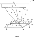
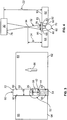
- the bridge piece 60 is, for example, but not limited to, any wire 70 (see FIG. 4 ), shim 72 (see FIG. 3 ) or other filler material that sufficiently fits into the gap 50 and is generally adjacent to or touching the components 62 and 64 to be welded.
- the bridge piece 60 is, for example, but not limited to, a stacked wire, a stacked shim, or combination thereof.
- the height of the shim 72 is less than the height of the components 62 and 64. In another embodiment, the shim height is equal to or greater than that of the components 62 and 64.
- the combined energy from the defocused laser 30 and electric arc welder 40 are directed toward the components 62 and 64 and the gap 50 to create a common molten pool 52.
- the common molten pool 52 operates to provide a full penetration weld 54 to bridge the gap 50 between components 62 and 64 at a high constant weld speed.
- common molten pool 52 refers to the molten material 53 created by the weld arc 42 of the electric arc welder 40 that includes a portion of the component edges 63 and 65 and the consumable wire electrode 44 (if present), this molten material 53 is further energized by the defocused hybrid laser 30 thereby causing the molten material 53 to penetrate deeper to include the bridge piece 60 to form the common molten pool 52.
- the metal from the bridge piece 60 becomes molten and intermixed with the other molten materials 53 to form a common molten pool 52.
- the intermixed molten materials from the common molten pool 52 join upon cooling to form one continuous piece or a weld 54 (see FIG. 5 ) joining the components 62 and 64.
- the defocused laser 30 and the electric arc welder are automated.
- the defocused laser 30 and electric arc welder 40 are mounted in separate places or mounted on a single mount 90, see FIG. 1 .
- the mount 90 is moved at a suitable rate of speed for welding, between approximately 762 millimeters per minute (30 inches per minute) to approximately 3048 millimeters per minute (120 inches per minute), or alternatively between approximately 1016 millimeters per minute (40 inches per minute) to approximately 2286 millimeters (90 inches per minute), or alternatively between approximately 1270 millimeters per minute (50 inches per minute) to approximately 2032 millimeters (80 inches per minute) to achieve a full penetration weld 54 between the components 62 and 64.
- the defocused laser 30 leads the electric arc welder 40 in the weld direction 66.
- the distance 38 between the defocused laser beam 32 and consumable wire electrode 44 of electric arc welder 40 is between approximately 2.5 millimeters to approximately 12 millimeters, or alternatively between approximately 3.0 millimeters to approximately 8.0 millimeters, or alternatively between approximately 3.5 millimeters to approximately 6.0 millimeters to obtain adequate interaction of the two heat sources to create a stable common molten pool 52.
- Distances 38 under 2.5 millimeters cause the defocused laser beam 32 to contact the electrode 44 of the electric arc welder 40 which results in molten material splattering and an unstable weld arc 42.
- Distances 38 greater than 12 millimeters do not allow for adequate interaction of the defocused laser beam 32 and weld arc 44 to create the desired common molten pool 52.
- the defocused laser 30 is behind the electric arc welder 40 in the weld direction 66.
- the distance 38 between the defocused laser beam 32 and consumable wire electrode 44 of electric arc welder 40 is between approximately 2.5 millimeters to approximately 12 millimeters, to obtain adequate interaction of the two heat sources to create a stable common molten pool 52.
- the electric arc welder 40 is selected from welders including consumable electrodes, such as, but not limited to, a gas metal arc welder (GMAW), a flux cored arc welder (FCAW) and welders having non-consumable electrodes with wire feeding, such as, but not limited to, a gas tungsten arc welder (GTAW) with wire feeding and a plasma arc welder (PAW) with wire feeding.
- GMAW gas metal arc welder
- FCAW flux cored arc welder
- GTAW gas tungsten arc welder
- PAW plasma arc welder
- the defocused laser 30 provides additional energy to the molten material 53 to allow for further penetration and to melt the bridge piece 60 to form the common molten pool 52.
- the electric arc welder 40 may also emit shielding gas for protecting the weld during welding.
- the defocused laser 30 is selected from a Nd: YAG laser, a CO 2 laser, a fiber laser, and a disk laser.
- the defocused laser 30 is a high-density powered laser.
- the defocused laser 30 has a defocused laser beam 32.
- the defocused high-density laser 30 has a positively defocused laser beam 32.
- a "positively defocused" beam it is meant that the focus point 34 of the laser 30 is above the surface 83 and 85 of the components 62 and 64 to be joined, such that the remaining energy or defocused beam 32 from the defocused laser 30 is directed outward towards the surface 83 and 85 of components 62 and 64 or the common molten pool 52 in a wider manner.
- the positively defocused beam 32 unlike a focused laser beam, provides energy that is more evenly dispersed over a distance "C" 26, instead of at a single point on the surface of one or more of the components 62 and 64. Focused lasers, because of the energy density directed to one point, result in keyholes in the material, thereby causing the molten material to blow through the bottom of the weld. In the present embodiment, the defocused laser beam 32 effectively increases the area heated or energized and allows for a deeper penetration weld in the material. The defocused laser beam 32 adds energy and/or heat to the molten material 53 created by the electric arc welder 40 to allow for further penetration of the weld and melting of the bridge piece 60 to create the common molten pool 52. The common molten pool 52 provides a full penetration weld 54 (see FIG. 5 ) between the components 62 and 64.
- the distance “A” 22 is the distance from the laser head 78 to the top surface 83 and 85 of the components 62 and 64.
- Distance “A” 22 is typically defined by the manufacture of the laser head. In one embodiment, distance “A” 22 between the laser head 78 and the top surface 83 and 85 of the components 62 and 64 remains fixed. In an alternative embodiment, distance “A” 22 between the laser head 78 and top surface 83 and 85 of the components 62 and 64 is varied.
- the defocus distance “B” 24 is the distance from the laser focus point 34 to the top surface 83 and 85 of the components 62 and 64. The defocus distance “B” 24 is varied depending on the size of the gap 50 to be welded.
- the defocus distance "B" 24 is approximately 5 millimeters to approximately 15 millimeters, or alternatively approximately 8 millimeters to approximately 13 millimeters, or alternatively approximately 10 millimeters to approximately 12 millimeters.
- the common molten pool 52 created by hybrid welder 20 includes molten material 53 and the melted bridge piece 60.
- the molten material 53 is generally a deposit from a consumable electrode or wire 44 melted by the arc 42 of the electric welder 40 and a portion of the melted surface 63 and 65 of the components 62 and 64.
- the additional energy provided from the defocused laser 30 by way of the defocused laser beam 32 allows for a deeper and wider penetration weld by effectively bringing down the molten material 53, such that molten material 53 contacts and melts the bridge piece 60 to form the common molten pool 52.
- the defocused laser beam 32 provides the additional energy to allow the molten material 53 to melt the bridge piece 60 and form the common molten pool 52 but prevents blowouts or dropping of the weld through the bridge piece 60 to provide a full penetration weld 74 as shown in FIG. 5 .
- the hybrid welding system 10 welds joints 80 using a bridge piece 60 having gaps 50 between components 62 and 64.
- Joints that can be welded using the hybrid welding system 10 include, but are not limited to, butt weld joints, edge weld joints, tee weld joints, and corner weld joints.
- the components 62 and 64 to be welded are selected from materials such as ferrous and non-ferrous materials.
- ferrous and non-ferrous materials are, but not limited to, superalloys, mild steel, high-strength steel, stainless steel, titanium, aluminum, and combinations thereof.
- the bridge piece 60 is selected from a shim, stacked shims, wire, stacked wires, or a combination thereof. In one embodiment, the bridge piece 60 is selected from materials that are similar to the component 62 and 64 materials. In another embodiment, the bridge piece is selected from a material that is different from the components 62 and 64.
- a method of welding at least two adjacent components 62 and 64 having a gap 50 of up to approximately 3.0 millimeters using the hybrid welding system 10 is provided.
- the hybrid welder 20, having an defocused laser 30 and an electric arc welder 40, is positioned above at least two components 62 and 64 to be welded or at least two components to be welded 62 and 64 are positioned below the hybrid welder 20.
- the at least two components 62 and 64 are aligned such that a gap 50 of up to approximately 3.0 millimeters is present between the at least two components 62 and 64.
- a bridge piece 60 is placed adjacent to one or both of the aligned components 62 and 64.
- the width of the bridge piece 60 is selected such that the bridge piece 60 generally has the same width as the gap 50.
- more than one pass with the hybrid welder 20 can be used to provide a full penetration weld 54.
- the method of welding is performed with a backing plate at a high constant weld speed to obtain a full penetration weld 54 with desired quality.
- One advantage of an embodiment of the present disclosure includes a method and apparatus that permits high constant welding speeds.
- Another advantage of an embodiment of the present disclosure is faster welding speeds for thinner materials.
- Yet another advantage of an embodiment of the present disclosure is high constant weld speeds for uneven gaps and mismatches in the components to be welded.
- Another advantage of an embodiment of the present disclosure is that a full penetration weld is achieved for gaps of up to approximately 3 millimeters in size.
- Another advantage of an embodiment of the present disclosure is that a full penetration weld is achieved for uneven gaps of up to approximately 3 millimeters in size.
- Two 3 millimeter thick stainless steel plates were welded using a hybrid welding system 10 including a defocused high-density laser 30 and an electric arc welder 40.
- the gap 50 that was bridged between the 3 millimeter thick stainless steel plates was measured and was approximately 2.34 millimeters.
- the defocused high-density laser 30 led the electric arc welder 40 to create a common molten pool 52, which resulted in a full penetration weld 52 between the two stainless steel plates.
- the laser used was a lamp-pumped ND:YAG laser having a laser power of 3kW.
- the electric arc welder 40 was a GMAW set at 26 Volts and a wire feeding speed of 450 inches per minute.
- FIG. 6 is a cross-section of the full penetration weld 54 obtained using hybrid welding system 10 of the present disclosure.
- the weld 54 includes a top bead 74 and under bead 76.
Landscapes
- Engineering & Computer Science (AREA)
- Physics & Mathematics (AREA)
- Optics & Photonics (AREA)
- Mechanical Engineering (AREA)
- Plasma & Fusion (AREA)
- Laser Beam Processing (AREA)
- Arc Welding In General (AREA)
Claims (11)
- Procédé consistant à souder au moins deux composants adjacents (62, 64) ayant des surfaces supérieures (83, 85), le procédé comprenant les étapes suivantes :se procurer les deux composants adjacents (62, 64) ayant entre eux un espace (50) allant jusqu'à environ 3,0 millimètres ;se procurer un dispositif de soudage hybride (20) ayant un laser (30) avec un faisceau laser (32) et un point de focalisation (34) et un dispositif de soudage à l'arc électrique (40), caractérisé en ce quele dispositif de soudage électrique a une électrode nue consommable (44), le point de focalisation (34) du laser (30) étant positionné au-dessus des surfaces supérieures (83, 85) des au moins deux composants adjacents (62, 64) ;caractérisé en outre par les étapes suivantes :placer une pièce de liaison (60) adjacente à l'un des composants adjacents (62, 64) ou les deux ;ajuster la distance du point de focalisation (34) du laser (30) depuis les surfaces supérieures (83, 85) des composants adjacents (62, 64) en fonction de la taille de l'espace (50) entre eux ; etdiriger de l'énergie vers un des composants adjacents (62, 64) ou les deux à une vitesse de soudage constante élevée entre environ 760 millimètres par minute et environ 3050 millimètres par minute de manière à créer un bain de fusion commun (52), le laser (30) fournissant de l'énergie supplémentaire permettant au bain de fusion commun de faire fondre l'au moins une pièce de liaison, le dispositif de soudage hybride (20) et le laser fournissant une soudure à pleine pénétration (54) assemblant les composants (62, 64) au refroidissement, et la distance entre le faisceau laser (32) et l'électrode nue consommable (44) du dispositif de soudage à l'arc électrique (40) se situant entre environ 2,5 mm et 12 mm dans la direction de la soudure.
- Procédé de la revendication 1, dans lequel le laser défocalisé (30) est choisi parmi un laser Nd:YAG, un laser au CO2, un laser à fibre, et un laser à disque.
- Procédé de la revendication 1 ou 2, dans lequel le dispositif de soudage à l'arc électrique (40) est choisi parmi un dispositif de soudage à l'arc en atmosphère inerte avec électrode de tungstène, un dispositif de soudage à l'arc en atmosphère inerte avec électrode fusible, un dispositif de soudage à l'arc au fil fourré, et un dispositif de soudage à l'arc plasma.
- Procédé de l'une quelconque des revendications 1 à 3, dans lequel une pluralité de lasers (30) ayant chacun son point de focalisation respectif positionné au-dessus des surfaces supérieures des au moins deux composants adjacents, et une pluralité de dispositifs de soudage à l'arc électrique (40) sont utilisés pour combler l'espace (50).
- Procédé de l'une quelconque de la revendication 1 à 4, le procédé étant effectué en une seule passe ou en plusieurs passes.
- Procédé de l'une quelconque des revendications 1 à 5, le procédé étant effectué sans plaque d'appui.
- Procédé d'une quelconque revendication précédente, dans lequel la pièce de liaison (60) est dimensionnée pour remplir l'espace (50).
- Procédé d'une quelconque revendication précédente, dans lequel l'au moins une pièce de liaison (60) est une cale (72), une cale empilée, un fil (70), un fil empilé, et la pièce de liaison (60) est dimensionnée pour remplir l'espace (50).
- Système de soudage hybride comprenant :un dispositif de soudage hybride (20), le dispositif de soudage hybride ayant un laser (30) avec un faisceau laser (32) et un point de focalisation (34) et un dispositif de soudage à l'arc électrique (40),au moins deux composants adjacents (62, 64) à souder, les au moins deux composants adjacents (62, 64) ayant des surfaces supérieures (83, 85) ;caractérisé en ce que le dispositif de soudage à l'arc électrique a une électrode nue consommable (44) et en ce que le système comprend en outre au moins une pièce de liaison (60),dans lequel à l'usage les au moins deux composants adjacents (62, 64) à souder sont agencés avec un espace (50) entre eux allant jusqu'à environ 3,0 millimètres et l'au moins une pièce de liaison (60) est adjacente à un ou plusieurs des au moins deux composants (62, 64),le point de focalisation (34) du laser (30) est adapté pour être ajusté à une distance prédéterminée (B) au-dessus des surfaces supérieures (83, 85) des au moins deux composants adjacents (62, 64) en fonction de la taille de l'espace (50) entre eux, etle laser (30) et le dispositif de soudage à l'arc électrique (40) sont agencés et disposés pour diriger de l'énergie vers les au moins deux composants adjacents (62, 64) à une vitesse de soudage constante élevée entre environ 760 millimètres par minute et environ 3050 millimètres par minute, de manière à créer un bain de fusion commun (52), utilisable pour fournir une soudure à pleine pénétration pour combler l'espace (50), la distance entre le faisceau laser (32) et l'électrode nue consommable (44) du dispositif de soudage à l'arc électrique (40) se situant entre environ 2,5 mm et 12 mm dans la direction de la soudure.
- Système de soudage hybride de la revendication 9, dans lequel le laser (30) est choisi parmi un laser Nd:YAG, un laser au CO2, un laser à fibre, et un laser à disque.
- Système de soudage hybride de la revendication 9 ou 10, dans lequel le dispositif de soudage à l'arc électrique (40) est choisi parmi un dispositif de soudage à l'arc en atmosphère inerte avec électrode de tungstène avec avance de fil, un dispositif de soudage à l'arc en atmosphère inerte avec électrode fusible, un dispositif de soudage à l'arc au fil fourré, et un dispositif de soudage à l'arc plasma avec avance de fil.
Applications Claiming Priority (1)
| Application Number | Priority Date | Filing Date | Title |
|---|---|---|---|
| US13/086,114 US8546720B2 (en) | 2011-04-13 | 2011-04-13 | Hybrid welding apparatus and system and method of welding |
Publications (2)
| Publication Number | Publication Date |
|---|---|
| EP2511041A1 EP2511041A1 (fr) | 2012-10-17 |
| EP2511041B1 true EP2511041B1 (fr) | 2018-06-13 |
Family
ID=45977234
Family Applications (1)
| Application Number | Title | Priority Date | Filing Date |
|---|---|---|---|
| EP12163444.8A Active EP2511041B1 (fr) | 2011-04-13 | 2012-04-05 | Système de soudage hybride et procédé de soudage |
Country Status (4)
| Country | Link |
|---|---|
| US (1) | US8546720B2 (fr) |
| EP (1) | EP2511041B1 (fr) |
| CN (1) | CN102728960B (fr) |
| IN (1) | IN2012DE00929A (fr) |
Families Citing this family (22)
| Publication number | Priority date | Publication date | Assignee | Title |
|---|---|---|---|---|
| JP5646646B2 (ja) * | 2009-12-16 | 2014-12-24 | イーエスエービー・エービー | 溶接方法および溶接装置 |
| EP2543443B1 (fr) * | 2010-03-04 | 2019-01-09 | Imagineering, Inc. | Dispositif de formation de revêtement et procédé de production d'une matière de formation de revêtement |
| CA2830594C (fr) * | 2011-04-15 | 2018-10-30 | Magna International Inc. | Ensemble et procede de soudage au laser |
| US8766140B2 (en) | 2011-10-06 | 2014-07-01 | Lincoln Global, Inc. | Apparatus and method for laser cleaning of coated materials prior to welding |
| US20130087543A1 (en) * | 2011-10-06 | 2013-04-11 | Lincoln Global, Inc. | Apparatus and method for post weld laser release of gas build up in a gmaw weld |
| US20130309000A1 (en) * | 2012-05-21 | 2013-11-21 | General Electric Comapny | Hybrid laser arc welding process and apparatus |
| US20140065320A1 (en) * | 2012-08-30 | 2014-03-06 | Dechao Lin | Hybrid coating systems and methods |
| WO2014094882A1 (fr) * | 2012-12-21 | 2014-06-26 | European Space Agency | Procédé d'impression 3d utilisant une source de chauffage de lumière focalisée |
| US10981248B2 (en) | 2013-11-22 | 2021-04-20 | General Electric Company | Hybrid welding apparatuses, systems and methods for spatially offset components |
| WO2015162445A1 (fr) | 2014-04-25 | 2015-10-29 | Arcelormittal Investigación Y Desarrollo Sl | Procede et dispositif de preparation de toles d'acier aluminiees destinees a etre soudees puis durcies sous presse; flan soude correspondant |
| ES2627220T3 (es) * | 2014-05-09 | 2017-07-27 | Gestamp Hardtech Ab | Métodos para la unión de dos formatos y los formatos y los productos obtenidos |
| DE112015003499T5 (de) * | 2014-07-28 | 2017-06-14 | Siemens Energy, Inc. | Lasermetallbearbeitung reflektierender Metalle unter Verwendung eines Flussmittels |
| US10118249B2 (en) | 2015-10-15 | 2018-11-06 | GM Global Technology Operations LLC | Laser beam welding with a spiral weld path having a first order of continuity |
| WO2017102004A1 (fr) * | 2015-12-17 | 2017-06-22 | Strukton Rail B.V. | Procédé de soudage de rails |
| CN106112267B (zh) * | 2016-08-25 | 2017-10-13 | 湖南汽车工程职业学院 | 一种az系镁合金焊接材料及其焊接控制方法 |
| CN106735909A (zh) * | 2017-02-07 | 2017-05-31 | 王长春 | 一种用于激光束和等离子弧复合焊接的焊炬 |
| JP7119960B2 (ja) * | 2018-12-03 | 2022-08-17 | 日本軽金属株式会社 | 接合方法 |
| US11583954B2 (en) * | 2019-03-04 | 2023-02-21 | Kabushiki Kaisha Toshiba | Welding method |
| JP7284014B2 (ja) * | 2019-07-10 | 2023-05-30 | 株式会社ダイヘン | レーザ・アークハイブリッド溶接装置 |
| US20210031297A1 (en) * | 2019-08-01 | 2021-02-04 | GM Global Technology Operations LLC | System and method for multi-task laser welding |
| CN110722264A (zh) * | 2019-11-19 | 2020-01-24 | 中国科学院合肥物质科学研究院 | 一种间隙适应性强的大功率激光焊接方法 |
| CA3165854A1 (fr) * | 2019-12-25 | 2021-07-01 | Nippon Light Metal Company, Ltd. | Procede d'assemblage |
Citations (1)
| Publication number | Priority date | Publication date | Assignee | Title |
|---|---|---|---|---|
| US20080011720A1 (en) * | 2006-07-12 | 2008-01-17 | L'air Liquide Societe Anonyme Pour L'etude Et L'exploitation Des Procedes Georges Claude | Process for laser-ARC hybrid welding aluminized metal workpieces |
Family Cites Families (22)
| Publication number | Priority date | Publication date | Assignee | Title |
|---|---|---|---|---|
| JPS60216989A (ja) | 1984-04-10 | 1985-10-30 | Mitsubishi Electric Corp | レ−ザビ−ム加工装置 |
| US5006688A (en) | 1988-10-24 | 1991-04-09 | Westinghouse Electric Corp. | Laser-arc apparatus and method for controlling plasma cloud |
| US5700989A (en) | 1994-12-30 | 1997-12-23 | Dykhno; Igor S. | Combined laser and plasma arc welding torch |
| US5603853A (en) * | 1995-02-28 | 1997-02-18 | The Twentyfirst Century Corporation | Method of high energy density radiation beam lap welding |
| DE19916831A1 (de) | 1999-04-14 | 2000-10-19 | Peter Krull | Verfahren zum Laser-WIG-Schweißen beschichteter Stahlbleche |
| FR2829414B1 (fr) | 2001-09-13 | 2003-10-31 | Air Liquide | Procede de soudage hybride laser-arc avec ajustage des debits de gaz |
| US7154065B2 (en) * | 2002-05-24 | 2006-12-26 | Alcon Inc. | Laser-hybrid welding with beam oscillation |
| US6906281B2 (en) * | 2003-03-03 | 2005-06-14 | Dana Corporation | Method for laser welding of metal |
| JP2005040806A (ja) * | 2003-07-24 | 2005-02-17 | Daihen Corp | 亜鉛メッキ鋼板のレーザ照射アーク溶接方法 |
| US20070017906A1 (en) | 2005-06-30 | 2007-01-25 | General Electric Company | Shimmed laser beam welding process for joining superalloys for gas turbine applications |
| US8242410B2 (en) * | 2006-07-14 | 2012-08-14 | Lincoln Global, Inc. | Welding methods and systems |
| EP1880791A1 (fr) | 2006-07-21 | 2008-01-23 | Aleris Aluminum Koblenz GmbH | Procédé et appareil pour l'assemblage par laser de deux composants utilisant un flux laminiare de gaz inert coaxial avec un fil d'apport métallique |
| CN1943959A (zh) * | 2006-10-20 | 2007-04-11 | 大连理工大学 | 一种激光-电弧复合加工方法 |
| JP2010031659A (ja) | 2008-07-25 | 2010-02-12 | Nippon Densan Corp | 直列式軸流ファン |
| US20100078412A1 (en) | 2008-09-30 | 2010-04-01 | Caterpillar Inc. | Hybrid welding method |
| US7874471B2 (en) * | 2008-12-23 | 2011-01-25 | Exxonmobil Research And Engineering Company | Butt weld and method of making using fusion and friction stir welding |
| CN101811231B (zh) * | 2009-02-20 | 2011-08-17 | 机械科学研究院哈尔滨焊接研究所 | 一种激光-冷金属过渡电弧复合热源焊接方法 |
| US8319148B2 (en) * | 2009-08-20 | 2012-11-27 | General Electric Company | System and method of dual laser beam welding of first and second filler metals |
| CN101670495B (zh) * | 2009-09-28 | 2011-11-09 | 北京工业大学 | 中厚航天高强铝合金板的激光-tig电弧复合焊接工艺 |
| KR101116638B1 (ko) * | 2009-12-15 | 2012-03-07 | 주식회사 성우하이텍 | 강판의 레이저 용접방법 |
| US8729424B2 (en) | 2010-02-18 | 2014-05-20 | The Esab Group, Inc. | Hybrid welding with multiple heat sources |
| US8253061B2 (en) * | 2010-07-07 | 2012-08-28 | General Electric Company | Hybrid laser arc welding process and apparatus |
-
2011
- 2011-04-13 US US13/086,114 patent/US8546720B2/en active Active
-
2012
- 2012-03-28 IN IN929DE2012 patent/IN2012DE00929A/en unknown
- 2012-04-05 EP EP12163444.8A patent/EP2511041B1/fr active Active
- 2012-04-12 CN CN201210114953.1A patent/CN102728960B/zh active Active
Patent Citations (1)
| Publication number | Priority date | Publication date | Assignee | Title |
|---|---|---|---|---|
| US20080011720A1 (en) * | 2006-07-12 | 2008-01-17 | L'air Liquide Societe Anonyme Pour L'etude Et L'exploitation Des Procedes Georges Claude | Process for laser-ARC hybrid welding aluminized metal workpieces |
Also Published As
| Publication number | Publication date |
|---|---|
| US20120261389A1 (en) | 2012-10-18 |
| CN102728960B (zh) | 2017-07-14 |
| US8546720B2 (en) | 2013-10-01 |
| IN2012DE00929A (fr) | 2015-09-04 |
| CN102728960A (zh) | 2012-10-17 |
| EP2511041A1 (fr) | 2012-10-17 |
Similar Documents
| Publication | Publication Date | Title |
|---|---|---|
| EP2511041B1 (fr) | Système de soudage hybride et procédé de soudage | |
| US8890030B2 (en) | Hybrid welding apparatuses, systems and methods | |
| US8610031B2 (en) | Method of arc welding root pass | |
| US9221118B2 (en) | Adaptive control hybrid welding system and methods of controlling | |
| EP2698223B1 (fr) | Procédé de soudage pour la réparation de sections épaisses utilisant deux dispositifs de soudage à l'arc et un dispositif de soudage laser | |
| US9718147B2 (en) | Method and system to start and use combination filler wire feed and high intensity energy source for root pass welding of the inner diameter of clad pipe | |
| US20140027414A1 (en) | Hybrid welding system and method of welding | |
| CN102126084B (zh) | 钢板的激光焊接方法 | |
| EP2666579B1 (fr) | Procédé de soudure à l'arc laser hybride et appareil | |
| JP5905074B2 (ja) | ハイブリッド・レーザ・サブマージアーク溶接プロセスを用いた厚板接合方法及び装置 | |
| EP2596896B1 (fr) | Système et procédé de soudage avec un dispositif laser, un dispositif MIG/MAG et un dispositif TIG | |
| WO2014140763A2 (fr) | Système et procédé de soudage d'acier inoxydable à un placage de cuivre | |
| WO2014087227A1 (fr) | Procédé et système pour démarrer et utiliser une alimentation en fil d'apport et une source d'énergie de forte intensité combinées en vue d'un soudage | |
| JP5153368B2 (ja) | T型継手の貫通溶接方法及び貫通溶接構造物 | |
| JP5318543B2 (ja) | レーザ・アーク複合溶接法 | |
| CN109641306B (zh) | 立式窄坡口气体保护弧焊方法 | |
| JP5416422B2 (ja) | レーザ・アーク複合溶接法 | |
| US20080206586A1 (en) | Penetration welding method of t-type joint and penetration welding structure of t-type joint | |
| US5945014A (en) | Method of arc welding heavy steel plates | |
| JP2014079783A (ja) | レーザ・アークハイブリッド溶接方法、ハイブリッド溶接用ヘッド、及びハイブリッド溶接装置 | |
| JP2010167425A (ja) | 上下t型継手の溶接方法及び上下t型溶接継手並びにこれを用いた溶接構造物 | |
| US10981248B2 (en) | Hybrid welding apparatuses, systems and methods for spatially offset components | |
| US7371994B2 (en) | Buried arc welding of integrally backed square butt joints | |
| JP5483553B2 (ja) | レーザ・アーク複合溶接法 |
Legal Events
| Date | Code | Title | Description |
|---|---|---|---|
| PUAI | Public reference made under article 153(3) epc to a published international application that has entered the european phase |
Free format text: ORIGINAL CODE: 0009012 |
|
| AK | Designated contracting states |
Kind code of ref document: A1 Designated state(s): AL AT BE BG CH CY CZ DE DK EE ES FI FR GB GR HR HU IE IS IT LI LT LU LV MC MK MT NL NO PL PT RO RS SE SI SK SM TR |
|
| AX | Request for extension of the european patent |
Extension state: BA ME |
|
| 17P | Request for examination filed |
Effective date: 20130417 |
|
| 17Q | First examination report despatched |
Effective date: 20141009 |
|
| STAA | Information on the status of an ep patent application or granted ep patent |
Free format text: STATUS: EXAMINATION IS IN PROGRESS |
|
| GRAP | Despatch of communication of intention to grant a patent |
Free format text: ORIGINAL CODE: EPIDOSNIGR1 |
|
| STAA | Information on the status of an ep patent application or granted ep patent |
Free format text: STATUS: GRANT OF PATENT IS INTENDED |
|
| INTG | Intention to grant announced |
Effective date: 20171130 |
|
| GRAS | Grant fee paid |
Free format text: ORIGINAL CODE: EPIDOSNIGR3 |
|
| GRAA | (expected) grant |
Free format text: ORIGINAL CODE: 0009210 |
|
| STAA | Information on the status of an ep patent application or granted ep patent |
Free format text: STATUS: THE PATENT HAS BEEN GRANTED |
|
| AK | Designated contracting states |
Kind code of ref document: B1 Designated state(s): AL AT BE BG CH CY CZ DE DK EE ES FI FR GB GR HR HU IE IS IT LI LT LU LV MC MK MT NL NO PL PT RO RS SE SI SK SM TR |
|
| REG | Reference to a national code |
Ref country code: GB Ref legal event code: FG4D |
|
| REG | Reference to a national code |
Ref country code: CH Ref legal event code: EP Ref country code: AT Ref legal event code: REF Ref document number: 1007969 Country of ref document: AT Kind code of ref document: T Effective date: 20180615 |
|
| REG | Reference to a national code |
Ref country code: IE Ref legal event code: FG4D |
|
| REG | Reference to a national code |
Ref country code: DE Ref legal event code: R096 Ref document number: 602012047353 Country of ref document: DE |
|
| REG | Reference to a national code |
Ref country code: NL Ref legal event code: MP Effective date: 20180613 |
|
| REG | Reference to a national code |
Ref country code: LT Ref legal event code: MG4D |
|
| PG25 | Lapsed in a contracting state [announced via postgrant information from national office to epo] |
Ref country code: FI Free format text: LAPSE BECAUSE OF FAILURE TO SUBMIT A TRANSLATION OF THE DESCRIPTION OR TO PAY THE FEE WITHIN THE PRESCRIBED TIME-LIMIT Effective date: 20180613 Ref country code: BG Free format text: LAPSE BECAUSE OF FAILURE TO SUBMIT A TRANSLATION OF THE DESCRIPTION OR TO PAY THE FEE WITHIN THE PRESCRIBED TIME-LIMIT Effective date: 20180913 Ref country code: LT Free format text: LAPSE BECAUSE OF FAILURE TO SUBMIT A TRANSLATION OF THE DESCRIPTION OR TO PAY THE FEE WITHIN THE PRESCRIBED TIME-LIMIT Effective date: 20180613 Ref country code: CY Free format text: LAPSE BECAUSE OF FAILURE TO SUBMIT A TRANSLATION OF THE DESCRIPTION OR TO PAY THE FEE WITHIN THE PRESCRIBED TIME-LIMIT Effective date: 20180613 Ref country code: NO Free format text: LAPSE BECAUSE OF FAILURE TO SUBMIT A TRANSLATION OF THE DESCRIPTION OR TO PAY THE FEE WITHIN THE PRESCRIBED TIME-LIMIT Effective date: 20180913 Ref country code: SE Free format text: LAPSE BECAUSE OF FAILURE TO SUBMIT A TRANSLATION OF THE DESCRIPTION OR TO PAY THE FEE WITHIN THE PRESCRIBED TIME-LIMIT Effective date: 20180613 Ref country code: ES Free format text: LAPSE BECAUSE OF FAILURE TO SUBMIT A TRANSLATION OF THE DESCRIPTION OR TO PAY THE FEE WITHIN THE PRESCRIBED TIME-LIMIT Effective date: 20180613 |
|
| PG25 | Lapsed in a contracting state [announced via postgrant information from national office to epo] |
Ref country code: GR Free format text: LAPSE BECAUSE OF FAILURE TO SUBMIT A TRANSLATION OF THE DESCRIPTION OR TO PAY THE FEE WITHIN THE PRESCRIBED TIME-LIMIT Effective date: 20180914 Ref country code: LV Free format text: LAPSE BECAUSE OF FAILURE TO SUBMIT A TRANSLATION OF THE DESCRIPTION OR TO PAY THE FEE WITHIN THE PRESCRIBED TIME-LIMIT Effective date: 20180613 Ref country code: HR Free format text: LAPSE BECAUSE OF FAILURE TO SUBMIT A TRANSLATION OF THE DESCRIPTION OR TO PAY THE FEE WITHIN THE PRESCRIBED TIME-LIMIT Effective date: 20180613 Ref country code: RS Free format text: LAPSE BECAUSE OF FAILURE TO SUBMIT A TRANSLATION OF THE DESCRIPTION OR TO PAY THE FEE WITHIN THE PRESCRIBED TIME-LIMIT Effective date: 20180613 |
|
| REG | Reference to a national code |
Ref country code: AT Ref legal event code: MK05 Ref document number: 1007969 Country of ref document: AT Kind code of ref document: T Effective date: 20180613 |
|
| PG25 | Lapsed in a contracting state [announced via postgrant information from national office to epo] |
Ref country code: NL Free format text: LAPSE BECAUSE OF FAILURE TO SUBMIT A TRANSLATION OF THE DESCRIPTION OR TO PAY THE FEE WITHIN THE PRESCRIBED TIME-LIMIT Effective date: 20180613 |
|
| PG25 | Lapsed in a contracting state [announced via postgrant information from national office to epo] |
Ref country code: RO Free format text: LAPSE BECAUSE OF FAILURE TO SUBMIT A TRANSLATION OF THE DESCRIPTION OR TO PAY THE FEE WITHIN THE PRESCRIBED TIME-LIMIT Effective date: 20180613 Ref country code: SK Free format text: LAPSE BECAUSE OF FAILURE TO SUBMIT A TRANSLATION OF THE DESCRIPTION OR TO PAY THE FEE WITHIN THE PRESCRIBED TIME-LIMIT Effective date: 20180613 Ref country code: CZ Free format text: LAPSE BECAUSE OF FAILURE TO SUBMIT A TRANSLATION OF THE DESCRIPTION OR TO PAY THE FEE WITHIN THE PRESCRIBED TIME-LIMIT Effective date: 20180613 Ref country code: PL Free format text: LAPSE BECAUSE OF FAILURE TO SUBMIT A TRANSLATION OF THE DESCRIPTION OR TO PAY THE FEE WITHIN THE PRESCRIBED TIME-LIMIT Effective date: 20180613 Ref country code: AT Free format text: LAPSE BECAUSE OF FAILURE TO SUBMIT A TRANSLATION OF THE DESCRIPTION OR TO PAY THE FEE WITHIN THE PRESCRIBED TIME-LIMIT Effective date: 20180613 Ref country code: EE Free format text: LAPSE BECAUSE OF FAILURE TO SUBMIT A TRANSLATION OF THE DESCRIPTION OR TO PAY THE FEE WITHIN THE PRESCRIBED TIME-LIMIT Effective date: 20180613 Ref country code: IS Free format text: LAPSE BECAUSE OF FAILURE TO SUBMIT A TRANSLATION OF THE DESCRIPTION OR TO PAY THE FEE WITHIN THE PRESCRIBED TIME-LIMIT Effective date: 20181013 |
|
| PG25 | Lapsed in a contracting state [announced via postgrant information from national office to epo] |
Ref country code: SM Free format text: LAPSE BECAUSE OF FAILURE TO SUBMIT A TRANSLATION OF THE DESCRIPTION OR TO PAY THE FEE WITHIN THE PRESCRIBED TIME-LIMIT Effective date: 20180613 |
|
| REG | Reference to a national code |
Ref country code: DE Ref legal event code: R097 Ref document number: 602012047353 Country of ref document: DE |
|
| PLBE | No opposition filed within time limit |
Free format text: ORIGINAL CODE: 0009261 |
|
| STAA | Information on the status of an ep patent application or granted ep patent |
Free format text: STATUS: NO OPPOSITION FILED WITHIN TIME LIMIT |
|
| 26N | No opposition filed |
Effective date: 20190314 |
|
| PG25 | Lapsed in a contracting state [announced via postgrant information from national office to epo] |
Ref country code: DK Free format text: LAPSE BECAUSE OF FAILURE TO SUBMIT A TRANSLATION OF THE DESCRIPTION OR TO PAY THE FEE WITHIN THE PRESCRIBED TIME-LIMIT Effective date: 20180613 Ref country code: SI Free format text: LAPSE BECAUSE OF FAILURE TO SUBMIT A TRANSLATION OF THE DESCRIPTION OR TO PAY THE FEE WITHIN THE PRESCRIBED TIME-LIMIT Effective date: 20180613 |
|
| PG25 | Lapsed in a contracting state [announced via postgrant information from national office to epo] |
Ref country code: AL Free format text: LAPSE BECAUSE OF FAILURE TO SUBMIT A TRANSLATION OF THE DESCRIPTION OR TO PAY THE FEE WITHIN THE PRESCRIBED TIME-LIMIT Effective date: 20180613 |
|
| REG | Reference to a national code |
Ref country code: BE Ref legal event code: MM Effective date: 20190430 |
|
| GBPC | Gb: european patent ceased through non-payment of renewal fee |
Effective date: 20190405 |
|
| PG25 | Lapsed in a contracting state [announced via postgrant information from national office to epo] |
Ref country code: MC Free format text: LAPSE BECAUSE OF FAILURE TO SUBMIT A TRANSLATION OF THE DESCRIPTION OR TO PAY THE FEE WITHIN THE PRESCRIBED TIME-LIMIT Effective date: 20180613 Ref country code: LU Free format text: LAPSE BECAUSE OF NON-PAYMENT OF DUE FEES Effective date: 20190405 |
|
| PG25 | Lapsed in a contracting state [announced via postgrant information from national office to epo] |
Ref country code: GB Free format text: LAPSE BECAUSE OF NON-PAYMENT OF DUE FEES Effective date: 20190405 |
|
| PG25 | Lapsed in a contracting state [announced via postgrant information from national office to epo] |
Ref country code: BE Free format text: LAPSE BECAUSE OF NON-PAYMENT OF DUE FEES Effective date: 20190430 |
|
| PG25 | Lapsed in a contracting state [announced via postgrant information from national office to epo] |
Ref country code: TR Free format text: LAPSE BECAUSE OF FAILURE TO SUBMIT A TRANSLATION OF THE DESCRIPTION OR TO PAY THE FEE WITHIN THE PRESCRIBED TIME-LIMIT Effective date: 20180613 |
|
| PG25 | Lapsed in a contracting state [announced via postgrant information from national office to epo] |
Ref country code: IE Free format text: LAPSE BECAUSE OF NON-PAYMENT OF DUE FEES Effective date: 20190405 |
|
| PG25 | Lapsed in a contracting state [announced via postgrant information from national office to epo] |
Ref country code: PT Free format text: LAPSE BECAUSE OF FAILURE TO SUBMIT A TRANSLATION OF THE DESCRIPTION OR TO PAY THE FEE WITHIN THE PRESCRIBED TIME-LIMIT Effective date: 20181015 |
|
| PG25 | Lapsed in a contracting state [announced via postgrant information from national office to epo] |
Ref country code: HU Free format text: LAPSE BECAUSE OF FAILURE TO SUBMIT A TRANSLATION OF THE DESCRIPTION OR TO PAY THE FEE WITHIN THE PRESCRIBED TIME-LIMIT; INVALID AB INITIO Effective date: 20120405 Ref country code: MT Free format text: LAPSE BECAUSE OF FAILURE TO SUBMIT A TRANSLATION OF THE DESCRIPTION OR TO PAY THE FEE WITHIN THE PRESCRIBED TIME-LIMIT Effective date: 20180613 |
|
| PG25 | Lapsed in a contracting state [announced via postgrant information from national office to epo] |
Ref country code: MK Free format text: LAPSE BECAUSE OF FAILURE TO SUBMIT A TRANSLATION OF THE DESCRIPTION OR TO PAY THE FEE WITHIN THE PRESCRIBED TIME-LIMIT Effective date: 20180613 |
|
| PGFP | Annual fee paid to national office [announced via postgrant information from national office to epo] |
Ref country code: FR Payment date: 20230321 Year of fee payment: 12 |
|
| PGFP | Annual fee paid to national office [announced via postgrant information from national office to epo] |
Ref country code: IT Payment date: 20230322 Year of fee payment: 12 |
|
| PGFP | Annual fee paid to national office [announced via postgrant information from national office to epo] |
Ref country code: DE Payment date: 20230321 Year of fee payment: 12 Ref country code: CH Payment date: 20230502 Year of fee payment: 12 |
|
| REG | Reference to a national code |
Ref country code: DE Ref legal event code: R081 Ref document number: 602012047353 Country of ref document: DE Owner name: GENERAL ELECTRIC TECHNOLOGY GMBH, CH Free format text: FORMER OWNER: GENERAL ELECTRIC COMPANY, SCHENECTADY, NY, US |