EP2508434B1 - Module de conditionnement, machine et procédé pour réaliser au moins deux opérations sur des récipients souples - Google Patents
Module de conditionnement, machine et procédé pour réaliser au moins deux opérations sur des récipients souples Download PDFInfo
- Publication number
- EP2508434B1 EP2508434B1 EP11382096.3A EP11382096A EP2508434B1 EP 2508434 B1 EP2508434 B1 EP 2508434B1 EP 11382096 A EP11382096 A EP 11382096A EP 2508434 B1 EP2508434 B1 EP 2508434B1
- Authority
- EP
- European Patent Office
- Prior art keywords
- chain
- operational
- wheel
- wheels
- container
- Prior art date
- Legal status (The legal status is an assumption and is not a legal conclusion. Google has not performed a legal analysis and makes no representation as to the accuracy of the status listed.)
- Not-in-force
Links
Images


Classifications
-
- B—PERFORMING OPERATIONS; TRANSPORTING
- B65—CONVEYING; PACKING; STORING; HANDLING THIN OR FILAMENTARY MATERIAL
- B65B—MACHINES, APPARATUS OR DEVICES FOR, OR METHODS OF, PACKAGING ARTICLES OR MATERIALS; UNPACKING
- B65B65/00—Details peculiar to packaging machines and not otherwise provided for; Arrangements of such details
- B65B65/003—Packaging lines, e.g. general layout
-
- B—PERFORMING OPERATIONS; TRANSPORTING
- B65—CONVEYING; PACKING; STORING; HANDLING THIN OR FILAMENTARY MATERIAL
- B65B—MACHINES, APPARATUS OR DEVICES FOR, OR METHODS OF, PACKAGING ARTICLES OR MATERIALS; UNPACKING
- B65B43/00—Forming, feeding, opening or setting-up containers or receptacles in association with packaging
- B65B43/42—Feeding or positioning bags, boxes, or cartons in the distended, opened, or set-up state; Feeding preformed rigid containers, e.g. tins, capsules, glass tubes, glasses, to the packaging position; Locating containers or receptacles at the filling position; Supporting containers or receptacles during the filling operation
- B65B43/46—Feeding or positioning bags, boxes, or cartons in the distended, opened, or set-up state; Feeding preformed rigid containers, e.g. tins, capsules, glass tubes, glasses, to the packaging position; Locating containers or receptacles at the filling position; Supporting containers or receptacles during the filling operation using grippers
- B65B43/465—Feeding or positioning bags, boxes, or cartons in the distended, opened, or set-up state; Feeding preformed rigid containers, e.g. tins, capsules, glass tubes, glasses, to the packaging position; Locating containers or receptacles at the filling position; Supporting containers or receptacles during the filling operation using grippers for bags
-
- B—PERFORMING OPERATIONS; TRANSPORTING
- B65—CONVEYING; PACKING; STORING; HANDLING THIN OR FILAMENTARY MATERIAL
- B65B—MACHINES, APPARATUS OR DEVICES FOR, OR METHODS OF, PACKAGING ARTICLES OR MATERIALS; UNPACKING
- B65B43/00—Forming, feeding, opening or setting-up containers or receptacles in association with packaging
- B65B43/42—Feeding or positioning bags, boxes, or cartons in the distended, opened, or set-up state; Feeding preformed rigid containers, e.g. tins, capsules, glass tubes, glasses, to the packaging position; Locating containers or receptacles at the filling position; Supporting containers or receptacles during the filling operation
- B65B43/52—Feeding or positioning bags, boxes, or cartons in the distended, opened, or set-up state; Feeding preformed rigid containers, e.g. tins, capsules, glass tubes, glasses, to the packaging position; Locating containers or receptacles at the filling position; Supporting containers or receptacles during the filling operation using roller-ways or endless conveyors
Definitions
- the present invention relates to a packaging module in which at least two operations are performed on flexible containers arranged in a row, said operations being those which are performed after the actual formation of the containers, such as the operations of opening, filling and closing the containers.
- the packaging module comprises at least two rotating operational wheels of vertical shafts, at least one of which is motor-operated. Said operational wheels are provided with corresponding means for carrying out the aforementioned operations on the containers.
- the module also comprises a drive chain or belt which links with the operational wheels, describing a closed trajectory.
- the invention also contemplates a horizontal packaging machine and a packaging method.
- automatic machines intended for the continuous packaging of liquid products, such as for example juices and soft drinks, granulated products, ground products or powdered products in flexible containers in the form of pouches.
- liquid products such as for example juices and soft drinks, granulated products, ground products or powdered products in flexible containers in the form of pouches.
- automatic packaging machines are provided with a formation line for forming pouches of a heat-sealing material and with a line for filling the pouches with the product to be packaged or packaging line which is linked with the former.
- Patent document ES2226518 discloses an automatic packaging machine comprising pouch formation means or means for supplying pre-made pouches, determining a virtual longitudinal axis, means for conveying pouches for their packaging and means for packaging pouches.
- the means for conveying pouches are linked with the pouch formation means or with the means for supplying pre-made pouches by means of a pouch transfer device.
- the means for conveying pouches comprise a pouch conveying guide which describes a closed trajectory made up of a first semi-circumferential portion and a second semi-circumferential portion mutually facing one another at the inner face thereof and linked at the corresponding ends by means of straight portions, forming an oblong interior in which means for packaging pouches are arranged, the conveying guide determining a virtual longitudinal axis.
- Horizontal packaging machines in turn are typically provided with a container formation module and a packaging module which cooperate such that the containers manufactured in the formation module are transferred individually or in batches to the packaging module, where operations such as opening, filling and closing said containers are carried out.
- the packaging modules known until now comprise a series of longitudinally aligned work stations where the aforementioned operations of opening, filling and closing are simultaneously carried out.
- the flexible containers are arranged in longitudinal alignment, separated from each other, according to the separating distance of the work stations, forming a packaging line which moves forward intermittently, thus displacing the containers from one station to the next.
- the machines are provided with a conveying carriage which simultaneously holds all the flexible containers of the packaging line and also simultaneously conveys them between two consecutive stations.
- patent document ES2257180 discloses a container conveying device that can be applied to automatic packaging machines, of the type provided with a formation line for forming flexible containers in the form of pouches from a sheet of heat-sealing material and with a packaging line in which the containers are at least filled and closed in corresponding stations in longitudinal alignment.
- the drawback of this type of arrangement is that the movement of the containers or groups of flexible containers is not continuous, but rather intermittent.
- the forward movement speed of the containers during the different packaging stations is very limited compared to the speed that could be attained because when the containers move forward intermittently, the liquid, granulated or powdered product contained therein may come out before the container is closed due to the ripple effect that would occur if the speed is not controlled.
- nonlinear machines for carrying out packaging operations on containers there are also nonlinear machines for carrying out packaging operations on containers, as the one disclosed in the document EP1023233-A1 .
- This kind of machines reminds the concept of the well-known packaging machines that work with rigid bottles that are subjected, for instance, to operations as fluid filling, gas insertion and cap application on its opening, each operation being carried out in respective devices in the form of a rotating wheels of vertical shafts, wherein the perimeter of the wheels has a number of receiving spaces for receiving a bottle in each one, transferring each bottle from the receiving space of a wheel to a receiving space of an adjacent wheel to carrying out the following packaging operation.
- the document EP1043233-A1 discloses a machine for filling and packaging flexible containers in the form of pouches.
- the containers are pouch-shaped and flexible, each one is placed on a rigid support element made up by a base and two vertical walls separated by an adjustable distance for being adapted to the width of the pouch.
- the rigid support element confers to the pouch the stability and rigidity needed to carry out on the pouch the operations.
- the machine comprises an endless circulating transport means, on which a multiplicity of rigid support elements are placed to hold pouches, a pouch supply means, a pouch insertion means, a fluid filling means, a pouch seal means and a pouch take-out means, which are sequentially disposed on the support elements transportation track of the circulating transportation means.
- the means to perform the operations are mounted on respective rotary bodies approximately located on the transportation track of the support elements.
- Each pouch is moved from the pouch insertion device to the fluid filling device through an interconnecting member provided with receiving spaces for the set formed by a rigid support element and a pouch. After completion of the filling operation, the pouch is moved from the fluid filling device to the pouch seal means device through an interconnecting member provided with receiving spaces too.
- This type of machine requires a large number of support elements for flexible containers, as many as the number of containers in each cycle.
- special care must be taken to control the phase lag between the different rotary bodies and the rotary bodies need to be synchronized.
- care must be taken during the exchange of the pouches from an operational rotary bodies to another by means of the interconnection members, in order that the set support element-pouch does not experience sudden movements or orientation changes when leaving a receiving means and passing to another, and this forces to take precautions and to provide with specific means for the transfer to take place in a smooth way.
- a packaging module for performing at least two operations on flexible containers arranged in a row, said operations being after the actual formation of said containers, such as opening, placing a spout in, filling and/or closing said containers, is disclosed.
- the packaging module comprises a drive chain describing a closed trajectory. Holding means for the suspension of the flexible containers throughout their entire path are attached to said drive chain, wherein each holding means of the chain is assigned for suspending a corresponding flexible container throughout its entire path, and said holding means are operated by the relative movement of the chain with respect to another preferably static component of the module.
- the component of the module with respect to which the chain moves for operating the holding means can be, for example, the bedplate of the module.
- the packaging module is essentially characterized in that it comprises at least two rotating operational wheels of vertical shafts, at least one of which is motor-operated, said operation wheels being provided with corresponding means for carrying out the respective operations on the containers, and wherein the angle of contact of the chain with the operational wheels is greater than 180°.
- the drive chain is linked with the operational wheels.
- the rotating operational wheels are gear wheels the teeth of which are provided with notches in which corresponding pins linking the consecutive links of the chain in an articulated manner mesh or are inserted.
- the packaging module comprises at least one gear deflection wheel arranged outside the closed trajectory of the chain and facing a sector of chain between two adjacent operational wheels, the teeth of the at least one gear deflection wheel being provided with notches in which corresponding pins linking the consecutive links of the chain in an articulated manner mesh or are inserted.
- the chain will therefore always be centered on the operational wheels and constant maintenance for adjusting it is not necessary like in other chains of packaging modules in which the chains frequently lose tension and must be tensioned again to solve the packaging defects caused by the imprecision of the positions of the containers with respect to the chain.
- the self-centering of the chain in the packaging module of the invention ensures precision in the operations performed on the containers upon their passage through the different operational wheels.
- the packaging module itself, as indicated by its name, is modular as it allows adding or removing operational wheels according to if more or fewer operations with respect to the type of container and product contained therein are required.
- a flexible container is fed into the packaging module object of the invention, it is suspended by its respective holding means while the first operation up until the last operation are performed thereon, i.e., the holding means attached to the drive chain or belt assigned to a container does not abandon it until the packaging operations after the formation of the container end, unlike modules in which the container is suspended by a different clamp every time a different operation is to be performed on it and in which said interchanges generate imprecision in the different operations due to the fact that the container may have been bent or seized at a different point each time, etc.
- the arrangement of the invention allows the flexible containers to move at a continuous and constant speed, preventing the content from being able to come out of the container while the relevant operations are performed in the corresponding operational wheels until closing the container, unlike what occurred in earlier packaging modules due to their intermittent movement.
- the speed therefore no longer has to be restricted to prevent the ripple effect, being able to reach speeds greater than those used up until now.
- this increase in speed allows attaining the same rate determined by the module for making the containers, i.e., the passage of the formed containers to the packaging module will no longer slow down the overall process because in the packaging module of the invention there is no risk of the content coming out of the container, thereby increasing the production of packaged units.
- Another advantage is that since the ripple effect has been solved, it is no longer necessary to first place a stopper in the container for filling it through such stopper, through its small hole, but rather the container can be filled directly through the wide mouth of the container and the stopper can then be placed, simplifying and accelerating the packaging process.
- the teeth of the operational wheels are preferably interchangeable to facilitate their replacement in the event of wear and they are made of a non-metal material, so they are easier to machine and have fewer risks of the teeth being able to accidentally injure an operator who is replacing them or performing manipulation tasks with the operational wheels.
- the packaging module comprises at least one deflection wheel arranged outside the closed trajectory of the chain and facing a sector of chain between two adjacent operational wheels, such that when the chain abandons one operational wheel it immediately links with the deflection wheel, an inflection point being determined in the trajectory of the chain when its curvature changes direction.
- the packaging module comprises at least one deflection wheel arranged outside the closed trajectory of the chain and facing a sector of chain between two adjacent operational wheels, such that when the chain abandons the deflection wheel it immediately links with an operational wheel, an inflection point being determined in the trajectory of the chain when its curvature changes direction.
- the arrangement of the deflection wheels thus contributes to the angle of contact of the chain with the operational wheels being greater than 180°, i.e., to most of the perimeter of the operational wheels coinciding with a sector of the trajectory of the chain.
- the chain can go from one to the other virtually being linked with the teeth of a wheel at all times, whether they are the teeth of the operational wheel or of the deflection wheel, which contributes to the chain not increasing in length after several cycles, whereby reducing maintenance costs.
- the packaging module preferably comprises as many deflection wheels as operational wheels, and a deflection wheel is arranged between every two adjacent operational wheels outside the closed trajectory of the chain, such that when the chain abandons one operational wheel it immediately links with a deflection wheel, and when the chain abandons said deflection wheel it immediately links with the operational wheel adjacent to the former, respective inflection points being determined in the trajectory of the chain.
- all the operational wheels are preferably arranged inside the closed trajectory of the chain.
- the operational wheels can have the same diameter, though preferably at least two operational wheels have different diameters.
- the size will also depend on the elements necessary for carrying out the different packaging operations in the corresponding operational wheels.
- the angle of contact of the chain with the operational wheels is greater than 260°, thereby optimally reducing the space necessary for housing the packaging module.
- each holding means for the suspension of a flexible container comprises clamps operated by a respective sensing device arranged in the chain which follows a trajectory determined by a cam surface fixed to the component of the preferably static module, such that the separating distance between the ends of the clamps is adjustable depending on the point of the trajectory determined by the cam surface in which the sensing device is located.
- the preferably static component of the module can be, for example, the bedplate on which the vertical shafts of the operational wheels can be mounted.
- the cam surface in collaboration with the sensing devices, serves to move the clamps holding the flexible containers while the chain is in motion, for example, for opening and closing the containers.
- the cam surface can also be configured to rotate the clamps to facilitate feeding the containers into the first operational wheel.
- a horizontal packaging machine provided with a container formation module and a packaging module, which cooperate such that the containers manufactured in the formation module are transferred to the packaging module where the operations of opening, filling and/or closing the containers are carried out, is disclosed.
- the packaging machine is essentially characterized in that the packaging module is the one described above.
- the packaging module contributes to the packaging machine being more compact and to increasing the production speed compared to other existing packaging machines.
- a packaging method which comprises performing at least two operations on formed flexible containers arranged in a row, such as opening, filling and/or closing said containers, is disclosed.
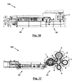
- Figures 16 and 17 depict a horizontal packaging machine 100 comprising a formation module 20 for forming flexible containers 9 and a packaging module 10.
- the flexible containers 9 are manufactured in the formation module 20, for example from continuous sheets of flexible material which are cut, folded and welded to form flexible containers 9 in the form of a pouch, suitable for containing liquid, granulated, ground or powdered products.
- the containers 9 manufactured in the formation module 20 are transferred in a row to the packaging module 10, where the packaging operations, such as opening the container 9, filling it with the product, placing straws and/or stoppers and finally closing the container 9, are performed.
- the packaging module 10 forming part of the horizontal packaging machine 100 depicted in Figures 16 and 17 comprises four rotating operational wheels 1, 2, 3 and 4 of vertical shafts, at least one of which is motor-operated, in this case wheel 1.
- the operational wheels 1, 2, 3 and 4 are provided with corresponding means for carrying out the respective operations on the flexible containers 9, i.e., each operational wheel 1, 2, 3 and 4 forms a station in which a determined operation is carried out on the formed container 9.
- the formed containers 9 are fed into the packaging module 10 in a row, they are seized by respective holding means 7 provided in a drive chain 5 or belt which, linked with the operational wheels 1, 2, 3 and 4, describes a closed trajectory, such that one holding means 7 holds a specific container 9 from the time it is fed into the packaging module 10 and does not release it until the delivery thereof.
- each holding means 7 for the suspension of a flexible container 9 comprises clamps 71 (see Figures 12 , 13 and 14 ) operated by a respective sensing device 72 arranged in the chain 5 which follows a trajectory determined by a cam surface 75 mounted in a static component of the module 10, for example the bedplate 74, such that the separating distance between the ends of the clamps 71 is adjustable depending on the point of the trajectory determined by the cam surface 75 in which its respective sensing device 72 is located.
- the bedplate 74 is a static element on which the vertical shafts of the operational wheels 1 to 4 can be mounted.
- the cam surface 75 in collaboration with the sensing devices 72, serves to move the clamps 71 holding the flexible containers 9 while the chain 5 is in motion, for example, for opening and closing the containers 9.
- the cam surface 75 can also be configured to rotate the clamps 71 to facilitate feeding the containers 9 into the first operational wheel 1.
- the adjustment capacity is determined, among others, by the existence of several oblong holes and elements 73a, 73b and 73c which allow the sliding of the arms of the clamps 71 to move to one side, up, down, to move closer to or farther from one another, according to the point of the trajectory of the cam surface 75 where the sensing device 72 of the clamps 71 in question is located.
- the angle of contact ⁇ of the chain 5 with the operational wheels 1, 2, 3 and 4 is greater than 180°, i.e., the closed trajectory of the chain 5 comprises a series of sectors in which its trajectory coincides with more than half the perimeter of each operational wheel 1, 2, 3 4.
- the packaging module 10 of Figure 17 comprises four deflection wheels 8, each of them arranged outside the closed trajectory of the chain 5 and facing a sector of chain 5 between two adjacent operational wheels 1-2, 2-3, 3-4 and 4-1.
- the arrangement of the deflection wheels 8 in said packaging module 10 is such that when the chain 5 abandons one operational wheel 1, 2, 3 or 4, it immediately links with the deflection wheel 8, an inflection point 6 thus being determined in the trajectory of the chain 5 when its curvature changes direction.
- the chain 5 abandons the deflection wheel 8 it immediately links with the adjacent operational wheel 2, 3, 4 or 1, another inflection point 6 being determined in the trajectory of the chain 5 when its curvature changes direction again.
- FIGS 1 to 8 schematically depict different packaging modules 10, showing the arrangement of the assembly formed by the operational wheels 1-4, the deflection wheels 8 and the chain 5.
- All packaging modules 10 comprise at least two operational wheels 1 and 2 and a drive chain 5 or belt which, linked with them, describes a closed trajectory in which, as previously stated, the angle of contact ⁇ of the chain 5 with the operational wheels 1-4 is greater than 180°.
- the angle of contact ⁇ being greater than 180° is achieved by suitably arranging at least one deflection wheel 8, as is clearly shown in the following examples.
- Figures 1 to 5 schematically depict five packaging modules 10 comprising two operational wheels 1 and 2 and a chain 5 the angle of contact ⁇ of which with the operational wheels 1 and 2 is greater than 180°, and even greater than 260° in some cases (see Figures 3 to 5 ), which contributes to the module 10 being more compact.
- the packaging modules 10 of Figures 1 and 2 further comprise a deflection wheel 8 facing the upper sector of the chain 5 between the operational wheels 1 and 2.
- the difference between the packaging modules 10 of Figures 1 and 2 lies in the closed trajectory of the chain 5 in Figure 2 having two inflection points 6, because when a specific sector of the chain 5 abandons the first operational wheel 1 it then immediately links with the deflection wheel 8, and when it then abandons said deflection wheel 8 it immediately links with the other operational wheel 2.
- FIGs 3 to 5 there are two deflection wheels 8, each of them arranged facing a sector of the chain 5 between the two operational wheels 1 and 2.
- the deflection wheels 8 can have the same size ( Figures 3 and 5 ) or different size ( Figure 4 ) and can be arranged such that the chain 5 immediately links with them when it abandons one operational wheel 1 or 2 in the two sectors of the chain 5 between the two operational wheels 1 and 2 ( Figure 5 ) or in a single sector ( Figure 4 , lower sector).
- the packaging module 10 has more or less stations, which translates into a determined number of operational wheels 1-4 the size of which depends on the means and time necessary for performing a determined packaging operation.
- the packaging modules 10 of Figures 6 and 7 comprise three operational wheels 1, 2 and 3, and module 10 of Figure 8 four operational wheels 1, 2, 3 and 4.
- the operational wheels 1 to 4 are gear wheels the teeth 11 of which are provided with notches 12 in which corresponding pins 51 linking the consecutive links 52 of the chain 5 in an articulated manner mesh or are inserted (see Figure 15 ).
- This structure is shown in module 10 of Figure 9 and in the details of the chain 5 depicted in Figures 10 to 12 .
- the deflection wheels 8 are also gear wheels the teeth 81 of which are provided with notches 82 in which corresponding pins 51 linking the consecutive links 52 of the chain 5 in an articulated manner mesh or are inserted (see Figure 9 ).
- Both the teeth 11 of the operational wheels 1-4 and the teeth 81 of the deflection wheels 8 are interchangeable teeth made of a non-metal material.
- the interchangeable teeth 11 made of non-metal material are attached to the body of the operational wheels 1-4 by screwing plates 13 (only the holes without the screws are depicted in the drawing).
- the plates 13 are not depicted in Figure 10 in order to better see the shape of the interchangeable tooth 11.
- the chain 5 is always centered on the operational wheels 1-4 and on the deflection wheels 8 by means of coupling the pins 51 in the notches 12 and 82, constant maintenance for adjusting it is not necessary, considerable precision in the operations performed on the containers 9 upon their passage through the different operational wheels 1-4 furthermore being ensured.
- the savings in space it entails is clear, as well as the ability of the flexible containers 9 to move at a continuous and constant speed, preventing the content from being about to come out of the container while the relevant operations are performed in the corresponding operational wheels 1, 2, 3 and 4 until closing the container 9, unlike what occurred in earlier packaging modules due to their intermittent movement.
- the speed therefore no longer has to be restricted to prevent the ripple effect, and higher speeds can be reached according to the rate determined by the module 20 for making the containers 9, for example four hundred containers 9 per minute in both modules.
- packaging modules 10 in which one or some of the operational wheels 1, 2, 3 and 4 are arranged outside said trajectory but all the operational wheels 1 to 4 still being linked by the chain 5 and the angle of contact ⁇ of the chain 5 with all of them at all times being greater than 180°, and advantageously greater than 260°, are also contemplated.
Landscapes
- Engineering & Computer Science (AREA)
- Mechanical Engineering (AREA)
- Microelectronics & Electronic Packaging (AREA)
- Supplying Of Containers To The Packaging Station (AREA)
- Wrapping Of Specific Fragile Articles (AREA)
- Auxiliary Devices For And Details Of Packaging Control (AREA)
Claims (11)
- Module de conditionnement (10) pour réaliser au moins deux opérations sur des récipients souples (9) disposés dans une rangée, lesdites opérations étant après la formation effective desdits récipients, telles que l'ouverture, remplissage et/ou fermeture desdits récipients, comprenant :- une chaine de transmission (5) décrivant une trajectoire fermée ;- des moyens de maintien (7) pour la suspension des récipients souples tout le long de leur course complet sont fixés à ladite chaîne de transmission, où chaque moyen de maintien est assigné a la suspension d'un récipient souple correspondant tout le long de sa course, lesdits moyens de maintien étant actionnés par le mouvement relatif de la chaîne par rapport à une autre composant de préférence statique du module ;
caractérisé en ce que le module de conditionnement- comprend au moins deux roues opérationnelles rotatives (1, 2, 3, 4) d'arbres verticaux, dont au moins une est motorisée, lesdites roues opérationnelles étant pourvues de moyens correspondants pour réaliser les opérations respectives sur les récipients ;- où la chaîne de transmission (5) est reliée aux roues opérationnelles ;- où l'angle de contact (α) de la chaîne avec les roues opérationnelles est supérieur à 180°,- où les roues opérationnelles rotatives (1, 2, 3, 4) sont des roues d'engrenage, dont les dents (11) sont pourvues d'entailles (12) dans lesquelles des broches (51) correspondantes reliant les maillons (52) consécutifs de la chaîne (5) sont en prise ou insérées d'une manière articulée, et où le module de conditionnement (10) comprend au moins une roue d'engrenage de déviation (8) disposée en dehors de la trajectoire fermée de la chaîne (5) et en regard d'un secteur de chaîne entre deux roues opérationnelles attenantes (1, 2, 3, 4), les dents (81) de la au moins une roue d'engrenage de déviation étant pourvues d'entailles (82) dans lesquelles des broches (51) correspondantes reliant les maillons (52) consécutifs de la chaîne (5) sont en prise ou insérées d'une manière articulée. - Module de conditionnement (10) selon la revendication 1, caractérisé en ce que les dents (11) des roues opérationnelles (1, 2, 3,4) sont échangeables et réalisées en une matière non métallique.
- Module de conditionnement (10) selon l'une quelconque des revendications précédentes, caractérisé en ce qu'il comprend au moins une roue de déviation (8) disposée en dehors de la trajectoire fermée de la chaîne (5) et en regard d'un secteur de chaîne entre deux roues opérationnelles attenantes (1, 2, 3,4) de manière que lorsque la chaîne quitte une roue opérationnelle, elle est immédiatement relié à la roue de déviation, un point d'inflexion (6) étant déterminé sur la trajectoire de la chaîne lorsque sa courbure change de direction.
- Module de conditionnement (10) selon l'une quelconque des revendications précédentes, caractérisé en ce qu'il comprend au moins une roue de déviation (8) disposée en dehors de la trajectoire fermée de la chaîne (5) et en regard d'un secteur de chaîne entre deux roues opérationnelles attenantes (1, 2, 3,4) de manière que lorsque la chaîne quitte la roue de déviation, elle est immédiatement relié à une roue opérationnelle, un point d'inflexion (6) étant déterminé sur la trajectoire de la chaîne lorsque sa courbure change de direction.
- Module de conditionnement (10) selon l'une quelconque des revendications 3 à 4, caractérisé en ce qu'il comprend autant de roues de déviation (8) que de roues opérationnelles (1, 2, 3, 4) et en ce qu'une roue de déviation est disposée entre chaque paire de roues opérationnelles attenantes en dehors de la trajectoire fermée de la chaîne (5) de manière que lorsque la chaîne quitte une roue opérationnelle, elle est immédiatement relié à une roue de déviation, et lorsque la chaîne quitte ladite roue de déviation, elle est immédiatement relié à la roue opérationnelle attenante à la dernière, des points d'inflexion (6) respectifs étant déterminés sur la trajectoire de la chaîne.
- Module de conditionnement (10) selon l'une quelconque des revendications précédentes, caractérisé en ce que toutes les roues opérationnelles (1, 2, 3, 4) sont disposées au sein de la trajectoire fermée de la chaîne (5).
- Module de conditionnement (10) selon l'une quelconque des revendications précédentes, caractérisé en ce qu'au moins deux roues opérationnelles (1, 2, 3,4) ont des diamètres différents.
- Module de conditionnement (10) selon l'une quelconque des revendications précédentes, caractérisé en ce que l'angle de contact (α) de la chaîne (5) avec les roues opérationnelles (1, 2, 3, 4) est supérieur à 260°.
- Module de conditionnement (10) selon l'une quelconque des revendications précédentes, caractérisé en ce que chaque moyen de maintien (7) pour la suspension d'un récipient souple (9) comprend des attaches (71) actionées par un dispositif de détection (72) respectif disposé sur la chaîne (5) qui suit une trajectoire déterminée par une surface de came (75) fixée au composant de préférence statique du module, de manière que la distance de séparation entre les extrémités des attaches est ajustable en fonction du point de la trajectoire déterminé par la surface de came dans laquelle est situé le dispositif de détection.
- Machine de conditionnement horizontale (100) pourvue d'un module de formation de récipients (20) et un module de conditionnement (10) qui coopèrent de manière que les récipients (9) fabriqués dans le module de formation sont transférés au module de conditionnement dans lequel les opération d'ouverture, remplissage et/ou fermeture des récipients sont réalisés, caractérisée en ce que le module de conditionnement es celui défini dans l'une quelconque des revendications 1 à 10.
- Procédé de conditionnement qui comprend réaliser au moins deux opération sur de récipients souples formés (9) disposés dans une rangée, telles que l'ouverture, remplissage et/ou fermeture desdits récipients, caractérisé en ce qu'il comprend les étapes suivantes :a) maintenir individuellement en suspension chacun des récipients formés dans un moyen de maintien (7) correspondant fixé à une chaîne de transmission (5) ou courroie avec une trajectoire fermée qui à son tour se déplace en continu en avant reliée avec au moins deux roues opérationnelles rotatives (1, 2, 3, 4) d'arbres verticaux, dont au moins une est motorisée, l'angle de contact (α) de la chaîne avec les roues opérationnelles étant supérieur à 180°, où les roues opérationnelles rotatives (1, 2, 3, 4) sont des roues d'engrenage, dont les dents (11) sont pourvues d'entailles (12) dans lesquelles des broches (51) correspondantes reliant les maillons (52) consécutives de la chaîne (5) sont en prise ou insérées d'une manière articulée, où il y a au moins une roue d'engrange de déviation (8) disposée en dehors de la trajectoire fermée de la chaîne (5) et en regard d'un secteur de chaîne entre deux roues opérationnelles attenantes (1, 2, 3, 4), les dents (81) de la au moins une roue d'engrenage de déviation (8) étant pourvues d'entailles (82) dans lesquelles des broches (51) correspondantes reliant les maillons (52) consécutives de la chaîne (5) son en prise ou insérées d'une manière articulée ;b) transporter chaque récipient conduit par la chaîne jusqu'à atteindre un premier point de contact de la chaîne avec la première roue opérationnelle,c) transporter chaque récipient sur plus de la moitié du périmètre de la première roue opérationnelle, en soumettant en même temps chaque récipient à l'action des moyens réalisant la première opération pourvus sur la première roue opérationnelle,d) transporter chaque récipient conduit par la chaîne jusqu'à atteindre un point dans lequel la chaine est dégagée de la première roue opérationnelle,e) transporter chaque récipient conduit par la chaîne jusqu'à atteindre un premier point de contact de la chaîne avec la seconde roue opérationnelle, où la chaîne a été reliée à une roue de déviation entre le point de dégagement de la première roue opérationnelle et le premier point de contact avec la deuxième roue opérationnelle,f) transporter chaque récipient sur plus de la moitié du périmètre de la deuxième roue opérationnel, en soumettant en même temps chaque récipient à l'action des moyens réalisant la deuxième opération pourvus sur la deuxième roue opérationnelle,g) transporter chaque récipient conduit par la chaîne jusqu'à atteindre un point dans lequel la chaîne est dégagée de la deuxième roue opérationnelle,h) libérer individuellement chaque récipient de son moyen de maintien respectif.
Priority Applications (5)
| Application Number | Priority Date | Filing Date | Title |
|---|---|---|---|
| EP11382096.3A EP2508434B1 (fr) | 2011-04-04 | 2011-04-04 | Module de conditionnement, machine et procédé pour réaliser au moins deux opérations sur des récipients souples |
| ES11382096.3T ES2546133T3 (es) | 2011-04-04 | 2011-04-04 | Módulo de envasado, máquina y método para la realización de al menos dos operaciones sobre envases flexibles |
| ES0U ES1093857Y (es) | 2011-04-04 | 2012-04-02 | Módulo de envasado para la realización de al menos dos operaciones sobre envases flexibles. |
| PCT/ES2012/070220 WO2012136869A1 (fr) | 2011-04-04 | 2012-04-02 | Module de conditionnement, machine et procédé de réalisation d'au moins deux opérations sur des emballages flexibles |
| CN201280024875.4A CN103619711B (zh) | 2011-04-04 | 2012-04-02 | 包装模块、包装机器和用于在柔性容器上实施至少两种操作的方法 |
Applications Claiming Priority (1)
| Application Number | Priority Date | Filing Date | Title |
|---|---|---|---|
| EP11382096.3A EP2508434B1 (fr) | 2011-04-04 | 2011-04-04 | Module de conditionnement, machine et procédé pour réaliser au moins deux opérations sur des récipients souples |
Publications (2)
| Publication Number | Publication Date |
|---|---|
| EP2508434A1 EP2508434A1 (fr) | 2012-10-10 |
| EP2508434B1 true EP2508434B1 (fr) | 2015-06-10 |
Family
ID=46147465
Family Applications (1)
| Application Number | Title | Priority Date | Filing Date |
|---|---|---|---|
| EP11382096.3A Not-in-force EP2508434B1 (fr) | 2011-04-04 | 2011-04-04 | Module de conditionnement, machine et procédé pour réaliser au moins deux opérations sur des récipients souples |
Country Status (4)
| Country | Link |
|---|---|
| EP (1) | EP2508434B1 (fr) |
| CN (1) | CN103619711B (fr) |
| ES (2) | ES2546133T3 (fr) |
| WO (1) | WO2012136869A1 (fr) |
Families Citing this family (3)
| Publication number | Priority date | Publication date | Assignee | Title |
|---|---|---|---|---|
| ES2550555T3 (es) * | 2012-10-19 | 2015-11-10 | Volpak, S.A.U. | Procedimiento y dispositivo para la fabricación y llenado en continuo de envases flexibles |
| EP3257764B1 (fr) | 2016-06-15 | 2019-01-30 | Volpak, S.A.U. | Machine de conditionnement automatique permettant de remplir un sac constitué d'un matériau thermoscellable avec une dose d'un produit en vrac |
| EP3395698B1 (fr) | 2017-04-28 | 2021-04-21 | Volpak, S.A.U. | Machine de conditionnement automatique permettant de remplir un sac enmatériau thermoscellable d'une quantité de produit en vrac |
Family Cites Families (13)
| Publication number | Priority date | Publication date | Assignee | Title |
|---|---|---|---|---|
| GB749897A (en) * | 1953-01-05 | 1956-06-06 | Hesser Ag Maschf | Improvements relating to bag-filling and bag-closing machines |
| FR1195550A (fr) * | 1958-05-02 | 1959-11-18 | Materiel D Alimentation Sa Con | Chaîne de manutention pour installation de conditionnement de produits ou denrées en récipients divers |
| JPS5535281B2 (fr) * | 1974-09-04 | 1980-09-12 | ||
| US4531926A (en) * | 1983-07-11 | 1985-07-30 | Reeves Jr James B | Adjustable pitch sprocket |
| SE457433B (sv) * | 1985-08-08 | 1988-12-27 | Mats Ingvar Davidson | Anordning vid transportanlaeggningar |
| DE4035815A1 (de) * | 1990-11-10 | 1992-05-14 | Breitner Abfuellanlagen Gmbh | Anlage zum fuellen von aus folienartigem kunststoffmaterial bestehenden beuteln mit einem fliessfaehigen produkt |
| FR2769608B1 (fr) | 1997-10-14 | 1999-12-31 | Florent Valcalda | Dispositif integre de liaison entre rouleaux elementaires consecutifs de support curviligne pour bande transporteuse souple sans fin d'un convoyeur |
| JP2000281004A (ja) * | 1999-03-31 | 2000-10-10 | Seiko Corp | パウチ充填包装装置およびその方法 |
| ES2226518B1 (es) | 2002-02-20 | 2006-06-01 | Volpak, S.A. | Maquina envasadora automatica. |
| DE10328545B4 (de) * | 2003-06-24 | 2008-08-21 | Sig Technology Ltd. | Vorrichtung und Verfahren zum Betreiben von kontinuierlich auf Trägerelementen bereitgestellten Packungen |
| ES2257180B1 (es) | 2004-10-13 | 2007-08-16 | Volpak, S.A. | Dispositivo de transporte de envases. |
| CN2926673Y (zh) * | 2006-05-30 | 2007-07-25 | 方若宇 | 一种链条式行星传动机构 |
| CN101579918A (zh) * | 2009-04-23 | 2009-11-18 | 林子祥 | 瓶坯输送装置 |
-
2011
- 2011-04-04 ES ES11382096.3T patent/ES2546133T3/es active Active
- 2011-04-04 EP EP11382096.3A patent/EP2508434B1/fr not_active Not-in-force
-
2012
- 2012-04-02 ES ES0U patent/ES1093857Y/es not_active Expired - Fee Related
- 2012-04-02 CN CN201280024875.4A patent/CN103619711B/zh not_active Expired - Fee Related
- 2012-04-02 WO PCT/ES2012/070220 patent/WO2012136869A1/fr active Application Filing
Also Published As
| Publication number | Publication date |
|---|---|
| CN103619711B (zh) | 2015-08-19 |
| ES1093857Y (es) | 2014-02-18 |
| EP2508434A1 (fr) | 2012-10-10 |
| WO2012136869A1 (fr) | 2012-10-11 |
| CN103619711A (zh) | 2014-03-05 |
| ES1093857U (es) | 2013-11-25 |
| ES2546133T3 (es) | 2015-09-18 |
Similar Documents
| Publication | Publication Date | Title |
|---|---|---|
| EP2998232B1 (fr) | Dispositif pour le transport dans une ligne de conditionnement de contenants souples maintenus suspendus | |
| US7264113B2 (en) | Pivotable conveyor and link | |
| US9254967B2 (en) | Module for aligning containers and method for aligning containers | |
| US20050284735A1 (en) | Flexible conveyor and connection elements | |
| EP2671807B1 (fr) | Appareil pour transférer des produits pharmaceutiques d'un appareil de comptage vers des conteneurs avançant en continu | |
| EP3269654A1 (fr) | Poste de travail pour chaîne d'emballage et chaîne d'emballage comprenant au moins deux postes de travail de ce type | |
| US20050108992A1 (en) | Beverage bottling plant for filling bottles with a liquid beverage filling material, having a separating and compacting device | |
| CN1576197B (zh) | 无链式容器搬送装置 | |
| EP2998229B1 (fr) | Procédé pour le transport dans une ligne de conditionnement de contenants souples retenus et suspendus, dispositif approprié pour la mise en pratique du procédé et machine comprenant ce dispositif | |
| WO2006052251A1 (fr) | Transporteur saisissant des cols et liaison, et systeme de remplissage rotatif associe | |
| EP2508434B1 (fr) | Module de conditionnement, machine et procédé pour réaliser au moins deux opérations sur des récipients souples | |
| JPH07110655B2 (ja) | パック−乃至アンパック機械 | |
| CN109890707B (zh) | 用于将产品包装在预制包装中的设备和方法 | |
| EP2846756B1 (fr) | Dispositif pour le remplissage de capsules | |
| US20070000206A1 (en) | Device for continuously filling and closing composite cardboard/plastic packagings opened on one side and cell cage for transporting said packagings in the device | |
| EP3254994A1 (fr) | Roue de transport servant à transporter des articles et appareil de manipulation d'articles comprenant au moins une telle roue | |
| ES2836288T3 (es) | Aparato de reorientación de piezas de cigarrillos simulados | |
| JP4307978B2 (ja) | 容器の搬送装置 | |
| JP4274895B2 (ja) | 容器整列装置 | |
| JP4229801B2 (ja) | 容器搬送装置 | |
| JP3380917B2 (ja) | ボトリングシステム | |
| KR200464716Y1 (ko) | 용기 이송장치 | |
| CN201390643Y (zh) | 容器的夹持输送装置 | |
| JP2009215084A (ja) | 容器の搬送装置 | |
| JP2022533849A (ja) | 特に製薬産業におけるボトルを充填する装置のための搬送方法及び搬送システム |
Legal Events
| Date | Code | Title | Description |
|---|---|---|---|
| PUAI | Public reference made under article 153(3) epc to a published international application that has entered the european phase |
Free format text: ORIGINAL CODE: 0009012 |
|
| AK | Designated contracting states |
Kind code of ref document: A1 Designated state(s): AL AT BE BG CH CY CZ DE DK EE ES FI FR GB GR HR HU IE IS IT LI LT LU LV MC MK MT NL NO PL PT RO RS SE SI SK SM TR |
|
| AX | Request for extension of the european patent |
Extension state: BA ME |
|
| 17P | Request for examination filed |
Effective date: 20130311 |
|
| 17Q | First examination report despatched |
Effective date: 20130731 |
|
| GRAP | Despatch of communication of intention to grant a patent |
Free format text: ORIGINAL CODE: EPIDOSNIGR1 |
|
| INTG | Intention to grant announced |
Effective date: 20150128 |
|
| GRAS | Grant fee paid |
Free format text: ORIGINAL CODE: EPIDOSNIGR3 |
|
| GRAA | (expected) grant |
Free format text: ORIGINAL CODE: 0009210 |
|
| AK | Designated contracting states |
Kind code of ref document: B1 Designated state(s): AL AT BE BG CH CY CZ DE DK EE ES FI FR GB GR HR HU IE IS IT LI LT LU LV MC MK MT NL NO PL PT RO RS SE SI SK SM TR |
|
| REG | Reference to a national code |
Ref country code: GB Ref legal event code: FG4D |
|
| REG | Reference to a national code |
Ref country code: CH Ref legal event code: EP |
|
| REG | Reference to a national code |
Ref country code: AT Ref legal event code: REF Ref document number: 730795 Country of ref document: AT Kind code of ref document: T Effective date: 20150715 |
|
| REG | Reference to a national code |
Ref country code: DE Ref legal event code: R096 Ref document number: 602011017039 Country of ref document: DE |
|
| REG | Reference to a national code |
Ref country code: IE Ref legal event code: FG4D |
|
| REG | Reference to a national code |
Ref country code: ES Ref legal event code: FG2A Ref document number: 2546133 Country of ref document: ES Kind code of ref document: T3 Effective date: 20150918 |
|
| PG25 | Lapsed in a contracting state [announced via postgrant information from national office to epo] |
Ref country code: LT Free format text: LAPSE BECAUSE OF FAILURE TO SUBMIT A TRANSLATION OF THE DESCRIPTION OR TO PAY THE FEE WITHIN THE PRESCRIBED TIME-LIMIT Effective date: 20150610 Ref country code: NO Free format text: LAPSE BECAUSE OF FAILURE TO SUBMIT A TRANSLATION OF THE DESCRIPTION OR TO PAY THE FEE WITHIN THE PRESCRIBED TIME-LIMIT Effective date: 20150910 Ref country code: FI Free format text: LAPSE BECAUSE OF FAILURE TO SUBMIT A TRANSLATION OF THE DESCRIPTION OR TO PAY THE FEE WITHIN THE PRESCRIBED TIME-LIMIT Effective date: 20150610 |
|
| REG | Reference to a national code |
Ref country code: AT Ref legal event code: MK05 Ref document number: 730795 Country of ref document: AT Kind code of ref document: T Effective date: 20150610 |
|
| REG | Reference to a national code |
Ref country code: NL Ref legal event code: MP Effective date: 20150610 |
|
| PG25 | Lapsed in a contracting state [announced via postgrant information from national office to epo] |
Ref country code: GR Free format text: LAPSE BECAUSE OF FAILURE TO SUBMIT A TRANSLATION OF THE DESCRIPTION OR TO PAY THE FEE WITHIN THE PRESCRIBED TIME-LIMIT Effective date: 20150911 Ref country code: BG Free format text: LAPSE BECAUSE OF FAILURE TO SUBMIT A TRANSLATION OF THE DESCRIPTION OR TO PAY THE FEE WITHIN THE PRESCRIBED TIME-LIMIT Effective date: 20150910 Ref country code: LV Free format text: LAPSE BECAUSE OF FAILURE TO SUBMIT A TRANSLATION OF THE DESCRIPTION OR TO PAY THE FEE WITHIN THE PRESCRIBED TIME-LIMIT Effective date: 20150610 Ref country code: RS Free format text: LAPSE BECAUSE OF FAILURE TO SUBMIT A TRANSLATION OF THE DESCRIPTION OR TO PAY THE FEE WITHIN THE PRESCRIBED TIME-LIMIT Effective date: 20150610 |
|
| PG25 | Lapsed in a contracting state [announced via postgrant information from national office to epo] |
Ref country code: EE Free format text: LAPSE BECAUSE OF FAILURE TO SUBMIT A TRANSLATION OF THE DESCRIPTION OR TO PAY THE FEE WITHIN THE PRESCRIBED TIME-LIMIT Effective date: 20150610 |
|
| PG25 | Lapsed in a contracting state [announced via postgrant information from national office to epo] |
Ref country code: AT Free format text: LAPSE BECAUSE OF FAILURE TO SUBMIT A TRANSLATION OF THE DESCRIPTION OR TO PAY THE FEE WITHIN THE PRESCRIBED TIME-LIMIT Effective date: 20150610 Ref country code: CZ Free format text: LAPSE BECAUSE OF FAILURE TO SUBMIT A TRANSLATION OF THE DESCRIPTION OR TO PAY THE FEE WITHIN THE PRESCRIBED TIME-LIMIT Effective date: 20150610 Ref country code: RO Free format text: LAPSE BECAUSE OF NON-PAYMENT OF DUE FEES Effective date: 20150610 Ref country code: PT Free format text: LAPSE BECAUSE OF FAILURE TO SUBMIT A TRANSLATION OF THE DESCRIPTION OR TO PAY THE FEE WITHIN THE PRESCRIBED TIME-LIMIT Effective date: 20151012 Ref country code: PL Free format text: LAPSE BECAUSE OF FAILURE TO SUBMIT A TRANSLATION OF THE DESCRIPTION OR TO PAY THE FEE WITHIN THE PRESCRIBED TIME-LIMIT Effective date: 20150610 Ref country code: SK Free format text: LAPSE BECAUSE OF FAILURE TO SUBMIT A TRANSLATION OF THE DESCRIPTION OR TO PAY THE FEE WITHIN THE PRESCRIBED TIME-LIMIT Effective date: 20150610 Ref country code: IS Free format text: LAPSE BECAUSE OF FAILURE TO SUBMIT A TRANSLATION OF THE DESCRIPTION OR TO PAY THE FEE WITHIN THE PRESCRIBED TIME-LIMIT Effective date: 20151010 |
|
| REG | Reference to a national code |
Ref country code: DE Ref legal event code: R097 Ref document number: 602011017039 Country of ref document: DE |
|
| PLBE | No opposition filed within time limit |
Free format text: ORIGINAL CODE: 0009261 |
|
| STAA | Information on the status of an ep patent application or granted ep patent |
Free format text: STATUS: NO OPPOSITION FILED WITHIN TIME LIMIT |
|
| REG | Reference to a national code |
Ref country code: FR Ref legal event code: PLFP Year of fee payment: 6 |
|
| PG25 | Lapsed in a contracting state [announced via postgrant information from national office to epo] |
Ref country code: DK Free format text: LAPSE BECAUSE OF FAILURE TO SUBMIT A TRANSLATION OF THE DESCRIPTION OR TO PAY THE FEE WITHIN THE PRESCRIBED TIME-LIMIT Effective date: 20150610 |
|
| 26N | No opposition filed |
Effective date: 20160311 |
|
| PG25 | Lapsed in a contracting state [announced via postgrant information from national office to epo] |
Ref country code: SI Free format text: LAPSE BECAUSE OF FAILURE TO SUBMIT A TRANSLATION OF THE DESCRIPTION OR TO PAY THE FEE WITHIN THE PRESCRIBED TIME-LIMIT Effective date: 20150610 |
|
| PG25 | Lapsed in a contracting state [announced via postgrant information from national office to epo] |
Ref country code: BE Free format text: LAPSE BECAUSE OF NON-PAYMENT OF DUE FEES Effective date: 20160430 |
|
| REG | Reference to a national code |
Ref country code: CH Ref legal event code: PL |
|
| GBPC | Gb: european patent ceased through non-payment of renewal fee |
Effective date: 20160404 |
|
| PG25 | Lapsed in a contracting state [announced via postgrant information from national office to epo] |
Ref country code: BE Free format text: LAPSE BECAUSE OF FAILURE TO SUBMIT A TRANSLATION OF THE DESCRIPTION OR TO PAY THE FEE WITHIN THE PRESCRIBED TIME-LIMIT Effective date: 20150610 Ref country code: LU Free format text: LAPSE BECAUSE OF FAILURE TO SUBMIT A TRANSLATION OF THE DESCRIPTION OR TO PAY THE FEE WITHIN THE PRESCRIBED TIME-LIMIT Effective date: 20160404 |
|
| REG | Reference to a national code |
Ref country code: IE Ref legal event code: MM4A |
|
| PG25 | Lapsed in a contracting state [announced via postgrant information from national office to epo] |
Ref country code: LI Free format text: LAPSE BECAUSE OF NON-PAYMENT OF DUE FEES Effective date: 20160430 Ref country code: GB Free format text: LAPSE BECAUSE OF NON-PAYMENT OF DUE FEES Effective date: 20160404 Ref country code: CH Free format text: LAPSE BECAUSE OF NON-PAYMENT OF DUE FEES Effective date: 20160430 |
|
| REG | Reference to a national code |
Ref country code: FR Ref legal event code: PLFP Year of fee payment: 7 |
|
| PG25 | Lapsed in a contracting state [announced via postgrant information from national office to epo] |
Ref country code: IE Free format text: LAPSE BECAUSE OF NON-PAYMENT OF DUE FEES Effective date: 20160404 |
|
| PG25 | Lapsed in a contracting state [announced via postgrant information from national office to epo] |
Ref country code: SE Free format text: LAPSE BECAUSE OF FAILURE TO SUBMIT A TRANSLATION OF THE DESCRIPTION OR TO PAY THE FEE WITHIN THE PRESCRIBED TIME-LIMIT Effective date: 20150610 Ref country code: NL Free format text: LAPSE BECAUSE OF FAILURE TO SUBMIT A TRANSLATION OF THE DESCRIPTION OR TO PAY THE FEE WITHIN THE PRESCRIBED TIME-LIMIT Effective date: 20150610 |
|
| REG | Reference to a national code |
Ref country code: FR Ref legal event code: PLFP Year of fee payment: 8 |
|
| PG25 | Lapsed in a contracting state [announced via postgrant information from national office to epo] |
Ref country code: SM Free format text: LAPSE BECAUSE OF FAILURE TO SUBMIT A TRANSLATION OF THE DESCRIPTION OR TO PAY THE FEE WITHIN THE PRESCRIBED TIME-LIMIT Effective date: 20150610 Ref country code: HU Free format text: LAPSE BECAUSE OF FAILURE TO SUBMIT A TRANSLATION OF THE DESCRIPTION OR TO PAY THE FEE WITHIN THE PRESCRIBED TIME-LIMIT; INVALID AB INITIO Effective date: 20110404 Ref country code: CY Free format text: LAPSE BECAUSE OF FAILURE TO SUBMIT A TRANSLATION OF THE DESCRIPTION OR TO PAY THE FEE WITHIN THE PRESCRIBED TIME-LIMIT Effective date: 20150610 |
|
| PG25 | Lapsed in a contracting state [announced via postgrant information from national office to epo] |
Ref country code: MK Free format text: LAPSE BECAUSE OF FAILURE TO SUBMIT A TRANSLATION OF THE DESCRIPTION OR TO PAY THE FEE WITHIN THE PRESCRIBED TIME-LIMIT Effective date: 20150610 Ref country code: MC Free format text: LAPSE BECAUSE OF FAILURE TO SUBMIT A TRANSLATION OF THE DESCRIPTION OR TO PAY THE FEE WITHIN THE PRESCRIBED TIME-LIMIT Effective date: 20150610 Ref country code: HR Free format text: LAPSE BECAUSE OF FAILURE TO SUBMIT A TRANSLATION OF THE DESCRIPTION OR TO PAY THE FEE WITHIN THE PRESCRIBED TIME-LIMIT Effective date: 20150610 Ref country code: MT Free format text: LAPSE BECAUSE OF NON-PAYMENT OF DUE FEES Effective date: 20160430 Ref country code: TR Free format text: LAPSE BECAUSE OF FAILURE TO SUBMIT A TRANSLATION OF THE DESCRIPTION OR TO PAY THE FEE WITHIN THE PRESCRIBED TIME-LIMIT Effective date: 20150610 |
|
| PG25 | Lapsed in a contracting state [announced via postgrant information from national office to epo] |
Ref country code: AL Free format text: LAPSE BECAUSE OF FAILURE TO SUBMIT A TRANSLATION OF THE DESCRIPTION OR TO PAY THE FEE WITHIN THE PRESCRIBED TIME-LIMIT Effective date: 20150610 |
|
| PGFP | Annual fee paid to national office [announced via postgrant information from national office to epo] |
Ref country code: ES Payment date: 20190503 Year of fee payment: 9 Ref country code: IT Payment date: 20190423 Year of fee payment: 9 Ref country code: DE Payment date: 20190429 Year of fee payment: 9 |
|
| PGFP | Annual fee paid to national office [announced via postgrant information from national office to epo] |
Ref country code: FR Payment date: 20190425 Year of fee payment: 9 |
|
| REG | Reference to a national code |
Ref country code: DE Ref legal event code: R119 Ref document number: 602011017039 Country of ref document: DE |
|
| PG25 | Lapsed in a contracting state [announced via postgrant information from national office to epo] |
Ref country code: FR Free format text: LAPSE BECAUSE OF NON-PAYMENT OF DUE FEES Effective date: 20200430 Ref country code: DE Free format text: LAPSE BECAUSE OF NON-PAYMENT OF DUE FEES Effective date: 20201103 |
|
| REG | Reference to a national code |
Ref country code: ES Ref legal event code: FD2A Effective date: 20210826 |
|
| PG25 | Lapsed in a contracting state [announced via postgrant information from national office to epo] |
Ref country code: IT Free format text: LAPSE BECAUSE OF NON-PAYMENT OF DUE FEES Effective date: 20200404 |
|
| PG25 | Lapsed in a contracting state [announced via postgrant information from national office to epo] |
Ref country code: ES Free format text: LAPSE BECAUSE OF NON-PAYMENT OF DUE FEES Effective date: 20200405 |