EP2505947A1 - Verfahren und Vorrichtung zur Erzeugung von Floatglas - Google Patents
Verfahren und Vorrichtung zur Erzeugung von Floatglas Download PDFInfo
- Publication number
- EP2505947A1 EP2505947A1 EP11004356A EP11004356A EP2505947A1 EP 2505947 A1 EP2505947 A1 EP 2505947A1 EP 11004356 A EP11004356 A EP 11004356A EP 11004356 A EP11004356 A EP 11004356A EP 2505947 A1 EP2505947 A1 EP 2505947A1
- Authority
- EP
- European Patent Office
- Prior art keywords
- oxygen
- nitrogen
- gas mixture
- product
- column
- Prior art date
- Legal status (The legal status is an assumption and is not a legal conclusion. Google has not performed a legal analysis and makes no representation as to the accuracy of the status listed.)
- Withdrawn
Links
- 238000000034 method Methods 0.000 title claims abstract description 21
- IJGRMHOSHXDMSA-UHFFFAOYSA-N Atomic nitrogen Chemical compound N#N IJGRMHOSHXDMSA-UHFFFAOYSA-N 0.000 claims abstract description 98
- 229910052757 nitrogen Inorganic materials 0.000 claims abstract description 47
- 239000001301 oxygen Substances 0.000 claims abstract description 44
- 229910052760 oxygen Inorganic materials 0.000 claims abstract description 44
- QVGXLLKOCUKJST-UHFFFAOYSA-N atomic oxygen Chemical compound [O] QVGXLLKOCUKJST-UHFFFAOYSA-N 0.000 claims abstract description 43
- 239000007789 gas Substances 0.000 claims abstract description 37
- 238000000926 separation method Methods 0.000 claims abstract description 33
- 239000000203 mixture Substances 0.000 claims abstract description 30
- 239000005329 float glass Substances 0.000 claims abstract description 22
- 239000011521 glass Substances 0.000 claims abstract description 14
- 239000000446 fuel Substances 0.000 claims abstract description 6
- 229910052739 hydrogen Inorganic materials 0.000 claims abstract description 6
- 239000001257 hydrogen Substances 0.000 claims abstract description 6
- 238000002360 preparation method Methods 0.000 claims abstract description 5
- 239000002994 raw material Substances 0.000 claims abstract description 5
- 239000006060 molten glass Substances 0.000 claims abstract description 4
- 239000000156 glass melt Substances 0.000 claims abstract 4
- 125000004435 hydrogen atom Chemical class [H]* 0.000 claims abstract 3
- 238000002156 mixing Methods 0.000 claims description 22
- 238000004821 distillation Methods 0.000 claims description 5
- MYMOFIZGZYHOMD-UHFFFAOYSA-N Dioxygen Chemical compound O=O MYMOFIZGZYHOMD-UHFFFAOYSA-N 0.000 claims description 4
- 238000002844 melting Methods 0.000 claims description 4
- 230000008018 melting Effects 0.000 claims description 4
- DOTMOQHOJINYBL-UHFFFAOYSA-N molecular nitrogen;molecular oxygen Chemical compound N#N.O=O DOTMOQHOJINYBL-UHFFFAOYSA-N 0.000 claims description 4
- 238000004519 manufacturing process Methods 0.000 description 14
- 239000007788 liquid Substances 0.000 description 13
- 239000012535 impurity Substances 0.000 description 4
- UFHFLCQGNIYNRP-UHFFFAOYSA-N Hydrogen Chemical compound [H][H] UFHFLCQGNIYNRP-UHFFFAOYSA-N 0.000 description 3
- MWUXSHHQAYIFBG-UHFFFAOYSA-N Nitric oxide Chemical compound O=[N] MWUXSHHQAYIFBG-UHFFFAOYSA-N 0.000 description 3
- 230000006835 compression Effects 0.000 description 3
- 238000007906 compression Methods 0.000 description 3
- CURLTUGMZLYLDI-UHFFFAOYSA-N Carbon dioxide Chemical compound O=C=O CURLTUGMZLYLDI-UHFFFAOYSA-N 0.000 description 2
- 238000006124 Pilkington process Methods 0.000 description 2
- ATJFFYVFTNAWJD-UHFFFAOYSA-N Tin Chemical compound [Sn] ATJFFYVFTNAWJD-UHFFFAOYSA-N 0.000 description 2
- 238000004887 air purification Methods 0.000 description 2
- 239000003990 capacitor Substances 0.000 description 2
- 239000005357 flat glass Substances 0.000 description 2
- 238000010992 reflux Methods 0.000 description 2
- 238000004781 supercooling Methods 0.000 description 2
- XLYOFNOQVPJJNP-UHFFFAOYSA-N water Substances O XLYOFNOQVPJJNP-UHFFFAOYSA-N 0.000 description 2
- QJGQUHMNIGDVPM-BJUDXGSMSA-N Nitrogen-13 Chemical compound [13N] QJGQUHMNIGDVPM-BJUDXGSMSA-N 0.000 description 1
- 229910002092 carbon dioxide Inorganic materials 0.000 description 1
- 239000001569 carbon dioxide Substances 0.000 description 1
- 238000002485 combustion reaction Methods 0.000 description 1
- 239000000470 constituent Substances 0.000 description 1
- 238000001816 cooling Methods 0.000 description 1
- 230000001419 dependent effect Effects 0.000 description 1
- 239000000428 dust Substances 0.000 description 1
- 238000005265 energy consumption Methods 0.000 description 1
- 230000002349 favourable effect Effects 0.000 description 1
- 238000010438 heat treatment Methods 0.000 description 1
- 239000011261 inert gas Substances 0.000 description 1
- 239000002184 metal Substances 0.000 description 1
- QJGQUHMNIGDVPM-OUBTZVSYSA-N nitrogen-15 Chemical compound [15N] QJGQUHMNIGDVPM-OUBTZVSYSA-N 0.000 description 1
- 230000003647 oxidation Effects 0.000 description 1
- 238000007254 oxidation reaction Methods 0.000 description 1
- 238000010926 purge Methods 0.000 description 1
- 238000005057 refrigeration Methods 0.000 description 1
- 230000008929 regeneration Effects 0.000 description 1
- 238000011069 regeneration method Methods 0.000 description 1
- 230000003068 static effect Effects 0.000 description 1
- 238000003860 storage Methods 0.000 description 1
- 239000000126 substance Substances 0.000 description 1
Images
Classifications
-
- F—MECHANICAL ENGINEERING; LIGHTING; HEATING; WEAPONS; BLASTING
- F25—REFRIGERATION OR COOLING; COMBINED HEATING AND REFRIGERATION SYSTEMS; HEAT PUMP SYSTEMS; MANUFACTURE OR STORAGE OF ICE; LIQUEFACTION SOLIDIFICATION OF GASES
- F25J—LIQUEFACTION, SOLIDIFICATION OR SEPARATION OF GASES OR GASEOUS OR LIQUEFIED GASEOUS MIXTURES BY PRESSURE AND COLD TREATMENT OR BY BRINGING THEM INTO THE SUPERCRITICAL STATE
- F25J3/00—Processes or apparatus for separating the constituents of gaseous or liquefied gaseous mixtures involving the use of liquefaction or solidification
- F25J3/02—Processes or apparatus for separating the constituents of gaseous or liquefied gaseous mixtures involving the use of liquefaction or solidification by rectification, i.e. by continuous interchange of heat and material between a vapour stream and a liquid stream
- F25J3/04—Processes or apparatus for separating the constituents of gaseous or liquefied gaseous mixtures involving the use of liquefaction or solidification by rectification, i.e. by continuous interchange of heat and material between a vapour stream and a liquid stream for air
- F25J3/04248—Generation of cold for compensating heat leaks or liquid production, e.g. by Joule-Thompson expansion
- F25J3/04284—Generation of cold for compensating heat leaks or liquid production, e.g. by Joule-Thompson expansion using internal refrigeration by open-loop gas work expansion, e.g. of intermediate or oxygen enriched (waste-)streams
- F25J3/0429—Generation of cold for compensating heat leaks or liquid production, e.g. by Joule-Thompson expansion using internal refrigeration by open-loop gas work expansion, e.g. of intermediate or oxygen enriched (waste-)streams of feed air, e.g. used as waste or product air or expanded into an auxiliary column
- F25J3/04303—Lachmann expansion, i.e. expanded into oxygen producing or low pressure column
-
- C—CHEMISTRY; METALLURGY
- C03—GLASS; MINERAL OR SLAG WOOL
- C03B—MANUFACTURE, SHAPING, OR SUPPLEMENTARY PROCESSES
- C03B18/00—Shaping glass in contact with the surface of a liquid
- C03B18/02—Forming sheets
- C03B18/20—Composition of the atmosphere above the float bath; Treating or purifying the atmosphere above the float bath
-
- C—CHEMISTRY; METALLURGY
- C03—GLASS; MINERAL OR SLAG WOOL
- C03B—MANUFACTURE, SHAPING, OR SUPPLEMENTARY PROCESSES
- C03B5/00—Melting in furnaces; Furnaces so far as specially adapted for glass manufacture
- C03B5/16—Special features of the melting process; Auxiliary means specially adapted for glass-melting furnaces
- C03B5/235—Heating the glass
- C03B5/2353—Heating the glass by combustion with pure oxygen or oxygen-enriched air, e.g. using oxy-fuel burners or oxygen lances
-
- F—MECHANICAL ENGINEERING; LIGHTING; HEATING; WEAPONS; BLASTING
- F25—REFRIGERATION OR COOLING; COMBINED HEATING AND REFRIGERATION SYSTEMS; HEAT PUMP SYSTEMS; MANUFACTURE OR STORAGE OF ICE; LIQUEFACTION SOLIDIFICATION OF GASES
- F25J—LIQUEFACTION, SOLIDIFICATION OR SEPARATION OF GASES OR GASEOUS OR LIQUEFIED GASEOUS MIXTURES BY PRESSURE AND COLD TREATMENT OR BY BRINGING THEM INTO THE SUPERCRITICAL STATE
- F25J3/00—Processes or apparatus for separating the constituents of gaseous or liquefied gaseous mixtures involving the use of liquefaction or solidification
- F25J3/02—Processes or apparatus for separating the constituents of gaseous or liquefied gaseous mixtures involving the use of liquefaction or solidification by rectification, i.e. by continuous interchange of heat and material between a vapour stream and a liquid stream
- F25J3/04—Processes or apparatus for separating the constituents of gaseous or liquefied gaseous mixtures involving the use of liquefaction or solidification by rectification, i.e. by continuous interchange of heat and material between a vapour stream and a liquid stream for air
- F25J3/04248—Generation of cold for compensating heat leaks or liquid production, e.g. by Joule-Thompson expansion
- F25J3/04284—Generation of cold for compensating heat leaks or liquid production, e.g. by Joule-Thompson expansion using internal refrigeration by open-loop gas work expansion, e.g. of intermediate or oxygen enriched (waste-)streams
- F25J3/0429—Generation of cold for compensating heat leaks or liquid production, e.g. by Joule-Thompson expansion using internal refrigeration by open-loop gas work expansion, e.g. of intermediate or oxygen enriched (waste-)streams of feed air, e.g. used as waste or product air or expanded into an auxiliary column
-
- F—MECHANICAL ENGINEERING; LIGHTING; HEATING; WEAPONS; BLASTING
- F25—REFRIGERATION OR COOLING; COMBINED HEATING AND REFRIGERATION SYSTEMS; HEAT PUMP SYSTEMS; MANUFACTURE OR STORAGE OF ICE; LIQUEFACTION SOLIDIFICATION OF GASES
- F25J—LIQUEFACTION, SOLIDIFICATION OR SEPARATION OF GASES OR GASEOUS OR LIQUEFIED GASEOUS MIXTURES BY PRESSURE AND COLD TREATMENT OR BY BRINGING THEM INTO THE SUPERCRITICAL STATE
- F25J3/00—Processes or apparatus for separating the constituents of gaseous or liquefied gaseous mixtures involving the use of liquefaction or solidification
- F25J3/02—Processes or apparatus for separating the constituents of gaseous or liquefied gaseous mixtures involving the use of liquefaction or solidification by rectification, i.e. by continuous interchange of heat and material between a vapour stream and a liquid stream
- F25J3/04—Processes or apparatus for separating the constituents of gaseous or liquefied gaseous mixtures involving the use of liquefaction or solidification by rectification, i.e. by continuous interchange of heat and material between a vapour stream and a liquid stream for air
- F25J3/04248—Generation of cold for compensating heat leaks or liquid production, e.g. by Joule-Thompson expansion
- F25J3/04375—Details relating to the work expansion, e.g. process parameter etc.
- F25J3/04393—Details relating to the work expansion, e.g. process parameter etc. using multiple or multistage gas work expansion
-
- F—MECHANICAL ENGINEERING; LIGHTING; HEATING; WEAPONS; BLASTING
- F25—REFRIGERATION OR COOLING; COMBINED HEATING AND REFRIGERATION SYSTEMS; HEAT PUMP SYSTEMS; MANUFACTURE OR STORAGE OF ICE; LIQUEFACTION SOLIDIFICATION OF GASES
- F25J—LIQUEFACTION, SOLIDIFICATION OR SEPARATION OF GASES OR GASEOUS OR LIQUEFIED GASEOUS MIXTURES BY PRESSURE AND COLD TREATMENT OR BY BRINGING THEM INTO THE SUPERCRITICAL STATE
- F25J3/00—Processes or apparatus for separating the constituents of gaseous or liquefied gaseous mixtures involving the use of liquefaction or solidification
- F25J3/02—Processes or apparatus for separating the constituents of gaseous or liquefied gaseous mixtures involving the use of liquefaction or solidification by rectification, i.e. by continuous interchange of heat and material between a vapour stream and a liquid stream
- F25J3/04—Processes or apparatus for separating the constituents of gaseous or liquefied gaseous mixtures involving the use of liquefaction or solidification by rectification, i.e. by continuous interchange of heat and material between a vapour stream and a liquid stream for air
- F25J3/0446—Processes or apparatus for separating the constituents of gaseous or liquefied gaseous mixtures involving the use of liquefaction or solidification by rectification, i.e. by continuous interchange of heat and material between a vapour stream and a liquid stream for air using the heat generated by mixing two different phases
- F25J3/04466—Processes or apparatus for separating the constituents of gaseous or liquefied gaseous mixtures involving the use of liquefaction or solidification by rectification, i.e. by continuous interchange of heat and material between a vapour stream and a liquid stream for air using the heat generated by mixing two different phases for producing oxygen as a mixing column overhead gas by mixing gaseous air feed and liquid oxygen
-
- F—MECHANICAL ENGINEERING; LIGHTING; HEATING; WEAPONS; BLASTING
- F25—REFRIGERATION OR COOLING; COMBINED HEATING AND REFRIGERATION SYSTEMS; HEAT PUMP SYSTEMS; MANUFACTURE OR STORAGE OF ICE; LIQUEFACTION SOLIDIFICATION OF GASES
- F25J—LIQUEFACTION, SOLIDIFICATION OR SEPARATION OF GASES OR GASEOUS OR LIQUEFIED GASEOUS MIXTURES BY PRESSURE AND COLD TREATMENT OR BY BRINGING THEM INTO THE SUPERCRITICAL STATE
- F25J3/00—Processes or apparatus for separating the constituents of gaseous or liquefied gaseous mixtures involving the use of liquefaction or solidification
- F25J3/02—Processes or apparatus for separating the constituents of gaseous or liquefied gaseous mixtures involving the use of liquefaction or solidification by rectification, i.e. by continuous interchange of heat and material between a vapour stream and a liquid stream
- F25J3/04—Processes or apparatus for separating the constituents of gaseous or liquefied gaseous mixtures involving the use of liquefaction or solidification by rectification, i.e. by continuous interchange of heat and material between a vapour stream and a liquid stream for air
- F25J3/04521—Coupling of the air fractionation unit to an air gas-consuming unit, so-called integrated processes
- F25J3/04527—Integration with an oxygen consuming unit, e.g. glass facility, waste incineration or oxygen based processes in general
-
- F—MECHANICAL ENGINEERING; LIGHTING; HEATING; WEAPONS; BLASTING
- F25—REFRIGERATION OR COOLING; COMBINED HEATING AND REFRIGERATION SYSTEMS; HEAT PUMP SYSTEMS; MANUFACTURE OR STORAGE OF ICE; LIQUEFACTION SOLIDIFICATION OF GASES
- F25J—LIQUEFACTION, SOLIDIFICATION OR SEPARATION OF GASES OR GASEOUS OR LIQUEFIED GASEOUS MIXTURES BY PRESSURE AND COLD TREATMENT OR BY BRINGING THEM INTO THE SUPERCRITICAL STATE
- F25J3/00—Processes or apparatus for separating the constituents of gaseous or liquefied gaseous mixtures involving the use of liquefaction or solidification
- F25J3/02—Processes or apparatus for separating the constituents of gaseous or liquefied gaseous mixtures involving the use of liquefaction or solidification by rectification, i.e. by continuous interchange of heat and material between a vapour stream and a liquid stream
- F25J3/04—Processes or apparatus for separating the constituents of gaseous or liquefied gaseous mixtures involving the use of liquefaction or solidification by rectification, i.e. by continuous interchange of heat and material between a vapour stream and a liquid stream for air
- F25J3/04521—Coupling of the air fractionation unit to an air gas-consuming unit, so-called integrated processes
- F25J3/04563—Integration with a nitrogen consuming unit, e.g. for purging, inerting, cooling or heating
-
- F—MECHANICAL ENGINEERING; LIGHTING; HEATING; WEAPONS; BLASTING
- F25—REFRIGERATION OR COOLING; COMBINED HEATING AND REFRIGERATION SYSTEMS; HEAT PUMP SYSTEMS; MANUFACTURE OR STORAGE OF ICE; LIQUEFACTION SOLIDIFICATION OF GASES
- F25J—LIQUEFACTION, SOLIDIFICATION OR SEPARATION OF GASES OR GASEOUS OR LIQUEFIED GASEOUS MIXTURES BY PRESSURE AND COLD TREATMENT OR BY BRINGING THEM INTO THE SUPERCRITICAL STATE
- F25J3/00—Processes or apparatus for separating the constituents of gaseous or liquefied gaseous mixtures involving the use of liquefaction or solidification
- F25J3/02—Processes or apparatus for separating the constituents of gaseous or liquefied gaseous mixtures involving the use of liquefaction or solidification by rectification, i.e. by continuous interchange of heat and material between a vapour stream and a liquid stream
- F25J3/04—Processes or apparatus for separating the constituents of gaseous or liquefied gaseous mixtures involving the use of liquefaction or solidification by rectification, i.e. by continuous interchange of heat and material between a vapour stream and a liquid stream for air
- F25J3/04763—Start-up or control of the process; Details of the apparatus used
- F25J3/04769—Operation, control and regulation of the process; Instrumentation within the process
- F25J3/04854—Safety aspects of operation
- F25J3/0486—Safety aspects of operation of vaporisers for oxygen enriched liquids, e.g. purging of liquids
-
- F—MECHANICAL ENGINEERING; LIGHTING; HEATING; WEAPONS; BLASTING
- F25—REFRIGERATION OR COOLING; COMBINED HEATING AND REFRIGERATION SYSTEMS; HEAT PUMP SYSTEMS; MANUFACTURE OR STORAGE OF ICE; LIQUEFACTION SOLIDIFICATION OF GASES
- F25J—LIQUEFACTION, SOLIDIFICATION OR SEPARATION OF GASES OR GASEOUS OR LIQUEFIED GASEOUS MIXTURES BY PRESSURE AND COLD TREATMENT OR BY BRINGING THEM INTO THE SUPERCRITICAL STATE
- F25J2200/00—Processes or apparatus using separation by rectification
- F25J2200/04—Processes or apparatus using separation by rectification in a dual pressure main column system
- F25J2200/06—Processes or apparatus using separation by rectification in a dual pressure main column system in a classical double column flow-sheet, i.e. with thermal coupling by a main reboiler-condenser in the bottom of low pressure respectively top of high pressure column
-
- F—MECHANICAL ENGINEERING; LIGHTING; HEATING; WEAPONS; BLASTING
- F25—REFRIGERATION OR COOLING; COMBINED HEATING AND REFRIGERATION SYSTEMS; HEAT PUMP SYSTEMS; MANUFACTURE OR STORAGE OF ICE; LIQUEFACTION SOLIDIFICATION OF GASES
- F25J—LIQUEFACTION, SOLIDIFICATION OR SEPARATION OF GASES OR GASEOUS OR LIQUEFIED GASEOUS MIXTURES BY PRESSURE AND COLD TREATMENT OR BY BRINGING THEM INTO THE SUPERCRITICAL STATE
- F25J2235/00—Processes or apparatus involving steps for increasing the pressure or for conveying of liquid process streams
- F25J2235/50—Processes or apparatus involving steps for increasing the pressure or for conveying of liquid process streams the fluid being oxygen
-
- Y—GENERAL TAGGING OF NEW TECHNOLOGICAL DEVELOPMENTS; GENERAL TAGGING OF CROSS-SECTIONAL TECHNOLOGIES SPANNING OVER SEVERAL SECTIONS OF THE IPC; TECHNICAL SUBJECTS COVERED BY FORMER USPC CROSS-REFERENCE ART COLLECTIONS [XRACs] AND DIGESTS
- Y02—TECHNOLOGIES OR APPLICATIONS FOR MITIGATION OR ADAPTATION AGAINST CLIMATE CHANGE
- Y02P—CLIMATE CHANGE MITIGATION TECHNOLOGIES IN THE PRODUCTION OR PROCESSING OF GOODS
- Y02P40/00—Technologies relating to the processing of minerals
- Y02P40/50—Glass production, e.g. reusing waste heat during processing or shaping
Definitions
- Float glass is referred to as flat glass which has been produced in the float glass process.
- burners are usually used, which were previously operated with air or alternatively with oxygen or oxygen-enriched air ("second gas mixture").
- Second gas mixture oxygen or oxygen-enriched air
- Melting in glass melting furnaces with burners that burn the fuel with oxygen instead of air has many advantages such as lower nitrogen oxide emissions, reduced dust emissions, lower energy consumption, improved glass quality, and increased melt performance.
- An additional advantage is the much smaller amount of exhaust gas. Emission control systems can therefore be smaller and eliminate air preheater, resulting in lower investment costs of the glass production line.
- the invention has for its object to provide a method of this type and a corresponding device, which burden the environment in a particularly small extent.
- the nitrogen for the inertization and the oxygen for the burners are taken from local storage (for example liquid tanks) which are occasionally filled from external sources (for example by tank vehicles).
- nitrogen product and “oxygen product” are meant here product streams of the air separation plant, which contain the corresponding air components in higher concentration than the air.
- the nitrogen product of an air separation plant contains in particular at least 80% nitrogen, for example 90 to 99% nitrogen.
- the nitrogen product still contains impurities of 0.5 ppm to 2% oxygen and of inert gases such as Ar, He, Ne, H 2 in the range of 1 to 10 ppm.
- the oxygen product contains at least 40% oxygen, for example 80 to 98% oxygen.
- the nitrogen is mixed to form the first gas mixture with one or more further components, in particular with hydrogen.
- the oxygen product can be used directly as a second gas mixture and in particular mixed with the fuel before combustion; alternatively, it is diluted with air or other suitable gas to form the second gas mixture.
- a small portion of the nitrogen product (about 100-200 Nm 3 / h) can be used permanently as instrument air for instruments in the float process when needed.
- a roof rinse is carried out about three to five times a year for three to four hours.
- the oxygen content of the oxygen-enriched mixture is between 40% and 99.8%, in particular between 80 and 97%. (These and all other percentages are to be understood molar, unless otherwise stated.)
- the air separation plant is realized by a cryogenic air separation plant, is separated in the air by distillation into their constituents.
- the nitrogen flow can be removed at the top of the low-pressure column and / or from the top of the high-pressure column.
- the operating pressure of the mixing column is between 1.5 and 4.0 bar, in particular between 2.5 and 3.5 bar. This pressure is generally sufficient for the supply of the burner or burners, so that no additional machinery and in particular no energy for the compression of the oxygen product must be used.
- the nitrogen for the first gas mixture is withdrawn from the high pressure column.
- the nitrogen for the first gas mixture is withdrawn from the high pressure column.
- the air separation plant is preferably designed so that the required process refrigeration is generated in a single turbine, which relaxes only the second feed air stream (the mixing column air) performing work.
- This turbine alone covers the cold balance of the cryogenic process. This allows in addition to the oxygen production in the mixing column, the production of pressurized nitrogen directly from the high pressure column without additional energy input for the compression of the nitrogen.
- This has an oxygen content of 0.1 ppm to 1000 ppm, typically 1 to 10 ppm and comprises up to 25% of the amount of feed air.
- a flat glass plant can have several float glass tubs.
- some or all float glass pans from the same air separation plant can be supplied with nitrogen.
- the burners of several or all float glass tanks can be operated with oxygen from the air separation plant, for example with oxygen without mixing air. If the amount of nitrogen is sufficient, it may be better to supply one or more burners with an air-oxygen mixture instead of using a larger air separation plant.
- the cold generated in the mixing column turbine may not be enough.
- a portion of the feed air can be expanded to low-pressure column pressure and blown directly into the low-pressure column.
- less pressure nitrogen can be taken directly from the high-pressure column.
- the specific energy requirement for the extracted nitrogen thus increases to about 0.1 KWh / Nm 3 , which still means about 50% savings compared to nitrogen production without the use of oxygen.
- the missing by the pressure nitrogen removal cold through Liquid oxygen or liquid nitrogen from an external source can be compensated ("Liquid Assist").
- the invention also relates to a device according to claim 8.
- the device according to the invention can be supplemented by device features which correspond to the features of the dependent method claims.
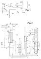
- the overall system of FIG. 1 has an air separation plant 100 and a glass production unit 200 in the strict sense.
- the air separation plant 100 is designed as a cryogenic air separation plant. It generates a nitrogen product 27, 110 and an oxygen product 120 from feed air 101. These are introduced at least partially as first gas mixture 112 or as second gas mixture 122 into the glass production unit 200, optionally mixed with a hydrogen stream 111 or an air stream 121.
- the glass production unit 200 has a burner 210 and a float glass trough 220.
- a molten glass 212 is produced from a glass raw material 211.
- the latter is then introduced into the float glass tray 220.
- the first gas mixture 112 is also passed; the introduction into the float glass trough 220 can be made at any suitable location, in particular contrary to the drawing from below.
- a fuel 213 is burned; the second gas mixture 122 supplies the oxygen for this purpose.
- Air separation plant shown in detail is used air (101 in FIG. 1 ) are compressed in one or more air compressors and then cleaned, in particular of water and carbon dioxide. (Air compression and air purification are in FIG. 2 not shown.)
- the first feed air stream 2 is cooled to about dew point, removed at the cold end of the main heat exchanger 4 and fed via line 5 without further pressure-changing measures the high-pressure column 6 of a distillation column system for nitrogen-oxygen separation, which also has a low-pressure column 7 and a main capacitor. 8 having.
- the operating pressures of the columns (in each case at the top) in the exemplary embodiment are 5.3 bar in the high-pressure column and 1.3 bar in the low-pressure column.
- the second feed air stream 3 is cooled in the main heat exchanger 4 only to an intermediate temperature and fed under this intermediate temperature via line 9 of an expansion turbine 10 and there to perform work to a pressure of 3.2 bar.
- the expanded second feed air stream 11 is fed to a mixing column 12 immediately above the sump.
- the operating pressure at the top of the mixing column 12 is 3.1 bar.
- the gaseous top nitrogen 13 of the high-pressure column 6 is introduced to a first part 14 in the main condenser 8 and there at least partially, preferably substantially completely condensed.
- generated in the main capacitor liquid nitrogen 15 15 is completely abandoned as reflux to the high-pressure column 6.
- the bottom liquid 20 of the high pressure column 6 is also cooled in the subcooling countercurrent 18 and introduced into the low pressure column 7, at an intermediate point.
- nitrogen 23 slightly below the impurity nitrogen 24 is withdrawn (alternatively, the conduit 24 is omitted). Both streams are heated in the supercooling countercurrent 18 and in the main heat exchanger 4 to about ambient temperature and as warm streams 23 and 25, respectively deducted. A portion, particularly of the warm impure nitrogen 25, may be reused within the air separation plant, for example as a regeneration gas for air purification and / or as a dry gas for the operation of an evaporative cooler which supplies cold water for pre-cooling the air (both not shown).
- a second part of the gaseous nitrogen head 13 of the high-pressure column 6 is warmed as a gaseous pressure nitrogen stream 26 in the main heat exchanger 4 to about ambient temperature and led out via line 27 from the air separation plant. At least a portion of it forms the nitrogen product (110 in FIG. 1 ) used to produce the first gas mixture 112 for the glass production unit 200 of the FIG. 1 is used (seal gas).
- Another part 28 may be used as additional pressurized nitrogen product (DGAN) for other purposes.
- the bottom liquid 30 of the low-pressure column 7 is brought liquid in an oxygen pump 31 to a pressure which is approximately above the mixing column pressure and overcomes the static height. At least a portion of the pumped liquid is introduced as a "liquid oxygen stream" via the lines 32, 33 and 34 with heating in the subcooling countercurrent 18 and in the cold part of the main heat exchanger 4 to the top of the mixing column 12. In direct countercurrent to the second feed air stream 11, it is vaporized in the mixing column 12.
- the bottom liquid 35, 36 of the mixing column 12 is introduced into the low-pressure column 7. Alternatively, the bottom liquid 35, 36 of the mixing column 12 could be cooled before being fed into the low pressure column 7 in the subcooling countercurrent 18.
- a gaseous oxygen stream 37 is removed, warmed in the main heat exchanger 4 to about ambient temperature, led out as oxygen product 120 (GOX) and finally for the preparation of the second gas mixture (122 in FIG. 1 ), either by being used directly as a second gas mixture or by being mixed with another stream 121.
- Another part 38 of the bottom liquid 30 of the low-pressure column 7 is removed continuously or intermittently as a rinsing liquid (LOX purge).
Landscapes
- Engineering & Computer Science (AREA)
- Physics & Mathematics (AREA)
- Mechanical Engineering (AREA)
- Thermal Sciences (AREA)
- General Engineering & Computer Science (AREA)
- Chemical & Material Sciences (AREA)
- Materials Engineering (AREA)
- Organic Chemistry (AREA)
- Combustion & Propulsion (AREA)
- Separation By Low-Temperature Treatments (AREA)
Abstract
Das Verfahren und die Vorrichtung dienen zur Erzeugung von Floatglas. Ein Glasrohstoff (211) wird mittels einem oder mehreren Brennern (210) geschmolzen. Die dabei gewonnene Glasschmelze (212) wird in eine Floatglaswanne (220) eingeleitet. Ein erstes Gasgemisch (112), das Stickstoff (110) und Wasserstoff (111) enthält, wird zur Bildung einer Inertschicht über der eingeleiteten Glasschmelze in die Floatglaswanne (220) eingeleitet. Der oder die Brenner (210) werden mit einem sauerstoffhaltigen Gas und einem Brennstoff (213) betrieben. Als sauerstoffhaltiges Gas wird ein zweites Gasgemisch (122) eingesetzt, das mindestens 35 % Sauerstoff enthält.
Description
- Als Floatglas wird Flachglas bezeichnet, das im Floatglasverfahren hergestellt wurde. Für das Schmelzen der Glasrohstoffe werden üblicherweise Brenner eingesetzt, die bisher mit Luft oder alternativ mit Sauerstoff beziehungsweise sauerstoffangereicherter Luft ("zweites Gasgemisch") betrieben werden. Das Schmelzen in Glasschmelzöfen mit Brennern, die den Brennstoff mit Sauerstoff anstelle von Luft verbrennen, hat vielfältige Vorteile wie zum Beispiel geringere Stickoxid-Emissionen, reduzierter Staubaustrag, niedrigerer Energieverbrauch, verbesserte Glasqualität und gesteigerte Schmelzleistung. Ein zusätzlicher Vorteil ist die wesentlich geringere Abgasmenge. Abgasreinigungsanlagen können daher kleiner sein und Luftvorwärmer entfallen, was zu niedrigeren Investitionskosten der Glasproduktionslinie führt.
- Es ist zudem bekannt, dass man bei der Herstellung von Floatglas in einer Floatglaswanne das geschmolzene Glas anschließend auf einem Bad aus geschmolzenem Zinn herstellt. Hierbei wird, um Verunreinigungen aus dem Metallbad zu entfernen, von unten ein Gemisch aus Stickstoff und Wasserstoff ("erstes Gasgemisch") eingeblasen, das anschließend auch den Raum über dem Bad inertisiert und somit das Zinnbad vor Oxydation und das Glas vor möglichen Verunreinigungen schützt.
- Der Erfindung liegt die Aufgabe zugrunde, ein Verfahren dieser Art und eine entsprechende Vorrichtung anzugeben, welche die Umwelt in besonders geringem Maße belasten.
- Diese Aufgabe wird durch die kennzeichnenden Merkmale des Anspruchs 1 gelöst.
- Bei den bisher bekannten Verfahren werden der Stickstoff für die Inertisierung und der Sauerstoff für die Brenner aus lokalen Speichern entnommen (beispielsweise Flüssigtanks), die von Zeit zu Zeit aus externen Quellen befüllt werden (beispielsweise mittels Tankfahrzeugen).
- Im Rahmen der Erfindung werden diese Stoffe jedoch vor Ort in einer Luftzerlegungsanlage erzeugt und mittels Rohrleitungen unmittelbar in die Glasproduktionsanlage im engeren Sinne eingeführt. "Vor Ort" bedeutet hier, dass die Entfernung zwischen Brennern und Floatglaswanne auf der einen Seite und Luftzerlegungsanlage auf der anderen Seite nicht mehr als 2.500 Meter beträgt und dass die Produkte der Luftzerlegungsanlage ausschließlich über Rohrleitungen zu der Floatglaswanne und dem zugehörigen Brenner transportiert werden. Trotz der hohen Kosten für eine Luftzerlegungsanlage vor Ort hat sich im Rahmen der Erfindung herausgestellt, dass das Verfahren dadurch insgesamt besonders kostengünstig und energiesparend und damit auch umweltfreundlich zu betrieben ist.
- Unter "Stickstoffprodukt" und "Sauerstoffprodukt" werden hier Produktströme der Luftzerlegungsanlage verstanden, welche die entsprechenden Luftkomponenten in höherer Konzentration als die Luft enthalten. Das Stickstoffprodukt einer Luftzerlegungsanlage enthält insbesondere mindestens 80 % Stickstoff, beispielsweise 90 bis 99 % Stickstoff. Beispielsweise enthält das Stickstoffprodukt noch Verunreinigungen von 0,5 ppm bis 2 % Sauerstoff und von Inertgasen wie Ar, He, Ne, H2-im Umfang von 1 bis 10 ppm. Das Sauerstoffprodukt enthält mindestens 40 % Sauerstoff, beispielsweise 80 bis 98 % Sauerstoff. Der Stickstoff wird zur Bildung des ersten Gasgemischs mit einer oder mehreren weiteren Komponenten vermischt, insbesondere mit Wasserstoff. Je nach Reinheit des Sauerstoffprodukts und nach genauer Betriebsweise der Brenner kann das Sauerstoffprodukt direkt als zweites Gasgemisch eingesetzt und insbesondere vor der Verbrennung mit dem Brennstoff vermischt werden; alternativ wird es zur Bildung des zweiten Gasgemischs mit Luft oder einem anderen geeigneten Gas verdünnt.
- Ein kleiner Teil des Stickstoffprodukts (etwa 100-200 Nm3/h) kann bei Bedarf permanent als Instrumentenluft für Instrumente im Floatprozess verwendet werden. Zudem wird mit einem anderen Teil des Stickstoffprodukts (etwa 300 bis 400 Nm3/h) ca. drei- bis fünfmal pro Jahr für drei bis vier Stunden eine Dachspülung durchgeführt. Diese kleineren Stickstoffmengen können aus einem zur Luftzerlegungsanlage gehörenden Notversorgungstank entnommen werden, da hierzu etwas erhöhte Drücke benötigt werden.
- Vorzugsweise liegt der Sauerstoffgehalt des sauerstoffangereicherten Gemischs zwischen 40 % und 99,8 %, insbesondere zwischen 80 und 97 %. (Diese und alle anderen Prozentangaben sind molar zu verstehen, sofern nichts anderes gesagt ist.)
- Es ist besonders vorteilhaft, wenn ist die Luftzerlegungsanlage durch eine Tieftemperatur-Luftzerlegungsanlage realisiert ist, in der Luft durch Destillation in Ihre Bestandteile getrennt wird.
- Besonders günstig ist eine Mischsäulenanlage nach Patentanspruch 5. Der Stickstoffstrom kann dabei am Kopf der Niederdrucksäule und/oder vom Kopf der Hochdrucksäule entnommen werden.
- Mischsäulen-Verfahren und -Vorrichtungen sind in
EP 697576 A1 EP 698772 A1 DE 19951521 A1 ,EP 1139046 A1 ,EP 1284404 A1 ,DE 10209421 A1 ,DE 10217093 A1 ,EP 1376037 A1 ,EP 1387136 A1 undEP 1666824 A1 beschrieben. - Besonders geeignet ist ein Prozess mit arbeitsleistender Entspannung der Mischsäulenluft, wie er an sich beispielsweise in
EP 697576 A1 EP 698772 A1 - Hierbei ist es besonders günstig, wenn der Betriebsdruck der Mischsäule zwischen 1,5 und 4,0 bar liegt, insbesondere zwischen 2,5 und 3,5 bar. Dieser Druck reicht im Allgemeinen für die Versorgung des oder der Brenner aus, sodass keine weiteren Maschinen und insbesondere keine Energie für die Verdichtung des Sauerstoffprodukts aufgewendet werden muss.
- Vorzugsweise wird der Stickstoff für das erste Gasgemisch aus der Hochdrucksäule abgezogen. Insbesondere in Verbindung mit einem oder mehreren oben genannten weiteren Parametern der Luftzerlegungsanlage ergibt sich damit ein höchst effiziente und damit umweltfreundliche Kombination aus Floatglasherstellung im engeren Sinne und Stickstoff- und Sauerstoffgewinnung vor Ort.
- Die Luftzerlegungsanlage wird vorzugsweise so ausgelegt, dass die benötigte Verfahrenskälte in einer einzigen Turbine erzeugt wird, die ausschließlich den zweiten Einsatzluftstrom (die Mischsäulenluft) arbeitsleistend entspannt. Diese Turbine allein deckt die Kältebilanz des Tieftemperatur-Prozesses. Dies erlaubt zusätzlich zur Sauerstoffgewinnung in der Mischsäule die Produktion von Druckstickstoff direkt aus der Hochdrucksäule ohne zusätzlichen Energieaufwand für die Verdichtung des Stickstoffs. Dieser weist einen Sauerstoffgehalt von 0,1 ppm bis 1000 ppm, typischerweise 1 bis 10 ppm und umfasst bis zu 25 % der Einsatzluftmenge.
- Ein Flachglaswerk kann mehrere Floatglaswannen aufweisen. Hierbei können einige oder alle Floatglaswannen aus derselben Luftzerlegungsanlage mit Stickstoff versorgt werden. Die Brenner mehrerer oder aller Floatglaswannen können mit Sauerstoff aus der Luftzerlegungsanlage betrieben werden, zum Beispiel mit Sauerstoff ohne Zumischung von Luft. Wenn die Stickstoffmenge ausreicht, ist es unter Umständen ist günstiger, einen oder mehrere Brenner mit einem Luft-Sauerstoffgemisch zu versorgen, anstatt eine größere Luftzerlegungsanlage zu verwenden.
- Typischerweise wird zur Erzeugung von Stickstoff eine spezifische Energie von 0,2 kWh/Nm3 benötigt. Diese Energie wird bei der Erfindung eingespart, da durch die gleichzeitige Verwendung von Sauerstoff und Stickstoff aus der Luftzerlegungsanlage der Energieaufwand für die Erzeugung von Stickstoff entfällt.
- Bei einem höheren Sauerstoffdruck von etwa 3,0 bar oder mehr reicht möglicherweise die in der Mischsäulenturbine erzeugte Kälte nicht aus. Dann kann alternativ oder zusätzlich ein Teil der Einsatzluft auf Niederdrucksäulendruck entspannt und direkt in die Niederdrucksäule eingeblasen werden. In diesem Fall kann weniger Druckstickstoff direkt der Hochdrucksäule entnommen werden. Der spezifische Energiebedarf für den entnommenen Stickstoff steigt dadurch auf ca. 0,1 KWh/Nm3, was aber immer noch ca. 50 % Einsparung gegenüber der Stickstofferzeugung ohne Nutzung des Sauerstoffs bedeutet. Alternativ könnte die durch die Druckstickstoffentnahme fehlende Kälte durch flüssigen Sauerstoff oder flüssigen Stickstoff aus einer externen Quelle kompensiert werden ("Liquid Assist").
- Die Erfindung betrifft außerdem eine Vorrichtung gemäß Patentanspruch 8. Die erfindungsgemäße Vorrichtung kann durch Vorrichtungsmerkmale ergänzt werden, die den Merkmalen der abhängigen Verfahrensansprüche entsprechen.
- Die Erfindung sowie weitere Einzelheiten der Erfindung werden im Folgenden anhand eines in den Zeichnungen schematisch dargestellten Ausführungsbeispiels näher erläutert. Hierbei zeigen:
-
Figur 1 ein Schema des Gesamtverfahrens und -
Figur 2 die konkrete Ausgestaltung des Luftzerlegungsverfahrens. - Das Gesamtsystem der
Figur 1 weist eine Luftzerlegungsanlage 100 und eine Glasproduktionseinheit 200 im engeren Sinne auf. - Die Luftzerlegungsanlage 100 ist als Tieftemperatur-Luftzerlegungsanlage ausgebildet. Sie erzeugt aus Einsatzluft 101 ein Stickstoffprodukt 27, 110 und ein Sauerstoffprodukt 120. Diese werden mindestens teilweise als erstes Gasgemisch 112 beziehungsweise als zweites Gasgemisch 122 in die Glasproduktionseinheit 200 eingeführt, gegebenenfalls vermischt mit einem Wasserstoffstrom 111 beziehungsweise einem Luftstrom 121.
- Die Glasproduktionseinheit 200 weist einen Brenner 210 und eine Floätglaswanne 220 auf. In dem Brenner wird aus einem Glasrohstoff 211 eine Glasschmelze 212 hergestellt. Letztere wird anschließend in die Floatglaswanne 220 eingeleitet. Dorthin wird auch das erste Gasgemisch 112 geleitet; die Einführung in die Floatglaswanne 220 kann an jeder geeigneten Stelle vorgenommen werden, insbesondere entgegen der zeichnerischen Darstellung von unten. In dem Brenner 210 wird ein Brennstoff 213 verbrannt; das zweite Gasgemisch 122 liefert dazu den Sauerstoff.
- In der in
Figur 2 im Detail dargestellten Luftzerlegungsanlage wird Einsatzluft (101 inFigur 1 ) in einem oder mehreren Luftverdichtern verdichtet und anschließend gereinigt, insbesondere von Wasser und Kohlendioxid. (Luftverdichtung und Luftreinigung sind inFigur 2 nicht dargestellt.) Die gereinigte Einsatzluft 1 steht unter einem Druck von 5,6 bar und wird in einen ersten Einsatzluftstrom (Direktluft) 2 und einen zweiten Einsatzluftstrom (Turbinenluft = Mischsäulenluft) 3 aufgeteilt, die beide einem Hauptwärmetauscher 4 am warmen Ende zugeleitet werden. Der erste Einsatzluftstrom 2 wird bis auf etwa Taupunkt abgekühlt, am kalten Ende dem Hauptwärmetauscher 4 entnommen und über Leitung 5 ohne weitere druckverändernde Maßnahmen der Hochdrucksäule 6 eines Destilliersäulen-Systems zur Stickstoff-Sauerstoff-Trennung zugeführt, das außerdem eine Niederdrucksäule 7 und einen Hauptkondensator 8 aufweist. Die Betriebsdrücke der Säulen (jeweils am Kopf) betragen in dem Ausführungsbeispiel 5,3 bar in der Hochdrucksäule und 1,3 bar in der Niederdrucksäule. - Der zweite Einsatzluftstrom 3 wird in dem Hauptwärmetauscher 4 nur auf eine Zwischentemperatur abgekühlt und unter dieser Zwischentemperatur über Leitung 9 einer Expansionsturbine 10 zugeführt und dort auf einen Druck von 3,2 bar arbeitsleistend entspannt. Der entspannte zweite Einsatzluftstrom 11 wird einer Mischsäule 12 unmittelbar oberhalb deren Sumpfs zugeleitet. Der Betriebsdruck am Kopf der Mischsäule 12 beträgt 3,1 bar.
- Der gasförmige Kopfstickstoff 13 der Hochdrucksäule 6 wird zu einem ersten Teil 14 in den Hauptkondensator 8 eingeleitet und dort mindestens teilweise, vorzugsweise im Wesentlichen vollständig kondensiert. Im Hauptkondensator 8 erzeugter flüssiger Stickstoff 15 wird in dem Ausführungsbeispiel vollständig als Rücklauf auf die Hochdrucksäule 6 aufgegeben. Einige praktische beziehungsweise theoretische Böden unterhalb des Kopfs der Hochdrucksäule 6 wird ein etwas weniger reiner Stickstoffstrom 17 flüssig entnommen, in einem Unterkühlungs-Gegenströmer 18 abgekühlt und über Leitung 19 als Rücklauf auf den Kopf der Niederdrucksäule 7 aufgegeben. Die Sumpfflüssigkeit 20 der Hochdrucksäule 6 wird ebenfalls im Unterkühlungs-Gegenströmer 18 abgekühlt und in die Niederdrucksäule 7 eingeleitet, und zwar an einer Zwischenstelle.
- Am Kopf der Niederdrucksäule 7 wird Stickstoff 23, etwas darunter Unreinstickstoff 24 abgezogen (alternativ wird die Leitung 24 weggelassen). Beide Ströme werden im Unterkühlungs-Gegenströmer 18 und im Hauptwärmetauscher 4 auf etwa Umgebungstemperatur angewärmt und als warme Ströme 23 beziehungsweise 25 abgezogen. Ein Teil, insbesondere des warmen Unreinstickstoffs 25, kann innerhalb der Luftzerlegungsanlage weiterverwendet werden, zum Beispiel als Regeneriergas für die Luftreinigung und/oder als trockenes Gas für den Betrieb eines Verdunstungskühlers, der kaltes Wasser für die Vorkühlung der Luft liefert (beides nicht dargestellt).
- Ein zweiter Teil des gasförmigen Kopfstickstoffs 13 der Hochdrucksäule 6 wird als gasförmiger Druckstickstoffstrom 26 im Hauptwärmetauscher 4 auf etwa Umgebungstemperatur angewärmt und über Leitung 27 aus der Luftzerlegungsanlage herausgeführt. Mindestens ein Teil davon bildet das Stickstoffprodukt (110 in
Figur 1 ), das zur Erzeugung des ersten Gasgemischs 112 für die Glasproduktionseinheit 200 derFigur 1 eingesetzt wird (Sealgas). Ein anderer Teil 28 kann als zusätzliches Druckstickstoffprodukt (DGAN) für andere Zwecke eingesetzt werden. - Die Sumpfflüssigkeit 30 der Niederdrucksäule 7 wird in einer Sauerstoffpumpe 31 flüssig auf einen Druck gebracht, der etwa über Mischsäulendruck liegt und die statische Höhe überwindet. Mindestens ein Teil der gepumpten Flüssigkeit wird als "flüssiger Sauerstoffstrom" über die Leitungen 32, 33 und 34 mit Anwärmung im Unterkühlungs-Gegenströmer 18 und im kalten Teil des Hauptwärmetauschers 4 auf den Kopf der Mischsäule 12 aufgegeben. Im direkten Gegenstrom zum zweiten Einsatzluftstrom 11 wird er in der Mischsäule 12 verdampft. Die Sumpfflüssigkeit 35, 36 der Mischsäule 12 wird in die Niederdrucksäule 7 eingeleitet. Alternativ könnte die Sumpfflüssigkeit 35, 36 der Mischsäule 12 vor der Einspeisung in die Niederdrucksäule 7 im Unterkühlungs-Gegenströmer 18 abgekühlt werden. Am Kopf der Mischsäule 12 wird ein gasförmiger Sauerstoffstrom 37 entnommen, im Hauptwärmetauscher 4 auf etwa Umgebungstemperatur angewärmt, als Sauerstoffprodukt 120 (GOX) herausgeführt und schließlich zur Herstellung des zweiten Gasgemischs (122 in
Figur 1 ) eingesetzt, entweder indem er unmittelbar als zweites Gasgemisch verwendet wird oder indem er mit einem anderen Strom 121 vermischt wird. - Ein anderer Teil 38 der Sumpfflüssigkeit 30 der Niederdrucksäule 7 wird kontinuierlich oder intermittierend als Spülflüssigkeit (LOX-Purge) entfernt.
Claims (8)
- Verfahren zur Erzeugung von Floatglas, bei dem Glasrohstoff (211) mittels einem oder mehreren Brennern (210) geschmolzen wird und die dabei gewonnene Glasschmelze (212) in eine Floatglaswanne (220) eingeleitet wird, wobei ein erstes Gasgemisch (112), das Stickstoff (110) und Wasserstoff (111) enthält, zur Bildung einer Inertschicht über der eingeleiteten Glasschmelze in die Floatglaswanne (220) eingeleitet wird, wobei der oder die Brenner (210) mit einem sauerstoffhaltigen Gas und einem Brennstoff (213) betrieben werden, wobei als sauerstoffhaltiges Gas ein zweites Gasgemisch (122) eingesetzt wird, das mindestens 35 % Sauerstoff enthält, dadurch gekennzeichnet, dass in einer Luftzerlegungsanlage (100) vor Ort mindestens ein Sauerstoffprodukt (120) und mindestens ein Stickstoffprodukt (110) hergestellt werden, wobei das Stickstoffprodukt (110) zur Herstellung des ersten Gasgemischs (112) und das Sauerstoffprodukt (120) zur Herstellung des zweiten Gasgemischs (122) eingesetzt werden.
- Verfahren nach Anspruch 1, dadurch gekennzeichnet, dass der Sauerstoffgehalt des zweiten Gasgemischs (122) zwischen 40 % und 99,8 %, insbesondere zwischen 80 und 97 % liegt.
- Verfahren nach Anspruch 1 oder 2, dadurch gekennzeichnet, dass die Luftzerlegungsanlage (100) als Tieftemperatur-Luftzerlegungsanlage ausgebildet ist.
- Verfahren nach Anspruch 3, dadurch gekennzeichnet, dass die Tieftemperatur-Luftzerlegungsanlage (100) ein Destilliersäulen-System zur Stickstoff-Sauerstoff-Trennung und eine Mischsäule (12) aufweist, wobei- das Destilliersäulen-System zur Stickstoff-Sauerstoff-Trennung eine Hochdrucksäule (6) und eine Niederdrucksäule (7) aufweist,- ein erster Einsatzluftstrom (2, 5) in die Hochdrucksäule (6) eingeleitet wird,- ein flüssiger Sauerstoffstrom (30, 32, 33, 34) aus der Niederdrucksäule (7) in den oberen Bereich der Mischsäule (12) eingeleitet wird,- ein zweiter Einsatzluftstrom (3, 9, 11) gasförmig in den unteren Bereich der Mischsäule (12) eingeleitet wird,- ein gasförmiger Sauerstoffstrom (37) aus dem oberen Bereich der Mischsäule (12) entnommen und mindestens zum Teil als Sauerstoffprodukt (120) herausgeführt und zur Herstellung des zweiten Gasgemischs (122) eingesetzt wird und- ein Stickstoffstrom (26,27) aus dem Destilliersäulen-System zur Stickstoff-Sauerstoff-Trennung abgezogen und mindestens zum Teil als Stickstoffprodukt (110) herausgeführt und zur Herstellung des ersten Gasgemischs (112) eingesetzt wird.
- Verfahren nach Anspruch 4, dadurch gekennzeichnet, dass der zweite Einsatzluftstrom (3, 9) vor seiner Einleitung in die Mischsäule (12) arbeitsleistend entspannt (10) wird.
- Verfahren nach Anspruch 4 oder 5, dadurch gekennzeichnet, dass der Betriebsdruck der Mischsäule (12) zwischen 1,5 und 3,5 bar liegt, insbesondere zwischen 2,5 und 3,2 bar.
- Verfahren nach einem der Ansprüche 4 bis 6, dadurch gekennzeichnet, dass ein gasförmiger Druckstickstoffstrom (13) aus der Hochdrucksäule (6) abgezogen und mindestens zum Teil (26, 27) als Stickstoffprodukt (110) herausgeführt und zur Herstellung des ersten Gasgemischs (112) eingesetzt wird.
- Vorrichtung zur Erzeugung von Floatglas mit einem oder mehreren Brennern (210) zum Schmelzen von Glasrohstoff (211), mit Mitteln zum Einleiten der dabei gewonnenen Glasschmelze (212) in eine Floatglaswanne (220), mit Mitteln zum Einleiten eines erstes Gasgemisch (112), das Stickstoff (110) und Wasserstoff (111) enthält, zur Bildung einer Inertschicht über der eingeleiteten Glasschmelze in die Floatglaswanne (220) und mit Mitteln zum Einleiten eines sauerstoffhaltigen Gases und einem Brennstoffs (213) in den oder die Brenner (210), wobei die Mittel zum Einleiten eines sauerstoffhaltigen Gases in den oder die Brenner (210) mit einer Quelle für ein zweites Gasgemisch (122) verbunden sind, das mindestens 35 % Sauerstoff enthält, gekennzeichnet durch eine Luftzerlegungsanlage (100) vor Ort zur Herstellung mindestens eines Sauerstoffprodukts (120) und mindestens eines Stickstoffprodukts (110), durch Mittel zur Bildung des ersten Gasgemischs (112) unter Verwendung des Stickstoffprodukts (110) und durch Mittel zur Bildung des zweiten Gasgemischs (122) unter Verwendung des Sauerstoffprodukts (120).
Applications Claiming Priority (1)
| Application Number | Priority Date | Filing Date | Title |
|---|---|---|---|
| DE102011015430A DE102011015430A1 (de) | 2011-03-29 | 2011-03-29 | Verfahren und Vorrichtung zur Erzeugung von Flachgas |
Publications (1)
| Publication Number | Publication Date |
|---|---|
| EP2505947A1 true EP2505947A1 (de) | 2012-10-03 |
Family
ID=44117179
Family Applications (1)
| Application Number | Title | Priority Date | Filing Date |
|---|---|---|---|
| EP11004356A Withdrawn EP2505947A1 (de) | 2011-03-29 | 2011-05-26 | Verfahren und Vorrichtung zur Erzeugung von Floatglas |
Country Status (2)
| Country | Link |
|---|---|
| EP (1) | EP2505947A1 (de) |
| DE (1) | DE102011015430A1 (de) |
Cited By (1)
| Publication number | Priority date | Publication date | Assignee | Title |
|---|---|---|---|---|
| CN113336423A (zh) * | 2021-05-11 | 2021-09-03 | 中建材佳星玻璃(黑龙江)有限公司 | 一种无氢站浮法玻璃生产工艺 |
Citations (12)
| Publication number | Priority date | Publication date | Assignee | Title |
|---|---|---|---|---|
| EP0697576A1 (de) | 1994-08-17 | 1996-02-21 | The Boc Group, Inc. | Verfahren und Vorrichtung zur Lufttrennung |
| EP0698772A1 (de) | 1994-08-25 | 1996-02-28 | The Boc Group, Inc. | Verfahren und Vorrichtung zur Herstellung von Sauerstoff |
| US5888265A (en) * | 1997-12-22 | 1999-03-30 | Praxair Technology, Inc. | Air separation float glass system |
| DE19951521A1 (de) | 1999-10-26 | 2001-05-03 | Linde Ag | Verfahren und Vorrichtung zur Gewinnung eines Druckprodukts durch Tieftemperaturzerlegung von Luft |
| EP1139046A1 (de) | 2000-03-29 | 2001-10-04 | Linde Aktiengesellschaft | Verfahren und Vorrichtung zur Gewinnung eines Druckprodukts durch Tieftemperaturzerlegung von Luft |
| US20030010061A1 (en) * | 2001-06-28 | 2003-01-16 | Bao Ha | Methods and apparatuses related to the integration of an air separation unit and a glass facility |
| DE10217093A1 (de) | 2002-04-17 | 2003-01-23 | Linde Ag | Verfahren zur Regelung eines Trennsäulen-Systems zur Gaszerlegung |
| EP1284404A1 (de) | 2001-08-13 | 2003-02-19 | Linde Aktiengesellschaft | Verfahren und Vorrichtung zur Gewinnung eines Druckprodukts durch Tieftemperaturzerlegung von Luft |
| DE10209421A1 (de) | 2002-03-05 | 2003-04-03 | Linde Ag | Verfahren und Vorrichtung zur Gewinnung eines Druckprodukts durch Tieftemperaturzerlegung von Luft |
| EP1376037A1 (de) | 2002-06-24 | 2004-01-02 | Linde Aktiengesellschaft | Luftzerlegungsverfahren und -anlage mit Mischsäule und Krypton-Xenon-Gewinnung |
| EP1387136A1 (de) | 2002-08-02 | 2004-02-04 | Linde AG | Verfahren und Vorrichtung zur Erzeugung von unreinem Sauerstoff durch Tieftemperaturzerlegung von Luft |
| EP1666824A1 (de) | 2004-12-03 | 2006-06-07 | Linde Aktiengesellschaft | Verfahren und Vorrichtung zur Gewinnung von Argon durch Tieftemperaturzerlegung von Luft |
-
2011
- 2011-03-29 DE DE102011015430A patent/DE102011015430A1/de not_active Withdrawn
- 2011-05-26 EP EP11004356A patent/EP2505947A1/de not_active Withdrawn
Patent Citations (12)
| Publication number | Priority date | Publication date | Assignee | Title |
|---|---|---|---|---|
| EP0697576A1 (de) | 1994-08-17 | 1996-02-21 | The Boc Group, Inc. | Verfahren und Vorrichtung zur Lufttrennung |
| EP0698772A1 (de) | 1994-08-25 | 1996-02-28 | The Boc Group, Inc. | Verfahren und Vorrichtung zur Herstellung von Sauerstoff |
| US5888265A (en) * | 1997-12-22 | 1999-03-30 | Praxair Technology, Inc. | Air separation float glass system |
| DE19951521A1 (de) | 1999-10-26 | 2001-05-03 | Linde Ag | Verfahren und Vorrichtung zur Gewinnung eines Druckprodukts durch Tieftemperaturzerlegung von Luft |
| EP1139046A1 (de) | 2000-03-29 | 2001-10-04 | Linde Aktiengesellschaft | Verfahren und Vorrichtung zur Gewinnung eines Druckprodukts durch Tieftemperaturzerlegung von Luft |
| US20030010061A1 (en) * | 2001-06-28 | 2003-01-16 | Bao Ha | Methods and apparatuses related to the integration of an air separation unit and a glass facility |
| EP1284404A1 (de) | 2001-08-13 | 2003-02-19 | Linde Aktiengesellschaft | Verfahren und Vorrichtung zur Gewinnung eines Druckprodukts durch Tieftemperaturzerlegung von Luft |
| DE10209421A1 (de) | 2002-03-05 | 2003-04-03 | Linde Ag | Verfahren und Vorrichtung zur Gewinnung eines Druckprodukts durch Tieftemperaturzerlegung von Luft |
| DE10217093A1 (de) | 2002-04-17 | 2003-01-23 | Linde Ag | Verfahren zur Regelung eines Trennsäulen-Systems zur Gaszerlegung |
| EP1376037A1 (de) | 2002-06-24 | 2004-01-02 | Linde Aktiengesellschaft | Luftzerlegungsverfahren und -anlage mit Mischsäule und Krypton-Xenon-Gewinnung |
| EP1387136A1 (de) | 2002-08-02 | 2004-02-04 | Linde AG | Verfahren und Vorrichtung zur Erzeugung von unreinem Sauerstoff durch Tieftemperaturzerlegung von Luft |
| EP1666824A1 (de) | 2004-12-03 | 2006-06-07 | Linde Aktiengesellschaft | Verfahren und Vorrichtung zur Gewinnung von Argon durch Tieftemperaturzerlegung von Luft |
Cited By (1)
| Publication number | Priority date | Publication date | Assignee | Title |
|---|---|---|---|---|
| CN113336423A (zh) * | 2021-05-11 | 2021-09-03 | 中建材佳星玻璃(黑龙江)有限公司 | 一种无氢站浮法玻璃生产工艺 |
Also Published As
| Publication number | Publication date |
|---|---|
| DE102011015430A1 (de) | 2012-10-04 |
Similar Documents
| Publication | Publication Date | Title |
|---|---|---|
| EP1067345B1 (de) | Verfahren und Vorrichtung zur Tieftemperaturzerlegung von Luft | |
| DE69214409T3 (de) | Verfahren zur Herstellung unreinen Sauerstoffs | |
| DE10139727A1 (de) | Verfahren und Vorrichtung zur Gewinnung eines Druckprodukts durch Tieftemperaturzerlegung von Luft | |
| DE3840506A1 (de) | Verfahren und vorrichtung zur luftzerlegung | |
| EP0955509A1 (de) | Verfahren und Vorrichtung zur Gewinnung von hochreinem Sauerstoff | |
| EP1666824A1 (de) | Verfahren und Vorrichtung zur Gewinnung von Argon durch Tieftemperaturzerlegung von Luft | |
| DE10228111A1 (de) | Luftzerlegungsverfahren und -anlage mit Mischsäule und Krypton-Xenon-Gewinnung | |
| EP2313724A2 (de) | Verfahren und vorrichtung zur tieftemperaturzerlegung von luft | |
| DE10334560A1 (de) | Verfahren und Vorrichtung zur Gewinnung von Krypton und/oder Xenon durch Tieftemperaturzerlegung von Luft | |
| EP3207320A1 (de) | Verfahren und vorrichtung zur variablen gewinnung von argon durch tieftemperaturzerlegung | |
| DE69007032T2 (de) | Verfahren und Einrichtung zur Luftdestillierung mit Argongewinnung. | |
| EP0171711A2 (de) | Verfahren und Vorrichtung zur Zerlegung von Rohargon | |
| DE102017010786A1 (de) | Verfahren und Vorrichtung zur Gewinnung eines Hochreinsauerstoffproduktstroms durch Tieftemperaturzerlegung von Luft | |
| DE19951521A1 (de) | Verfahren und Vorrichtung zur Gewinnung eines Druckprodukts durch Tieftemperaturzerlegung von Luft | |
| EP2938952A2 (de) | Verfahren und vorrichtung zur tieftemperatur-luftzerlegung | |
| DE3107151A1 (de) | Verfahren und vorrichtung zur verfluessigung und zerlegung von luft | |
| DE19855485A1 (de) | Verfahren und Vorrichtung zur Gewinnung eines krypton- und/oder xenonangereicherten Gemischs durch Gegenstrom-Stoffaustausch | |
| EP1300640A1 (de) | Verfahren und Vorrichtung zur Gewinnung von hoch reinem Stickstoff durch Tieftemperaturzerlegung von Luft | |
| DE202009004099U1 (de) | Vorrichtung zur Tieftemperaturzerlegung von Luft | |
| DE102011015430A1 (de) | Verfahren und Vorrichtung zur Erzeugung von Flachgas | |
| EP2906889A2 (de) | Verfahren und anlage zur erzeugung flüssiger und gasförmiger sauerstoffprodukte durch tieftemperaturzerlegung von luft | |
| EP3870917B1 (de) | Verfahren und anlage zur tieftemperaturzerlegung von luft | |
| DE60020500T2 (de) | Verfahren zur Luftzerlegung durch Tieftemperaturdestillation | |
| WO2023083488A1 (de) | Verfahren und anordnung zur erzeugung eines argonprodukts und eines sauerstoffprodukts und verfahren zum umrüsten einer oder mehrerer luftzerlegungsanlagen | |
| DE3035844A1 (de) | Verfahren und vorrichtung zur gewinnung von sauerstoff mittlerer reinheit |
Legal Events
| Date | Code | Title | Description |
|---|---|---|---|
| PUAI | Public reference made under article 153(3) epc to a published international application that has entered the european phase |
Free format text: ORIGINAL CODE: 0009012 |
|
| AK | Designated contracting states |
Kind code of ref document: A1 Designated state(s): AL AT BE BG CH CY CZ DE DK EE ES FI FR GB GR HR HU IE IS IT LI LT LU LV MC MK MT NL NO PL PT RO RS SE SI SK SM TR |
|
| AX | Request for extension of the european patent |
Extension state: BA ME |
|
| STAA | Information on the status of an ep patent application or granted ep patent |
Free format text: STATUS: THE APPLICATION IS DEEMED TO BE WITHDRAWN |
|
| 18D | Application deemed to be withdrawn |
Effective date: 20130404 |