EP2505850A2 - Lagerbuchse - Google Patents
Lagerbuchse Download PDFInfo
- Publication number
- EP2505850A2 EP2505850A2 EP20120000540 EP12000540A EP2505850A2 EP 2505850 A2 EP2505850 A2 EP 2505850A2 EP 20120000540 EP20120000540 EP 20120000540 EP 12000540 A EP12000540 A EP 12000540A EP 2505850 A2 EP2505850 A2 EP 2505850A2
- Authority
- EP
- European Patent Office
- Prior art keywords
- bearing
- wall
- bearing bush
- bush
- sector
- Prior art date
- Legal status (The legal status is an assumption and is not a legal conclusion. Google has not performed a legal analysis and makes no representation as to the accuracy of the status listed.)
- Granted
Links
Images

Classifications
-
- F—MECHANICAL ENGINEERING; LIGHTING; HEATING; WEAPONS; BLASTING
- F04—POSITIVE - DISPLACEMENT MACHINES FOR LIQUIDS; PUMPS FOR LIQUIDS OR ELASTIC FLUIDS
- F04D—NON-POSITIVE-DISPLACEMENT PUMPS
- F04D29/00—Details, component parts, or accessories
- F04D29/04—Shafts or bearings, or assemblies thereof
- F04D29/046—Bearings
- F04D29/0462—Bearing cartridges
-
- F—MECHANICAL ENGINEERING; LIGHTING; HEATING; WEAPONS; BLASTING
- F04—POSITIVE - DISPLACEMENT MACHINES FOR LIQUIDS; PUMPS FOR LIQUIDS OR ELASTIC FLUIDS
- F04D—NON-POSITIVE-DISPLACEMENT PUMPS
- F04D29/00—Details, component parts, or accessories
- F04D29/04—Shafts or bearings, or assemblies thereof
- F04D29/046—Bearings
-
- F—MECHANICAL ENGINEERING; LIGHTING; HEATING; WEAPONS; BLASTING
- F04—POSITIVE - DISPLACEMENT MACHINES FOR LIQUIDS; PUMPS FOR LIQUIDS OR ELASTIC FLUIDS
- F04D—NON-POSITIVE-DISPLACEMENT PUMPS
- F04D29/00—Details, component parts, or accessories
- F04D29/60—Mounting; Assembling; Disassembling
- F04D29/62—Mounting; Assembling; Disassembling of radial or helico-centrifugal pumps
- F04D29/628—Mounting; Assembling; Disassembling of radial or helico-centrifugal pumps especially adapted for liquid pumps
-
- F—MECHANICAL ENGINEERING; LIGHTING; HEATING; WEAPONS; BLASTING
- F16—ENGINEERING ELEMENTS AND UNITS; GENERAL MEASURES FOR PRODUCING AND MAINTAINING EFFECTIVE FUNCTIONING OF MACHINES OR INSTALLATIONS; THERMAL INSULATION IN GENERAL
- F16C—SHAFTS; FLEXIBLE SHAFTS; ELEMENTS OR CRANKSHAFT MECHANISMS; ROTARY BODIES OTHER THAN GEARING ELEMENTS; BEARINGS
- F16C27/00—Elastic or yielding bearings or bearing supports, for exclusively rotary movement
- F16C27/02—Sliding-contact bearings
-
- F—MECHANICAL ENGINEERING; LIGHTING; HEATING; WEAPONS; BLASTING
- F16—ENGINEERING ELEMENTS AND UNITS; GENERAL MEASURES FOR PRODUCING AND MAINTAINING EFFECTIVE FUNCTIONING OF MACHINES OR INSTALLATIONS; THERMAL INSULATION IN GENERAL
- F16C—SHAFTS; FLEXIBLE SHAFTS; ELEMENTS OR CRANKSHAFT MECHANISMS; ROTARY BODIES OTHER THAN GEARING ELEMENTS; BEARINGS
- F16C35/00—Rigid support of bearing units; Housings, e.g. caps, covers
- F16C35/02—Rigid support of bearing units; Housings, e.g. caps, covers in the case of sliding-contact bearings
-
- H—ELECTRICITY
- H02—GENERATION; CONVERSION OR DISTRIBUTION OF ELECTRIC POWER
- H02K—DYNAMO-ELECTRIC MACHINES
- H02K5/00—Casings; Enclosures; Supports
- H02K5/04—Casings or enclosures characterised by the shape, form or construction thereof
- H02K5/16—Means for supporting bearings, e.g. insulating supports or means for fitting bearings in the bearing-shields
- H02K5/167—Means for supporting bearings, e.g. insulating supports or means for fitting bearings in the bearing-shields using sliding-contact or spherical cap bearings
- H02K5/1672—Means for supporting bearings, e.g. insulating supports or means for fitting bearings in the bearing-shields using sliding-contact or spherical cap bearings radially supporting the rotary shaft at both ends of the rotor
-
- F—MECHANICAL ENGINEERING; LIGHTING; HEATING; WEAPONS; BLASTING
- F16—ENGINEERING ELEMENTS AND UNITS; GENERAL MEASURES FOR PRODUCING AND MAINTAINING EFFECTIVE FUNCTIONING OF MACHINES OR INSTALLATIONS; THERMAL INSULATION IN GENERAL
- F16C—SHAFTS; FLEXIBLE SHAFTS; ELEMENTS OR CRANKSHAFT MECHANISMS; ROTARY BODIES OTHER THAN GEARING ELEMENTS; BEARINGS
- F16C2360/00—Engines or pumps
- F16C2360/44—Centrifugal pumps
-
- F—MECHANICAL ENGINEERING; LIGHTING; HEATING; WEAPONS; BLASTING
- F16—ENGINEERING ELEMENTS AND UNITS; GENERAL MEASURES FOR PRODUCING AND MAINTAINING EFFECTIVE FUNCTIONING OF MACHINES OR INSTALLATIONS; THERMAL INSULATION IN GENERAL
- F16C—SHAFTS; FLEXIBLE SHAFTS; ELEMENTS OR CRANKSHAFT MECHANISMS; ROTARY BODIES OTHER THAN GEARING ELEMENTS; BEARINGS
- F16C2380/00—Electrical apparatus
- F16C2380/26—Dynamo-electric machines or combinations therewith, e.g. electro-motors and generators
Definitions
- the present invention relates to a bearing bush for receiving a bearing for a rotor of an electric machine, in particular an electric motor driven centrifugal pump, with a substantially cylindrical wall made of plastic, which surrounds the bearing in its inserted state.
- Bushings are used for mounting bearings, through which a rotatable shaft is guided. Such arrangements are particularly important in rotors of electric motors and generators whose shaft is mounted in two places in the rotor chamber.
- electric motor driven centrifugal pumps with wet running rotor bearings and the corresponding bushings are washed by the pumped medium.
- Wet-runner pumps have a gap tube or a containment shell for hermetically separating the rotor space from the stator, in which a bearing bush is inserted and held in a rotationally fixed manner.
- split pans having integral means for mounting bearings at their bottom side are known.
- EP 1024 584 A2 a containment shell for a centrifugal pump, in which two bearings are arranged for mounting the motor shaft, wherein at least the arranged at the bottom of the gap pot bearing is axially, radially and rotationally fixed positively held in the containment shell.
- the bottom of the split pot is spherical and has a bearing seat for receiving a radial sliding bearing.
- the bearing seat has four latching arms which extend axially tapering in the direction of the pump.
- the locking arms are integral to the ground molded and can resiliently spring outward. At their free ends they each have an inwardly projecting projection. Each projection engages in a recess of the bearing, which are formed on the outside of the bearing. Between the locking arms rigid centering elements are arranged, held radially positively by the bearing and is centered.
- a bearing bush of the type mentioned in the introductory part It describes a containment shell of an electrically driven pump, at the bottom of a bushing is provided for a bearing.
- This bushing is formed by a substantially cylindrical, circular cross-section wall, which is a part of the bottom end of the splitrope.
- the wall has on its directed into the rotor chamber end face a shoulder from which an annular collar projects axially.
- a bearing is used, which protrudes axially over the shoulder and over the collar and having a recess at the level of the shoulder.
- a shoulder is also formed on the bearing, so that on this shoulder and the opposite shoulder of the seat, that is, between the bearing and the collar an O-ring, which radially fixes the bearing.
- the collar is encompassed by an annular retaining element, the front side covers the bearing and axially fixed.
- EP 2 017479 A2 is a split shell made of plastic, which separates the rotor from the stator in the electric motor and is flowed through by the liquid to be pumped.
- the containment shell forms a coaxial pipe section of smaller diameter than the remaining containment shell.
- this pipe section is a radial bearing as Kohlegleitlager coaxial and takes the rear end of the engine or pump shaft, not shown.
- An annular fixing element of ethylene-propylene-diene rubber (EPDM) is seated coaxially on the outer jacket of the radial bearing in a region facing the pump rotor, the fastening of the fixing element on the radial bearing being positive and / or non-positive.
- a release of the press bond between the bearing and bearing bush takes place, so that a game between the bearing and bushing arises.
- the object of the present invention is to provide a bushing for mounting a bearing within a Spaltrohes or split pot, which is simple and inexpensive to manufacture, allows easy mounting of the bearing or itself can be easily mounted, and a permanent radial and axial seat of the Warehouse without additional fasteners are required.
- a bearing bush for receiving a cylindrical bearing for a rotor of an electric machine, in particular an electric motor driven centrifugal pump proposed, having a substantially cylindrical wall of plastic, which surrounds the bearing in its inserted state, wherein the wall has sector portions whose radial inner sides form contact surfaces, between which the bearing is non-positively durable, and the Wall between the sector sections has radially outwardly directed bulges.
- the basic idea of the present invention is to select the geometric shape of a bearing bush in such a way that the forces and stresses acting in it are evenly distributed over the entire service temperature and operating pressure range and the bearing bush can deform elastically without damage as a function of these stresses and forces in case of expansion as well as contraction.
- the sector sections are those peripheral sections of the wall on which a bearing in the bearing bush only partially rests on the wall. It is due to the inner contact surfaces of the bearing bush, which hold the bearing non-positively and radially fix. As a result, no further means for holding the camp are needed.
- the abutment surfaces can be comparatively wide in the circumferential direction of the wall, but alternatively can also be designed to be very narrow, so that a bearing comes only minimally partially in contact with the bushing.
- the sector sections there is a press fit between the bearing and bush, while the wall in the region of the bulges extends at a distance from the bearing. This causes the forces absorbed by the sector sections to be diverted into these wall areas between them, so that the wall can easily deform elastically there due to the lack of contact with the bearing.
- the contact surfaces cause a centering of the bearing in the bearing bush, so that it can come to rest exactly coaxial in the socket.
- the lobes cause medium to flow through the lobes behind the bearing in medium-purged bearings, such as those found in wet-rotor motors for pumps. As a result, a strong heat dissipation is achieved and prevents dirt particles settle in the otherwise existing between bearing and bushing gap, which lead to increased friction and thereby increased closure
- the wall is at least partially closed in the circumferential direction. This means that the sector sections and the areas between them merge and the wall is not interrupted at any point along its entire axial extent. This has the advantage that the stresses and forces are evenly distributed over the entire circumference of the wall. It can thereby be avoided that breaks occur at locations that are subjected to higher force than other locations of the wall.
- the bulges are formed by arc sections of the wall. This causes the radial forces picked up by the sector sections to pass into the sections between them, i. the arc sections, diverted and distributed in the circumferential direction.
- the arc sections in this case immediately adjoin the sector sections. They connect the mutually facing end sides of two adjacent sector sections arcuately.
- the arcuate portions may be part-circular cylinder-shaped so as to interconnect the mutually facing end sides of two adjacent sector portions in the form of a part of a circular cylinder.
- the radius of curvature of the arcuate portions is smaller than the distance of a contact surface to the bearing bush axis, so that the bulges have a radius which is smaller than the radius defined by the contact surfaces to the bearing bush axis. Since the mutually facing end sides of two adjacent sector sections are connected by the arc sections, the end sides lie on the circular cylinder, so that the smaller radius of curvature results in the radial bulges, which are concave shaped from the perspective of the bearing bush axis.
- the radius of curvature can be between four and six tenths of the distance between the contact surface and the bearing bush axis.
- the wall may be wavy in the circumferential direction. This means that the wall runs in the circumferential direction alternately radially inwards and radially outwards.
- the contact surfaces are comparatively narrow in this case by the inner sides the wave troughs formed. The waveform leads to stress homogeneity within the wall.
- the wall can have a plurality of bulges, in particular three, four, five or more such bulges, which are distributed at equal angular distances from one another.
- the shape of the wall may be epicycloidic, i. describe an epicycloid in cross-section.
- the thickness of the wall of the sector sections may be at least partially greater than the thickness of the wall between the sector sections. This will be stable and it is an overuse of the sector sections prevented because they form the press connection with the bearing.
- the bearing bush has a bottom.
- the wall extends away from the floor in the axial direction and the bearing bush is closed on at least one side, the bottom side.
- the wall may be integrally formed with the ground.
- the geometric shape of the bearing bush is thereby fixed to an axial end and limited in terms of their elasticity.
- the bearing bush has at least one spacer on which the bearing rests in the inserted state.
- the spacer may project peg-shaped from the ground.
- the spacer forms on the one hand a stop for the bearing in the axial direction and can thus serve to absorb axial forces which are absorbed by the bearing.
- On the other hand causes the spacer that the bearing is not applied to the ground.
- two, three or more spacers may be provided. These can be formed the same shape. Furthermore, the spacers may be arranged symmetrically to each other, in particular at equal angular intervals on the ground.
- the sector sections may be extended in their axial extension direction relative to the wall in the region of the bulges and may have latching lugs for overlapping an inserted bearing at their open ends. In this way, the bearing between the locking lugs and the spacers can be fixed axially.
- At least the contact surfaces of the sector sections of the wall can be slightly inclined in the axial direction to the bearing bush axis. This causes a uniform distribution of the mechanical stress along much of the axial length of the bearing bush.
- the inclination can run at an angle between 0.05 ° and 5 °, preferably between 0.5 ° and 2 ° to the bearing bush axis.
- the contact surfaces can be concave.
- a press fit between these parts can be used.
- the distance between the contact surfaces to the bearing bush axis 0.5 mm to 1 mm smaller than the outer radius of the bearing.
- the wall has at least one projection on its inner side facing the bearing bush axis, which can engage positively in a recess of the bearing in its inserted state.
- This positive locking fixes the bearing in the circumferential direction and prevents a rotational relative movement between the bearing and the bearing bush.
- the projection may have on the wall the shape of a rib which extends at least partially along the axial length of the wall. Alternatively or cumulatively at least protrude a projection from the ground in the axial direction and engage in a corresponding recess on the bearing.
- the projection may be integrally formed on a pedestal-shaped spacer.
- a can for wet-rotor motors which has at least one axial end of a bearing bush according to one of the preceding claims.
- the bearing bush can be inserted non-positively in this case at the one end or form part of the splitroot.
- the bearing bush and the containment shell are integrally formed and structurally form a unit that can be injected or molded in a plastic manufacturing step.
- the bottom of the bearing bush at the same time forms at least a part of the bottom of the can.
- the canned pipe in this case represents a containment shell.
- the wall of the bearing bush protrudes in the axial direction from the bottom of the can or split pot, so that the wall of the bearing bush is almost complete, except for the abutment surfaces. both outside and radially inside the sleeve medium flows around. In this case, no pressure acts on the wall, which in this case lies completely inside the split tube or containment shell, so that there is no additional mechanical stress.
- the wall of the bearing bush can form part of the wall of the can. This means that the split tube itself has the bulges, in particular the wave-shaped in the circumferential direction cross-section.
- FIG. 1 shows a bearing bush 1 according to the invention for receiving a cylindrical radial bearing 2 for a rotor, not shown, a wet-rotor motor, in particular an electric motor driven centrifugal pump in a radial cross-section.
- the bushing is made of a thermoplastic or thermosetting plastic, and has a cylindrical, circumferentially closed wall 3, which surrounds the bearing 2 in its inserted state, see FIG. 2 ,
- the wall 3 has five sector sections 4, whose radially inner sides form contact surfaces 5, on which the bearing 2 partially comes into contact and between which the bearing 2 is non-positively durable or is held in the inserted state. Due to the symmetrical arrangement of the five sector sections 4 at equal angular intervals of 72 ° each, the bearing 2 is centered within the bushing and radially fixed.
- the sector sections 4 form a segmented interference fit over the circumference of the bearing 2.
- the contact surfaces 5 extend over a minimum width that can be generated in the injection molding tool, the system diameter defining an interference fit together with the outer diameter of the bearing 2.
- the segmented attachment of the radial bearing 2 in the bearing bush 1 by means of a press fit has the advantage that individual segments can be adapted in the injection molding tool. This eventually leads to a best possible centric seat of the bearing. 2
- the wall 3 has five radially outwardly directed bulges 6, which are formed by arc sections 7 of the wall 3, which are partially circular cylindrical in this embodiment.
- the invention is not limited to part-circular cylindrical arc sections.
- the geometric structure of the bearing bush 1 according to the invention can deform. This results in a press connection over the entire area of application of the bearing bush 1.
- the geometry of the bushing 1 is characterized stress and strain optimized.
- the areas 7 between the partial contact surfaces 5 are designed such that, due to the pressed-in bearing 2 sets a state of similar stresses around the circumference of the bushing 1. With such a geometry, sufficiently large oversizes between the mating partners can be realized without exceeding the permissible material limit values specified by the materials and / or eliminating the bond between the bearing bush and the bearing.
- the radius of curvature of the arcuate portions 7 is smaller than the distance of a contact surface 5 to the bearing bush axis 8, so that the bulges 6 have a radius r a , which is smaller than the defined by the contact surfaces 5 to the bearing bush axis 8 radius r i .
- the wall 3 surrounds three spacers 10, which are at equal angular intervals of 120 ° from the in FIG. 1 raise bottom 9 not shown. They form axial stops for the bearing 2. Furthermore, the wall 3 itself is surrounded by a further wall, which is part of a split tube 12, with which the bearing bush 1 is integrally formed.
- FIG. 2 shows the bearing bush 1 in the radial cross section with inserted bearing 2.
- the bulges 6 are formed by the free spaces between the arcuate portions 7 and the bearing 2. They serve to ensure that the liquid contained in the can flow past the bulges 6 on the bearing 2 and flood the rear area of the bearing bush 1, so that on the one hand cooling of the bearing takes place, on the other hand good lubrication of the bearing and additionally in the liquid Contaminated dirt particles are washed away.
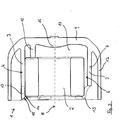
- FIG. 3 the bearing bush 2 is shown with inserted bearing 2 in an axial section along the bearing bush axis 8.
- the bearing 2 is located at the back on the end faces of the pin-shaped spacers 10 and is overlapped by the locking lugs 11 of the sector sections 4 on the front side.
- FIG. 3 clearly shows that the bottom 9 of the bushing 1 at the same time forms the bottom of the can 12 and the gap 17 between the bottom 9 and the bearing 9 via the bulges 6 with the remaining canned space before the camp and radially outside the wall 3 is in communication, so that the bearing bush is pressure-neutral in the can.
- the bottom 9 has a symmetrical elevation 16 in the direction of the bearing 2. This elevation 16 is created by a corresponding bulge of the cavity in the injection mold, in which the can is produced by injecting a plastic molding compound. The bulge improves the flow properties of the plastic during the injection process.
- the contact surfaces 5 are slightly conical. This has the advantage that a uniform stress level in the wall 3 also reaches over a large part of the total axial bearing length.
- the contact surfaces 5 extend between 0.5 ° to 2 ° to the bearing bush axis 8, so that the more elastic front portion of the bearing bush 1 is utilized for the interference fit, since the bearing bush has due to the molded bottom 9 at its other end an increasingly lower elasticity.
- the spacers 10 additionally help hereby that only the elastic front region of the wall 3 is used for the press connection, so that a break of the wall at the bottom area is avoided. In addition, this increases the elasticity.
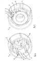
- FIG. 4 shows the bearing bush 1 without bearing in perspective view. Visible is the spigot of the spacers 10, which rise from the bottom 9 in the axial direction.
- the wall 3 of the bearing bush 1 is formed integrally with this bottom 9. Furthermore, this bottom 9 simultaneously forms the bottom of the can 12.
- each sector section 4 protrude in the axial direction with respect to the bottom sections 7, ie are longer than the floor sections 7, the wall 3 between the sector sections 4 arcuate drops.
- each sector section 4 has a radially inwardly directed projection 14, which rests positively on a chamfer on the outer circumference of the bearing 2 and engages over this.
- the free axial ends of the sector sections 4 thus form locking lugs 11, through which the bearing 2 is axially fixable.
- the end faces 15 of the sector sections are chamfered so that the bearing is guided and centered during insertion.
- FIG. 5 shows a bearing bush 1 according to the invention internally in a split tube 12 with inserted bearing 2 in a perspective view.
- the bushing 1 withstands high pressurization and is resistant to media containing additives and / or inhibitors.
- the wall is corrugated in the circumferential direction.
- the vertices of the troughs are then applied to the bearing used.
- the contact surfaces are then formed by the bottom of the troughs.
- Such a bearing bush is used according to the invention at the front end of a split tube. That it is inserted at each axial end, which is directed to the pump in a wet-running motor. Viewed in cross-section, then lie the crests of the wave crests on the inside of the can and fix and center the bearing bush in the can.
Landscapes
- Engineering & Computer Science (AREA)
- General Engineering & Computer Science (AREA)
- Mechanical Engineering (AREA)
- Power Engineering (AREA)
- Sliding-Contact Bearings (AREA)
- Structures Of Non-Positive Displacement Pumps (AREA)
Abstract
Description
- Die vorliegende Erfindung betrifft eine Lagerbuchse zur Aufnahme eines Lagers für einen Rotor einer elektrischen Maschine, insbesondere einer elektromotorisch angetriebenen Kreiselpumpe, mit einer im Wesentlichen zylindrischen Wand aus Kunststoff, die das Lager in seinem eingesetzten Zustand umgibt.
- Lagerbuchsen dienen zur Befestigung von Lagern, durch die eine drehbare Welle geführt ist. Derartige Anordnungen sind insbesondere bei Rotoren von Elektromotoren und Generatoren von Bedeutung, deren Welle an zwei Stellen im Rotorraum gelagert ist. Bei elektromotorisch angetriebenen Kreiselpumpen mit nasslaufendem Rotor sind die Lager und die entsprechenden Lagerbuchsen von dem geförderten Medium umspült. Nassläuferpumpen weisen zur hermetischen Trennung des Rotorraums vom Stator ein Spaltrohr oder einen Spalttopf auf, in dem eine Lagerbuchse eingesetzt und drehfest gehalten ist. Des Weiteren sind Spalttöpfe mit integralen Mitteln zur Befestigung von Lagern an deren Bodenseite bekannt.
- Beispielsweise offenbart die europäische Patentanmeldung
EP 1024 584 A2 einen Spalttopf für eine Kreiselpumpe, in dem zwei Lager zur Lagerung der Motorwelle angeordnet sind, wobei zumindest das am Boden des Spalttopfes angeordnete Lager axial, radial und drehfest formschlüssig in dem Spalttopf gehalten ist. Der Boden des Spalttopfes ist kugelförmig und weist einen Lagersitz zur Aufnahme eines Radialgleitlagers auf. Der Lagersitz hat vier Rastarme, die sich axial in Richtung der Pumpe verjüngend erstrecken. Die Rastarme sind einstückig an den Boden angespritzt und können elastisch nach außen federn. An ihren freien Enden weisen sie jeweils einen nach innen ragenden Vorsprung auf. Jeder Vorsprung greift in eine Ausnehmung des Lagers ein, die an der Außenseite des Lagers eingeformt sind. Zwischen den Rastarmen sind starre Zentrierungselemente angeordnet, durch die Lager radial formschlüssig gehalten und zentriert wird. - Des Weiteren ist aus dem europäischen Patent
EP 1 131 198 B1 eine Lagerbuchse der im einleitenden Teil genannten Gattung bekannt. Sie beschreibt einen Spalttopf einer elektrisch angetriebenen Pumpe, an dessen Boden eine Buchse für ein Lager vorgesehen ist. Diese Buchse ist von einer im Wesentlichen zylindrischen, im Querschnitt kreisförmigen Wand gebildet, die einen Teil des bodenseitigen Endes des Spaltrohes ist. Die Wand besitzt an ihrer in den Rotorraum gerichteten Stirnseite eine Schulter, von der ein ringförmiger Kragen axial absteht. In dem Lagersitz ist ein Lager eingesetzt, das axial über die Schulter und über den Kragen hervorsteht und auf Höhe der Schulter einen Rücksprung aufweist. Durch den Rücksprung ist auch an dem Lager eine Schulter gebildet, so dass auf dieser Schulter und der gegenüberliegenden Schulter des Sitzes, d.h. zwischen dem Lager und dem Kragen ein O-Ring liegt, der das Lager radialfixiert. Der Kragen wird von einem ringförmigen Rückhalteelement umgriffen, das stirnseitig das Lager abdeckt und axial fixiert. - In der Europäischen Patentanmeldung
EP 2 017479 A2 ist ein Spalttopf aus Kunststoff beschrieben, der im Elektromotor den Rotor vom Stator trennt und von der zu pumpenden Flüssigkeit durchflossen ist. An dem dem Pumpenlaufrad abgewandten Ende bildet der Spalttopf einen koaxialen Rohrabschnitt geringeren Durchmessers als der übrige Spalttopf. In diesem Rohrabschnitt liegt ein Radiallager als Kohlegleitlager koaxial ein und nimmt das hintere Ende der nicht dargestellten Motoren- bzw. Pumpenwelle auf. Auf dem Außenmantel des Radiallagers sitzt in einem dem Pumpenläufer zugewandten Bereich ein ringförmiges Fixierelement aus Ethylen-Propylen-Dien-Kautschuk (EPDM) koaxial auf, wobei die Befestigung des Fixierelements auf dem Radiallager form- und/oder kraftschlüssig ist. - Nachteilig bei den bekannten Lagerbuchsen aus Kunststoff ist, dass diese einen viel größeren Ausdehnungskoeffizienten aufweisen als das Material, aus dem das Lager hergestellt ist. Dies führt dazu, dass bei hohen Temperaturen, die durch Reibung am Lager entstehen, insbesondere aber auch aufgrund einer hohen Temperatur des von der Pumpe geförderten Mediums, beispielswiese bei einer Verwendung der Lagerbuchse in einer Heizungspumpe, vorliegen können, ein Lösen des Pressverbundes zwischen Lager und Lagerbuchse erfolgt, so dass ein Spiel zwischen Lager und Lagerbuchse entsteht. Die führt wiederum dazu, dass die Rotorwelle radiales Spiel erhält und dadurch vibrieren kann, woraus ein erhöhter Verschleiß der Bauteile und unangenehme Geräusche resultieren. Demgegenüber kommt es bei niedrigen Temperaturen zu einem zu starken Pressverbund zwischen Lager und Buchse, so dass die Buchse mechanisch überlastet werden und brechen kann.
- Ein weiterer Nachteil des Standes der Technik besteht darin, dass der Pressverbund zwischen Lager und Kunststoffbuchse mit der Zeit nachlässt, da der Kunststoff sich nach und nach verformt, d.h. relaxiert, so dass die das Lager haltenden Kräfte im Kunststoff nachlassen. Die führt ebenfalls dazu, dass sich mit der Zeit zwischen Lager und Buchse ein Spiel ergibt, wodurch Laufunruhe, Geräusche und eine erhöhte mechanische Belastung durch Vibrationen entstehen.
- Aufgabe der vorliegenden Erfindung ist es, eine Lagerbuchse für die Befestigung eines Lagers innerhalb eines Spaltrohes oder Spalttopfes bereitzustellen, die einfach und preiswert herzustellen ist, eine leichte Montage des Lagers ermöglicht oder selbst leicht montiert werden kann, und die einen dauerhaften radialen und axialen Sitz des Lagers gewährt, ohne dass zusätzliche Befestigungsmittel erforderlich sind.
- Diese Aufgabe wird durch eine Lagerbuchse mit den Merkmalen des Anspruchs 1 gelöst. Vorteilhafte Weiterbildungen der Erfindung sind in den Unteransprüchen formuliert.
- Erfindungsgemäß wird eine Lagerbuchse zur Aufnahme eines zylindrischen Lagers für einen Rotor einer elektrischen Maschine, insbesondere einer elektromotorisch angetrieben Kreiselpumpe, vorgeschlagen, mit einer im Wesentlichen zylindrischen Wand aus Kunststoff, die das Lager in seinem eingesetzten Zustand umgibt, wobei die Wand Sektorabschnitte aufweist, deren radial innenliegende Seiten Anlageflächen bilden, zwischen denen das Lager kraftschlüssig haltbar ist, und die Wand zwischen den Sektorabschnitten radial nach außen gerichtete Ausbuchtungen aufweist.
- Die Grundidee der vorliegenden Erfindung besteht darin, die geometrische Form einer Lagerbuchse derart zu wählen, dass sich die in ihr wirkenden Kräfte und Spannung über den gesamten Einsatztemperatur- und Einsatzdruckbereich gleichmäßig verteilen und sich die Lagerbuchse in Abhängigkeit dieser Spannungen und Kräfte zerstörungsfrei elastisch verformen kann sowohl im Falle einer Ausdehnung als auch bei Kontraktion.
- Die wird durch die erfindungsgemäße Geometrie der vorgeschlagenen Lagerbuchse erreicht. Die Sektorabschnitte sind solche Umfangsabschnitte der Wand, an denen ein Lager in der Lagerbuchse nur partiell an der Wand anliegt. Es liegt an den innenliegenden Anlageflächen der Lagerbuchse an, die das Lager kraftschlüssig halten und radial fixieren. Hierdurch werden keine weiteren Mittel zum Halten des Lagers benötigt.
- Die Anlageflächen können in Umfangsrichtung der Wand vergleichsweise breit sein, alternativ jedoch auch sehr schmal ausgebildet sein, so dass ein Lager nur minimal partiell zur Anlage an der Buchse kommt. In den Sektorabschnitten besteht eine Presspassung zwischen Lager und Buchse, während die Wand im Bereich der Ausbuchtungen in einem Abstand zu dem Lager verläuft. Dies bewirkt, dass die von den Sektorabschnitten aufgenommenen Kräfte in diese Wandbereiche zwischen ihnen abgeleitet werden, so dass sich die Wand aufgrund der fehlenden Anlage zum Lager dort leicht elastisch verformen kann.
- Des Weiteren bewirken die Anlageflächen eine Zentrierung des Lagers in der Lagerbuchse, so dass dieses exakt koaxial in der Buchse zum Einliegen kommen kann. Schließlich bewirken die Ausbuchtungen, dass bei mediumumspülten Lagern, wie sie bei Nassläufermotoren für Pumpen vorhanden sind, das Medium durch die Ausbuchtungen hinter das Lager fließen kann. Hierdurch wird eine starke Wärmeabfuhr erreicht und verhindert, dass sich Schmutzpartikel in dem sonst zwischen Lager und Buchse vorhandenen Spalt festsetzen, die zu einer erhöhten Reibung und einem dadurch erhöhten Verschließ führen
- In einer bevorzugten Ausführungsform ist die Wand in Umfangsrichtung zumindest teilweise durchgehend geschlossen. Dies bedeutet, dass die Sektorabschnitte und die zwischen Ihnen liegenden Bereiche ineinander übergehen und die Wand an keiner Stelle entlang ihrer gesamten axialen Erstreckung unterbrochen ist. Dies hat den Vorteil, dass sich die Spannungen und Kräfte über den gesamten Umfang der Wand gleichmäßig verteilen. Es kann dadurch vermieden werden, dass Brüche an Stellen passieren, die höher kraftbeaufschlagt werden als andere Stellen der Wand.
- Des Weiteren ist es von Vorteil, wenn die Ausbuchtungen durch Bogenabschnitte der Wand gebildet sind. Dies bewirkt, dass die von den Sektorabschnitten aufgenommenen Radialkräfte in die zwischen ihnen liegenden Abschnitte, d.h. die Bogenabschnitte, umgeleitet und in Umfangsrichtung verteilt werden. Die Bogenabschnitte schließen sich in diesem Fall unmittelbar an die Sektorabschnitte an. Sie verbinden die zueinander gerichteten Endseiten zweier benachbarter Sektorabschnitte bogenförmig. Insbesondere können die Bogenabschnitte teilkreiszylinderförmig sein, so dass sie die zueinander gerichteten Endseiten zweier benachbarter Sektorabschnitte in der Form eines Teils eines Kreiszylinders miteinander verbinden.
- Vorzugsweise ist der Krümmungsradius der Bogenabschnitte kleiner als der Abstand einer Anlagefläche zur Lagerbuchsenachse, so dass die Ausbuchtungen einen Radius besitzen der kleiner als der durch die Anlageflächen zur Lagerbuchsenachse definierte Radius ist. Da die zueinander gerichteten Endseiten zweier benachbarter Sektorabschnitte durch die Bogenabschnitte verbunden sind, liegen die Endseiten auf dem Kreiszylinder, so dass sich durch den geringeren Krümmungsradius die radialen Ausbuchtungen ergeben, die aus Sicht der Lagerbuchsenachse konkav geformt sind. Insbesondere kann der Krümmungsradius zwischen vier und sechs Zehntel des Abstandes zwischen Anlagefläche und Lagerbuchsenachse betragen.
- In einer bevorzugten Ausführungsvariante kann die Wand in Umfangsrichtung wellenförmig verlaufen. Dies bedeutet, dass die Wand in Umfangsrichtung abwechselnd radial nach innen und radial nach außen verläuft. Die Anlageflächen sind in diesem Fall vergleichsweise schmal werden durch die innenliegenden Seiten der Wellentäler gebildet. Die Wellenform führt zu einer Spannungshomogenität innerhalb der Wand.
- Erfindungsgemäß kann die Wand mehrere Ausbuchtungen aufweisen, insbesondere drei, vier, fünf oder mehr derartiger Ausbuchtungen, die in gleichen Winkelabständen zueinander verteilt sind. Insbesondere kann die Form der Wand epizykloidisch sein, d.h. im Querschnitt eine Epizykloide beschreiben.
- Des Weiteren kann die Dicke der Wand der Sektorabschnitte zumindest teilweise größer sein, als die Dicke der Wand zwischen den Sektorabschnitten. Diese werden dadurch stabil und es wird eine Überbeanspruchung der Sektorabschnitte verhindert, da diese die Pressverbindung mit dem Lager bilden.
- Vorzugsweise weist die Lagerbuchse einen Boden auf. Dies bedeutet, dass sich die Wand von dem Boden in axialer Richtung weg erstreckt und die Lagerbuchse an zumindest einer Seite, der Bodenseite, geschlossen ist. Insbesondere kann die Wand mit dem Boden einstückig ausgebildet sein. Die geometrische Form der Lagerbuche ist dadurch an einem axialen Ende fixiert und hinsichtlich ihrer Elastizität eingeschränkt. In einer vorteilhaften Weiterbildung sind der Boden und die Wand aus demselben Kunststoffmaterial und insbesondere in ein und demselben Spritzvorgang hergestellt. Auf diese Weise ist kein separater Herstellungsschritt erforderlich.
- In einer weiteren vorteilhaften Weiterbildung der erfindungsgemäßen Lagerbuchse weist ihr Boden zumindest einen Abstandshalter auf, an dem das Lager im eingesetzten Zustand anliegt. Beispielsweise kann der Abstandshalter zapfenförmig vom Boden abstehen. Der Abstandshalter bildet zum Einen einen Anschlag für das Lager in axialer Richtung und kann damit zur Aufnahme von Axialkräften dienen, die von dem Lager aufgenommen werden. Zum Anderen bewirkt der Abstandshalter, dass das Lager nicht an dem Boden anliegt. Die hat wiederum zwei Vorteile. Zu einen kann bei mediumumspülten Lagern das durch die Ausbuchtungen geführte Medium hinter dem Lager zirkulieren, so dass ein effektiver Abtransport der Wärme des Lagers erreicht wird, zum anderen wird die T-förmige Übergangsstelle zwischen Wand und Boden nicht überbeansprucht. Dies könnte passieren, wenn im Falle fehlender Abstandshalter das Lager an seinem zum Boden gerichteten Ende eine äußere Umfangskante aufweist, die nicht genug abgerundet oder abgefast ist, so dass das Lager beim Einsetzen in die Lagerbuchse vollumfänglich gegen die Innenrundung drückt, die zur Verstärkung der Übergangsstelle zwischen Wand und Boden dient. Erfindungsgemäß können auch zwei, drei oder mehr Abstandshalter vorgesehen sein. Diese können formgleich ausgebildet sein. Ferner können die Abstandshalter symmetrisch zueinander, insbesondere in gleichen Winkelabständen am Boden angeordnet sein.
- Zusätzlich oder alternativ zu dem/den Abstandshalter(n) können die Sektorabschnitte in ihrer axialen Erstreckungsrichtung gegenüber der Wand im Bereich der Ausbuchtungen verlängert sein und an ihren offenen Enden Rastnasen zum übergreifen eines eingesetzten Lagers aufweisen. Auf diese Weise kann das Lager zwischen den Rastnasen und den Abstandhaltern axial fixiert werden.
- In einer weiteren vorteilhaften Ausführungsvariante können zumindest die Anlageflächen der Sektorabschnitte der Wand in axialer Richtung geringfügig zu Lagerbuchsenachse geneigt sein. Die bewirkt eine gleichmäßige Verteilung der mechanischen Spannung entlang einem Großteil der axialen Länge der Lagerbuchse. Insbesondere kann die Neigung in einem Winkel zwischen 0,05° und 5°, vorzugsweise zwischen 0,5° und 2° zur Lagerbuchsenachse verlaufen.
- Damit die Fläche, mit der die Buchse am Lager zur Anlage kommt, möglichst groß ist, können die Anlageflächen konkav geformt sein. Damit die Befestigung eines Lagers in der Lagerbuchse optimal erfolgt, kann eine Presspassung zwischen diesen Teilen verwendet werden. Hierzu kann der Abstand der Anlageflächen zur Lagerbuchsenachse 0,5mm bis 1 mm kleiner als der Außenradius des Lagers sein.
- Des Weiteren ist es von Vorteil, wenn die Wand an ihrer zur Lagerbuchsenachse gerichteten Innenseite zumindest einen Vorsprung aufweist, der in einer Ausnehmung des Lagers in seinem eingesetzten Zustand formschlüssig einliegen kann. Dieser Formschluss fixiert das Lager in Umfangsrichtung und verhindert eine rotatorische Relativbewegung zwischen Lager und Lagerbuchse. Der Vorsprung kann an der Wand die Gestalt einer Rippe aufweisen, die sich zumindest teilweise entlang der axialen Länge der Wand erstreckt. Alternativ oder kumulativ kann zumindest ein Vorsprung vom Boden in axialer Richtung abstehen und in eine entsprechende Ausnehmung am Lager eingreifen. Beispielsweise kann der Vorsprung an einem sockelförmigen Abstandshalter angeformt sein. Erfindungsgemäß wird zudem ein Spaltrohr für Nassläufermotoren vorgeschlagen, das an wenigstens einem axialen Ende eine Lagerbuchse nach einem der vorherigen Ansprüche aufweist. Die Lagerbuchse kann an diesem einen Ende in das Spaltrohr kraftschlüssig eingesetzt sein oder ein Teil des Spaltrohes bilden. Vorzugsweise sind die Lagerbuchse und der Spalttopf einstückig ausgebildet und bilden baulich eine Einheit, die in einem Herstellungsschritt aus Kunststoff gespritzt oder gegossen werden kann. Vorzugsweise bildet der Boden der Lagerbuchse gleichzeitig zumindest einen Teil des Bodens des Spaltrohrs. Das Spaltrohr stellt in diesem Fall einen Spalttopf dar.
- Vorzugsweise steht die Wand der Lagerbuchse von dem Boden des Spaltrohrs bzw. Spalttopfes in axialer Richtung vor, so dass die Wand der Lagerbuchse bis auf die Anlageflächen nahezu vollständig, d.h. sowohl außerhalb als auch radial innerhalb der Buchse mediumumströmt ist. Auf die Wand, die in diesem Fall vollständig innerhalb des Spaltrohres bzw. Spalttopfs liegt, wirkt in diesem Fall kein Druck, so dass keine zusätzliche mechanische Beanspruchung vorliegt. Alternativ kann die Wand der Lagerbuchse ein Teil der Wand des Spaltrohres bilden. Dies bedeutet, dass das Spaltrohr selbst die Ausbuchtungen, insbesondere den in Umfangsrichtung wellenförmigen Querschnitt aufweist.
- Erfindungsgemäß kann das Spaltrohr auch an seinen beiden axialen Enden eine Lagerbuchse der vorbeschrieben Art aufweisen.
- Weitere Merkmale und Vorteile der Erfindung werden nachfolgend anhand von Ausführungsbeispielen und der beigefügten Figuren erläutert. Gleiche Bezugszahlen bedeuten hierbei gleiche Elemente. Es zeigen:
- Fig. 1:
- Lagerbuchse im radialen Querschnitt ohne Lager
- Fig. 2:
- Lagerbuchse im radialen Querschnitt mit Lager
- Fig. 3:
- Lagerbuchse im axialen Querschnitt mit Lager
- Fig. 4:
- Lagerbuchse in perspektivischer Darstellung ohne Lager
- Fig. 5:
- Lagerbuchse in perspektivischer Darstellung mit Lager
-
Figur 1 zeigt eine erfindungsgemäße Lagerbuchse 1 zur Aufnahme eines zylindrischen Radiallagers 2 für einen nicht dargestellten Rotor eines Nassläufermotors, insbesondere einer elektromotorisch angetriebenen Kreiselpumpe in einem radialen Querschnitt. Die Lagerbuchse ist aus einem thermoplastischen oder duroplastischen Kunststoff hergestellt, und weist eine zylindrischen, umlaufend geschlossen Wand 3 auf, die das Lager 2 in seinem eingesetzten Zustand umgibt, sieheFigur 2 . - Die Wand 3 weist fünf Sektorabschnitte 4 auf, deren radial innenliegende Seiten Anlageflächen 5 bilden, an denen das Lager 2 partiell zur Anlage kommt und zwischen denen das Lager 2 kraftschlüssig haltbar ist bzw. im eingesetzten Zustand gehalten wird. Durch die symmetrische Anordnung der fünf Sektorabschnitte 4 in gleichen Winkelabständen von je 72° wird das Lager 2 innerhalb der Buchse zentriert und radial fixiert. Die Sektorabschnitte 4 bilden eine segmentierte Presspassung über den Umfang des Lagers 2. Die Anlageflächen 5 erstrecken sich über eine im Spritzgusswerkzeug erzeugbare Minimalbreite, wobei der Anlagendurchmesser zusammen mit dem Aussendurchmesser des Lagers 2 eine Presspassung definiert. Die segmentierte Befestigung des Radiallagers 2 in der Lagerbuchse 1 mittels einer Presspassung hat den Vorteil, dass einzelne Segmente im Spritzgusswerkzeug angepasst werden können. Dies führt schließlich zu einem bestmöglichen zentrischen Sitz des Lagers 2.
- Zwischen den Sektorabschnitten 4 besitzt die Wand 3 fünf radial nach außen gerichtete Ausbuchtungen 6, die durch Bogenabschnitte 7 der Wand 3 gebildet sind, die in diesem Ausführungsbeispiel teilkreiszylinderförmig sind. Die Erfindung ist jedoch nicht auf teilkreiszylinderförmige Bogenabschnitte beschränkt. In diesen Bogenabschnitten 7 kann sich die geometrische Struktur der erfindungsgemäßen Lagerbuchse 1 verformen. Hierdurch ergibt sich über den gesamten Einsatzbereich der Lagerbuchse 1 eine Pressverbindung. Die Geometrie der Lagerbuchse 1 ist dadurch spannungs- und dehnungsoptimiert. Die Bereiche 7 zwischen den partiellen Anlageflächen 5 sind derart gestaltet, dass sich aufgrund des eingepressten Lagers 2 ein Zustand ähnlicher Spannungen über den Umfang der Lagerbuchse 1 einstellt. Mit einer derartigen Geometrie können hinreichend große Übermaße zwischen den Passungspartnern realisiert werden, ohne dass die von den Materialien vorgegebenen zulässigen Materialgrenzwerte überschritten werden bzw. der Verbund von Lagerbuchse und Lager aufgehoben wird.
- Der Krümmungsradius der Bogenabschnitte 7 ist kleiner als der Abstand einer Anlagefläche 5 zur Lagerbuchsenachse 8, so dass die Ausbuchtungen 6 einen Radius ra besitzen, der kleiner als der durch die Anlageflächen 5 zur Lagerbuchsenachse 8 definierte Radius ri ist.
- Die zueinander gerichteten Endseiten 13 zweier benachbarter Sektorabschnitte 4 sind über die Bogenabschnitte 7 miteinander verbunden, so dass die Endseiten 13 jeweils auf dem Kreiszylinder liegen, der durch den entsprechenden Bogenabschnitt 7 beschrieben wird. Durch den geringeren Krümmungsradius ra der Bodenabschnitte 7 ergeben sich die radialen Ausbuchtungen 6, die aus Sicht der Lagerbuchsenachse 8 konkav geformt sind, d.h. radial nach außen geformt sind. Bei dem Ausführungsbeispiel in
Figur 4 entspricht der Krümmungsradius ra etwas weniger als die Hälfte des Abstandes ri zwischen Anlagefläche 5 und Lagerbuchsenachse 8. - Die Wand 3 umgibt drei Abstandshalter 10, die sich in gleichen Winkelabständen von 120° von dem in
Figur 1 nicht dargestellten Boden 9 erheben. Sie bilden axiale Anschläge für das Lager 2. Des Weiteren wird die Wand 3 selbst von einer weiteren Wand umgeben, die Teil eines Spaltrohrs 12 ist, mit dem die Lagerbuchse 1 einstückig ausgebildet ist. -
Figur 2 zeigt die Lagerbuchse 1 im radialen Querschnitt mit eingesetztem Lager 2. Die Ausbuchtungen 6 werden durch die Freiräume zwischen den Bogenabschnitten 7 und dem Lager 2 gebildet. Sie dienen dazu, dass die in dem Spaltrohr befindliche Flüssigkeit durch die Ausbuchtungen 6 an dem Lager 2 vorbeiströmen und den rückwärtigen Bereich der Lagerbuchse 1 fluten kann, so dass einerseits eine Kühlung des Lagers erfolgt, andererseits eine gute Schmierung des Lagers und zusätzlich in der Flüssigkeit enthaltene Schmutzpartikel weggeschwemmt werden. - In
Figur 3 ist die Lagerbuchse 2 mit eingesetztem Lager 2 in einem Axialschnitt entlang der Lagerbuchsenachse 8 dargestellt. Das Lager 2 liegt rückseitig an den Stirnseiten der zapfenförmigen Abstandshalter 10 an und wird von den Rastnasen 11 der Sektorabschnitte 4 vorderseitig übergriffen.Figur 3 zeigt deutlich, dass der Boden 9 der Lagerbuchse 1 gleichzeitig den Boden des Spaltrohres 12 bildet und der Zwischenraum 17 zwischen dem Boden 9 und dem Lager 9 über die Ausbuchtungen 6 mit dem übrigen Spaltrohrraum vor dem Lager und radial außerhalb der Wand 3 in Verbindung steht, so dass die Lagerbuchse druckneutral in dem Spaltrohr liegt. Der Boden 9 weist eine symmetrische Erhebung 16 in Richtung des Lagers 2 auf. Diese Erhebung 16 entsteht durch eine entsprechende Auswölbung der Kavität in der Spritzgussform, in der das Spaltrohr durch Einspritzen einer Kunststoffformmasse hergestellt wird. Die Auswölbung verbessert die Fließeigenschaft des Kunststoffes beim Spritzvorgang. - Die Anlageflächen 5 sind leicht konisch ausgebildet. Dies hat den Vorteil, dass ein gleichmäßiges Spannungsniveau in der Wand 3 auch über einen Großteil der gesamten axialen Lagerlänge erreicht. Die Anlageflächen 5 verlaufen zwischen 0,5° bis 2° zur Lagerbuchsenachse 8, so dass der elastischere vordere Bereich der Lagerbuchse 1 für die Presspassung ausgenutzt wird, da die Lagerbuchse aufgrund des angeformten Bodens 9 an ihrem anderen Ende eine zunehmend geringere Elastizität besitzt. Die Abstandshalter 10 helfen hier zusätzlich dadurch, dass nur der elastische vordere Bereich der Wand 3 für die Pressverbindung ausgenutzt wird, so dass ein Bruch der Wand am Bodenbereich vermieden wird. Zusätzlich wird hierdurch die Elastizität erhöht.
-
Figur 4 zeigt die Lagerbuchse 1 ohne Lager in perspektivischer Ansicht. Erkennbar ist die zapfenform der Abstandshalter 10, die sich von dem Boden 9 in axialer Richtung erheben. Die Wand 3 der Lagerbuchse 1 ist mit diesem Boden 9 einstückig ausgebildet. Des Weiteren bildet dieser Boden 9 gleichzeitig den Bodens des Spaltrohres 12. - Schließlich ist in
Figur 4 zu erkennen, dass die Sektorabschnitte 4 gegenüber den Bodenabschnitten 7 in axialer Richtung hervorstehen, d.h. länger sind als die Bodenabschnitte 7, wobei die Wand 3 zwischen den Sektorabschnitten 4 bogenförmig abfällt. An ihrem freien axialen Ende weist jeder Sektorabschnitt 4 einen radial nach innen gerichteten Vorsprung 14 auf, der formschlüssig an einer Fase am Außenumfang des Lagers 2 anliegt und dieses übergreift. Die freien axialen Enden der Sektorabschnitte 4 bilden folglich Rastnasen 11, durch die das Lager 2 axial fixierbar ist. Die Stirnseiten 15 der Sektorabschnitte sind abgeschrägt, damit das Lager beim Einsetzen geführt und zentriert wird. -
Figur 5 zeigt eine erfindungsgemäße Lagerbuchse 1 innenliegend in einem Spaltrohr 12 mit eingesetztem Lager 2 in perspektivischer Ansicht. Die Lagerbuchse 1 hält einer hohen Druckbeaufschlagung stand und ist resistent gegen Medien mit Additiven und/ oder Inhibitoren. - In einer nicht dargestellten Ausführungsform ist die Wand in Umfangsrichtung wellenförmig. Im Querschnitt betrachtet, liegen die Scheitelpunkte der Wellentäler dann an dem eingesetzten Lager an. Bezogen auf die Länge der Lagerbuchse werden die Anlageflächen dann durch die Talsohle der Wellentäler gebildet. Eine derartige Lagerbuche wird erfindungsgemäß am vorderen Ende eines Spaltrohres verwendet. D.h. es ist an jedem axialen Ende eingesetzt, das bei einem Nassläufermotor zur Pumpe gerichtet ist. Im Querschnitt betrachtet, liegen dann die Scheitelpunkte der Wellenberge an der Innenseite des Spaltrohres an und fixieren und zentrieren die Lagerbuchse im Spaltrohr.
-
- 1
- Lagerbuchse
- 2
- Lager
- 3
- Wand
- 4
- Sektorabschnitte
- 5
- Anlageflächen
- 6
- Ausbuchtungen
- 7
- Bogenabschnitte
- 8
- Lagerbuchsenachse
- 9
- Boden
- 10
- Abstandshalter
- 11
- Rastnasen 12 Spalttopf
- 13
- Endseiten
- 14
- Vorsprung
- 15
- Abgeschrägte Stirnseite
- 16
- Erhebung
- 17
- Zwischenraum
Claims (18)
- Lagerbuchse (1) zur Aufnahme eines Lagers (2) für einen Rotor einer elektrischen Maschine, insbesondere einer elektromotorisch angetriebenen Kreiselpumpe, mit einer im Wesentlichen zylindrischen Wand (3) aus Kunststoff, die das Lager (2) in seinem eingesetzten Zustand umgibt, dadurch gekennzeichnet, dass die Wand (3) Sektorabschnitte (4) aufweist, deren radial innenliegende Seiten Anlageflächen (5) bilden, zwischen denen das Lager (2) kraftschlüssig haltbar ist, wobei die Wand (3) zwischen den Sektorabschnitten (4) radial nach außen gerichtete Ausbuchtungen (6) aufweist.
- Lagerbuche (1) nach Anspruch 1, dadurch gekennzeichnet, dass die Wand (3) umlaufend geschlossen ist.
- Lagerbuche (1) nach Anspruch 1 oder 2, dadurch gekennzeichnet, dass die Ausbuchtungen (6) durch Bogenabschnitte (7), insbesondere teilkreiszylinderförmige Bogenabschnitte (7) der Wand (3) gebildet sind.
- Lagerbuche (1) nach Anspruch 3, dadurch gekennzeichnet, dass der Krümmungsradius der Bogenabschnitte (7) kleiner als der Abstand einer Anlagefläche (5) zur Lagerbuchsenachse (8) ist, insbesondere zwischen vier und sechs Zehntel dieses Abstandes beträgt.
- Lagerbuche (1) nach einem der vorherigen Ansprüche, dadurch gekennzeichnet, dass die Wand (3) in Umfangsrichtung wellenförmig verläuft, wobei die Anlageflächen (5) durch die innenliegenden Seiten der Wellentäler gebildet sind.
- Lagerbuchse (1) nach einem der vorherigen Ansprüche, dadurch gekennzeichnet, dass die Wand (3) mehrere Ausbuchtungen aufweist, die in gleichen Winkelabständen zueinander verteilt sind.
- Lagerbuchse (1) nach einem der vorherigen Ansprüche, dadurch gekennzeichnet, dass die Dicke der Wand (3) der Sektorabschnitte (4) zumindest teilweise größer ist, als die Dicke der Wand (3) zwischen den Sektorabschnitten (4).
- Lagerbuchse (1) nach einem der vorherigen Ansprüche, dadurch gekennzeichnet, dass sie einen Boden (9) aufweist, mit dem die Wand (3) einstückig ausgebildet ist.
- Lagerbuchse (1) nach einem der vorherigen Ansprüche, dadurch gekennzeichnet, dass der Boden (9) zumindest einen Abstandshalter (10) aufweist, an dem das Lager (2) im eingesetzten Zustand anliegt.
- Lagerbuchse (1) nach einem der vorherigen Ansprüche, dadurch gekennzeichnet, dass die Sektorabschnitte (4) in axialer Erstreckungsrichtung gegenüber der Wand (3) im Bereich der Ausbuchtungen (6) verlängert sind und an ihren offenen Enden Rastnasen (11) zum übergreifen eines Lagers (2) aufweisen.
- Lagerbuchse (1) nach einem der vorherigen Ansprüche, dadurch gekennzeichnet, dass zumindest die Anlageflächen (5) der Sektorabschnitte (4) der Wand (3) in axialer Richtung geringfügig zu Lagerbuchsenachse (8) geneigt sind, insbesondere in einem Winkel zwischen 0,05° und 5° zur Lagerbuchsenachse (8) verlaufen.
- Lagerbuchse (1) nach einem der vorherigen Ansprüche, dadurch gekennzeichnet, dass die Anlageflächen (5) konkav geformt sind.
- Lagerbuchse (1) nach einem der vorherigen Ansprüche, dadurch gekennzeichnet, dass der Abstand der Anlageflächen (5) zur Lagerbuchsenachse (8) 0,5mm bis 1 mm kleiner als der Außenradius des Lagers (2) ist.
- Lagerbuchse (1) nach einem der vorherigen Ansprüche, dadurch gekennzeichnet, dass die Wand (3) oder der Boden (9) an ihrer/ seiner zur Lagerbuchsenachse (8) gerichteten Seite zumindest einen Vorsprung aufweist, der in einer Ausnehmung des Lagers (2) in seinem eingesetzten Zustand einliegen kann.
- Spaltrohr (12) für eine Kreiselpumpe, dadurch gekennzeichnet, dass es an wenigstens einem axialen Ende eine Lagerbuchse (1) nach einem der vorherigen Ansprüche aufweist.
- Spaltrohr (12) für eine Kreiselpumpe, dadurch gekennzeichnet, dass die Lagerbuchse (1) und das Spaltrohr (12) einstückig sind, wobei der Boden (9) der Lagerbuchse (1) zumindest einen Teil eines Bodens des Spaltrohrs (12) bildet.
- Spaltrohr (12) für eine Kreiselpumpe, dadurch gekennzeichnet, dass die Wand (3) der Lagerbuchse (1) ein Teil der Wand des Spaltrohrs (12) ist.
- Kreiselpumpe mit einem Spaltrohr (12) nach einem der Ansprüche 15 bis 17.
Applications Claiming Priority (1)
| Application Number | Priority Date | Filing Date | Title |
|---|---|---|---|
| DE102011015601A DE102011015601A1 (de) | 2011-03-30 | 2011-03-30 | Lagerbuchse |
Publications (3)
| Publication Number | Publication Date |
|---|---|
| EP2505850A2 true EP2505850A2 (de) | 2012-10-03 |
| EP2505850A3 EP2505850A3 (de) | 2015-09-02 |
| EP2505850B1 EP2505850B1 (de) | 2020-03-04 |
Family
ID=45592160
Family Applications (1)
| Application Number | Title | Priority Date | Filing Date |
|---|---|---|---|
| EP12000540.0A Active EP2505850B1 (de) | 2011-03-30 | 2012-01-27 | Lagerbuchse |
Country Status (2)
| Country | Link |
|---|---|
| EP (1) | EP2505850B1 (de) |
| DE (1) | DE102011015601A1 (de) |
Cited By (3)
| Publication number | Priority date | Publication date | Assignee | Title |
|---|---|---|---|---|
| CN109555728A (zh) * | 2017-05-23 | 2019-04-02 | 何金星 | 一种叶轮壳衬套 |
| CN111853056A (zh) * | 2019-04-30 | 2020-10-30 | 美蓓亚三美株式会社 | 径向引导件 |
| LU102171B1 (de) * | 2020-10-29 | 2022-05-02 | Wilo Se | Kreiselpumpe |
Families Citing this family (3)
| Publication number | Priority date | Publication date | Assignee | Title |
|---|---|---|---|---|
| CN110439846B (zh) * | 2019-09-10 | 2024-11-22 | 绵阳新华内燃机股份有限公司 | 新型电子水泵石墨轴承 |
| DE102021212843A1 (de) | 2021-11-16 | 2023-05-17 | Robert Bosch Gesellschaft mit beschränkter Haftung | Lagervorrichtung, sowie elektrische Maschine beinhaltend eine solche Lager-Vorrichtung und Herstellungsverfahren einer solchen Lager-Vorrichtung |
| DE102023204113B4 (de) * | 2023-05-04 | 2026-02-05 | Brose Fahrzeugteile SE & Co. Kommanditgesellschaft, Coburg | Lageranordnung sowie Fahrzeugsitz mit Lageranordnung |
Citations (3)
| Publication number | Priority date | Publication date | Assignee | Title |
|---|---|---|---|---|
| EP1024584A2 (de) | 1999-01-27 | 2000-08-02 | WILO GmbH | Spalttopf für Kreiselpumpe |
| EP1131198B1 (de) | 1998-11-17 | 2003-02-05 | C.I.M.A. Compagnia Italiana Molle Acciaio S.P.A. | Verfahren zur herstellung eines reibungsdämpfers für waschmaschinen und der mit diesem verfahren hergestellte reibungsdämpfer |
| EP2017479A2 (de) | 2007-07-17 | 2009-01-21 | Wilo Ag | Befestigung eins Radiallagers im Spalttopf |
Family Cites Families (8)
| Publication number | Priority date | Publication date | Assignee | Title |
|---|---|---|---|---|
| DE875594C (de) * | 1951-03-06 | 1953-05-04 | Licentia Gmbh | Drehlageranordnung, insbesondere fuer Motoren von Haushaltsgeraeten |
| DE2416878C3 (de) * | 1974-04-06 | 1980-09-18 | Licentia Patent-Verwaltungs-Gmbh, 6000 Frankfurt | Lageranordnung für einen ein Pumpenaggregat antreibenden Spaltrohrmotor |
| DE2927447A1 (de) * | 1979-07-06 | 1981-01-08 | W & M Engineering Und Automati | Aufnahme fuer ein waelzlager mit sphaerischer aussenflaeche des aussenringes |
| DE29500585U1 (de) * | 1995-01-16 | 1995-03-02 | INA Wälzlager Schaeffler KG, 91074 Herzogenaurach | Distanzring |
| ITPD20010268A1 (it) * | 2001-11-20 | 2003-05-20 | Askoll Holding Srl | Supporto di rotazione perfezionato particolarmente per rotori di motori elettrici di pompe. |
| JP2006340416A (ja) * | 2005-05-31 | 2006-12-14 | Jidosha Denki Kogyo Co Ltd | モータ及びウォッシャポンプ |
| PL1898108T3 (pl) * | 2006-09-07 | 2012-12-31 | Saint Gobain Performance Plastics Rencol Ltd | Kombinowany pierścień montażowy |
| ATE480895T1 (de) * | 2007-09-21 | 2010-09-15 | Grundfos Management As | Spaltrohr eines antriebsmotors für ein pumpenaggregat |
-
2011
- 2011-03-30 DE DE102011015601A patent/DE102011015601A1/de not_active Withdrawn
-
2012
- 2012-01-27 EP EP12000540.0A patent/EP2505850B1/de active Active
Patent Citations (3)
| Publication number | Priority date | Publication date | Assignee | Title |
|---|---|---|---|---|
| EP1131198B1 (de) | 1998-11-17 | 2003-02-05 | C.I.M.A. Compagnia Italiana Molle Acciaio S.P.A. | Verfahren zur herstellung eines reibungsdämpfers für waschmaschinen und der mit diesem verfahren hergestellte reibungsdämpfer |
| EP1024584A2 (de) | 1999-01-27 | 2000-08-02 | WILO GmbH | Spalttopf für Kreiselpumpe |
| EP2017479A2 (de) | 2007-07-17 | 2009-01-21 | Wilo Ag | Befestigung eins Radiallagers im Spalttopf |
Cited By (4)
| Publication number | Priority date | Publication date | Assignee | Title |
|---|---|---|---|---|
| CN109555728A (zh) * | 2017-05-23 | 2019-04-02 | 何金星 | 一种叶轮壳衬套 |
| CN111853056A (zh) * | 2019-04-30 | 2020-10-30 | 美蓓亚三美株式会社 | 径向引导件 |
| LU102171B1 (de) * | 2020-10-29 | 2022-05-02 | Wilo Se | Kreiselpumpe |
| EP3992462A1 (de) * | 2020-10-29 | 2022-05-04 | Wilo Se | Kreiselpumpe |
Also Published As
| Publication number | Publication date |
|---|---|
| EP2505850A3 (de) | 2015-09-02 |
| EP2505850B1 (de) | 2020-03-04 |
| DE102011015601A1 (de) | 2012-10-04 |
Similar Documents
| Publication | Publication Date | Title |
|---|---|---|
| EP2056432B1 (de) | Magnetische Kupplung | |
| EP3032224B1 (de) | Befestigung eines gebermittels an einem ende einer welle | |
| EP2505850B1 (de) | Lagerbuchse | |
| EP2957809B1 (de) | Kupplungselement zur flexiblen verbindung zweier elemente zur führung von medien | |
| EP2500578B1 (de) | Heizungsumwälzpumpe | |
| EP2610497B1 (de) | Pumpenaggregat | |
| EP3646436B1 (de) | Elektromotor | |
| EP0545003B1 (de) | Halterung für einen Elektromotor | |
| EP2899404A1 (de) | Kreiselpumpenlaufrad | |
| EP0622557B1 (de) | Drehelastische Wellenkupplung | |
| EP2283245B1 (de) | Elastischer gelenkkörper | |
| EP2017479B1 (de) | Befestigung eins Radiallagers im Spalttopf | |
| EP1427087A1 (de) | Rotor für einen nasslaufenden Elektromotor | |
| WO2020160888A1 (de) | Steckstück und verwendung des steckstücks | |
| WO2021110200A1 (de) | Rollenfreilaufeinheit für ein fahrzeug | |
| EP1209799B1 (de) | Rotor einer elektrischen Maschine und Verfahren zu dessen Herstellung | |
| DE102018201841B3 (de) | Pumpenlaufrad, Verfahren zur Herstellung eines Pumpenlaufrads und Pumpe mit dem Pumpenlaufrad | |
| DE102018123055B4 (de) | Elastisches Lager | |
| WO2014000973A1 (de) | Pumpe für einen kühlkreislauf eines kraftfahrzeugs | |
| EP3176438B1 (de) | Pumpenaggregat | |
| DE102019106921B4 (de) | Anordnung zum entkoppelten Halten eines Elektromotors und Vorrichtung zum Fördern eines Luftvolumenstromes mit der Anordnung | |
| EP2818722B1 (de) | Kreiselpumpe | |
| DE102011085489A1 (de) | Spielkompensationseinrichtung sowie spielkompensierendes Axiallager, Motor und elektromotorischer Hilfsantrieb | |
| EP2600503B1 (de) | Bürstendeckel für einen bürstenkommutierten Elektromotor und Elektromotor | |
| DE102017100540A1 (de) | Exzenterschneckenpumpe |
Legal Events
| Date | Code | Title | Description |
|---|---|---|---|
| PUAI | Public reference made under article 153(3) epc to a published international application that has entered the european phase |
Free format text: ORIGINAL CODE: 0009012 |
|
| AK | Designated contracting states |
Kind code of ref document: A2 Designated state(s): AL AT BE BG CH CY CZ DE DK EE ES FI FR GB GR HR HU IE IS IT LI LT LU LV MC MK MT NL NO PL PT RO RS SE SI SK SM TR |
|
| AX | Request for extension of the european patent |
Extension state: BA ME |
|
| RIC1 | Information provided on ipc code assigned before grant |
Ipc: F16C 27/02 20060101ALI20150415BHEP Ipc: F04D 29/046 20060101AFI20150415BHEP Ipc: F04D 29/62 20060101ALI20150415BHEP Ipc: F16C 35/02 20060101ALI20150415BHEP Ipc: H02K 5/167 20060101ALI20150415BHEP |
|
| PUAL | Search report despatched |
Free format text: ORIGINAL CODE: 0009013 |
|
| AK | Designated contracting states |
Kind code of ref document: A3 Designated state(s): AL AT BE BG CH CY CZ DE DK EE ES FI FR GB GR HR HU IE IS IT LI LT LU LV MC MK MT NL NO PL PT RO RS SE SI SK SM TR |
|
| AX | Request for extension of the european patent |
Extension state: BA ME |
|
| RIC1 | Information provided on ipc code assigned before grant |
Ipc: F16C 27/02 20060101ALI20150728BHEP Ipc: F04D 29/62 20060101ALI20150728BHEP Ipc: H02K 5/167 20060101ALI20150728BHEP Ipc: F04D 29/046 20060101AFI20150728BHEP Ipc: F16C 35/02 20060101ALI20150728BHEP |
|
| 17P | Request for examination filed |
Effective date: 20160302 |
|
| RBV | Designated contracting states (corrected) |
Designated state(s): AL AT BE BG CH CY CZ DE DK EE ES FI FR GB GR HR HU IE IS IT LI LT LU LV MC MK MT NL NO PL PT RO RS SE SI SK SM TR |
|
| STAA | Information on the status of an ep patent application or granted ep patent |
Free format text: STATUS: EXAMINATION IS IN PROGRESS |
|
| 17Q | First examination report despatched |
Effective date: 20180806 |
|
| GRAP | Despatch of communication of intention to grant a patent |
Free format text: ORIGINAL CODE: EPIDOSNIGR1 |
|
| STAA | Information on the status of an ep patent application or granted ep patent |
Free format text: STATUS: GRANT OF PATENT IS INTENDED |
|
| INTG | Intention to grant announced |
Effective date: 20191118 |
|
| GRAS | Grant fee paid |
Free format text: ORIGINAL CODE: EPIDOSNIGR3 |
|
| GRAA | (expected) grant |
Free format text: ORIGINAL CODE: 0009210 |
|
| STAA | Information on the status of an ep patent application or granted ep patent |
Free format text: STATUS: THE PATENT HAS BEEN GRANTED |
|
| AK | Designated contracting states |
Kind code of ref document: B1 Designated state(s): AL AT BE BG CH CY CZ DE DK EE ES FI FR GB GR HR HU IE IS IT LI LT LU LV MC MK MT NL NO PL PT RO RS SE SI SK SM TR |
|
| REG | Reference to a national code |
Ref country code: GB Ref legal event code: FG4D Free format text: NOT ENGLISH |
|
| REG | Reference to a national code |
Ref country code: CH Ref legal event code: EP |
|
| REG | Reference to a national code |
Ref country code: AT Ref legal event code: REF Ref document number: 1240679 Country of ref document: AT Kind code of ref document: T Effective date: 20200315 |
|
| REG | Reference to a national code |
Ref country code: DE Ref legal event code: R096 Ref document number: 502012015821 Country of ref document: DE |
|
| REG | Reference to a national code |
Ref country code: IE Ref legal event code: FG4D Free format text: LANGUAGE OF EP DOCUMENT: GERMAN |
|
| PG25 | Lapsed in a contracting state [announced via postgrant information from national office to epo] |
Ref country code: RS Free format text: LAPSE BECAUSE OF FAILURE TO SUBMIT A TRANSLATION OF THE DESCRIPTION OR TO PAY THE FEE WITHIN THE PRESCRIBED TIME-LIMIT Effective date: 20200304 Ref country code: FI Free format text: LAPSE BECAUSE OF FAILURE TO SUBMIT A TRANSLATION OF THE DESCRIPTION OR TO PAY THE FEE WITHIN THE PRESCRIBED TIME-LIMIT Effective date: 20200304 Ref country code: NO Free format text: LAPSE BECAUSE OF FAILURE TO SUBMIT A TRANSLATION OF THE DESCRIPTION OR TO PAY THE FEE WITHIN THE PRESCRIBED TIME-LIMIT Effective date: 20200604 |
|
| REG | Reference to a national code |
Ref country code: NL Ref legal event code: MP Effective date: 20200304 |
|
| PG25 | Lapsed in a contracting state [announced via postgrant information from national office to epo] |
Ref country code: GR Free format text: LAPSE BECAUSE OF FAILURE TO SUBMIT A TRANSLATION OF THE DESCRIPTION OR TO PAY THE FEE WITHIN THE PRESCRIBED TIME-LIMIT Effective date: 20200605 Ref country code: BG Free format text: LAPSE BECAUSE OF FAILURE TO SUBMIT A TRANSLATION OF THE DESCRIPTION OR TO PAY THE FEE WITHIN THE PRESCRIBED TIME-LIMIT Effective date: 20200604 Ref country code: LV Free format text: LAPSE BECAUSE OF FAILURE TO SUBMIT A TRANSLATION OF THE DESCRIPTION OR TO PAY THE FEE WITHIN THE PRESCRIBED TIME-LIMIT Effective date: 20200304 Ref country code: SE Free format text: LAPSE BECAUSE OF FAILURE TO SUBMIT A TRANSLATION OF THE DESCRIPTION OR TO PAY THE FEE WITHIN THE PRESCRIBED TIME-LIMIT Effective date: 20200304 Ref country code: HR Free format text: LAPSE BECAUSE OF FAILURE TO SUBMIT A TRANSLATION OF THE DESCRIPTION OR TO PAY THE FEE WITHIN THE PRESCRIBED TIME-LIMIT Effective date: 20200304 |
|
| REG | Reference to a national code |
Ref country code: LT Ref legal event code: MG4D |
|
| PG25 | Lapsed in a contracting state [announced via postgrant information from national office to epo] |
Ref country code: NL Free format text: LAPSE BECAUSE OF FAILURE TO SUBMIT A TRANSLATION OF THE DESCRIPTION OR TO PAY THE FEE WITHIN THE PRESCRIBED TIME-LIMIT Effective date: 20200304 |
|
| PG25 | Lapsed in a contracting state [announced via postgrant information from national office to epo] |
Ref country code: CZ Free format text: LAPSE BECAUSE OF FAILURE TO SUBMIT A TRANSLATION OF THE DESCRIPTION OR TO PAY THE FEE WITHIN THE PRESCRIBED TIME-LIMIT Effective date: 20200304 Ref country code: PT Free format text: LAPSE BECAUSE OF FAILURE TO SUBMIT A TRANSLATION OF THE DESCRIPTION OR TO PAY THE FEE WITHIN THE PRESCRIBED TIME-LIMIT Effective date: 20200729 Ref country code: LT Free format text: LAPSE BECAUSE OF FAILURE TO SUBMIT A TRANSLATION OF THE DESCRIPTION OR TO PAY THE FEE WITHIN THE PRESCRIBED TIME-LIMIT Effective date: 20200304 Ref country code: EE Free format text: LAPSE BECAUSE OF FAILURE TO SUBMIT A TRANSLATION OF THE DESCRIPTION OR TO PAY THE FEE WITHIN THE PRESCRIBED TIME-LIMIT Effective date: 20200304 Ref country code: SM Free format text: LAPSE BECAUSE OF FAILURE TO SUBMIT A TRANSLATION OF THE DESCRIPTION OR TO PAY THE FEE WITHIN THE PRESCRIBED TIME-LIMIT Effective date: 20200304 Ref country code: ES Free format text: LAPSE BECAUSE OF FAILURE TO SUBMIT A TRANSLATION OF THE DESCRIPTION OR TO PAY THE FEE WITHIN THE PRESCRIBED TIME-LIMIT Effective date: 20200304 Ref country code: IS Free format text: LAPSE BECAUSE OF FAILURE TO SUBMIT A TRANSLATION OF THE DESCRIPTION OR TO PAY THE FEE WITHIN THE PRESCRIBED TIME-LIMIT Effective date: 20200704 Ref country code: SK Free format text: LAPSE BECAUSE OF FAILURE TO SUBMIT A TRANSLATION OF THE DESCRIPTION OR TO PAY THE FEE WITHIN THE PRESCRIBED TIME-LIMIT Effective date: 20200304 Ref country code: RO Free format text: LAPSE BECAUSE OF FAILURE TO SUBMIT A TRANSLATION OF THE DESCRIPTION OR TO PAY THE FEE WITHIN THE PRESCRIBED TIME-LIMIT Effective date: 20200304 |
|
| REG | Reference to a national code |
Ref country code: DE Ref legal event code: R097 Ref document number: 502012015821 Country of ref document: DE |
|
| PLBE | No opposition filed within time limit |
Free format text: ORIGINAL CODE: 0009261 |
|
| STAA | Information on the status of an ep patent application or granted ep patent |
Free format text: STATUS: NO OPPOSITION FILED WITHIN TIME LIMIT |
|
| PG25 | Lapsed in a contracting state [announced via postgrant information from national office to epo] |
Ref country code: DK Free format text: LAPSE BECAUSE OF FAILURE TO SUBMIT A TRANSLATION OF THE DESCRIPTION OR TO PAY THE FEE WITHIN THE PRESCRIBED TIME-LIMIT Effective date: 20200304 |
|
| 26N | No opposition filed |
Effective date: 20201207 |
|
| PG25 | Lapsed in a contracting state [announced via postgrant information from national office to epo] |
Ref country code: SI Free format text: LAPSE BECAUSE OF FAILURE TO SUBMIT A TRANSLATION OF THE DESCRIPTION OR TO PAY THE FEE WITHIN THE PRESCRIBED TIME-LIMIT Effective date: 20200304 Ref country code: PL Free format text: LAPSE BECAUSE OF FAILURE TO SUBMIT A TRANSLATION OF THE DESCRIPTION OR TO PAY THE FEE WITHIN THE PRESCRIBED TIME-LIMIT Effective date: 20200304 |
|
| PG25 | Lapsed in a contracting state [announced via postgrant information from national office to epo] |
Ref country code: MC Free format text: LAPSE BECAUSE OF FAILURE TO SUBMIT A TRANSLATION OF THE DESCRIPTION OR TO PAY THE FEE WITHIN THE PRESCRIBED TIME-LIMIT Effective date: 20200304 |
|
| REG | Reference to a national code |
Ref country code: CH Ref legal event code: PL |
|
| PG25 | Lapsed in a contracting state [announced via postgrant information from national office to epo] |
Ref country code: LU Free format text: LAPSE BECAUSE OF NON-PAYMENT OF DUE FEES Effective date: 20210127 |
|
| REG | Reference to a national code |
Ref country code: BE Ref legal event code: MM Effective date: 20210131 |
|
| PG25 | Lapsed in a contracting state [announced via postgrant information from national office to epo] |
Ref country code: LI Free format text: LAPSE BECAUSE OF NON-PAYMENT OF DUE FEES Effective date: 20210131 Ref country code: CH Free format text: LAPSE BECAUSE OF NON-PAYMENT OF DUE FEES Effective date: 20210131 |
|
| PG25 | Lapsed in a contracting state [announced via postgrant information from national office to epo] |
Ref country code: IE Free format text: LAPSE BECAUSE OF NON-PAYMENT OF DUE FEES Effective date: 20210127 |
|
| REG | Reference to a national code |
Ref country code: AT Ref legal event code: MM01 Ref document number: 1240679 Country of ref document: AT Kind code of ref document: T Effective date: 20210127 |
|
| PG25 | Lapsed in a contracting state [announced via postgrant information from national office to epo] |
Ref country code: AT Free format text: LAPSE BECAUSE OF NON-PAYMENT OF DUE FEES Effective date: 20210127 |
|
| PG25 | Lapsed in a contracting state [announced via postgrant information from national office to epo] |
Ref country code: BE Free format text: LAPSE BECAUSE OF NON-PAYMENT OF DUE FEES Effective date: 20210131 |
|
| PG25 | Lapsed in a contracting state [announced via postgrant information from national office to epo] |
Ref country code: HU Free format text: LAPSE BECAUSE OF FAILURE TO SUBMIT A TRANSLATION OF THE DESCRIPTION OR TO PAY THE FEE WITHIN THE PRESCRIBED TIME-LIMIT; INVALID AB INITIO Effective date: 20120127 Ref country code: CY Free format text: LAPSE BECAUSE OF FAILURE TO SUBMIT A TRANSLATION OF THE DESCRIPTION OR TO PAY THE FEE WITHIN THE PRESCRIBED TIME-LIMIT Effective date: 20200304 |
|
| PGFP | Annual fee paid to national office [announced via postgrant information from national office to epo] |
Ref country code: IT Payment date: 20230103 Year of fee payment: 12 |
|
| P01 | Opt-out of the competence of the unified patent court (upc) registered |
Effective date: 20230615 |
|
| PGFP | Annual fee paid to national office [announced via postgrant information from national office to epo] |
Ref country code: GB Payment date: 20231219 Year of fee payment: 13 |
|
| PG25 | Lapsed in a contracting state [announced via postgrant information from national office to epo] |
Ref country code: MK Free format text: LAPSE BECAUSE OF FAILURE TO SUBMIT A TRANSLATION OF THE DESCRIPTION OR TO PAY THE FEE WITHIN THE PRESCRIBED TIME-LIMIT Effective date: 20200304 |
|
| PG25 | Lapsed in a contracting state [announced via postgrant information from national office to epo] |
Ref country code: TR Free format text: LAPSE BECAUSE OF FAILURE TO SUBMIT A TRANSLATION OF THE DESCRIPTION OR TO PAY THE FEE WITHIN THE PRESCRIBED TIME-LIMIT Effective date: 20200304 |
|
| PG25 | Lapsed in a contracting state [announced via postgrant information from national office to epo] |
Ref country code: MT Free format text: LAPSE BECAUSE OF FAILURE TO SUBMIT A TRANSLATION OF THE DESCRIPTION OR TO PAY THE FEE WITHIN THE PRESCRIBED TIME-LIMIT Effective date: 20200304 |
|
| PGFP | Annual fee paid to national office [announced via postgrant information from national office to epo] |
Ref country code: FR Payment date: 20241219 Year of fee payment: 14 |
|
| PG25 | Lapsed in a contracting state [announced via postgrant information from national office to epo] |
Ref country code: IT Free format text: LAPSE BECAUSE OF NON-PAYMENT OF DUE FEES Effective date: 20240127 |
|
| GBPC | Gb: european patent ceased through non-payment of renewal fee |
Effective date: 20250127 |
|
| PG25 | Lapsed in a contracting state [announced via postgrant information from national office to epo] |
Ref country code: GB Free format text: LAPSE BECAUSE OF NON-PAYMENT OF DUE FEES Effective date: 20250127 |
|
| PGFP | Annual fee paid to national office [announced via postgrant information from national office to epo] |
Ref country code: DE Payment date: 20251217 Year of fee payment: 15 |