EP2056432B1 - Magnetische Kupplung - Google Patents
Magnetische Kupplung Download PDFInfo
- Publication number
- EP2056432B1 EP2056432B1 EP07021100.8A EP07021100A EP2056432B1 EP 2056432 B1 EP2056432 B1 EP 2056432B1 EP 07021100 A EP07021100 A EP 07021100A EP 2056432 B1 EP2056432 B1 EP 2056432B1
- Authority
- EP
- European Patent Office
- Prior art keywords
- magnets
- support body
- magnetic coupling
- coupling according
- housing wall
- Prior art date
- Legal status (The legal status is an assumption and is not a legal conclusion. Google has not performed a legal analysis and makes no representation as to the accuracy of the status listed.)
- Active
Links
- 230000008878 coupling Effects 0.000 claims description 66
- 238000010168 coupling process Methods 0.000 claims description 66
- 238000005859 coupling reaction Methods 0.000 claims description 66
- 230000005540 biological transmission Effects 0.000 claims description 4
- 239000010935 stainless steel Substances 0.000 claims description 3
- 229910001220 stainless steel Inorganic materials 0.000 claims description 3
- 238000002347 injection Methods 0.000 claims description 2
- 239000007924 injection Substances 0.000 claims description 2
- 230000002093 peripheral effect Effects 0.000 claims description 2
- 238000004519 manufacturing process Methods 0.000 description 3
- 238000010276 construction Methods 0.000 description 2
- 230000000694 effects Effects 0.000 description 2
- 239000012530 fluid Substances 0.000 description 2
- 229910052751 metal Inorganic materials 0.000 description 2
- 239000002184 metal Substances 0.000 description 2
- 229910000851 Alloy steel Inorganic materials 0.000 description 1
- 230000006978 adaptation Effects 0.000 description 1
- 238000004026 adhesive bonding Methods 0.000 description 1
- 229910052782 aluminium Inorganic materials 0.000 description 1
- XAGFODPZIPBFFR-UHFFFAOYSA-N aluminium Chemical compound [Al] XAGFODPZIPBFFR-UHFFFAOYSA-N 0.000 description 1
- 230000015572 biosynthetic process Effects 0.000 description 1
- 238000005260 corrosion Methods 0.000 description 1
- 230000007797 corrosion Effects 0.000 description 1
- 230000007613 environmental effect Effects 0.000 description 1
- 238000007373 indentation Methods 0.000 description 1
- 230000003993 interaction Effects 0.000 description 1
- 239000000463 material Substances 0.000 description 1
- 238000002360 preparation method Methods 0.000 description 1
- 238000003825 pressing Methods 0.000 description 1
- 125000006850 spacer group Chemical group 0.000 description 1
- 230000003313 weakening effect Effects 0.000 description 1
- 238000003466 welding Methods 0.000 description 1
Images


Classifications
-
- H—ELECTRICITY
- H02—GENERATION; CONVERSION OR DISTRIBUTION OF ELECTRIC POWER
- H02K—DYNAMO-ELECTRIC MACHINES
- H02K49/00—Dynamo-electric clutches; Dynamo-electric brakes
- H02K49/10—Dynamo-electric clutches; Dynamo-electric brakes of the permanent-magnet type
- H02K49/104—Magnetic couplings consisting of only two coaxial rotary elements, i.e. the driving element and the driven element
- H02K49/106—Magnetic couplings consisting of only two coaxial rotary elements, i.e. the driving element and the driven element with a radial air gap
-
- F—MECHANICAL ENGINEERING; LIGHTING; HEATING; WEAPONS; BLASTING
- F04—POSITIVE - DISPLACEMENT MACHINES FOR LIQUIDS; PUMPS FOR LIQUIDS OR ELASTIC FLUIDS
- F04D—NON-POSITIVE-DISPLACEMENT PUMPS
- F04D13/00—Pumping installations or systems
- F04D13/02—Units comprising pumps and their driving means
- F04D13/021—Units comprising pumps and their driving means containing a coupling
- F04D13/024—Units comprising pumps and their driving means containing a coupling a magnetic coupling
- F04D13/027—Details of the magnetic circuit
Definitions
- the invention relates to a magnetic coupling according to the features specified in the preamble of claim 1.
- Magnetic couplings of the type mentioned are used to z. B. to transmit the rotation of a drive shaft without contact on an output shaft.
- a coupling typically consists of an inner coupling part and an outer coupling part, each of which is arranged in a preferably hermetically sealed housing.
- the inner coupling part on an inner support body, which carries distributed over its outer circumference magnets, which are surrounded by a closed metal jacket as a housing.
- the outer coupling part has an annular support body, which is equipped on its inside over the entire circumference with magnets and which is also encapsulated by a coat-like housing.
- the construction In order to achieve the highest possible torque transfer, it is desirable to design the construction so that the distance between the magnets between the inner and outer support body is as small as possible.
- the support body, magnets and housing must be aligned exactly to each other. This is done in the prior art in that the magnets are adhesively secured to the support body before the surrounding housing shell is mounted.
- the distance of the magnets should be as small as possible to the surrounding housing shell to ensure a high magnetic force development to the outside, on the other hand should between the magnet and the housing shell remain a gap in order to mount this at all.
- the magnets are therefore rounded in the inner coupling part in cross section outwardly rounded so as to be able to achieve as constant and small distance to the housing shell over the entire surface of the magnet.
- the magnets of the outer coupling part are recessed inwards in cross-section in order to achieve as constant a distance as possible from the housing jacket.
- the cheaper DE 696 12 834 T2 known magnetic coupling in which cuboidal magnets are used, which, as far as they relate to the inner coupling part, are arranged between an inner support body and an outer housing wall and, as far as the outer coupling part, between a outer support body and an inner housing wall are arranged.
- the present invention seeks to provide a generic magnetic coupling as it US 4,775,291 is known to improve to the effect that on the one hand reduces the manufacturing and assembly costs and on the other hand, the transmittable moment is increased.
- the magnetic coupling on a plurality of permanent magnets which are arranged along the circumference of a housing wall, wherein the magnets bear non-positively on the housing wall.
- the basic idea of the present invention is therefore not to fix the magnets, as in the prior art, by a connection between the support body and the magnet, but with the aid of them the housing wall itself. Since the housing wall is typically formed as a thin stainless steel jacket, this can be pulled, for example in the stretched state on magnets and support body and then relaxed, so that the residual stress of the housing wall produces the adhesion between the magnet, housing wall and support body.
- the magnets therefore only need to be brought into their proper position immediately prior to assembly, after which they are always held securely by the housing wall, not only by the already existing positive connection, but by adhesion. They are thus backlash between the support body and housing wall.
- the coupling according to the invention has an inner coupling part, in which an inner support body is provided, in which an inner support body is provided, on the outer periphery of the magnets are arranged and the radially outwardly on the inside of the surrounding and positively and non-positively holding Housing wall abut. Then the magnets are clamped between the inner support body and the inside of the outer housing wall. The magnetic force is thus directed from the outer housing wall to the outside.
- the coupling according to the invention has an outer coupling part, in which the magnets are arranged on the inside of the inner housing wall and clamped between this and an outer support body.
- the magnetic force is directed from the inner housing wall to the longitudinal center axis of the housing.
- the support body is annular and may be designed to increase the magnetic forces magnetically conductive. However, it can also find a plastic or other component use.
- the annular training leads to a significant weight savings and is particularly advantageous for the inner coupling part applicable.
- In the outer coupling part of the support body is annular at least in the region of the magnets, but it may also be cup-shaped or otherwise formed.
- the magnets are formed substantially cuboid. On an outwardly or inwardly curved shape can be dispensed without weakening the power transmission of the clutch. This has the advantage that no adaptation of the magnets to the housing form is required. It can thus be used cost-effective magnets from mass production.
- cuboidal magnets are also used for the outer coupling part, which then abut outwardly flat on the support body and have an approximately linear contact with the inside of the inner housing wall towards the inside.
- a comparable, but in the direction of force reversed effect occurs, ie the bias of the inner housing wall
- recesses for the magnets are provided in the support body.
- the recesses are provided in the form of grooves in the support body, which extend parallel to the longitudinal center axis of the coupling and which are provided for the positive reception of the magnets.
- Such a groove arrangement has the advantage that a recess, that is to say a groove, serves to arrange a plurality of magnets, since, according to the invention, two or more magnets are arranged one behind the other in a groove in the longitudinal direction of the groove. In this arrangement, all the magnets are the same polarity in a groove.
- the magnets are frictionally held by the bias of the housing wall on or in the support body.
- aids are provided which fix the magnets on the support body until they are held by the housing wall.
- these aids can be removed after application of the housing wall or even remain there.
- Such aids may be, for example, elastic webs, which are arranged in the circumferential direction between the magnets and with which the magnets are arranged at a predetermined distance and supported in this position on the support body.
- such tools can also be mechanical mounts, which are removed after attaching the housing wall again, so hold the magnets in the manner of a gripper during assembly.
- the magnets can be incorporated in a simple manner between these elastic supports located on the support body, wherein the distance between the webs is preferably slightly smaller than the clear width of the magnets in this area, so that the magnets can be held by frictional connection between the webs.
- the wall is part of a housing hermetically surrounding the magnets and advantageously also the support body.
- a housing is preferably made of stainless steel sheet, wherein the steel alloy is tuned in particular with regard to the corrosion resistance to the expected ambient media.
- support body and shaft mechanically non-rotatably connected to each other. It is advantageous, in particular for weight and material saving reasons, not to connect the support body directly to the shaft, but to connect the support body advantageously via frontally arranged force transmission means with a hub, which then sits on a shaft.
- the support body surrounds the magnets on the outside, it is expedient to connect these directly to the end face of the preferably hollow shaft.
- two of the above-described magnetic coupling parts are combined to form a magnetic coupling which is provided for transmitting a rotational movement with an inner coupling part and with an outer coupling part, which are arranged rotatably inside each other and magnetically connected to each other.
- Such a magnetic coupling is particularly advantageously provided for connection between an electric motor and a centrifugal pump in order to reliably isolate the electric motor from the medium conveyed by the centrifugal pump.
- Such an arrangement has the advantage that virtually any engine, so-called standard motors can be used, which are relatively inexpensive, so far expensive on small series and special motors can be dispensed with.
- Such a magnetic coupling moreover has the advantage that it is possible to dispense with the otherwise normally provided with centrifugal pumps canned or otherwise required complex and wear-prone seals.
- An outer part 1 of a magnetic coupling 2 consists of an annular, outer support body 3, which has on its inner side parallel to the longitudinal central axis 4 arranged grooves 5, in which magnets 6 are arranged.
- the magnets 6 are the same Spaced distributed over the inner circumference of the support body 3.
- the magnets 6 have rectangular cross-section and lie with their radially outwardly facing flat side 7 each in a groove 5.
- they bear against the inside of an inner housing wall 9, the part of one of the magnets 6 hermetically forms final housing.
- the inner housing wall 9 pushes the magnets by bias in the grooves 5. Since the magnets have 6 rectangular shape, results in the inner housing wall 9 is an approximately linear contact parallel to the longitudinal center axis. 4
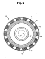
- An inner part 10 of the magnetic coupling 2 has a support body 11, which is also annular and is provided over its outer periphery with parallel to the longitudinal center axis 4 arranged grooves 12 in which magnets 13 are located.
- the magnets 13 correspond in number to the magnets 6 and also have a rectangular cross-section. They are in each case with two edges 14 on the inside of an outer housing wall 15, which also forms part of a magnet 13 hermetically sealed housing and is biased such that it presses the magnets 13 frictionally into the grooves 12.
- the support body 11 is annular and connected to a hollow cylinder 16 which is arranged at a distance within the support body 11 and is provided over part of its length with a profile 17 whose counter profile sits on a shaft and thus forms a shaft-hub connection for a shaft ,
- the structure of the inner part 10 in detail results from Fig. 3 ,
- Fig. 3 In particular, lie in the grooves 12 a plurality of magnets 13 in the longitudinal direction of the groove seen one behind the other.
- the magnets 13 are arranged so that they are magnetized in the radial direction, ie north pole and south pole of the individual magnets are each spaced apart in the radial direction.
- the one after the other in the longitudinal direction Magnets arranged in a groove 12 are aligned in their polarity, ie all magnets in a groove 12 are aligned so that their north poles and their south poles are located on the same side in the radial direction.
- the polarity alternates in the circumferential direction of adjacent magnets, as indicated by the marking S for the south pole and N for north pole in Fig. 3 is shown.
- the magnets 13 are arranged so that their north pole lying radially inward and its south pole is radially outboard, while in the two adjacent grooves 12, the magnets are arranged so that their south pole lying radially inside and its north pole radially outside lying down.
- the arrangement of the polarities in the interaction is based on Fig. 5 can be seen, in which the clutch in the coupled state, that is, when the inner part 10 is disposed within the outer part 1 and rotatably connected by the magnetic forces of the magnets 6 and 13 with this.
- FIG. 5 is exemplified for the magnets 6 and 13 in an enlarged detail the polarity shown.
- FIG. 5 illustrates, both the outer part 1 and the inner part 10 on a hermetically sealed housing, so that the magnets 6, 13 against environmental influences, in particular surrounding fluids are reliably protected.
- a gap is formed, so that the outer and inner parts are not mechanically connected to each other and after overcoming the magnetic force are mutually rotatable.
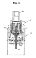
- FIG. 4 In installed condition according to Fig. 4 is the magnetic coupling 2 for non-contact connection between an input shaft 18 and an output shaft 19 is provided.
- the output shaft 19 here forms the drive shaft of a centrifugal pump 20, which is not shown and described in detail here.
- a circular wheel 21 can be seen in the sectional view.
- the support body 11 of the inner part 10 is connected via two end-face annular discs 22 with the hollow cylinder 16.
- these components are made of metal and welded together, the annular discs 22, the support body 11 and the magnets 13 protrude radially and are sealed and firmly connected to the outer housing wall 15 by welding.
- the support body 3 on its side facing away from the pump 20, directly adjoins the hollow shaft 18, which is stepped in this area.
- the support body 3 of the outer part 1 is covered by means of an annular disk 23, so that the magnets 6 are held positively in the grooves 12 in the longitudinal direction of the grooves.
- Supporting body 3, hollow shaft 18, annular disc 23 and the inner housing wall 9 are firmly and tightly welded together, so that here too the magnets 6 are hermetically sealed against fluid influences.
- the magnets 6 and 13 are held in the grooves 5 and 12 by pressing in before mounting the housing walls 9 and 15, respectively.
- auxiliary tools or other aids may be provided to fix this position during assembly, which are removed after application and relaxation of the housing walls 9 and 15 or remain there.
- the depth of the grooves 5 and 12 is chosen so that it is at most 20% of the radial extent of the associated magnets 6 and 13, ie the distance between the flat sides 7 and 8. In the illustrated Embodiments, the groove depth is 10% of the radial extent of the magnets 6 and 13th
Landscapes
- Engineering & Computer Science (AREA)
- Mechanical Engineering (AREA)
- General Engineering & Computer Science (AREA)
- Power Engineering (AREA)
- Dynamo-Electric Clutches, Dynamo-Electric Brakes (AREA)
- Structures Of Non-Positive Displacement Pumps (AREA)
Description
- Die Erfindung betrifft eine magnetische Kupplung gemäß den im Oberbegriff des Anspruchs 1 angegebenen Merkmalen.
- Magnetische Kupplungen der eingangs genannten Art werden eingesetzt, um z. B. die Rotation einer Antriebswelle berührungsfrei auf eine Abtriebswelle zu übertragen. Eine solche Kupplung besteht typischerweise aus einem inneren Kupplungsteil und einem äußeren Kupplungsteil, die jeweils für sich in einem vorzugsweise hermetisch abgeschlossenen Gehäuse angeordnet sind. Dabei weist der innere Kupplungsteil einen inneren Stützkörper auf, der über seinen Außenumfang verteilt Magnete trägt, die von einem geschlossenen Blechmantel als Gehäuse umgeben sind. Der äußere Kupplungsteil weist einen ringförmigen Stützkörper auf, der an seiner Innenseite über den gesamten Umfang mit Magneten bestückt ist und der ebenfalls durch ein mantelartiges Gehäuse gekapselt ist.
- Um eine möglichst hohe Momentenübertragung zu erreichen, ist es erstrebenswert, die Konstruktion so auszubilden, dass der Abstand der Magnete zwischen innerem und äußerem Stützkörper möglichst klein ist. Um dies zu erreichen, sind Stützkörper, Magnete und Gehäuse exakt aufeinander auszurichten. Dies erfolgt beim Stand der Technik dadurch, dass die Magnete durch Kleben auf dem Stützkörper befestigt werden, bevor der umgebende Gehäusemantel montiert wird. Einerseits soll der Abstand der Magnete zum umgebenden Gehäusemantel möglichst gering sein, um eine hohe magnetische Kraftentfaltung nach außen zu gewährleisten, andererseits soll zwischen den Magneten und dem Gehäusemantel ein Spalt verbleiben, um diesen überhaupt montieren zu können.
- Bei bekannten Magnetkupplungen, wie sie beispielsweise aus
US 7,057,320 B2 bekannt sind, sind die Magnete daher beim inneren Kupplungsteil im Querschnitt nach außen hin gerundet geformt, um so über die gesamte Fläche des Magneten einen möglichst konstanten und geringen Abstand zum Gehäusemantel erzielen zu können. Entsprechend sind die Magnete des äußeren Kupplungsteils im Querschnitt nach innen hin eingezogen ausgebildet, um auch hier einen möglichst konstanten Abstand zum Gehäusemantel zu erzielen. - Nachteilig bei dieser bekannten Magnetkupplung ist, dass deren Herstellung recht aufwändig ist, da die Magnete sorgfältig am Stützkörper verklebt werden müssen und darüber hinaus mit einer einachsigen Wölbung versehen sein müssen, die etwa dem Durchmesser des Gehäusemantels an dieser Seite entspricht.
- Aus
US 2006/0290218 A1 zählt es zum Stand der Technik, bei dem inneren Kupplungsteil die Magnete am Stützkörper mittels einer ringförmigen Wand festzulegen, die im Bereich der Magnete Einbuchtungen aufweist, und mit diesen die Magnete gegenüber dem Stützkörper klemmzubefestigen. Die dort beschriebene Konstruktion hat zwar den Vorteil, dass quaderförmige Magnete eingesetzt werden können, allerdings ist die Ausbildung der äußeren Gehäusewand fertigungstechnisch aufwendig und die Montage kompliziert. - Insoweit günstiger ist die aus
DE 696 12 834 T2 bekannte magnetische Kupplung, bei welcher quaderförmige Magnete eingesetzt werden, die, soweit sie den inneren Kupplungsteil betreffen, zwischen einem inneren Stützkörper und einer äußeren Gehäusewand angeordnet sind und die, soweit sie den äußeren Kupplungsteil betreffen, zwischen einem äußeren Stützkörper und einer inneren Gehäusewand angeordnet sind. - Aus
US 4,775,291 ist eine magnetische Kupplung bekannt, bei welcher der innere Kupplungsteil ebenfalls quaderförmige Magnete aufweist, die in Nuten des Stützkörpers eingegliedert sind und die durch die umlaufende äußere Gehäusewandung in dieser Position gehalten werden. - Die aus
US 4,775,291 bekannte Kupplung weist darüber hinaus einen äußeren Kupplungsteil auf, der zwar ebenfalls quaderförmige Magnete hat, die jedoch an der Innenseite des ringförmig außen umlaufenden Tragkörpers durch Kleben befestigt und durch aus Aluminium bestehende Abstandshalter positioniert sind. Die innere Gehäusewandung ist mit Abstand dazu angeordnet. - Vor diesem Hintergrund liegt der vorliegenden Erfindung die Aufgabe zugrunde, eine gattungsgemäße Magnetkupplung wie sie aus
US 4,775,291 bekannt ist, dahingehend zu verbessern, dass einerseits die Herstellungs- und Montagekosten gesenkt und andererseits das übertragbare Moment erhöht wird. - Diese Aufgabe wird gemäß der Erfindung durch die im kennzeichnenden Teil des Anspruchs 1 angegebenen Merkmale gelöst. Vorteilhafte Ausgestaltungen der Erfindung sind in den Unteransprüchen, der nachfolgenden Beschreibung und der Zeichnung angegeben.
- Gemäß der Erfindung weist die magnetische Kupplung eine Vielzahl von Permanentmagneten auf, die längs des Umfangs einer Gehäusewand angeordnet sind, wobei die Magnete kraftschlüssig an der Gehäusewand anliegen. Grundgedanke der vorliegenden Erfindung ist es somit, die Magnete nicht, wie beim Stand der Technik, durch eine Verbindung zwischen Stützkörper und Magneten zu fixieren, sondern mithilfe der Gehäusewand selbst. Da die Gehäusewand typischerweise als dünner Edelstahlmantel ausgebildet ist, kann diese beispielsweise in gedehntem Zustand über Magnete und Stützkörper gezogen und dann entspannt werden, so dass die Eigenspannung der Gehäusewand den Kraftschluss zwischen Magneten, Gehäusewand und Stützkörper herstellt. Die Magneten brauchen daher nur unmittelbar vor der Montage in ihre bestimmungsgemäße Position gebracht zu werden, danach sind sie durch die Gehäusewand stets sicher gehalten, und zwar nicht nur durch den ohnehin gegebenen Formschluss, sondern durch Kraftschluss. Sie liegen somit spielfrei zwischen Stützkörper und Gehäusewand.
- Die erfindungsgemäße Kupplung weist einen inneren Kupplungsteil auf, bei welchem ein innerer Stützkörper vorgesehen ist, bei welchem ein innerer Stützkörper vorgesehen ist, auf dessen Außenumfang die Magnete angeordnet sind und die radial nach außen hin an der Innenseite der diese umgebenden und form- und kraftschlüssig haltenden Gehäusewand anliegen. Dann sind die Magnete zwischen dem inneren Stützkörper und der Innenseite der äußeren Gehäusewand eingespannt. Die magnetische Kraft ist also von der äußeren Gehäusewand nach außen gerichtet.
- Die erfindungsgemäße Kupplung weist einen äußeren Kupplungsteil auf, bei welchem die Magnete an der Innenseite der inneren Gehäusewand angeordnet und zwischen dieser und einem äußeren Stützkörper eingespannt sind. Bei einer solchen Anordnung ist die magnetische Kraft von der inneren Gehäusewand zur Längsmittelachse des Gehäuses gerichtet.
- Der Stützkörper ist ringförmig ausgebildet und kann zur Steigerung der magnetischen Kräfte magnetisch leitend ausgebildet sein. Es kann jedoch auch ein Kunststoff- oder anderes Bauteil Verwendung finden. Die ringförmige Ausbildung führt zu einer deutlichen Gewichtsersparnis und ist insbesondere für den inneren Kupplungsteil vorteilhaft anwendbar. Beim äußeren Kupplungsteil ist der Stützkörper zumindest im Bereich der Magnete ringförmig, er kann jedoch auch topfförmig oder in anderer Weise gebildet sein.
- Bei der erfindungsgemäßen Kupplung sind die Magnete im Wesentlichen quaderförmig ausgebildet. Auf eine nach außen oder innen hin gekrümmte Form kann verzichtet werden, ohne die Kraftübertragung der Kupplung zu schwächen. Dies hat den Vorteil, dass keine Anpassung der Magnete an die Gehäuseform erforderlich ist. Es können somit kostengünstige Magnete aus der Massenfertigung Verwendung finden.
- Bei quaderförmiger Ausbildung der Magnete liegen diese z. B. beim inneren Kupplungsteil mit einer Seite flächig am inneren Stützkörper und mit zwei parallel zur Längsmittelachse der Antriebsanordnung angeordneten äußeren Kanten an der Innenseite der Gehäusewand an, und zwar an der äußeren Gehäusewand. Dadurch, dass die Magnete nur mit ihren Kanten an der Gehäusewand anliegen, kann auf den sonst üblichen, insbesondere zu Montagezwecken erforderlichen Spalt völlig verzichtet werden. Der Gehäusemantel kann vorgespannt über den mit Magneten bestückten inneren Stützkörper gezogen werden, so dass dieser nach Entspannung elastisch rückfedert und auf die Kanten der Magnete drückt und diese damit in ihrer bestimmungsgemäßen Position am Stützkörper festhält.
- Gemäß der Erfindung werden auch für den äußeren Kupplungsteil quaderförmige Magnete eingesetzt, wobei diese dann nach außen hin flächig am Stützkörper anliegen und nach innen hin eine etwa linienförmige Berührung mit der Innenseite der inneren Gehäusewand aufweisen. Auch hier tritt ein vergleichbarer, jedoch in Kraftrichtung umgekehrter Effekt ein, d. h. die Vorspannung der inneren Gehäusewand drückt etwa jeweils in der Mitte auf die Magnete, die sich flächig im äußeren Stützkörper abstützen.
- Gemäß der Erfindung sind im Stützkörper Ausnehmungen für die Magnete vorgesehen. Dabei sind die Ausnehmungen in Form von Nuten im Stützkörper vorgesehen, die sich parallel zur Längsmittelachse der Kupplung erstrecken und die zur formschlüssigen Aufnahme der Magnete vorgesehen sind. Eine solche Nutanordnung hat den Vorteil, dass eine Ausnehmung, also eine Nut, zur Anordnung mehrerer Magnete dient, da nämlich gemäß der Erfindung in einer Nut zwei oder mehr Magnete in Längsrichtung der Nut hintereinander angeordnet sind. Bei dieser Anordnung sind alle Magnete in einer Nut gleich gepolt. Das bedeutet in einer Nut sind alle Magnete so gepolt, dass ihr Nordpol radial innen liegt und ihr Südpol radial außen liegt, während in der nächsten benachbarten Nut vorzugsweise alle Magnete so angeordnet sind, dass ihr Südpol radial innen liegt und ihr Nordpol radial außen liegt. So sind die Magnete über den Umfang abwechselnd gepolt, jedoch innerhalb einer Nut immer gleich gepolt. Eine solche Anordnung hat weiterhin den Vorteil, dass bei Kupplungen, die große Momente übertragen müssen und daher verhältnismäßig lang ausgebildet sind, keine Sondermagnete eingesetzt werden müssen, sondern handelsübliche, quaderförmige Magnete Verwendung finden können, die dann in entsprechender Anzahl hintereinander in der jeweiligen Nut angeordnet werden.
- Grundsätzlich sind gemäß der Erfindung die Magnete durch die Vorspannung der Gehäusewand kraftschlüssig am bzw. im Stützkörper gehalten. Dies schließt jedoch nicht aus, dass zu Montagezwecken Hilfsmittel vorgesehen sind, welche die Magnete so lange am Stützkörper fixieren, bis diese durch die Gehäusewand gehalten werden. Diese Hilfsmittel können je nach Anwendung nach Anbringen der Gehäusewand entfernt werden oder auch dort verbleiben. Solche Hilfsmittel gemäß der Erfindung können beispielsweise elastische Stege sein, welche in Umfangsrichtung zwischen den Magneten angeordnet sind und mit denen die Magnete in einem vorbestimmten Abstand angeordnet und in dieser Position am Stützkörper gehaltert sind. Solche Hilfsmittel können jedoch auch mechanische Halterungen sein, die nach Anbringen der Gehäusewand wieder entfernt werden, also die Magnete nach Art eines Greifers während der Montage halten.
- Beim Einsatz der vorgenannten elastischen Stege ist es besonders vorteilhaft, wenn diese fest mit dem Stützkörper verbunden sind, vorzugsweise einstückig mit diesem als Kunststoffspritzgussteil ausgebildet sind. Dann können die Magnete in einfacher Weise zwischen diesen am Stützkörper befindlichen elastischen Stege eingegliedert werden, wobei der Abstand der Stege vorzugsweise etwas kleiner als die lichte Weite der Magnete in diesem Bereich ist, damit die Magnete durch Kraftschluss zwischen den Stegen gehalten werden können.
- Wenn die Magnete innerhalb des Stützkörpers in einer Ausnehmung liegen, also beispielsweise einer Nut, dann ist es von Vorteil, wenn ein Magnet mit maximal 20 % seiner radialen Erstreckung innerhalb der Ausnehmung liegt und im Übrigen, also mit minimal 80 % seiner radialen Erstreckung diese überragt, also vom Außen- bzw. Innenumfang des Stützkörpers radial vorsteht. Da Magnete typischerweise feuchtigkeitsempfindlich sind, ist gemäß einer Weiterbildung der Erfindung vorgesehen, dass die Wand Teil eines die Magnete und vorteilhaft auch den Stützkörper hermetisch umgebenden Gehäuses ist. Ein solches Gehäuse besteht vorzugsweise aus Edelstahlblech, wobei die Stahllegierung insbesondere hinsichtlich der Korrosionsbeständigkeit auf die zu erwartenden Umgebungsmedien abgestimmt ist.
- Um eine Drehmomentübertragung zwischen Stützkörper und einer Antriebs- oder Abtriebswelle zu gewährleisten, sind Stützkörper und Welle drehfest mechanisch miteinander zu verbinden. Dabei ist es insbesondere aus Gewichts- und Materialersparnisgründen vorteilhaft, den Stützkörper nicht unmittelbar mit der Welle zu verbinden, sondern den Stützkörper vorteilhaft über stirnseitig angeordnete Kraftübertragungsmittel mit einer Nabe zu verbinden, die dann auf einer Welle sitzt. Für eine Antriebsanordnung, bei der der Stützkörper die Magnete außen umgibt, ist es zweckmäßig, diesen direkt mit der vorzugsweise hohlen Welle stirnseitig zu verbinden.
- Gemäß der Erfindung werden zwei der vorbeschriebenen magnetischen Kupplungsteile zu einer magnetischen Kupplung vereint, die zur Übertragung einer Rotationsbewegung mit einem inneren Kupplungsteil und mit einem äußeren Kupplungsteil versehen ist, die drehbar ineinander angeordnet und magnetisch miteinander antriebsverbunden sind.
- Besonders vorteilhaft ist eine solche magnetische Kupplung zur Verbindung zwischen einem Elektromotor und einer Kreiselpumpe vorgesehen, um den Elektromotor gegenüber dem von der Kreiselpumpe geförderten Medium zuverlässig zu isolieren. Eine solche Anordnung hat den Vorteil, dass quasi beliebige Motoren, so auch sogenannte Normmotoren eingesetzt werden können, die vergleichsweise kostengünstig sind, also insoweit auf teure Kleinserien- und Spezialmotoren verzichtet werden kann. Eine solche magnetische Kupplung hat darüber hinaus den Vorteil, dass auf das sonst bei Kreiselpumpen typischerweise vorgesehene Spaltrohr oder die sonst erforderlichen aufwändigen und verschleißanfälligen Dichtungen verzichtet werden kann.
- Die Erfindung ist nachfolgend anhand eines in der Zeichnung dargestellten Ausführungsbeispiels näher erläutert. Es zeigen:
- Fig. 1
- einen äußeren Kupplungsteil im Querschnitt,
- Fig. 2
- einen inneren Kupplungsteil im Querschnitt,
- Fig. 3
- einen inneren Kupplungsteil in perspektivischer Ansicht mit teilweise geschnittenem Gehäuse,
- Fig. 4
- einen Längsschnitt durch eine Kreiselpumpe mit einer daran angeschlossenen magnetischen Kupplung und
- Fig. 5
- die inneren und äußeren Kupplungsteile in Wirkverbindung im Querschnitt.
- Ein Außenteil 1 einer magnetischen Kupplung 2 besteht aus einem ringförmigen, äußeren Stützkörper 3, der an seiner Innenseite parallel zur Längsmittelachse 4 angeordnete Nuten 5 aufweist, in denen Magnete 6 angeordnet sind. Durch die Nuten 5 sind die Magnete 6 in gleichem Abstand verteilt über den Innenumfang des Stützkörpers 3 angeordnet. Die Magnete 6 haben rechteckigen Querschnitt und liegen mit ihrer radial nach außen weisenden Flachseite 7 jeweils in einer Nut 5. An der davon abgewandten, nach innen weisenden Flachseite 8 liegen sie an der Innenseite einer inneren Gehäusewand 9 an, die Teil eines die Magnete 6 hermetisch abschließenden Gehäuses bildet. Die innere Gehäusewand 9 drückt die Magnete durch Vorspannung in die Nuten 5. Da die Magnete 6 rechteckige Form haben, ergibt sich an der inneren Gehäusewand 9 eine etwa linienförmige Anlage parallel zur Längsmittelachse 4.
- Ein Innenteil 10 der magnetischen Kupplung 2 weist einen Stützkörper 11 auf, der ebenfalls ringförmig ausgebildet ist und über seinen Außenumfang mit parallel zur Längsmittelachse 4 angeordneten Nuten 12 versehen ist, in denen Magnete 13 liegen. Die Magnete 13 entsprechen in ihrer Anzahl der der Magnete 6 und haben ebenfalls rechteckigen Querschnitt. Sie liegen jeweils mit zwei Kanten 14 an der Innenseite einer äußeren Gehäusewand 15 an, die ebenfalls Teil eines die Magnete 13 hermetisch abschließenden Gehäuses bildet und derart vorgespannt ist, dass sie die Magnete 13 kraftschlüssig in die Nuten 12 presst. Der Stützkörper 11 ist ringförmig und mit einem Hohlzylinder 16 verbunden, der mit Abstand innerhalb des Stützkörpers 11 angeordnet ist und über einen Teil seiner Länge mit einem Profil 17 versehen ist, dessen Gegenprofil auf einer Welle sitzt und somit eine Wellen-Nabenverbindung für eine Welle bildet. Der Aufbau des Innenteils 10 im Einzelnen ergibt sich aus
Fig. 3 . - Wie
Fig. 3 insbesondere zeigt, liegen in den Nuten 12 mehrere Magnete 13 in Längsrichtung der Nut gesehen hintereinander. Die Magnete 13 sind dabei so angeordnet, dass sie in radialer Richtung magnetisiert sind, d.h. Nordpol und Südpol der einzelnen Magnete sind jeweils in radialer Richtung voneinander beabstandet. Die in Längsrichtung hintereinander in einer Nut 12 angeordneten Magnete sind in ihrer Polarität gleich ausgerichtet, d.h. alle Magnete in einer Nut 12 sind so ausgerichtet, dass ihre Nordpole und ihre Südpole an derselben Seite in radialer Richtung gelegen sind. Dabei wechselt sich die Polarität in Umfangsrichtung nebeneinander liegende Magnete ab, wie durch die Kennzeichnung S für Südpol und N für Nordpol inFig. 3 dargestellt ist. Das bedeutet in einer Nut sind die Magnete 13 so angeordnet, dass ihr Nordpol radial innen liegend und ihr Südpol radial außen liegend ist, während in den beiden benachbarten Nuten 12 die Magnete so angeordnet sind, dass ihr Südpol radial innen liegend und ihr Nordpol radial außen liegend ist. Die Anordnung der Polaritäten im Zusammenwirken ist anhand vonFig. 5 ersichtlich, in welcher die Kupplung im gekuppelten Zustand, d. h. wenn das Innenteil 10 innerhalb des Außenteils 1 angeordnet und durch die magnetischen Kräfte der Magnete 6 und 13 drehfest mitdiesem verbunden ist. InFigur 5 ist beispielhaft für die Magnete 6 und 13 in einer Ausschnittsvergrößerung die Polung dargestellt. Es ist zu verstehen, dass bei den zu diesen jeweils benachbarten Magneten die Polarität genau umgekehrt ist, d.h. die Nordpole liegen radial außen und die Südpole radial innen. So sind die Magnete in Umfangsrichtung immer abwechselnd gepolt. - Wie
Fig. 5 verdeutlicht, weisen sowohl das Außenteil 1 als auch das Innenteil 10 ein hermetisch dichtes Gehäuse auf, so dass die Magnete 6, 13 gegenüber Umwelteinflüssen, insbesondere umgebenden Fluiden zuverlässig geschützt sind. Zwischen der äußeren Gehäusewand 15 des Innenteils 10 und der inneren Gehäusewand 9 des Außenteils 1 ist ein Spalt gebildet, so dass Außen- und Innenteil mechanisch nicht miteinander verbunden sind und nach Überwindung der Magnetkraft zueinander rotierbar sind. - In eingebautem Zustand gemäß
Fig. 4 ist die magnetische Kupplung 2 zur berührungsfreien Verbindung zwischen einer Eingangswelle 18 und einer Abtriebswelle 19 vorgesehen. Die Abtriebswelle 19 bildet hier die Antriebswelle einer Kreiselpumpe 20, die hier nicht im Einzelnen dargestellt ist und beschrieben ist. In der Schnittdarstellung erkennbar ist ein Kreiselrad 21. Wie die Schnittdarstellung nachFig. 4 weiter zeigt, ist der Stützkörper 11 des Innenteils 10 über zwei stirnseitige Ringscheiben 22 mit dem Hohlzylinder 16 verbunden. In der vorstehend beschriebenen Ausführung sind diese Bauteile aus Metall und fest miteinander verschweißt, wobei die Ringscheiben 22 den Stützkörper 11 und die Magnete 13 radial überragen und mit der äußeren Gehäusewand 15 durch Schweißen dicht und fest verbunden sind. - Beim Außenteil 2 hingegen schließt der Stützkörper 3 an seiner von der Pumpe 20 abgewandten Seite unmittelbar an die Hohlwelle 18 an, die in diesem Bereich abgestuft ausgebildet ist. Zur anderen Seite hin ist der Stützkörper 3 des Außenteils 1 mittels einer Ringscheibe 23 abgedeckt, so dass die Magnete 6 in den Nuten 12 auch in Längsrichtung der Nuten formschlüssig gehalten sind. Stützkörper 3, Hohlwelle 18, Ringscheibe 23 und die innere Gehäusewand 9 sind fest und dicht miteinander verschweißt, so dass auch hier die Magnete 6 hermetisch gegenüber Fluideinflüssen abgeschlossen sind.
- Bei der dargestellten Kupplung sind die Magnete 6 und 13 vor Montage der Gehäusewände 9 bzw. 15 in den Nuten 5 bzw. 12 durch Einpressen gehalten. Es können jedoch auch Hilfswerkzeuge oder andere Hilfsmittel vorgesehen sein, um diese Stellung während der Montage zu fixieren, die entweder nach Aufbringen und Entspannen der Gehäusewände 9 und 15 entfernt werden oder dort verbleiben.
- Die Tiefe der Nuten 5 und 12 ist so gewählt, dass sie maximal 20 % der radialen Erstreckung der zugehörigen Magnete 6 bzw. 13 beträgt, also den Abstand zwischen den Flachseiten 7 und 8. Bei den dargestellten Ausführungsbeispielen beträgt die Nuttiefe 10 % der radialen Erstreckung der Magnete 6 bzw. 13.
-
- 1 -
- Außenteil
- 2 -
- magnetische Kupplung
- 3 -
- Stützkörper
- 4 -
- Längsmittelachse
- 5 -
- Nuten
- 6 -
- Magnete
- 7 -
- nach außen weisende Flachseite
- 8 -
- nach innen weisende Flachseite
- 9 -
- innere Gehäusewand
- 10 -
- Innenteil
- 11 -
- Stützkörper
- 12 -
- Nuten
- 13 -
- Magnete
- 14 -
- Kanten
- 15 -
- äußeren Gehäusewand
- 16 -
- Hohlzylinder
- 17 -
- Profil
- 18 -
- Eingangswelle
- 19 -
- Abtriebswelle
- 20 -
- Kreiselpumpe
- 21 -
- Kreiselrad
- 22 -
- Ringscheiben
- 23 -
- Ringscheibe
- N -
- Nordpol
- S -
- Südpol
Claims (12)
- Magnetische Kupplung (2) zur Übertragung einer Rotationsbewegung, mit einem inneren Kupplungsteil (10) und mit einem äußeren Kupplungsteil (1), die drehbar ineinander angeordnet und magnetisch miteinander antriebsverbunden sind, wobei das innere Kupplungsteil (10) einen inneren Stützkörper (11) und eine äußere Gehäusewand (15) aufweist, zwischen denen quaderförmig ausgebildete Permanentmagnete (13) eingespannt sind und das äußere Kupplungsteil (1) einen äußeren ringförmigen Stützkörper (3) und eine innere Gehäusewand (9) aufweist, zwischen denen quaderförmig ausgebildete Permanentmagnete (6) eingespannt sind, die mit ihren nach innen weisenden Flächen (8) an der inneren Gehäusewand (9) des äußeren Kupplungsteils (1) anliegen, wobei im inneren Stützkörper (11) und im äußeren Stützkörper (3) Nuten (5, 12) zur formschlüssigen Aufnahme der Magnete (6, 13) ausgebildet sind und in einer Nut (5, 12) zwei oder mehr Magnete (6, 13) in Längsrichtung der Nut (5, 12) hintereinander angeordnet sind, wobei alle Magnete (6, 13) in einer Nut (5, 12) in gleiche Richtung gepolt sind.
- Magnetische Kupplung nach Anspruch 1, dadurch gekennzeichnet, dass der innere Stützkörper (11) ringförmig ausgebildet ist.
- Magnetische Kupplung nach Anspruch 1 oder 2, dadurch gekennzeichnet, dass der Stützkörper (3, 11) magnetisch leitend ausgebildet ist.
- Magnetische Kupplung nach einem der vorhergehenden Ansprüche, dadurch gekennzeichnet, dass die Magnete (13) des inneren Kupplungsteils (10) mit zwei äußeren Kanten (14) an der Innenseite der äußeren Gehäusewand (15) des inneren Kupplungsteils (10) anliegen.
- Magnetische Kupplung nach einem der vorhergehenden Ansprüche, dadurch gekennzeichnet, dass die Magnete (6, 13) in Umfangsrichtung durch elastische Stege beabstandet und gehalten sind.
- Magnetische Kupplung nach Anspruch 5, dadurch gekennzeichnet, dass die elastischen Stege fest mit dem Stützkörper (3, 11) verbunden sind.
- Magnetische Kupplung nach Anspruch 5 oder 6, dadurch gekennzeichnet, dass die elastischen Stege mit dem Stützkörper (3, 11) einstückig als Kunststoffspritzteil ausgebildet sind.
- Magnetische Kupplung nach einem der vorhergehenden Ansprüche 8 - 10, dadurch gekennzeichnet, dass ein Magnet (6, 13) mit maximal 20% seiner radialen Erstreckung innerhalb der Nut (5, 12) liegt.
- Magnetische Kupplung nach einem der vorhergehenden Ansprüche, dadurch gekennzeichnet, dass die Gehäusewand (9, 15) Teil eines die Magnete (6, 13) und den Stützkörper (3, 11) hermetisch umgebenden Gehäuses ist.
- Magnetische Kupplung nach Anspruch 9, dadurch gekennzeichnet, dass das Gehäuse aus Edelstahlblech gebildet ist.
- Magnetische Kupplung nach einem der vorhergehenden Ansprüche, dadurch gekennzeichnet, dass der Stützkörper (3, 11) drehfest mit einer Welle (18, 19) verbunden ist.
- Magnetische Kupplung nach einem der vorhergehenden Ansprüche, dadurch gekennzeichnet, dass sie die Verbindung zwischen einem Elektromotor und einer Kreiselpumpe (20) bildet.
Priority Applications (4)
| Application Number | Priority Date | Filing Date | Title |
|---|---|---|---|
| EP07021100.8A EP2056432B1 (de) | 2007-10-29 | 2007-10-29 | Magnetische Kupplung |
| PCT/EP2008/009090 WO2009056271A1 (de) | 2007-10-29 | 2008-10-28 | Magnetische antriebsanordnung |
| CN2008801137061A CN101842968B (zh) | 2007-10-29 | 2008-10-28 | 磁驱动装置 |
| US12/740,549 US8610324B2 (en) | 2007-10-29 | 2008-10-28 | Magnetic drive arrangement |
Applications Claiming Priority (1)
| Application Number | Priority Date | Filing Date | Title |
|---|---|---|---|
| EP07021100.8A EP2056432B1 (de) | 2007-10-29 | 2007-10-29 | Magnetische Kupplung |
Publications (2)
| Publication Number | Publication Date |
|---|---|
| EP2056432A1 EP2056432A1 (de) | 2009-05-06 |
| EP2056432B1 true EP2056432B1 (de) | 2015-04-15 |
Family
ID=39227068
Family Applications (1)
| Application Number | Title | Priority Date | Filing Date |
|---|---|---|---|
| EP07021100.8A Active EP2056432B1 (de) | 2007-10-29 | 2007-10-29 | Magnetische Kupplung |
Country Status (4)
| Country | Link |
|---|---|
| US (1) | US8610324B2 (de) |
| EP (1) | EP2056432B1 (de) |
| CN (1) | CN101842968B (de) |
| WO (1) | WO2009056271A1 (de) |
Families Citing this family (21)
| Publication number | Priority date | Publication date | Assignee | Title |
|---|---|---|---|---|
| US20130119804A1 (en) * | 2009-11-09 | 2013-05-16 | Andrew Boyd French | Magnetic coupler |
| KR101134970B1 (ko) * | 2009-11-19 | 2012-04-09 | 현대자동차주식회사 | 전기식 워터 펌프 |
| KR101134969B1 (ko) | 2009-11-19 | 2012-04-09 | 현대자동차주식회사 | 전기식 워터 펌프의 고정자 제작 방법 |
| KR101134968B1 (ko) | 2009-11-19 | 2012-04-09 | 현대자동차주식회사 | 전기식 워터 펌프 |
| JP5265615B2 (ja) * | 2010-05-13 | 2013-08-14 | 正志 西村 | 永久磁石埋め込み回転子 |
| DE102011003400A1 (de) * | 2011-01-31 | 2012-08-02 | Ate Antriebstechnik Und Entwicklungs Gmbh | Elektromotor |
| BR112013006692B1 (pt) | 2011-02-10 | 2021-07-13 | Nipro Corporation | Configuração de bomba |
| US20120313472A1 (en) * | 2011-06-13 | 2012-12-13 | Baker Hughes Incorporated | Magnetic particle induced plugging resistant magnetic coupling |
| DE102011109228A1 (de) * | 2011-08-01 | 2013-02-28 | J.N. Eberle Federnfabrik Gmbh | Elektrische Maschine sowie Verfahren zur Montage einer elektrischen Maschine |
| US20130123026A1 (en) * | 2011-11-15 | 2013-05-16 | Norman Lane Purdy | Magnetic drive power transfer system |
| CN102828973B (zh) * | 2012-09-20 | 2015-06-10 | 湖南大学 | 永磁同步磁悬浮高速电机直驱空气压缩机 |
| US20150333584A1 (en) * | 2014-05-15 | 2015-11-19 | Calnetix Technologies, Llc | High speed brushless dc electric machine |
| US9476783B2 (en) * | 2014-05-16 | 2016-10-25 | Baldor Electric Company | System and method for magnetically coupling loads to prime movers and detecting transmitted torque |
| EP2960515B1 (de) | 2014-06-24 | 2018-10-31 | Grundfos Holding A/S | Magnetische Kupplung |
| DE102016015731B4 (de) | 2016-01-11 | 2023-08-10 | Valeo Thermal Commercial Vehicles Germany GmbH | Magnetkupplungsrotor |
| DE102016100375B4 (de) * | 2016-01-11 | 2020-10-08 | Valeo Thermal Commercial Vehicles Germany GmbH | Magnetkupplungsrotor |
| US11522436B2 (en) | 2019-10-15 | 2022-12-06 | Darrell Schmidt Enterprises, Inc. | Permanently magnetized enhanced generator |
| US11296588B2 (en) | 2019-10-15 | 2022-04-05 | Darrell Schmidt Enterprises, Inc. | Magnetic coupler |
| CN113014013B (zh) * | 2019-12-20 | 2023-06-09 | 新疆金风科技股份有限公司 | 转子支架、转子、电机及风力发电机组 |
| CN112494804B (zh) * | 2020-11-23 | 2023-09-19 | 苏州恒瑞宏远医疗科技有限公司 | 一种适用于磁驱动离心血泵的驱动转盘及装置 |
| RU210503U1 (ru) * | 2021-12-20 | 2022-04-18 | Александр Семенович Дубовик | Магнитная муфта центробежного насоса |
Citations (3)
| Publication number | Priority date | Publication date | Assignee | Title |
|---|---|---|---|---|
| US4775291A (en) * | 1987-07-27 | 1988-10-04 | Binks Manufacturing Company | Magnetic clutch drive and thrust balancing mechanism for rotary pumps |
| DE69612834T2 (de) * | 1995-10-17 | 2001-12-13 | Paul Richard Stonestreet | Magnetische kupplung |
| US20030137203A1 (en) * | 2002-01-23 | 2003-07-24 | Chang Chio Sung | Magnetic material fixing structure of motor rotor |
Family Cites Families (8)
| Publication number | Priority date | Publication date | Assignee | Title |
|---|---|---|---|---|
| US5289657A (en) * | 1992-03-13 | 1994-03-01 | The Standard Products Company | Refrigerator gasket and retainer |
| EP1346458B1 (de) * | 2000-11-30 | 2008-11-12 | C.D.R. Pompe S.P.A. | Mechanische, magnetkraftbetriebene antriebsvorrichtung |
| DE50101980D1 (de) * | 2001-02-27 | 2004-05-19 | Grundfos As | Verfahren zur Herstellung eines gekapselten Rotors eines Permanentmagnetmotors |
| JP2002354721A (ja) * | 2001-05-29 | 2002-12-06 | Hitachi Ltd | 永久磁石式回転子を備えた回転電機 |
| DE10301079A1 (de) * | 2003-01-14 | 2004-07-29 | Siemens Ag | Flächige Anordnung von Permanentmagneten |
| DE102004026453A1 (de) * | 2003-06-04 | 2004-12-30 | Luk Lamellen Und Kupplungsbau Beteiligungs Kg | Eletrische Maschine, Verfahren zu deren Herstellung sowie Vorrichtung zur Herstellung eines Sekundärteils für eine elektrische Maschine |
| US7183683B2 (en) * | 2005-06-23 | 2007-02-27 | Peopleflo Manufacturing Inc. | Inner magnet of a magnetic coupling |
| US7861540B2 (en) * | 2008-01-25 | 2011-01-04 | Hamilton Storage Technologies, Inc. | Automated storage and retrieval system for storing biological or chemical samples at ultra-low temperatures |
-
2007
- 2007-10-29 EP EP07021100.8A patent/EP2056432B1/de active Active
-
2008
- 2008-10-28 WO PCT/EP2008/009090 patent/WO2009056271A1/de active Application Filing
- 2008-10-28 US US12/740,549 patent/US8610324B2/en active Active
- 2008-10-28 CN CN2008801137061A patent/CN101842968B/zh active Active
Patent Citations (3)
| Publication number | Priority date | Publication date | Assignee | Title |
|---|---|---|---|---|
| US4775291A (en) * | 1987-07-27 | 1988-10-04 | Binks Manufacturing Company | Magnetic clutch drive and thrust balancing mechanism for rotary pumps |
| DE69612834T2 (de) * | 1995-10-17 | 2001-12-13 | Paul Richard Stonestreet | Magnetische kupplung |
| US20030137203A1 (en) * | 2002-01-23 | 2003-07-24 | Chang Chio Sung | Magnetic material fixing structure of motor rotor |
Also Published As
| Publication number | Publication date |
|---|---|
| CN101842968B (zh) | 2013-06-19 |
| US8610324B2 (en) | 2013-12-17 |
| EP2056432A1 (de) | 2009-05-06 |
| US20100237732A1 (en) | 2010-09-23 |
| CN101842968A (zh) | 2010-09-22 |
| WO2009056271A1 (de) | 2009-05-07 |
Similar Documents
| Publication | Publication Date | Title |
|---|---|---|
| EP2056432B1 (de) | Magnetische Kupplung | |
| EP1599928B1 (de) | Elektrische maschine mit einem permanentmagnet | |
| EP2567447B1 (de) | Pumpe mit integriertem elektronisch kommutierten gleichstrommotor | |
| EP2735086B1 (de) | Innenläufermotor | |
| DE102010023813A1 (de) | Elektrokleinmotor | |
| EP3593441A1 (de) | Elektromotor | |
| EP2739856B1 (de) | Nassläuferpumpe mit leistungselektronik | |
| WO2013107808A2 (de) | Nassläuferpumpe mit gleitlager | |
| DE102007020525A1 (de) | Nockenwellenversteller für eine Brennkraftmaschine mit integriertem Ventilschieber | |
| EP3655674B1 (de) | Kupplung und verfahren zu ihrer herstellung | |
| DE4416449A1 (de) | Baueinheit aus einer Hydromaschine (Hydropumpe oder Hydromotor) und einem Träger | |
| DE10331958A1 (de) | Elektrische Maschine mit einem Permanentmagnet | |
| WO2015036155A1 (de) | Rotor für eine elektrische maschine | |
| EP1378985A2 (de) | Asynchronmaschine | |
| EP2994645B1 (de) | Magnetpumpenanordnung | |
| DE19525704C1 (de) | Gekapselter Rotor | |
| DE102016015731B4 (de) | Magnetkupplungsrotor | |
| DE102016100375B4 (de) | Magnetkupplungsrotor | |
| DE3426996A1 (de) | Elektromotor, insbesondere zum antreiben einer kraftstoffoerderpumpe | |
| EP3391509A1 (de) | Elektromotor | |
| DE102006005604B4 (de) | Fluiddynamisches Lagersystem | |
| EP1797330A1 (de) | Anordnung zur förderung von fluiden | |
| EP1076398B1 (de) | Motor | |
| EP2600503B1 (de) | Bürstendeckel für einen bürstenkommutierten Elektromotor und Elektromotor | |
| DE102014017542A1 (de) | Linearantrieb, aufweisend einen von einem Elektromotor über eine Kupplung antreibbare Spindeltrieb |
Legal Events
| Date | Code | Title | Description |
|---|---|---|---|
| PUAI | Public reference made under article 153(3) epc to a published international application that has entered the european phase |
Free format text: ORIGINAL CODE: 0009012 |
|
| AK | Designated contracting states |
Kind code of ref document: A1 Designated state(s): AT BE BG CH CY CZ DE DK EE ES FI FR GB GR HU IE IS IT LI LT LU LV MC MT NL PL PT RO SE SI SK TR |
|
| AX | Request for extension of the european patent |
Extension state: AL BA HR MK RS |
|
| 17P | Request for examination filed |
Effective date: 20090910 |
|
| 17Q | First examination report despatched |
Effective date: 20091007 |
|
| AKX | Designation fees paid |
Designated state(s): AT BE BG CH CY CZ DE DK EE ES FI FR GB GR HU IE IS IT LI LT LU LV MC MT NL PL PT RO SE SI SK TR |
|
| GRAP | Despatch of communication of intention to grant a patent |
Free format text: ORIGINAL CODE: EPIDOSNIGR1 |
|
| INTG | Intention to grant announced |
Effective date: 20141113 |
|
| GRAS | Grant fee paid |
Free format text: ORIGINAL CODE: EPIDOSNIGR3 |
|
| GRAA | (expected) grant |
Free format text: ORIGINAL CODE: 0009210 |
|
| AK | Designated contracting states |
Kind code of ref document: B1 Designated state(s): AT BE BG CH CY CZ DE DK EE ES FI FR GB GR HU IE IS IT LI LT LU LV MC MT NL PL PT RO SE SI SK TR |
|
| REG | Reference to a national code |
Ref country code: GB Ref legal event code: FG4D Free format text: NOT ENGLISH Ref country code: CH Ref legal event code: EP |
|
| REG | Reference to a national code |
Ref country code: IE Ref legal event code: FG4D Free format text: LANGUAGE OF EP DOCUMENT: GERMAN |
|
| REG | Reference to a national code |
Ref country code: AT Ref legal event code: REF Ref document number: 722445 Country of ref document: AT Kind code of ref document: T Effective date: 20150515 |
|
| REG | Reference to a national code |
Ref country code: DE Ref legal event code: R096 Ref document number: 502007013866 Country of ref document: DE Effective date: 20150528 |
|
| REG | Reference to a national code |
Ref country code: NL Ref legal event code: VDEP Effective date: 20150415 |
|
| REG | Reference to a national code |
Ref country code: LT Ref legal event code: MG4D |
|
| PG25 | Lapsed in a contracting state [announced via postgrant information from national office to epo] |
Ref country code: NL Free format text: LAPSE BECAUSE OF FAILURE TO SUBMIT A TRANSLATION OF THE DESCRIPTION OR TO PAY THE FEE WITHIN THE PRESCRIBED TIME-LIMIT Effective date: 20150415 |
|
| PG25 | Lapsed in a contracting state [announced via postgrant information from national office to epo] |
Ref country code: FI Free format text: LAPSE BECAUSE OF FAILURE TO SUBMIT A TRANSLATION OF THE DESCRIPTION OR TO PAY THE FEE WITHIN THE PRESCRIBED TIME-LIMIT Effective date: 20150415 Ref country code: LT Free format text: LAPSE BECAUSE OF FAILURE TO SUBMIT A TRANSLATION OF THE DESCRIPTION OR TO PAY THE FEE WITHIN THE PRESCRIBED TIME-LIMIT Effective date: 20150415 Ref country code: PT Free format text: LAPSE BECAUSE OF FAILURE TO SUBMIT A TRANSLATION OF THE DESCRIPTION OR TO PAY THE FEE WITHIN THE PRESCRIBED TIME-LIMIT Effective date: 20150817 Ref country code: ES Free format text: LAPSE BECAUSE OF FAILURE TO SUBMIT A TRANSLATION OF THE DESCRIPTION OR TO PAY THE FEE WITHIN THE PRESCRIBED TIME-LIMIT Effective date: 20150415 |
|
| PG25 | Lapsed in a contracting state [announced via postgrant information from national office to epo] |
Ref country code: IS Free format text: LAPSE BECAUSE OF FAILURE TO SUBMIT A TRANSLATION OF THE DESCRIPTION OR TO PAY THE FEE WITHIN THE PRESCRIBED TIME-LIMIT Effective date: 20150815 Ref country code: GR Free format text: LAPSE BECAUSE OF FAILURE TO SUBMIT A TRANSLATION OF THE DESCRIPTION OR TO PAY THE FEE WITHIN THE PRESCRIBED TIME-LIMIT Effective date: 20150716 Ref country code: LV Free format text: LAPSE BECAUSE OF FAILURE TO SUBMIT A TRANSLATION OF THE DESCRIPTION OR TO PAY THE FEE WITHIN THE PRESCRIBED TIME-LIMIT Effective date: 20150415 |
|
| REG | Reference to a national code |
Ref country code: DE Ref legal event code: R097 Ref document number: 502007013866 Country of ref document: DE |
|
| PG25 | Lapsed in a contracting state [announced via postgrant information from national office to epo] |
Ref country code: DK Free format text: LAPSE BECAUSE OF FAILURE TO SUBMIT A TRANSLATION OF THE DESCRIPTION OR TO PAY THE FEE WITHIN THE PRESCRIBED TIME-LIMIT Effective date: 20150415 Ref country code: EE Free format text: LAPSE BECAUSE OF FAILURE TO SUBMIT A TRANSLATION OF THE DESCRIPTION OR TO PAY THE FEE WITHIN THE PRESCRIBED TIME-LIMIT Effective date: 20150415 |
|
| PLBE | No opposition filed within time limit |
Free format text: ORIGINAL CODE: 0009261 |
|
| STAA | Information on the status of an ep patent application or granted ep patent |
Free format text: STATUS: NO OPPOSITION FILED WITHIN TIME LIMIT |
|
| PG25 | Lapsed in a contracting state [announced via postgrant information from national office to epo] |
Ref country code: PL Free format text: LAPSE BECAUSE OF FAILURE TO SUBMIT A TRANSLATION OF THE DESCRIPTION OR TO PAY THE FEE WITHIN THE PRESCRIBED TIME-LIMIT Effective date: 20150415 Ref country code: RO Free format text: LAPSE BECAUSE OF NON-PAYMENT OF DUE FEES Effective date: 20150415 Ref country code: SK Free format text: LAPSE BECAUSE OF FAILURE TO SUBMIT A TRANSLATION OF THE DESCRIPTION OR TO PAY THE FEE WITHIN THE PRESCRIBED TIME-LIMIT Effective date: 20150415 Ref country code: CZ Free format text: LAPSE BECAUSE OF FAILURE TO SUBMIT A TRANSLATION OF THE DESCRIPTION OR TO PAY THE FEE WITHIN THE PRESCRIBED TIME-LIMIT Effective date: 20150415 |
|
| 26N | No opposition filed |
Effective date: 20160118 |
|
| PG25 | Lapsed in a contracting state [announced via postgrant information from national office to epo] |
Ref country code: IT Free format text: LAPSE BECAUSE OF FAILURE TO SUBMIT A TRANSLATION OF THE DESCRIPTION OR TO PAY THE FEE WITHIN THE PRESCRIBED TIME-LIMIT Effective date: 20150415 |
|
| PG25 | Lapsed in a contracting state [announced via postgrant information from national office to epo] |
Ref country code: SI Free format text: LAPSE BECAUSE OF FAILURE TO SUBMIT A TRANSLATION OF THE DESCRIPTION OR TO PAY THE FEE WITHIN THE PRESCRIBED TIME-LIMIT Effective date: 20150415 Ref country code: LU Free format text: LAPSE BECAUSE OF FAILURE TO SUBMIT A TRANSLATION OF THE DESCRIPTION OR TO PAY THE FEE WITHIN THE PRESCRIBED TIME-LIMIT Effective date: 20151029 |
|
| REG | Reference to a national code |
Ref country code: CH Ref legal event code: PL |
|
| GBPC | Gb: european patent ceased through non-payment of renewal fee |
Effective date: 20151029 |
|
| PG25 | Lapsed in a contracting state [announced via postgrant information from national office to epo] |
Ref country code: MC Free format text: LAPSE BECAUSE OF FAILURE TO SUBMIT A TRANSLATION OF THE DESCRIPTION OR TO PAY THE FEE WITHIN THE PRESCRIBED TIME-LIMIT Effective date: 20150415 |
|
| REG | Reference to a national code |
Ref country code: IE Ref legal event code: MM4A |
|
| PG25 | Lapsed in a contracting state [announced via postgrant information from national office to epo] |
Ref country code: LI Free format text: LAPSE BECAUSE OF NON-PAYMENT OF DUE FEES Effective date: 20151031 Ref country code: GB Free format text: LAPSE BECAUSE OF NON-PAYMENT OF DUE FEES Effective date: 20151029 Ref country code: CH Free format text: LAPSE BECAUSE OF NON-PAYMENT OF DUE FEES Effective date: 20151031 |
|
| REG | Reference to a national code |
Ref country code: FR Ref legal event code: ST Effective date: 20160630 |
|
| PG25 | Lapsed in a contracting state [announced via postgrant information from national office to epo] |
Ref country code: FR Free format text: LAPSE BECAUSE OF NON-PAYMENT OF DUE FEES Effective date: 20151102 |
|
| PG25 | Lapsed in a contracting state [announced via postgrant information from national office to epo] |
Ref country code: IE Free format text: LAPSE BECAUSE OF NON-PAYMENT OF DUE FEES Effective date: 20151029 |
|
| REG | Reference to a national code |
Ref country code: AT Ref legal event code: MM01 Ref document number: 722445 Country of ref document: AT Kind code of ref document: T Effective date: 20151029 |
|
| PG25 | Lapsed in a contracting state [announced via postgrant information from national office to epo] |
Ref country code: AT Free format text: LAPSE BECAUSE OF NON-PAYMENT OF DUE FEES Effective date: 20151029 |
|
| PG25 | Lapsed in a contracting state [announced via postgrant information from national office to epo] |
Ref country code: BG Free format text: LAPSE BECAUSE OF FAILURE TO SUBMIT A TRANSLATION OF THE DESCRIPTION OR TO PAY THE FEE WITHIN THE PRESCRIBED TIME-LIMIT Effective date: 20150415 Ref country code: HU Free format text: LAPSE BECAUSE OF FAILURE TO SUBMIT A TRANSLATION OF THE DESCRIPTION OR TO PAY THE FEE WITHIN THE PRESCRIBED TIME-LIMIT; INVALID AB INITIO Effective date: 20071029 |
|
| PG25 | Lapsed in a contracting state [announced via postgrant information from national office to epo] |
Ref country code: SE Free format text: LAPSE BECAUSE OF FAILURE TO SUBMIT A TRANSLATION OF THE DESCRIPTION OR TO PAY THE FEE WITHIN THE PRESCRIBED TIME-LIMIT Effective date: 20150415 Ref country code: CY Free format text: LAPSE BECAUSE OF FAILURE TO SUBMIT A TRANSLATION OF THE DESCRIPTION OR TO PAY THE FEE WITHIN THE PRESCRIBED TIME-LIMIT Effective date: 20150415 |
|
| PG25 | Lapsed in a contracting state [announced via postgrant information from national office to epo] |
Ref country code: BE Free format text: LAPSE BECAUSE OF NON-PAYMENT OF DUE FEES Effective date: 20151031 |
|
| PG25 | Lapsed in a contracting state [announced via postgrant information from national office to epo] |
Ref country code: TR Free format text: LAPSE BECAUSE OF FAILURE TO SUBMIT A TRANSLATION OF THE DESCRIPTION OR TO PAY THE FEE WITHIN THE PRESCRIBED TIME-LIMIT Effective date: 20150415 Ref country code: MT Free format text: LAPSE BECAUSE OF FAILURE TO SUBMIT A TRANSLATION OF THE DESCRIPTION OR TO PAY THE FEE WITHIN THE PRESCRIBED TIME-LIMIT Effective date: 20150415 |
|
| REG | Reference to a national code |
Ref country code: DE Ref legal event code: R082 Ref document number: 502007013866 Country of ref document: DE |
|
| PGFP | Annual fee paid to national office [announced via postgrant information from national office to epo] |
Ref country code: DE Payment date: 20231020 Year of fee payment: 17 |