EP2505536A2 - Dispositif de formation de piles - Google Patents
Dispositif de formation de piles Download PDFInfo
- Publication number
- EP2505536A2 EP2505536A2 EP12161717A EP12161717A EP2505536A2 EP 2505536 A2 EP2505536 A2 EP 2505536A2 EP 12161717 A EP12161717 A EP 12161717A EP 12161717 A EP12161717 A EP 12161717A EP 2505536 A2 EP2505536 A2 EP 2505536A2
- Authority
- EP
- European Patent Office
- Prior art keywords
- stack
- support elements
- flat parts
- transport direction
- pins
- Prior art date
- Legal status (The legal status is an assumption and is not a legal conclusion. Google has not performed a legal analysis and makes no representation as to the accuracy of the status listed.)
- Granted
Links
- 230000015572 biosynthetic process Effects 0.000 title claims description 30
- 238000011144 upstream manufacturing Methods 0.000 claims description 14
- 239000011888 foil Substances 0.000 claims description 3
- 238000000034 method Methods 0.000 description 3
- 230000001419 dependent effect Effects 0.000 description 2
- 238000011161 development Methods 0.000 description 2
- 230000018109 developmental process Effects 0.000 description 2
- 239000011159 matrix material Substances 0.000 description 2
- 230000009286 beneficial effect Effects 0.000 description 1
- 238000000605 extraction Methods 0.000 description 1
- 239000002184 metal Substances 0.000 description 1
- 239000007787 solid Substances 0.000 description 1
- 230000001360 synchronised effect Effects 0.000 description 1
Images


Classifications
-
- B—PERFORMING OPERATIONS; TRANSPORTING
- B65—CONVEYING; PACKING; STORING; HANDLING THIN OR FILAMENTARY MATERIAL
- B65H—HANDLING THIN OR FILAMENTARY MATERIAL, e.g. SHEETS, WEBS, CABLES
- B65H31/00—Pile receivers
- B65H31/04—Pile receivers with movable end support arranged to recede as pile accumulates
- B65H31/08—Pile receivers with movable end support arranged to recede as pile accumulates the articles being piled one above another
- B65H31/10—Pile receivers with movable end support arranged to recede as pile accumulates the articles being piled one above another and applied at the top of the pile
-
- B—PERFORMING OPERATIONS; TRANSPORTING
- B65—CONVEYING; PACKING; STORING; HANDLING THIN OR FILAMENTARY MATERIAL
- B65H—HANDLING THIN OR FILAMENTARY MATERIAL, e.g. SHEETS, WEBS, CABLES
- B65H31/00—Pile receivers
- B65H31/20—Pile receivers adjustable for different article sizes
-
- B—PERFORMING OPERATIONS; TRANSPORTING
- B65—CONVEYING; PACKING; STORING; HANDLING THIN OR FILAMENTARY MATERIAL
- B65H—HANDLING THIN OR FILAMENTARY MATERIAL, e.g. SHEETS, WEBS, CABLES
- B65H31/00—Pile receivers
- B65H31/30—Arrangements for removing completed piles
- B65H31/3036—Arrangements for removing completed piles by gripping the pile
- B65H31/3045—Arrangements for removing completed piles by gripping the pile on the outermost articles of the pile for clamping the pile
-
- B—PERFORMING OPERATIONS; TRANSPORTING
- B65—CONVEYING; PACKING; STORING; HANDLING THIN OR FILAMENTARY MATERIAL
- B65H—HANDLING THIN OR FILAMENTARY MATERIAL, e.g. SHEETS, WEBS, CABLES
- B65H31/00—Pile receivers
- B65H31/32—Auxiliary devices for receiving articles during removal of a completed pile
-
- B—PERFORMING OPERATIONS; TRANSPORTING
- B65—CONVEYING; PACKING; STORING; HANDLING THIN OR FILAMENTARY MATERIAL
- B65H—HANDLING THIN OR FILAMENTARY MATERIAL, e.g. SHEETS, WEBS, CABLES
- B65H2405/00—Parts for holding the handled material
- B65H2405/10—Cassettes, holders, bins, decks, trays, supports or magazines for sheets stacked substantially horizontally
- B65H2405/11—Parts and details thereof
- B65H2405/111—Bottom
- B65H2405/1116—Bottom with means for changing geometry
-
- B—PERFORMING OPERATIONS; TRANSPORTING
- B65—CONVEYING; PACKING; STORING; HANDLING THIN OR FILAMENTARY MATERIAL
- B65H—HANDLING THIN OR FILAMENTARY MATERIAL, e.g. SHEETS, WEBS, CABLES
- B65H2511/00—Dimensions; Position; Numbers; Identification; Occurrences
- B65H2511/10—Size; Dimensions
Definitions
- the invention relates to a stack forming apparatus, in particular in a plant of the paper processing industry, for forming a stack of several transported in a transport direction flat parts, especially foil or paper sheets, with a stack forming area and a support means for supporting the stack to be formed from stacking stack in the stack forming area ,
- a stacking device for forming a stack of several transported in a transport direction flat parts, especially foil or paper sheets, with a stack forming area and a support means for supporting the stack to be formed from the flat parts in the stack formation region, characterized in that the support means comprises a plurality of discrete support elements, viewed in the transport direction of the flat parts, arranged at least one behind the other and at an angle to the transport direction of the flat parts, preferably approximately perpendicular to the transport direction of the flat parts and / or approximately vertically, between a lower position and an upper position are movably mounted.
- the smooth and essentially continuous collecting box floor used in the prior art is replaced by retractable and extendable supporting elements, which instead of the previous collection box floor now carry the sheets or the stack to be formed from the sheets and thus the task of supporting means for supporting or to store the sheets or the stack.
- the stacking area be adapted to the height of the stack to be formed from the sheets, but also the bottom of the stacking area becomes flexible in terms of format, since only the actually required supporting elements have to be used to support the stack, which is particularly the case when using lateral stacking Attacks is beneficial.
- Another advantage of the invention is that upon removal of the finished stack from the stack formation area, the resulting gap behind this stack is filled by extending the support elements in their upper end position again.
- an essentially automatically adjusting stack deposit is proposed by means of the invention If appropriate, it can also be designed to be multi-functional and has per support or per individual collection box a support device which is formed from a multiplicity of support elements movably mounted between an upper and a lower end position.
- At least some of the support elements preferably have a rod-shaped or pin-shaped body and are mounted so as to be movable substantially in the direction of the longitudinal extent of their rod-shaped or pin-shaped body.
- At least some of the support elements have a wider, preferably flat, head relative to a remaining section, with which these support elements can be brought into a particularly flat contact with the underside of the lowermost flat part of a stack.
- the support members are movable between an upper position and a lower position, and the distance between the upper position and the lower position is sized or adjustable in response to a predetermined maximum height of the stack to be formed from the flat parts.
- a particularly preferred embodiment of the invention with a Abtransport adopted for removing a finished stack by moving approximately in the direction of a plane spanned by the flat parts level from the stack forming area is characterized in that the support elements are movably mounted so that they during the removal of the stack fill in the gap created behind the stack by moving to its upper position. Also in this embodiment, the advantages of the invention. Because on the most immediately extended again support elements, the first arches of the new next stack are easily supported and remain largely parallel to the collection level.
- the support elements viewed in the transport direction of the flat parts, also arranged side by side, whereby in particular a matrix of support elements can arise.
- the support elements can be summarized in terms of their movement into groups.
- a number of support elements can always be moved together, which, in particular depending on the respective operating state, can optionally be selected in the transport direction or transversely to the transport direction.
- a further preferred embodiment, in which the stacking area is limited by at least one side stop, which is arranged correspondingly adjustable for a format adjustment, is characterized in that the at least one side stop is formed, the support elements located in the region of its respective position in a lower position to keep.
- the bottom of the stack formation area becomes flexible in terms of format, since the lateral stops simply cover unneeded support elements.
- At least some of the support elements can be moved by means of a, preferably electromotive, electromagnetically, pneumatically or hydraulically operated, lifting device.
- this lifting device should be designed and / or controlled so that it lowers the support elements during the formation of the stack so that the top of the stack remains approximately stationary. The fact that the top of the constantly growing stack remains essentially in a defined position, a smooth takeover of an upstream conveyor can be realized.
- the support elements may be resiliently mounted.
- the support elements preferably by means of a pneumatic device and / or a mechanical spring device, in the direction of a transport plane, in which the flat parts are transported, be resiliently biased.
- the resilient bias should be sized or adjustable so that during the formation of the stack Top approximately stationary, that is substantially in the same, preferably horizontal plane remains.
- the stacking region may preferably be provided with a bottom, from which the support elements out and in which they are mounted hineinbewegbar.
- a floor provides a shelf for a finished stack in the event that the support elements are fully retracted and lowered into the ground.
- a so-called hold-down can be used, which is retractable from the upstream side in relation to the transport direction of the flat parts in the stacking area and arranged to hold the supporting elements there in a lower position and thus room for to provide a flexible format adjustment of an upstream with respect to the transport direction of the flat parts conveyor.
- the holding-down device has at least one plate-shaped element which extends at an angle relative to the direction of movement of the support elements, preferably approximately at right angles to the direction of movement of the support elements and / or approximately horizontally, and with its end located downstream with respect to the transport direction of the flat parts is inclined in the direction of the upper position of the support elements upwards; characterized a kind of slope is formed, with which the support elements brought into touching contact and then can be pressed down due to a continued movement of the blank.
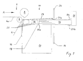
- FIGS. 1 and 2 is schematically shown by a paper processing plant of the example, as viewed in the process direction according to arrow A, downstream end portion of a conveyor 2 with an endless conveyor belt 4, which is deflected at its downstream end via a guide roller.
- Abeller 8 rotatably mounted which is referred to briefly as a racket and its axis of rotation, not shown in the figures, is parallel to the axis of rotation of the guide roller 6.
- Fig. 2 in which the racket 8 is omitted, can be seen that the conveyor 2 in the illustrated embodiment has a plurality of adjacent conveyor belts 4, which are deflected together via the guide roller 6.
- the upper run 4a of the conveyor belts 4 forms a plane not shown in the figures, in which the sheets are transported, so that that level can also be referred to as a transport plane.
- a downstream collecting station 10 which is also referred to as a stacking device or stack tray.
- the sheets brought up by the conveyor 2 are transported in the direction of the arrow A, which thus indicates not only the process direction but also the transport direction of the sheets.
- the collection station 10 is also part of the paper processing plant and serves as a stacking tray to form stacks from the supplied from the conveyor 2 sheets.
- rollers which consist of a wound continuous sheet of sheet paper, which is unwound from the corresponding roll for subsequent processing.
- the subsequent processing steps include in such a system a longitudinal and transverse cutting of the sheet web to sheets of a predetermined size, including corresponding longitudinal cutting and cross cutting stations are provided.
- the finished sheets are stacked at the end of the processing process, for which purpose the collection station 10 already mentioned above is provided.
- the cut sheets can be placed on their way to collecting station 10 in an overlapping, scaly arrangement, which take place for example in the conveyor 2 or for which alternatively a separate overlapping station can be provided.
- a corresponding printing station should be provided, which preferably lies upstream of the longitudinal and transverse cutting stations.
- the collection station 10 After forming the finished stack, which may be so-called. Clips, giant, book blocks or simple stack of sheets, the stack from the collection station 10 are removed and fed to another processing. Therefore, the collection station 10 also has the function of a transfer station.
- the collecting station 10 has a stack forming area 12, which forms a collecting box.
- the stack forming area 12 has a corresponding number of adjacent individual collection boxes, which is not shown in the figures.
- the stack formation area 12 In the transport direction according to arrow A forward is the stack formation area 12 limited by a front stop 14, which is also referred to as a front-end.
- the front stop 14 consists of a vertically arranged plate-shaped element which is movable in the vertical direction and thus arranged adjustable in its vertical height.
- the stack forming area 12 is limited at its rear side, ie on its in relation to the transport direction according to arrow A downstream side by a rear stop 16.
- the rear stop 16 consists of a plate-shaped element which is vertically aligned and stationary.
- the upper end of the rear stop 16 is in the illustrated embodiment, although adjacent to the guide roller 6 of the conveyor 2, but below the transport plane formed by the upper run 4a of the conveyor belt 4, so that the conveyed from the conveyor 2 sheets on the rear stop 16 away in the stack formation area 12 of the collection station 10 can get.
- the stack-up area 12 which is open at the top, is delimited by a base 18, which simultaneously forms the upper side of a box-shaped housing 20 in the exemplary embodiment shown.
- a plurality of pins 22 is mounted, which are aligned vertically and are guided by not shown corresponding openings in the bottom 18 and extend upward in the direction of the upper run 4a of the conveyor belt 4 spanned transport plane.
- the pins 22 are arranged in the illustrated embodiment with respect to the transport direction according to arrow A both behind each other and next to each other in the manner of a matrix substantially over the entire bottom 18 of the stack forming area 12.
- the pins 22 serve to receive the incoming from the conveyor 2 sheets and thus take over a support function for storing the sheets for the formation of a stack. Therefore, the pins 22 may also be referred to as support elements. While the pins 22 shown in the figures consist only of a rod or pin-shaped body, it is for example alternative also conceivable to provide the pins with a relative to the rod or pin-shaped body wider, preferably flat, head or stamp to form a larger surface support for the sheets, which is not shown in the figures.
- the pins 22 are movably mounted in the vertical direction between an upper end position and a lower end position. In the upper end position, the pins 22 are extended furthest. In the Fig. 1 visible pins 22 are in their upper end position. In the lower end position, however, the pins are retracted. In the embodiments shown in the figures, the pins 22 are in its lower end position with its upper front end or head at height and in alignment with the bottom 18 and thus substantially completely withdrawn into the housing 20 down or disappeared in this , In particular, when the pins 22 are movably mounted in the housing 20 so that they are retracted into a lower position below the bottom 18 in the housing 20 and thus below the bottom 18, the effective lower end position is alternatively formed by the bottom 18.
- the collection station 10 further includes a separating finger 24 to keep separated after forming a finished stack, the subsequently brought up by the conveyor 2 sheets of that stack.
- the separating finger 24 is disposed on the upstream with respect to the transport direction according to arrow A, front side of the stack formation area 12 above the front stop 14 and is in alignment with this.
- the separating finger 24 is movably supported on a holder, not shown.
- the collection station 10 shown also has a pair of pliers 26, which, viewed in the transport direction according to arrow A, is arranged downstream of the stack formation area 12. Also, the pliers 26 is movably supported on a bracket, also not shown in the figures.
- Fig. 1 shows an operating state in which of the conveyor 2, a sheet 28 has been promoted in the stack forming area 12 of the collecting station 10 and with its, viewed in the direction of transport according to arrow A, upstream, trailing rear portion rests on the fully extended pins 22 and with its downstream in the transport direction according to arrow A, leading or front edge of the substantially horizontally oriented and extending in the direction of the stacking region 12 extending finger portion 24a of the separating finger 24 is under attack. Further leaves Fig. 1 recognize a finished stack 30, which has already been pulled out of the pliers 26 to a greater extent from the stack formation area 12 of the collection station 10 and rests on the floor 18 only with its upstream portion. As in Fig.
- the pliers 26 in the illustrated embodiment, an upper jaw 26a and a lower jaw 26b, between which, as viewed in the transport direction according to arrow A, upstream edge of the finished stack 30 is clamped, whereby the pliers 26 this edge of the stack 30 engages and in the illustrated embodiment in the direction corresponding to the transport direction according to arrow A from the stack formation area 12 of the collection station 10 pulls out.
- Fig. 2 In the area where the stack 30 rests with its upstream portion still on the floor 18, the pins 22 are fully retracted, which in Fig. 2 is indicated by a schematic dashed representation of the pins in the region of the stack 30.
- the fact that the pins 22 are extended in the region of the stack formation area 12 between the stack 30 and the conveyor 2 is also indicated by solid circles in FIG Fig. 2 indicated, in which, however, the representation of the already above arch 28 ( Fig. 1 ) has been omitted for the sake of clarity.
- a lifting device For the movement of the pins 22 between its upper end position and its lower end position, a lifting device may be provided which is disposed within the housing 20 and not shown in the figures. Such a lifting device can preferably be operated by an electric motor, electromagnetically, pneumatically or hydraulically in order to extend or lower or retract the pins 22.
- the lifting device is preferably controlled by a control device such that the pins 22 are lowered during the formation of the stack 30 by continuously brought-up sheets 28 such that the top of the gradually growing stack 30 quasi stationary remains in approximately the same horizontal plane and preferably slightly below the is located from the upper strand 4a of the conveyor belt 4 plane.
- the controller should control the lifting device so that the resulting gap behind the stack 30 immediately by a As fast as possible movement of the pins 22 is filled from its lower end position to the upper end position.
- This latter measure is particularly advantageous so that the new sheets 28 for the next batch immediately experienced a support by the pins 22 and thereby largely parallel - initially with the participation of the separating finger 24 - come to rest.
- the aforementioned control device is preferably also housed in the housing 20.
- the lifting device and the control device are preferably designed so that the pins 22 can be adjusted individually or at least in rows individually.
- the pins 22 Regardless of whether the resilient mounting is actively realized by means of the previously described lifting device or passive by a resilient bias, at least for a termination of operation, the pins 22 also drive due to their own weight in the lower end position by the lifting device or the resilient bias is deactivated.
- Fig. 3 are in the same schematic side view as in Fig. 1 show nine different operating states (a) to (i) to illustrate the function of the arrangement described above.
- Fig. 3a shows an operating state with an already finished stack 30, which is still in the stacking area of the collection station 10, but with its front edge is already gripped by the pliers 26. So that the pliers 26 can pull out the stack 30 from the stack formation area of the collecting station 10, the front stop 14 has moved into a lower position, as Fig. 3a also shows. The separating finger 24 is moved to a lower position just above the stack 30 to engage under the next delivered sheet 28 of the conveyor belts 4 after its arrival in the stacking area of the collecting station 10, as in Fig. 3b is shown. It shows Fig.
- the front stop 14 is moved to its lower rest position and the separating finger 24 in its lower operating position just above the stack 30 and the pliers 26 brought into engagement with the stack 30 so that now the operating state of Fig. 3a is reached again.
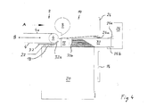
- Fig. 4 shows a modified embodiment, compared to the in the FIGS. 1 and 2 illustrated embodiment to a so-called.
- Hold-down 32 is extended.
- This holding-down device 32 is arranged in the upstream of the stacking region 12 of the collecting station 10 in relation to the transport direction according to arrow A and consists in the illustrated embodiment of a substantially horizontally lying plate-shaped element, with respect to the transport direction according to arrow A downstream end 32a is inclined upward and thus points to the upper position of the pins 22.
- the hold-down 32 is retractably supported from the upstream side of the stack forming area 12 into the stack forming area 12 and configured to hold the pins 22 located thereon in a lowered position, such as Fig. 4 can also recognize.
- a blank holder 32 is advantageous if the conveyor 2 is provided with a flexible format adjustment, whereby at least the arrangement of the conveyor belts 4, the guide roller 6 and the racket 8 in a substantially horizontal direction according to double arrow B parallel to the transport direction of Arches 28 reciprocally adjustable according to arrow A.
- Fig. 4 a state is shown in which the arrangement of the conveyor belts 4, the guide roller 6 and the racket 8 in the adjacent, with respect to the transporting direction A upstream portion of the stacking region 10 of the collecting station 2 is retracted. So that the pins 22 do not disturb in this section, they must be kept there in a lowered position, which is taken over by the hold-down 32, thereby making room for the flexible format adjustment of the conveyor 2.
- the upwardly inclined end portion 32a of the blank holder 32 may be formed so that it comes into contact with the pins 22 during the adjustment of the blank holder 32 in the direction corresponding to the transport direction according to arrow A and presses them down.
- Fig. 5 it is the same top view as at Fig. 2 , wherein additionally two side stops 34 are provided for lateral format adjustment or width adjustment.
- These side stops 34 form lateral and consist in the illustrated embodiment of upright walls or sheets.
- the side stops 34 are arranged on the bottom 18 of the stack formation area 12 in the direction of the double arrow C transversely to the transport direction according to arrow A reciprocally displaceable.
- the underside of the side stops 34 is formed so that they are in the Hold their area in their respective position pins 22 in its lower position, which in Fig. 5 is indicated by a schematic dashed representation of those pins 22.
- the bottom 18 of the stack forming area 12 becomes flexible in terms of format, since the lateral stops 34 simply cover the unnecessary pins.
- the lateral stops 34 are preferably subjected to vibratory movements by drives which are not shown, which is advantageous for the formation of straight edges on the stack 30. In this context, it is additionally conceivable to offset at least the pins 30 carrying the stack 30 in comparable vibration movements.
Landscapes
- Engineering & Computer Science (AREA)
- Mechanical Engineering (AREA)
- Pile Receivers (AREA)
- Stacking Of Articles And Auxiliary Devices (AREA)
- Sheets, Magazines, And Separation Thereof (AREA)
Applications Claiming Priority (1)
| Application Number | Priority Date | Filing Date | Title |
|---|---|---|---|
| DE201110006482 DE102011006482A1 (de) | 2011-03-31 | 2011-03-31 | Stapelbildungsvorrichtung |
Publications (3)
| Publication Number | Publication Date |
|---|---|
| EP2505536A2 true EP2505536A2 (fr) | 2012-10-03 |
| EP2505536A3 EP2505536A3 (fr) | 2013-03-06 |
| EP2505536B1 EP2505536B1 (fr) | 2014-08-27 |
Family
ID=45954423
Family Applications (1)
| Application Number | Title | Priority Date | Filing Date |
|---|---|---|---|
| EP20120161717 Active EP2505536B1 (fr) | 2011-03-31 | 2012-03-28 | Dispositif de formation de piles |
Country Status (8)
| Country | Link |
|---|---|
| US (1) | US8991810B2 (fr) |
| EP (1) | EP2505536B1 (fr) |
| JP (1) | JP2012214297A (fr) |
| CN (1) | CN102730468A (fr) |
| BR (1) | BR102012007346A2 (fr) |
| DE (1) | DE102011006482A1 (fr) |
| ES (1) | ES2516824T3 (fr) |
| IN (1) | IN2012DE00978A (fr) |
Cited By (2)
| Publication number | Priority date | Publication date | Assignee | Title |
|---|---|---|---|---|
| CN104385159A (zh) * | 2014-11-24 | 2015-03-04 | 盐城市华森机械有限公司 | 多层砂纸自动冲裁成型设备 |
| US9221628B2 (en) | 2011-12-07 | 2015-12-29 | Ferg Ag | Device and method for composing two-dimensional products, in particular printed products |
Families Citing this family (2)
| Publication number | Priority date | Publication date | Assignee | Title |
|---|---|---|---|---|
| CN109179040B (zh) * | 2018-09-21 | 2020-06-02 | 南京理工技术转移中心有限公司 | 一种打印机的出纸收集装置 |
| CN112875394B (zh) * | 2021-02-03 | 2022-05-27 | 嘉善精田精密机械股份有限公司 | 一种棉柔巾生产用分离输送装置 |
Family Cites Families (17)
| Publication number | Priority date | Publication date | Assignee | Title |
|---|---|---|---|---|
| FR1491453A (fr) * | 1966-06-28 | 1967-08-11 | Wean Damiron | Dispositif d'empilage de tôles |
| US4183704A (en) * | 1976-10-29 | 1980-01-15 | Rima Enterprises | Compensating stacker for printed signatures |
| US4136864A (en) * | 1977-06-16 | 1979-01-30 | Westvaco Corporation | Sheet stacking device |
| DE2808948A1 (de) * | 1978-03-02 | 1979-09-13 | Will E C H Gmbh & Co | Vorrichtung zum aufeinanderschichten von lagen aus papierbogen |
| DE3024112A1 (de) * | 1980-06-27 | 1982-02-04 | Pfaff Industriemaschinen Gmbh, 6750 Kaiserslautern | Einrichtung zum handhaben von stapeln flexibler gegenstaende, z.b. zeitschriften |
| DE3046107C2 (de) * | 1980-12-06 | 1982-11-18 | Bielomatik Leuze Gmbh + Co, 7442 Neuffen | Vorrichtung zum Ablegen von Bogen zu einem Stapel |
| JPS5842554A (ja) * | 1981-09-01 | 1983-03-12 | Fuji Xerox Co Ltd | 複写機の用紙サイズ別収容装置 |
| JPS58135053A (ja) * | 1982-02-02 | 1983-08-11 | Mitsubishi Heavy Ind Ltd | 板紙計数集積装置 |
| DE3614884A1 (de) * | 1986-05-02 | 1987-11-05 | Will E C H Gmbh & Co | Stapelvorrichtung |
| JPH02100924A (ja) * | 1988-10-08 | 1990-04-12 | Nippon Oil & Fats Co Ltd | 小物品の処理方法及び装置 |
| US5425565A (en) * | 1993-08-12 | 1995-06-20 | Tension Envelope Corporation | Multiple envelope gripping and transfer apparatus and method |
| GB9718467D0 (en) * | 1997-09-02 | 1997-11-05 | Ncr Int Inc | An apparatus for stacking sheets |
| DE19849859A1 (de) * | 1998-10-29 | 2000-05-04 | Will E C H Gmbh & Co | Vorrichtung zum Bilden und Abfördern von Bogenstapeln |
| JP2001089005A (ja) * | 1999-09-17 | 2001-04-03 | Minolta Co Ltd | 用紙積載装置 |
| US6679491B2 (en) * | 2001-09-17 | 2004-01-20 | Siemens Aktiengesellschaft | Mail piece feeder control system and method |
| US7866936B2 (en) * | 2007-05-01 | 2011-01-11 | Northrop Grumman Systems Corporation | System and method for transferring mail between containers |
| US9013682B2 (en) * | 2007-06-21 | 2015-04-21 | Asml Netherlands B.V. | Clamping device and object loading method |
-
2011
- 2011-03-31 DE DE201110006482 patent/DE102011006482A1/de not_active Withdrawn
-
2012
- 2012-03-28 EP EP20120161717 patent/EP2505536B1/fr active Active
- 2012-03-28 ES ES12161717.9T patent/ES2516824T3/es active Active
- 2012-03-30 IN IN978DE2012 patent/IN2012DE00978A/en unknown
- 2012-03-30 CN CN2012101572333A patent/CN102730468A/zh active Pending
- 2012-03-30 BR BR102012007346A patent/BR102012007346A2/pt not_active Application Discontinuation
- 2012-03-30 JP JP2012079297A patent/JP2012214297A/ja active Pending
- 2012-03-30 US US13/435,495 patent/US8991810B2/en active Active
Non-Patent Citations (1)
| Title |
|---|
| None |
Cited By (4)
| Publication number | Priority date | Publication date | Assignee | Title |
|---|---|---|---|---|
| US9221628B2 (en) | 2011-12-07 | 2015-12-29 | Ferg Ag | Device and method for composing two-dimensional products, in particular printed products |
| EP2602220B1 (fr) * | 2011-12-07 | 2016-10-12 | Ferag AG | Dispositif et procédé d'assemblage de produits plats, en particulier de produits d'imprimerie |
| CN104385159A (zh) * | 2014-11-24 | 2015-03-04 | 盐城市华森机械有限公司 | 多层砂纸自动冲裁成型设备 |
| CN104385159B (zh) * | 2014-11-24 | 2017-01-18 | 盐城市华森机械有限公司 | 多层砂纸自动冲裁成型设备 |
Also Published As
| Publication number | Publication date |
|---|---|
| EP2505536A3 (fr) | 2013-03-06 |
| US20120274018A1 (en) | 2012-11-01 |
| CN102730468A (zh) | 2012-10-17 |
| JP2012214297A (ja) | 2012-11-08 |
| ES2516824T3 (es) | 2014-10-31 |
| EP2505536B1 (fr) | 2014-08-27 |
| BR102012007346A2 (pt) | 2013-06-04 |
| IN2012DE00978A (fr) | 2015-09-11 |
| DE102011006482A1 (de) | 2012-10-04 |
| US8991810B2 (en) | 2015-03-31 |
Similar Documents
| Publication | Publication Date | Title |
|---|---|---|
| DE3500766C2 (de) | Vorrichtung zum Herstellen einzelner, aus einer zickzackförmig gefalteten Materialbahn bestehender Stapel | |
| EP1870361B1 (fr) | Procédé et dispositif destinés à la formation de piles de pièces plates | |
| EP0359920B1 (fr) | Dispositif pour empiler automatiquement des objets plats | |
| EP2505536B1 (fr) | Dispositif de formation de piles | |
| EP0257247B1 (fr) | Procédé et dispositif pour enlever des bloc-notes d'une pile | |
| DE102005002532A1 (de) | Vorrichtung und Verfahren zum automatisierten und zeitgleichen Bereitstellen und Wechseln von mindestens zwei Rollen aus Papierbahnen oder dergleichen für einen nachgeordneten Formatschneider | |
| EP3241791B1 (fr) | Procédé de fabrication d'empilements de feuilles | |
| EP0591099B1 (fr) | Procédé et dispositif pour fabriquer des piles de produits en papier liées | |
| DE102008024599A1 (de) | Vorrichtung zur Bildung von Stapelpaketen | |
| DE3514487C2 (fr) | ||
| EP1961660A1 (fr) | Dispositif et procédé destinés à l'emballage d'objets empilables, en particulier de résultats d'impression | |
| DE102009045319B4 (de) | Formateinstellvorrichtung | |
| EP3590850B1 (fr) | Procédé et dispositif d'empilement et d'emballage de produits pliés | |
| EP2323938B1 (fr) | Dispositif de collecte et de transport d'empilements formés de couches de feuilles | |
| DE102019128977A1 (de) | Bogenbearbeitungsmaschine mit zumindest einer Bogenablageeinrichtung und Verfahren zur Bogenablage | |
| EP2436623B1 (fr) | Procédé et dispositif pour enlever une rangée de piles | |
| DE102010014336A1 (de) | Vorrichtung und Verfahren zum Stapeln von Profilteilen | |
| DE102009022249B4 (de) | Übergabevorrichtung zur Übergabe eines durch mehrere Blattlagen gebildeten Stapels | |
| DE3934660A1 (de) | Verfahren und vorrichtung zum herstellen von zigarren o.dgl. | |
| EP1522509B1 (fr) | Appareil d'empilage de produits plats | |
| DE3904720A1 (de) | Verfahren zum zufuehren eines geschlossenen blattstapels | |
| DE10347165B4 (de) | Vorrichtung zum Stapeln von flachen Produkten | |
| EP3907163A1 (fr) | Applicateur pour empilements de supports plats | |
| DE102012206856A1 (de) | Vorrichtung zum Transport von Stapeln aus Flachteilen | |
| EP2657161B1 (fr) | Procédé et dispositif d'alimentation automatique de piles de feuilles individuelles provenant d'une presse dans une machine de reliure par collage |
Legal Events
| Date | Code | Title | Description |
|---|---|---|---|
| PUAI | Public reference made under article 153(3) epc to a published international application that has entered the european phase |
Free format text: ORIGINAL CODE: 0009012 |
|
| AK | Designated contracting states |
Kind code of ref document: A2 Designated state(s): AL AT BE BG CH CY CZ DE DK EE ES FI FR GB GR HR HU IE IS IT LI LT LU LV MC MK MT NL NO PL PT RO RS SE SI SK SM TR |
|
| AX | Request for extension of the european patent |
Extension state: BA ME |
|
| PUAL | Search report despatched |
Free format text: ORIGINAL CODE: 0009013 |
|
| AK | Designated contracting states |
Kind code of ref document: A3 Designated state(s): AL AT BE BG CH CY CZ DE DK EE ES FI FR GB GR HR HU IE IS IT LI LT LU LV MC MK MT NL NO PL PT RO RS SE SI SK SM TR |
|
| AX | Request for extension of the european patent |
Extension state: BA ME |
|
| RIC1 | Information provided on ipc code assigned before grant |
Ipc: B65H 31/32 20060101ALI20130125BHEP Ipc: B65H 31/20 20060101ALI20130125BHEP Ipc: B65H 31/30 20060101ALI20130125BHEP Ipc: B65H 31/10 20060101AFI20130125BHEP |
|
| 17P | Request for examination filed |
Effective date: 20130906 |
|
| RBV | Designated contracting states (corrected) |
Designated state(s): AL AT BE BG CH CY CZ DE DK EE ES FI FR GB GR HR HU IE IS IT LI LT LU LV MC MK MT NL NO PL PT RO RS SE SI SK SM TR |
|
| GRAP | Despatch of communication of intention to grant a patent |
Free format text: ORIGINAL CODE: EPIDOSNIGR1 |
|
| INTG | Intention to grant announced |
Effective date: 20140312 |
|
| GRAS | Grant fee paid |
Free format text: ORIGINAL CODE: EPIDOSNIGR3 |
|
| GRAA | (expected) grant |
Free format text: ORIGINAL CODE: 0009210 |
|
| AK | Designated contracting states |
Kind code of ref document: B1 Designated state(s): AL AT BE BG CH CY CZ DE DK EE ES FI FR GB GR HR HU IE IS IT LI LT LU LV MC MK MT NL NO PL PT RO RS SE SI SK SM TR |
|
| REG | Reference to a national code |
Ref country code: GB Ref legal event code: FG4D Free format text: NOT ENGLISH |
|
| REG | Reference to a national code |
Ref country code: CH Ref legal event code: EP |
|
| REG | Reference to a national code |
Ref country code: AT Ref legal event code: REF Ref document number: 684414 Country of ref document: AT Kind code of ref document: T Effective date: 20140915 |
|
| REG | Reference to a national code |
Ref country code: IE Ref legal event code: FG4D Free format text: LANGUAGE OF EP DOCUMENT: GERMAN |
|
| REG | Reference to a national code |
Ref country code: DE Ref legal event code: R096 Ref document number: 502012001160 Country of ref document: DE Effective date: 20141009 |
|
| REG | Reference to a national code |
Ref country code: ES Ref legal event code: FG2A Ref document number: 2516824 Country of ref document: ES Kind code of ref document: T3 Effective date: 20141031 |
|
| REG | Reference to a national code |
Ref country code: LT Ref legal event code: MG4D |
|
| REG | Reference to a national code |
Ref country code: NL Ref legal event code: VDEP Effective date: 20140827 |
|
| PG25 | Lapsed in a contracting state [announced via postgrant information from national office to epo] |
Ref country code: PT Free format text: LAPSE BECAUSE OF FAILURE TO SUBMIT A TRANSLATION OF THE DESCRIPTION OR TO PAY THE FEE WITHIN THE PRESCRIBED TIME-LIMIT Effective date: 20141229 Ref country code: BG Free format text: LAPSE BECAUSE OF FAILURE TO SUBMIT A TRANSLATION OF THE DESCRIPTION OR TO PAY THE FEE WITHIN THE PRESCRIBED TIME-LIMIT Effective date: 20141127 Ref country code: LT Free format text: LAPSE BECAUSE OF FAILURE TO SUBMIT A TRANSLATION OF THE DESCRIPTION OR TO PAY THE FEE WITHIN THE PRESCRIBED TIME-LIMIT Effective date: 20140827 Ref country code: NO Free format text: LAPSE BECAUSE OF FAILURE TO SUBMIT A TRANSLATION OF THE DESCRIPTION OR TO PAY THE FEE WITHIN THE PRESCRIBED TIME-LIMIT Effective date: 20141127 Ref country code: GR Free format text: LAPSE BECAUSE OF FAILURE TO SUBMIT A TRANSLATION OF THE DESCRIPTION OR TO PAY THE FEE WITHIN THE PRESCRIBED TIME-LIMIT Effective date: 20141128 Ref country code: FI Free format text: LAPSE BECAUSE OF FAILURE TO SUBMIT A TRANSLATION OF THE DESCRIPTION OR TO PAY THE FEE WITHIN THE PRESCRIBED TIME-LIMIT Effective date: 20140827 Ref country code: SE Free format text: LAPSE BECAUSE OF FAILURE TO SUBMIT A TRANSLATION OF THE DESCRIPTION OR TO PAY THE FEE WITHIN THE PRESCRIBED TIME-LIMIT Effective date: 20140827 |
|
| PG25 | Lapsed in a contracting state [announced via postgrant information from national office to epo] |
Ref country code: HR Free format text: LAPSE BECAUSE OF FAILURE TO SUBMIT A TRANSLATION OF THE DESCRIPTION OR TO PAY THE FEE WITHIN THE PRESCRIBED TIME-LIMIT Effective date: 20140827 Ref country code: IS Free format text: LAPSE BECAUSE OF FAILURE TO SUBMIT A TRANSLATION OF THE DESCRIPTION OR TO PAY THE FEE WITHIN THE PRESCRIBED TIME-LIMIT Effective date: 20141227 Ref country code: LV Free format text: LAPSE BECAUSE OF FAILURE TO SUBMIT A TRANSLATION OF THE DESCRIPTION OR TO PAY THE FEE WITHIN THE PRESCRIBED TIME-LIMIT Effective date: 20140827 Ref country code: CY Free format text: LAPSE BECAUSE OF FAILURE TO SUBMIT A TRANSLATION OF THE DESCRIPTION OR TO PAY THE FEE WITHIN THE PRESCRIBED TIME-LIMIT Effective date: 20140827 Ref country code: RS Free format text: LAPSE BECAUSE OF FAILURE TO SUBMIT A TRANSLATION OF THE DESCRIPTION OR TO PAY THE FEE WITHIN THE PRESCRIBED TIME-LIMIT Effective date: 20140827 |
|
| PG25 | Lapsed in a contracting state [announced via postgrant information from national office to epo] |
Ref country code: NL Free format text: LAPSE BECAUSE OF FAILURE TO SUBMIT A TRANSLATION OF THE DESCRIPTION OR TO PAY THE FEE WITHIN THE PRESCRIBED TIME-LIMIT Effective date: 20140827 |
|
| PG25 | Lapsed in a contracting state [announced via postgrant information from national office to epo] |
Ref country code: EE Free format text: LAPSE BECAUSE OF FAILURE TO SUBMIT A TRANSLATION OF THE DESCRIPTION OR TO PAY THE FEE WITHIN THE PRESCRIBED TIME-LIMIT Effective date: 20140827 Ref country code: DK Free format text: LAPSE BECAUSE OF FAILURE TO SUBMIT A TRANSLATION OF THE DESCRIPTION OR TO PAY THE FEE WITHIN THE PRESCRIBED TIME-LIMIT Effective date: 20140827 Ref country code: CZ Free format text: LAPSE BECAUSE OF FAILURE TO SUBMIT A TRANSLATION OF THE DESCRIPTION OR TO PAY THE FEE WITHIN THE PRESCRIBED TIME-LIMIT Effective date: 20140827 Ref country code: RO Free format text: LAPSE BECAUSE OF FAILURE TO SUBMIT A TRANSLATION OF THE DESCRIPTION OR TO PAY THE FEE WITHIN THE PRESCRIBED TIME-LIMIT Effective date: 20140827 Ref country code: SK Free format text: LAPSE BECAUSE OF FAILURE TO SUBMIT A TRANSLATION OF THE DESCRIPTION OR TO PAY THE FEE WITHIN THE PRESCRIBED TIME-LIMIT Effective date: 20140827 Ref country code: IT Free format text: LAPSE BECAUSE OF FAILURE TO SUBMIT A TRANSLATION OF THE DESCRIPTION OR TO PAY THE FEE WITHIN THE PRESCRIBED TIME-LIMIT Effective date: 20140827 |
|
| REG | Reference to a national code |
Ref country code: DE Ref legal event code: R097 Ref document number: 502012001160 Country of ref document: DE |
|
| PG25 | Lapsed in a contracting state [announced via postgrant information from national office to epo] |
Ref country code: PL Free format text: LAPSE BECAUSE OF FAILURE TO SUBMIT A TRANSLATION OF THE DESCRIPTION OR TO PAY THE FEE WITHIN THE PRESCRIBED TIME-LIMIT Effective date: 20140827 |
|
| PLBE | No opposition filed within time limit |
Free format text: ORIGINAL CODE: 0009261 |
|
| STAA | Information on the status of an ep patent application or granted ep patent |
Free format text: STATUS: NO OPPOSITION FILED WITHIN TIME LIMIT |
|
| 26N | No opposition filed |
Effective date: 20150528 |
|
| PG25 | Lapsed in a contracting state [announced via postgrant information from national office to epo] |
Ref country code: MC Free format text: LAPSE BECAUSE OF FAILURE TO SUBMIT A TRANSLATION OF THE DESCRIPTION OR TO PAY THE FEE WITHIN THE PRESCRIBED TIME-LIMIT Effective date: 20140827 Ref country code: LU Free format text: LAPSE BECAUSE OF FAILURE TO SUBMIT A TRANSLATION OF THE DESCRIPTION OR TO PAY THE FEE WITHIN THE PRESCRIBED TIME-LIMIT Effective date: 20150328 |
|
| REG | Reference to a national code |
Ref country code: CH Ref legal event code: PL |
|
| PG25 | Lapsed in a contracting state [announced via postgrant information from national office to epo] |
Ref country code: SI Free format text: LAPSE BECAUSE OF FAILURE TO SUBMIT A TRANSLATION OF THE DESCRIPTION OR TO PAY THE FEE WITHIN THE PRESCRIBED TIME-LIMIT Effective date: 20140827 |
|
| REG | Reference to a national code |
Ref country code: FR Ref legal event code: ST Effective date: 20151130 |
|
| REG | Reference to a national code |
Ref country code: IE Ref legal event code: MM4A |
|
| PG25 | Lapsed in a contracting state [announced via postgrant information from national office to epo] |
Ref country code: IE Free format text: LAPSE BECAUSE OF NON-PAYMENT OF DUE FEES Effective date: 20150328 Ref country code: CH Free format text: LAPSE BECAUSE OF NON-PAYMENT OF DUE FEES Effective date: 20150331 Ref country code: LI Free format text: LAPSE BECAUSE OF NON-PAYMENT OF DUE FEES Effective date: 20150331 |
|
| PG25 | Lapsed in a contracting state [announced via postgrant information from national office to epo] |
Ref country code: FR Free format text: LAPSE BECAUSE OF NON-PAYMENT OF DUE FEES Effective date: 20150331 |
|
| GBPC | Gb: european patent ceased through non-payment of renewal fee |
Effective date: 20160328 |
|
| PG25 | Lapsed in a contracting state [announced via postgrant information from national office to epo] |
Ref country code: MT Free format text: LAPSE BECAUSE OF FAILURE TO SUBMIT A TRANSLATION OF THE DESCRIPTION OR TO PAY THE FEE WITHIN THE PRESCRIBED TIME-LIMIT Effective date: 20140827 |
|
| PG25 | Lapsed in a contracting state [announced via postgrant information from national office to epo] |
Ref country code: GB Free format text: LAPSE BECAUSE OF NON-PAYMENT OF DUE FEES Effective date: 20160328 |
|
| PG25 | Lapsed in a contracting state [announced via postgrant information from national office to epo] |
Ref country code: HU Free format text: LAPSE BECAUSE OF FAILURE TO SUBMIT A TRANSLATION OF THE DESCRIPTION OR TO PAY THE FEE WITHIN THE PRESCRIBED TIME-LIMIT; INVALID AB INITIO Effective date: 20120328 Ref country code: SM Free format text: LAPSE BECAUSE OF FAILURE TO SUBMIT A TRANSLATION OF THE DESCRIPTION OR TO PAY THE FEE WITHIN THE PRESCRIBED TIME-LIMIT Effective date: 20140827 |
|
| PG25 | Lapsed in a contracting state [announced via postgrant information from national office to epo] |
Ref country code: BE Free format text: LAPSE BECAUSE OF NON-PAYMENT OF DUE FEES Effective date: 20150331 |
|
| PG25 | Lapsed in a contracting state [announced via postgrant information from national office to epo] |
Ref country code: TR Free format text: LAPSE BECAUSE OF FAILURE TO SUBMIT A TRANSLATION OF THE DESCRIPTION OR TO PAY THE FEE WITHIN THE PRESCRIBED TIME-LIMIT Effective date: 20140827 |
|
| REG | Reference to a national code |
Ref country code: DE Ref legal event code: R082 Ref document number: 502012001160 Country of ref document: DE Representative=s name: VON ROHR PATENTANWAELTE PARTNERSCHAFT MBB, DE |
|
| REG | Reference to a national code |
Ref country code: AT Ref legal event code: MM01 Ref document number: 684414 Country of ref document: AT Kind code of ref document: T Effective date: 20170328 |
|
| PG25 | Lapsed in a contracting state [announced via postgrant information from national office to epo] |
Ref country code: MK Free format text: LAPSE BECAUSE OF FAILURE TO SUBMIT A TRANSLATION OF THE DESCRIPTION OR TO PAY THE FEE WITHIN THE PRESCRIBED TIME-LIMIT Effective date: 20140827 |
|
| PG25 | Lapsed in a contracting state [announced via postgrant information from national office to epo] |
Ref country code: AT Free format text: LAPSE BECAUSE OF NON-PAYMENT OF DUE FEES Effective date: 20170328 |
|
| PG25 | Lapsed in a contracting state [announced via postgrant information from national office to epo] |
Ref country code: AL Free format text: LAPSE BECAUSE OF FAILURE TO SUBMIT A TRANSLATION OF THE DESCRIPTION OR TO PAY THE FEE WITHIN THE PRESCRIBED TIME-LIMIT Effective date: 20140827 |
|
| REG | Reference to a national code |
Ref country code: DE Ref legal event code: R082 Ref document number: 502012001160 Country of ref document: DE Representative=s name: VON ROHR PATENTANWAELTE PARTNERSCHAFT MBB, DE Ref country code: DE Ref legal event code: R081 Ref document number: 502012001160 Country of ref document: DE Owner name: BW PAPERSYSTEMS STUTTGART GMBH, DE Free format text: FORMER OWNER: KUGLER-WOMAKO GMBH, 72622 NUERTINGEN, DE |
|
| PGFP | Annual fee paid to national office [announced via postgrant information from national office to epo] |
Ref country code: DE Payment date: 20220323 Year of fee payment: 11 |
|
| PGFP | Annual fee paid to national office [announced via postgrant information from national office to epo] |
Ref country code: ES Payment date: 20220527 Year of fee payment: 11 |
|
| REG | Reference to a national code |
Ref country code: DE Ref legal event code: R119 Ref document number: 502012001160 Country of ref document: DE |
|
| PG25 | Lapsed in a contracting state [announced via postgrant information from national office to epo] |
Ref country code: DE Free format text: LAPSE BECAUSE OF NON-PAYMENT OF DUE FEES Effective date: 20231003 |