EP2504611B1 - Betätigungsvorrichtung für gehäuse- oder gehäuselose armaturen - Google Patents
Betätigungsvorrichtung für gehäuse- oder gehäuselose armaturen Download PDFInfo
- Publication number
- EP2504611B1 EP2504611B1 EP20100781440 EP10781440A EP2504611B1 EP 2504611 B1 EP2504611 B1 EP 2504611B1 EP 20100781440 EP20100781440 EP 20100781440 EP 10781440 A EP10781440 A EP 10781440A EP 2504611 B1 EP2504611 B1 EP 2504611B1
- Authority
- EP
- European Patent Office
- Prior art keywords
- actuating device
- servo motor
- gear mechanism
- drive
- measuring device
- Prior art date
- Legal status (The legal status is an assumption and is not a legal conclusion. Google has not performed a legal analysis and makes no representation as to the accuracy of the status listed.)
- Not-in-force
Links
Images


Classifications
-
- F—MECHANICAL ENGINEERING; LIGHTING; HEATING; WEAPONS; BLASTING
- F16—ENGINEERING ELEMENTS AND UNITS; GENERAL MEASURES FOR PRODUCING AND MAINTAINING EFFECTIVE FUNCTIONING OF MACHINES OR INSTALLATIONS; THERMAL INSULATION IN GENERAL
- F16K—VALVES; TAPS; COCKS; ACTUATING-FLOATS; DEVICES FOR VENTING OR AERATING
- F16K31/00—Actuating devices; Operating means; Releasing devices
- F16K31/02—Actuating devices; Operating means; Releasing devices electric; magnetic
- F16K31/04—Actuating devices; Operating means; Releasing devices electric; magnetic using a motor
- F16K31/05—Actuating devices; Operating means; Releasing devices electric; magnetic using a motor specially adapted for operating hand-operated valves or for combined motor and hand operation
-
- Y—GENERAL TAGGING OF NEW TECHNOLOGICAL DEVELOPMENTS; GENERAL TAGGING OF CROSS-SECTIONAL TECHNOLOGIES SPANNING OVER SEVERAL SECTIONS OF THE IPC; TECHNICAL SUBJECTS COVERED BY FORMER USPC CROSS-REFERENCE ART COLLECTIONS [XRACs] AND DIGESTS
- Y10—TECHNICAL SUBJECTS COVERED BY FORMER USPC
- Y10T—TECHNICAL SUBJECTS COVERED BY FORMER US CLASSIFICATION
- Y10T137/00—Fluid handling
- Y10T137/8158—With indicator, register, recorder, alarm or inspection means
- Y10T137/8225—Position or extent of motion indicator
- Y10T137/8242—Electrical
Definitions
- the present invention relates to an actuator for housing or housing-less fittings, in particular for fittings for pipelines for the transport of liquid or gaseous medium, preferably for pipelines from a nominal diameter of DN 100 or channels, according to the preamble of claim 1.
- the actuating device according to the invention is particularly intended to drive rotating drive elements with a rotation means of more than 360 °.
- the DE 43 44 325 A1 describes an actuator. It includes an electric motor which drives a single-stage planetary gear via a gear gear and a motor-driven worm, the output of which is in communication with the valve. In addition, a further to be operated by handwheel, another screw is provided as an emergency gear, which is arranged opposite to the motor-driven worm on the planetary gear.
- a corresponding selection of the gears can be achieved by means of the single-stage planetary gear during engine operation, a translation of about 1: 2 and manual operation, a ratio of 1: 3 in the fast. For the total ratio in manual mode, a ratio of 12: 1 is given.
- the end positions of the drive are determined by dedicated limit switches.
- the DE 23 46 067 a drive device for driving translationally movable actuators, in particular valves with a planetary gear, which by means of a small, reversible electric drive motor with Endlagenabschalt adopted is operable.
- a spur gear is provided, which is also actuated by the drive motor, but also by means of a hand crank.
- FR 1328431 describes a Betsch whysvorrictung according to the preamble of claim 1.
- the object of the present invention is to provide a novel actuator for fittings of the generic type which avoids the above disadvantages.
- a servomotor is provided as the drive motor, which has a measuring device which determines the respective current position of the servo motor with respect to its initial position and outputs corresponding measured values
- a main memory is provided in which the measured values of the measuring device of the servomotor inscribed and an electronic control unit is provided which constantly reads out the measured values of the measuring device of the servo motor and performs a position control of the servomotor and thus of the actuating device on the basis of the measured values of the measuring device of the servomotor
- the transmission has a transmission ratio of at least 40: 1.
- the invention causes reduced dimensions of the actuator, on the other hand, a simplified construction is achieved, since it can be dispensed with mechanical limit switches and mechanical position indicators.
- the use of the servomotor makes it possible to realize the emergency drive with simple tools, such as a cordless screwdriver compared to the known from the prior art actuators. This is possible because the torque of a cordless screwdriver is of the order of magnitude similar to the torque of a servomotor.
- the actuating device is designed such that during operation of the emergency drive the servo motor is rotated.
- the invention thus has the advantage that no structurally complex decoupling between gearbox and servomotor must be provided. Further, the position determination upon actuation of the limp-home drive due to the rotation of the servomotor is still ensured.
- the emergency drive can initially be in a passive position and only becomes active when a coupling of the emergency drive with the drive shaft of the transmission has taken place.
- the transmission has at least a transmission ratio of 70: 1, particularly preferably 90: 1, on.
- Ideal is a range of 60: 1 - 80: 1, e.g. 70: 1st
- the torque of the servomotor is at most 30 Nm, preferably at most 20 Nm, more preferably at most 10 Nm.
- the servo motor has a torque of 3 - 8 Nm, most preferably 4 - 7 Nm.
- the measured values of the measuring device of the servomotor are expediently counting pulses in relation to the rotational movement of the servomotor, which can be evaluated for the current position determination and / or speed determination of the opening or closing movement of the valve and fed to the control.
- This makes it possible to make the opening or closing movement of the valve depending on the position of the same at different speeds, ie to program special speed characteristics.
- a slow opening speed can be provided which, when a certain position is reached, namely when the water pressure is no longer present or has been reduced, is increased.
- a measuring device that provides a clue to the counterforce acting on the servo motor.
- the measuring device can expediently be configured as a force-measuring device and / or as a measuring device detecting the current consumption of the servomotor. Both ensure each determination of a position point at which the force to be required by the servo motor exceeds a certain maximum value, namely, when the slider is in the sealing end position (closed position).
- the measuring device makes it possible to define increments or a profile of the force required by the servomotor over the movement distance of the fitting. For example, at the beginning of the opening process, the force to be provided by the servo motor has to be set higher, due to a "holding effect" of, for example, a closed valve that has not been operated for a long time.
- the measuring device also makes it possible to perform a load-dependent readjustment of the opening and / or closing speed.
- a particularly advantageous embodiment of the actuating device is characterized in that it has a self-locking.
- the fitting which may be a high weight device, will remain in its current position. This is due to the high gear ratio of the torque between the servomotor and the transmission.
- a servomotor has no caster. The aforementioned advantage is also set when switching off the servo motor at any point. In turn, there is no repressing the moving parts of the construction, which in turn no additional design measures are necessary to compensate for such repressions.
- the emergency drive can be operated in an advantageous manner, for example by means of a mains-independent cordless screwdriver.
- an emergency operation by hand drive for example, handwheel, screwdriver, etc.
- hand drive for example, handwheel, screwdriver, etc.
- the servomotor and the transmission are arranged along a common axis.
- the actuation of the emergency drive can in this case be provided at an angle, preferably right angle thereto.
- only one direction of force is realized thereby also with regard to the motor drive of the transmission, which is particularly advantageous for a compact arrangement.
- the transmission is a planetary gear, which is particularly suitable for the use of a servo motor.
- Reference numeral 1 in Fig. 1 denotes the actuator in its entirety. It comprises a gear 2, preferably a planetary gear.
- the output shaft 22 of the transmission 2 is connected to a valve, in this case with a slide 7, in connection.
- the slide 7 is intended to close or release a schematically indicated pipe 6 as needed.
- the slide 7 By actuation of the output shaft 22 of the transmission 2, the slide 7 by a in Fig. 1 not shown mechanism causes to move either down or up. It is expressly understood that the actuating device according to the present invention also for different types Fittings can be used.
- the actuator is intended primarily for valves in connection with pipelines from a nominal diameter DN 100.
- a run-flat drive 3 with an electric motor in connection, which is designed according to the present invention as a servomotor 4.
- This is an electric motor that forms a servo drive with a servo drive and is operated in a closed loop.
- a measuring device which detects the current position e.g. determines the covered angle of rotation with respect to an initial position of the rotor.
- a control unit 8 is provided for operation of the servomotor 4.
- the control unit 8 can also be an objective component of the servomotor 4. Alternatively, the control unit 8 may also be positioned at a location other than the location of the servomotor 4 and connected to the latter via a data line.
- Fig. 1 how out Fig. 1 it can be seen, are the servo motor 4 and the transmission 2 on a common longitudinal axis.
- auxiliary tool e.g. a cordless screwdriver 5
- an emergency operation of the slide 7 has to be done.
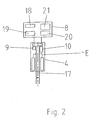
- the servo motor 4 has a counter 9 as a measuring device, which allows detection of the rotational movement of the rotor of the servomotor 4 or its shaft 17. For example, counter 9 generates 32,000 pulses during one revolution of the servo drive shaft. These counts are processed in the control unit 8 and over from the Fig. 2 not apparent logical functions further processed to position characteristics. The counts or position characteristics are stored in a memory 18 and read out constantly.
- the core of the controller is a processor 19. Also provided are an input field 20 and a display 21.
- a measuring device 10 may be provided, by means of which the force acting on the servomotor 4 can be determined and used in the context of the control.
- Fig. 3 shows in greater detail the connection region of servomotor 4 and gear 2.
- the shaft 17 of the servo motor 4 is directly connected to the drive shaft 16 of the transmission 2, without any translation takes place.
- In the area of this direct connection of the emergency drive is provided in the form of a right angle positioned drive shaft 11, at one end of a bevel gear 12 and at the other end a coupling possibility with a cordless screwdriver 5 is provided.
- the drive shaft 11 is biased by a spring 14 in a position outwardly.
- a bevel gear 13 is also positioned such that the two bevel gears 12 and 13 are at right angles to each other.
- this is moved in the direction of the bevel gear 13, so that the two bevel gears 12 and 13 come into engagement with each other and thereby the drive shaft 16 of the transmission 2 can be driven by operating the cordless screwdriver 5.
- the shaft 17 of the servomotor 4 rotates with lack of separation.
- the drive shaft 11 moves back into the passive position due to the spring 14.
- the servo motor 4 in conjunction with the control unit 8 the position determination of the valve, ie in this case the slide 7 allows independent of mechanical limit switches, especially the first installation of valves is considerably simplified.
- the spool stroke is set to e.g. Set 116 revolutions.
- the control unit 8 therefore causes the servomotor 4 to continue to rotate until the valve, in this case the slide 7, comes to the end position, in which the control unit 8 determines the increased counterforce via the measuring device 10 and aligns it with the stroke position (for example, the stroke position in this Case 116.8 turns).
- This new stroke position is stored in the system, in particular in the working memory 18.
- a profile of the opening or closing speed changes as a function of the position of the stroke can also be stored in the main memory 18.
Landscapes
- Engineering & Computer Science (AREA)
- General Engineering & Computer Science (AREA)
- Mechanical Engineering (AREA)
- Electrically Driven Valve-Operating Means (AREA)
- Manipulator (AREA)
- Mechanically-Actuated Valves (AREA)
- Connection Of Motors, Electrical Generators, Mechanical Devices, And The Like (AREA)
Description
- Die vorliegende Erfindung betrifft eine Betätigungsvorrichtung für Gehäuse- oder gehäuselose Armaturen, insbesondere für Armaturen für Rohrleitungen zum Transport von flüssigem oder gasförmigem Medium, vorzugsweise für Rohrleitungen ab einer Nennweite von DN 100 oder Gerinne, gemäß dem Oberbegriff des Anspruchs 1.
- Die erfindungsgemäße Betätigungsvorrichtung ist insbesondere dafür vorgesehen, rotierende Antriebselemente mit einem Rotationsmittel von mehr als 360° anzutreiben.
- Die
DE 43 44 325 Al beschreibt eine Betätigungsvorrichtung. Sie umfasst einen Elektromotor, welcher über ein Zahnradvorgelege und eine motorisch betriebene Schnecke ein einstufiges Planetengetriebe antreibt, dessen Abtrieb mit der Armatur in Verbindung steht. Darüber hinaus ist eine mittels Handrad zu betätigende, weitere Schnecke als Notlaufgetriebe vorgesehen, welche gegenüberliegend zur motorisch betriebenen Schnecke am Planetengetriebe angeordnet ist. Durch eine entsprechende Auswahl der Zahnräder kann mittels des einstufigen Planetengetriebes beim Motorbetrieb eine Übersetzung von ca. 1 : 2 und bei Handbetrieb eine Übersetzung von 1 : 3 ins Schnelle erzielt werden. Für die Gesamtübersetzung bei Handbetrieb ist ein Verhältnis von 12 : 1 angegeben. Die Endpositionen des Antriebs werden durch eigens vorgesehene Endschalter festgelegt. - Ferner offenbart die
DE 23 46 067 eine Antriebseinrichtung zum Antrieb von translatorisch bewegbaren Stellgliedern, insbesondere Armaturen mit einem Planetengetriebe, welches mittels eines kleinen, reversierbaren elektrischen Antriebsmotors mit Endlagenabschalteinrichtung betreibbar ist. Zusätzlich ist ein Stirnradgetriebe vorgesehen, welches ebenfalls vom Antriebsmotor, aber auch mittels einer Handkurbel betätigbar ist. - Aus der Broschüre "AUMA Solutions for a World in Motion - Stellantriebs-Steuerungen" ergeben sich unterschiedliche Betätigungsvorrichtungen für Armaturen unter Verwendung von sog. Drehstrom-Asynchronmotoren. Hierbei handelt es sich um robuste Motoren, bei denen die drei Phasen der Spannungsversorgung in korrekter Reihenfolge zugeführt werden müssen. Diese Art von Antrieb erfordert eine automatische Phasenkorrektur, die die Ansteuerung des Motors automatisch dem anliegenden, dreiphasigen Drehfeld anpasst, um Fehlfunktionen zu vermeiden. Diese Art von Antrieb wirkt zusammen mit Endlagenschaltern, die so ausgelegt sind, dass der Motorstrom direkt über sie geführt wird. Bei Ansprechen eines solchen Schalters in der Endlage wird die Motorversorgung unmittelbar unterbrochen. Die Anzeige der Stellung des Motors wird über eine mechanische Stellungsanzeige realisiert, die über einen Welle direkt mit dem Abtrieb und somit der Armaturenwelle gekoppelt ist. Derartige Antriebe sind daher hinsichtlich ihres konstruktiven Aufbaus aufwendig und begründen zudem größere Bauformen. Zudem resultiert aus der Bauart der Antriebe der Nachteil, dass für unterschiedliche Einsatzbereiche, insbesondere unterschiedliche Drehmoment- und/oder Drehzahlbereiche unterschiedliche Modellvarianten der Antriebe vorgesehen sind.
-
FR 1328431 - Die Aufgabe der vorliegenden Erfindung besteht darin, eine neuartige Betätigungsvorrichtung für Armaturen der gattungsgemäßen Art zur Verfügung zu stellen, welche die vorstehenden Nachteile vermeidet.
- Die vorstehende Aufgabe wird dadurch gelöst, dass als Antriebsmotor ein Servomotor vorgesehen ist, welcher eine Messeinrichtung aufweist, die die jeweils aktuelle Position des Servomotors bezüglich seiner Anfangsposition bestimmt und entsprechende Messwerte ausgibt, ein Arbeitsspeicher vorgesehen ist, in den die Messwerte der Messeinrichtung des Servomotors eingeschrieben werden und eine elektronische Steuerungseinheit vorgesehen ist, die die Messwerte der Messeinrichtung des Servomotors laufend ausliest und eine Positionssteuerung des Servomotors und damit der Betätigungsvorrichtung aufgrund der Messwerte der Messeinrichtung des Servomotors vornimmt, und das Getriebe ein Übersetzungsverhältnis von mindestens 40:1 aufweist.
- Zum einen bewirkt die Erfindung reduzierte Abmessungen der Betätigungsvorrichtung, zum anderen wird eine vereinfachte Bauweise erreicht, da auf mechanische Endlagenschalter sowie mechanische Stellungsanzeigen verzichtet werden kann.
- Der Einsatz des Servomotors ermöglicht es im Vergleich zu den aus dem Stand der Technik bekannten Betätigungsvorrichtungen, den Notlaufantrieb mit einfachen Hilfsmitteln, beispielsweise einem Akkuschrauber, zu realisieren. Dies wird möglich, weil das Drehmoment eines Akkuschraubers größenordnungsmäßig ähnlich dem Drehmoment eines Servomotors ist.
- Dadurch, dass die Abtriebsseite des Servomotors mit der Antriebsseite des Getriebes ohne Übersetzung in Verbindung steht, kann eine sehr einfache Verbindung der beiden Bauteile zueinander ohne Zwischenschaltung eines Getriebes vorgenommen werden, was einen erheblichen Einfluss auf die Reduzierung der Baugröße der Gesamtanordnung hat.
- Zweckmäßigerweise ist die Betätigungsvorrichtung derart ausgestaltet, dass bei Betrieb des Notlaufantriebs der Servomotor mitgedreht wird. Die Erfindung hat somit den Vorteil, dass keine konstruktiv aufwendige Entkopplung zwischen Getriebe und Servomotor vorgesehen sein muss. Ferner wird die Positionsbestimmung bei Betätigung des Notlaufantriebs aufgrund der Drehung des Servomotors weiterhin sichergestellt.
- In vorteilhafter Weise ist, sofern das Getriebe über den Notlaufantrieb, beispielsweise bei Stromausfall oder dergleichen, betrieben werden muss, die Herstellung eines direkten Kraftschlusses ausreichend. Ein Übersetzungsgetriebe ist somit nicht notwendig.
- Der Notlaufantrieb kann sich gemäß einer zweckmäßigen Ausgestaltung zunächst in einer Passivposition befinden und wird erst dann aktiv, wenn eine Koppelung des Notlaufantriebs mit der Antriebswelle des Getriebes stattgefunden hat.
- Zweckmäßigerweise weist das Getriebe mindestens ein Übersetzungsverhältnis von 70:1, besonders vorzugsweise 90:1, auf. Ideal ist ein Bereich von 60:1 - 80:1, z.B. 70:1.
- Zweckmäßigerweise beträgt das Drehmoment des Servomotors maximal 30 Nm, vorzugsweise maximal 20 Nm, besonders vorzugsweise maximal 10 Nm. Idealerweise besitzt der Servomotor ein Drehmoment von 3 - 8 Nm, ganz besonders vorteilhaft 4 - 7 Nm.
- Bei den Messwerten der Messeinrichtung des Servomotors handelt es sich zweckmäßigerweise um Zählimpulse in Bezug auf die Drehbewegung des Servomotors, die für die laufende Positionsbestimmung und/oder Geschwindigkeitsbestimmung der Öffnungs- oder Schließbewegung der Armatur auswertbar und der Steuerung zuführbar sind. Hierdurch wird es möglich, die Öffnungs- bzw. Schließbewegung der Armatur abhängig von der Position derselben in unterschiedlicher Geschwindigkeit vorzunehmen, also besondere Geschwindigkeitskennlinien zu programmieren. Insbesondere kann bei noch geschlossener Armatur und hierbei anstehendem Wasserdruck eine langsame Öffnungsgeschwindigkeit vorgesehen sein, die bei Erreichen einer bestimmten Position, nämlich dann, wenn der Wasserdruck nicht mehr vorhanden ist oder sich reduziert hat, erhöht wird.
- Zusätzlich zur vorgenannten Positionsbestimmung kann gemäß zweckmäßiger Ausgestaltung zudem auch eine Messeinrichtung vorgesehen sein, die einen Anhaltspunkt zu der auf den Servomotor wirkenden Gegenkraft zur Verfügung stellt. Die Messeinrichtung kann zweckmäßigerweise als eine Kraftmesseinrichtung und/oder als eine die Stromaufnahme des Servomotors detektierende Messeinrichtung ausgestaltet sein. Beides gewährleistet jeweils die Feststellung eines Positionspunktes, bei dem die vom Servomotor zu benötigende Kraft einen bestimmten Maximalwert überschreitet, nämlich dann, wenn der Schieber sich in der abdichtenden Endposition befindet (Schließposition). Hinzukommt, dass die Messeinrichtung es ermöglicht, Stufungen oder ein Profil der vom Servomotor benötigten Kraft über die Bewegungsstrecke der Armatur festzulegen. Beispielsweise ist zu Beginn des Öffnungsvorganges die vom Servomotor zur Verfügung zu stellende Kraft höher festzulegen und zwar aufgrund eines "Festhalteeffekts" einer beispielsweise bei einem seit langem nicht mehr betätigten, geschlossenen Armatur.
- Die Messeinrichtung ermöglicht es auch, eine lastabhängige Nachregelung der Öffnungs- und/oder Schließgeschwindigkeit vorzunehmen.
- Eine besonders vorteilhafte Ausgestaltung der Betätigungsvorrichtung ist dadurch gekennzeichnet, dass sie eine Selbsthemmung aufweist. Bei Energieausfall bleibt die Armatur, bei der es sich um eine Einrichtung mit hohem Gewicht handeln kann, in der momentanen Position stehen. Dies liegt an dem hohen Übersetzungsverhältnis des Drehmoments zwischen dem Servomotor und dem Getriebe. Im Übrigen hat ein Servomotor keinen Nachlauf. Der vorgenannte Vorteil stellt sich auch beim Abschalten des Servomotors an jeder beliebigen Stelle ein. Daraus wiederum erfolgt kein Nachdrücken der bewegenden Teile der Konstruktion, woraus wiederum keine zusätzlichen konstruktiven Maßnahmen notwendig sind, um ein solches Nachdrücken zu kompensieren.
- Der Notlaufantrieb kann in vorteilhafter Weise beispielsweise mittels eines netzunabhängigen Akkuschraubers betrieben werden. Alternativ kann aber auch ein Notlauf per Handantrieb (z.B. Handrad, Schraubenzieher etc.) erfolgen.
- Besonders platzsparend ist es, wenn der Servomotor sowie das Getriebe entlang einer gemeinsamen Achse angeordnet sind. Die Betätigung des Notlaufantriebs kann hierbei in einem Winkel, vorzugsweise rechten Winkel dazu vorgesehen sein. Idealerweise wird hierdurch auch hinsichtlich des motorischen Antriebs des Getriebes nur eine Kraftrichtung realisiert, was für eine kompakte Anordnung besonders vorteilhaft ist.
- Zweckmäßigerweise handelt es sich bei dem Getriebe um ein Planetengetriebe, welches für den Einsatz eines Servomotors ganz besonders geeignet ist.
- Nachstehend wird anhand von Zeichnungsfiguren ein zweckmäßiges Ausführungsbeispiel der Erfindung näher erläutert.
- Es zeigen:
- Fig. 1
- eine Ausgestaltung der erfindungsgemäßen Betätigungsvorrichtung in stark vereinfachter schematischer Darstellungsweise im Einsatz mit einem Schieber als Armatur,
- Fig. 2
- eine stark vereinfachte schematische Darstellungsweise des Servomotors einschließlich dessen Steuerungseinheit sowie
- Fig. 3
- eine stark vereinfachte schematische Darstellungsweise des Verbindungsbereichs zwischen Servomotor und Getriebe, an dem der Notlaufantrieb vorgesehen ist.
- Bezugsziffer 1 in
Fig. 1 bezeichnet die Betätigungsvorrichtung in ihrer Gesamtheit. Sie umfasst ein Getriebe 2, vorzugsweise ein Planetengetriebe. Die Abtriebswelle 22 des Getriebes 2 steht mit einer Armatur, vorliegend mit einem Schieber 7, in Verbindung. Der Schieber 7 ist dazu vorgesehen, eine schematisch angedeutete Rohrleitung 6 bedarfsweise zu schließen oder freizugeben. - Durch Betätigung der Abtriebswelle 22 des Getriebes 2 wird der Schieber 7 durch eine in
Fig. 1 nicht dargestellte Mechanik dazu veranlasst, sich entweder nach unten oder oben zu bewegen. Es wird ausdrücklich darauf hingewiesen, dass die Betätigungsvorrichtung gemäß der vorliegenden Erfindung auch für andersartige Armaturen eingesetzt werden kann. Die Betätigungsvorrichtung ist vor allem für Armaturen im Zusammenhang mit Rohrleitungen ab einer Nennweite DN 100 vorgesehen. - An der dem Schieber 7 gegenüberliegenden Seite des Getriebes 2 steht dieses über einem Notlaufantrieb 3 mit einem Elektromotor in Verbindung, der gemäß der vorliegenden Erfindung als Servomotor 4 konzipiert ist. Hierbei handelt es sich um einen elektrischen Motor, der mit einem Servoregler einen Servoantrieb bildet und in einem geschlossenen Regelkreis betrieben wird. Zum genauen Erfassen der Rotorposition des Servomotors 4 ist dieser mit einer Messeinrichtung versehen, welche die aktuelle Position z.B. den zurückgelegten Drehwinkel bezüglich einer Anfangsposition des Rotors bestimmt. Zum Betrieb des Servomotors 4 ist eine Steuerungseinheit 8 vorgesehen.
- Die Steuerungseinheit 8 kann auch gegenständlicher Bestandteil des Servomotors 4 sein. Alternativ kann die Steuerungseinheit 8 auch an einem anderen Ort als der Ort des Servomotors 4 positioniert und mit letzterem über eine Datenleitung verbunden sein.
- Wie aus
Fig. 1 ersichtlich ist, liegen der Servomotor 4 sowie das Getriebe 2 auf einer gemeinsamen Längsachse. - Im Bereich des Notlaufantriebs 3 befindet sich die Kopplungsstelle für das Inansatzbringen eines Hilfswerkzeugs, z.B. eines Akkuschraubers 5, für den Fall, dass z.B. bei Stromausfall eine Notbetätigung des Schiebers 7 zu erfolgen hat.
- Wie aus
Fig. 2 ersichtlich ist, besitzt der Servomotor 4 als Messeinrichtung eine Zähleinrichtung 9, die eine Erfassung der Drehbewegung des Rotors des Servomotors 4 bzw. dessen Welle 17 ermöglicht. Beispielsweise erzeugt die Zähleinrichtung 9 bei einer Umdrehung der Welle des Servoantriebs 32.000 Impulse. Diese Zählimpulse werden in der Steuerungseinheit 8 weiterverarbeitet und über aus derFig. 2 nicht ersichtliche logische Funktionen zu Positionskenndaten weiterverarbeitet. Die Zählwerte bzw. Positionskenndaten werden in einem Speicher 18 abgelegt und ständig ausgelesen. Kernstück der Steuerung ist ein Prozessor 19. Ferner vorgesehen sind ein Eingabefeld 20 sowie ein Display 21. - Zusätzlich kann eine Messeinrichtung 10 vorgesehen sein, mittels der die auf den Servomotor 4 wirkende Kraft feststellbar und im Rahmen der Steuerung nutzbar ist.
-
Fig. 3 zeigt in detaillierter Darstellungsform den Verbindungsbereich von Servomotor 4 und Getriebe 2. Die Welle 17 des Servomotors 4 ist mit der Antriebswelle 16 des Getriebes 2 unmittelbar verbunden, ohne dass eine Übersetzung stattfindet. Im Bereich dieser unmittelbaren Verbindung ist der Notlaufantrieb vorgesehen und zwar in Form einer im rechten Winkel positionierten Antriebswelle 11, an deren einem Ende ein Kegelrad 12 und an deren anderen Ende eine Kopplungsmöglichkeit mit einem Akkuschrauber 5 vorgesehen ist. Die Antriebswelle 11 ist mittels einer Feder 14 in einer Position nach außen hin vorgespannt. - An der Antriebswelle 16 des Getriebes 2 ist ebenfalls ein Kegelrad 13 positioniert dergestalt, dass die beiden Kegelräder 12 und 13 im rechten Winkel zueinander liegen. Durch axialen Druck auf die Antriebswelle 11 wird diese in Richtung zum Kegelrad 13 bewegt, so dass die beiden Kegelräder 12 und 13 in Angriff miteinander treten und dadurch die Antriebswelle 16 des Getriebes 2 durch Betätigung des Akkuschraubers 5 angetrieben werden kann. Bei Betätigung der Antriebswelle 16 des Getriebes 2 durch den Akkuschrauber 5 dreht sich die Welle 17 des Servomotors 4 mangels Trennung mit. Bei Demontage des Akkuschraubers 5 bewegt sich die Antriebswelle 11 aufgrund der Feder 14 wieder in die Passivlage zurück. Dadurch, dass der Servomotor 4 in Verbindung mit der Steuerungseinheit 8 die Positionsbestimmung der Armatur, d.h. in diesem Fall des Schiebers 7 unabhängig von mechanischen Endschaltern ermöglicht, wird insbesondere auch die Erstinstallation von Armaturen erheblich vereinfacht.
- Beispielsweise wird der Schieberweg bzw. -hub in der Werkseinstellung auf z.B. 116 Umdrehungen festgelegt. Bei Installation des Schiebers 7 ergibt sich jedoch, beispielsweise bei örtlicher Gegebenheit, wie z.B. ungeraden Wänden oder dergleichen, dass der vorgegebene Hub mit 116 Umdrehungen nicht ausreicht. Die Steuerungseinheit 8 veranlasst daher den Servomotor 4 weiterzudrehen bis die Armatur, im vorliegenden Fall der Schieber 7, in die Endlage kommt, bei der die Steuerungseinheit 8 über die Messeinrichtung 10 die erhöhte Gegenkraft feststellt und mit der Hubposition abgleicht (beispielsweise beträgt die Hubposition in diesem Fall 116,8 Umdrehungen). Diese neue Hubposition wird in dem System, insbesondere im Arbeitsspeicher 18 gespeichert.
- Im Arbeitsspeicher 18 kann insbesondere auch ein Profil der Öffnungs- oder Schließgeschwindigkeitsveränderungen in Abhängigkeit von der Position des Hubes gespeichert werden.
-
- 1
- Betätigungsvorrichtung
- 2
- Getriebe
- 3
- Notlaufantrieb
- 4
- Servomotor
- 5
- Akkuschrauber
- 6
- Rohrleitung
- 7
- Schieber
- 8
- Steuerungseinheit
- 9
- Zähleinrichtung
- 10
- Messeinrichtung
- 11
- Antriebswelle (Notlaufantrieb)
- 12
- Kegelrad (Notlaufantrieb)
- 13
- Kegelrad (Getriebe)
- 14
- Feder
- 15
- Verbindungswelle
- 16
- Antriebswelle (Getriebe)
- 17
- Welle (Servomotor)
- 18
- Speicher
- 19
- Prozessor
- 20
- Eingabefeld
- 21
- Display
- 22
- Abtriebswelle (Getriebe)
Claims (12)
- Betätigungsvorrichtung für Gehäuse- oder gehäuselose Armaturen, insbesondere für Armaturen für Rohrleitungen zum Transport von flüssigem oder gasförmigem Medium, vorzugsweise für Rohrleitungen ab einer Nennweite von DN 100 oder Gerinne, mit
einem Antriebsmotor,
einem Getriebe (2), sowie
einem Notlaufantrieb (3), mittels dem das Getriebe (2) unabhängig vom Antriebsmotor betätigbar ist,
der Antriebsmotor sowie das Getriebe (2) entlang einer gemeinsamen Achse angeordnet sind und
die Achse des Notlaufantriebs (3) in einem Winkel, vorzugsweise in rechtem Winkel, dazu positioniert ist,
dadurch gekennzeichnet, dass
als Antriebsmotor ein Servomotor (4) vorgesehen ist, welcher eine Messeinrichtung aufweist, die laufend die jeweils aktuelle Position des Servomotors (4) bezüglich seiner Anfangsposition bestimmt und laufend entsprechende Messwerte in Form von Positionskenndaten ausgibt,
ein Arbeitsspeicher (18) vorgesehen ist, in den die Messwerte der Messeinrichtung des Servomotors (4) eingeschrieben werden,
eine elektronische Steuerungseinheit (8) vorgesehen ist, die die Messwerte der Messeinrichtung des Servomotors (4) ausliest und eine Positionssteuerung des Servomotors (4) und damit der Betätigungsvorrichtung aufgrund der Messwerte der Messeinrichtung des Servomotors (4) vornimmt,
und das Getriebe (2) ein Übersetzungsverhältnis von mindestens 40:1 aufweist. - Betätigungsvorrichtung nach Anspruch 1,
dadurch gekennzeichnet, dass
die Abtriebsseite des Servomotors (4) mit der Antriebsseite des Getriebes (2) ohne Übersetzung in Verbindung steht. - Betätigungsvorrichtung nach Anspruch 1 oder 2,
dadurch gekennzeichnet, dass
bei Betrieb des Notlaufantriebs (3) der Servomotor (4) mitgedreht wird. - Betätigungsvorrichtung nach mindestens einem der vorhergehenden Ansprüche,
dadurch gekennzeichnet, dass
bei Betätigung des Getriebes (2) mittels des Notlaufantriebs (3) zwischen Notlaufantrieb (3) und dem Getriebe (2) ein direkter Kraftschluss herstellbar ist. - Betätigungsvorrichtung nach Anspruch 4,
dadurch gekennzeichnet, dass
der direkte Kraftschluss mittels eines in seiner Position veränderbaren Kupplungsteils, welches mit einem, mit dem Getriebe (2) zusammenwirkenden weiteren Kupplungsteil in Eingriff bringbar ist, hergestellt wird. - Betätigungsvorrichtung nach mindestens einem der vorhergehenden Ansprüche,
dadurch gekennzeichnet, dass
das Getriebe (2) mindestens ein Übersetzungsverhältnis von 70:1, vorzugsweise 90: 1, aufweist. - Betätigungsvorrichtung nach mindestens einem der vorhergehenden Ansprüche,
dadurch gekennzeichnet, dass
das Drehmoment des Servomotors (4) maximal 30 Nm, vorzugsweise maximal 20 Nm, besonders vorzugsweise maximal 10 Nm, beträgt. - Betätigungsvorrichtung nach mindestens einem der vorhergehenden Ansprüche,
dadurch gekennzeichnet, dass
als Messeinrichtung des Servomotors (4) eine Zähleinrichtung (9) vorgesehen ist, mittels der aus der Anzahl der Umdrehungen des Servomotors (4) resultierende Zählimpulse erzeugbar sind und die Zählimpulse für die Steuerung der Betätigungsvorrichtung, insbesondere für die Positionsbestimmung und/oder Geschwindigkeitsbestimmung der Öffnungs- oder Schließbewegung der Armatur auswertbar sind. - Betätigungsvorrichtung nach mindestens einem der vorhergehenden Ansprüche,
dadurch gekennzeichnet, dass
eine Messeinrichtung (10) vorgesehen ist, mittels der die auf den Servomotor (4) wirkende Gegenkraft, insbesondere die beim Schließvorgang der Armatur auf den Servomotor (4) wirkende Gegenkraft, feststellbar ist. - Betätigungsvorrichtung nach mindestens einem der vorhergehenden Ansprüche,
dadurch gekennzeichnet, dass
die Betätigungsvorrichtung eine Selbsthemmung aufweist, die gewährleistet, dass bei Energieausfall die Armatur in der momentanen Position verbleibt. - Betätigungsvorrichtung nach mindestens einem der vorhergehenden Ansprüche,
dadurch gekennzeichnet, dass
der Notlaufantrieb (3) mittels einer herkömmlichen Handbohrmaschine, insbesondere einem Akkuschrauber (5), betätigbar ist. - Betätigungsvorrichtung nach mindestens einem der vorhergehenden Ansprüche,
dadurch gekennzeichnet, dass
es sich bei dem Getriebe (2) um ein Planetengetriebe handelt.
Applications Claiming Priority (2)
| Application Number | Priority Date | Filing Date | Title |
|---|---|---|---|
| DE102009055741A DE102009055741A1 (de) | 2009-11-26 | 2009-11-26 | Betätigungsvorrichtung für Gehäuse- oder gehäuselose Armaturen |
| PCT/EP2010/006976 WO2011063904A1 (de) | 2009-11-26 | 2010-11-16 | Betätigungsvorrichtung für gehäuse- oder gehäuselose armaturen |
Publications (2)
| Publication Number | Publication Date |
|---|---|
| EP2504611A1 EP2504611A1 (de) | 2012-10-03 |
| EP2504611B1 true EP2504611B1 (de) | 2013-10-23 |
Family
ID=43529494
Family Applications (1)
| Application Number | Title | Priority Date | Filing Date |
|---|---|---|---|
| EP20100781440 Not-in-force EP2504611B1 (de) | 2009-11-26 | 2010-11-16 | Betätigungsvorrichtung für gehäuse- oder gehäuselose armaturen |
Country Status (8)
| Country | Link |
|---|---|
| US (1) | US8973605B2 (de) |
| EP (1) | EP2504611B1 (de) |
| CN (1) | CN102667279B (de) |
| BR (1) | BR112012013650A2 (de) |
| CA (1) | CA2781421A1 (de) |
| DE (1) | DE102009055741A1 (de) |
| RU (1) | RU2012126541A (de) |
| WO (1) | WO2011063904A1 (de) |
Families Citing this family (4)
| Publication number | Priority date | Publication date | Assignee | Title |
|---|---|---|---|---|
| DE102014001725A1 (de) * | 2014-02-07 | 2015-08-13 | Walter Kramer | Schieberventil, insbesondere zum Einsatz in Fördersystemen mit Förderleitungen sowie Verfahren zur Betätigung eines solchen Schieberventils |
| IT201900003545A1 (it) * | 2019-03-12 | 2020-09-12 | R C D S R L | Movimentatore portatile per apparecchiature meccaniche |
| CN110639768A (zh) * | 2019-11-01 | 2020-01-03 | 广州丽豪装饰材料有限公司 | 一种简易半自动打胶机 |
| DE102021134550A1 (de) * | 2021-12-23 | 2023-06-29 | Auma Riester Gmbh & Co. Kg | Stellantrieb |
Family Cites Families (26)
| Publication number | Priority date | Publication date | Assignee | Title |
|---|---|---|---|---|
| FR1328431A (fr) * | 1962-04-17 | 1963-05-31 | Cie De Raffinage Shell Berre | Servomécanisme perfectionné |
| US3863888A (en) * | 1973-01-15 | 1975-02-04 | Paul D Hines | Power operated fluid control valve |
| DE2346067A1 (de) | 1973-09-13 | 1975-03-27 | Riester Kg Werner | Antriebseinrichtung fuer insbesondere translatorisch bewegbare stellglieder, insbesondere armaturen |
| US3921264A (en) * | 1974-07-08 | 1975-11-25 | Itt | Electrically operated rotational actuator with failsafe disengagement |
| GB1590581A (en) * | 1976-10-14 | 1981-06-03 | Hawker Siddeley Dynamics Eng | Electro-hydraulic systems |
| US4712983A (en) * | 1985-11-08 | 1987-12-15 | Moynihan Patrick B | Air compressor accessory driven by portable electric drill |
| US4771807A (en) * | 1987-07-01 | 1988-09-20 | Cooper Industries, Inc. | Stepping actuator |
| US4754949A (en) * | 1987-09-08 | 1988-07-05 | Rikuo Fukamachi | Actuator for valve |
| US4926903A (en) * | 1989-05-05 | 1990-05-22 | Tomoe Technical Research Company | Butterfly valve having a function for measuring a flow rate and method of measuring a flow rate with a butterfly valve |
| DE4344325A1 (de) | 1993-12-23 | 1995-06-29 | Dieter Prof Dr Ing Heuer | Planetengetriebe, insbesondere für Stellantriebe von Armaturen |
| JP3546469B2 (ja) | 1994-06-03 | 2004-07-28 | 三菱電機株式会社 | 流量弁制御装置 |
| JP3059093B2 (ja) * | 1994-12-26 | 2000-07-04 | 日本碍子株式会社 | 高温流体用バタフライ弁 |
| JP2631635B2 (ja) * | 1995-01-12 | 1997-07-16 | 日本ベーレー株式会社 | 電動式調節弁駆動用リニアアクチュエータ |
| US6343615B1 (en) * | 1995-01-23 | 2002-02-05 | Hale Products, Inc. | Butterfly valve |
| US5614031A (en) * | 1995-05-11 | 1997-03-25 | Cushing; Ernest W. | Method and apparatus for washing a fibrous mat |
| EP0784175A3 (de) * | 1996-01-12 | 1998-01-21 | Siemens Aktiengesellschaft | Elektromotorischer Stellantrieb |
| DE29807444U1 (de) * | 1998-04-24 | 1998-08-20 | Hartmann & Braun GmbH & Co. KG, 65760 Eschborn | Schalteinrichtung zum Handbetrieb eines elektromotorischen Stellantriebs |
| DE20018563U1 (de) | 2000-10-30 | 2002-03-21 | CAMERON GmbH, 29227 Celle | Betätigungsvorrichtung, insbesondere für eine Drosseleinrichtung |
| DE10124877A1 (de) * | 2001-05-22 | 2002-11-28 | Saia Burgess Gmbh | Verfahren und Schaltungsanordnung zur elektronischen Anschlagerkennung bei Synchronmotoren |
| DE10223362A1 (de) * | 2002-05-25 | 2003-12-04 | Bosch Gmbh Robert | Elektromotorischer Stellantrieb |
| US6826998B2 (en) * | 2002-07-02 | 2004-12-07 | Lillbacka Jetair Oy | Electro Hydraulic servo valve |
| US6953084B2 (en) * | 2003-01-10 | 2005-10-11 | Woodward Governor Company | Actuator for well-head valve or other similar applications and system incorporating same |
| DE102007031429A1 (de) | 2007-07-05 | 2009-01-08 | Thomas Magnete Gmbh | Antriebsvorrichtung und Betriebsverfahren für einen Steuerschieber eines hydraulischen Ventils |
| US8342478B1 (en) * | 2008-06-16 | 2013-01-01 | Tri-Tec Manufacturing, LLC | Valve actuator assembly and methods of using the same |
| TWI520475B (zh) * | 2010-04-07 | 2016-02-01 | 西部電機股份有限公司 | 致動器及其位置檢測方法 |
| US20120045347A1 (en) * | 2010-08-22 | 2012-02-23 | Dvorak Steven G | Air Compressor |
-
2009
- 2009-11-26 DE DE102009055741A patent/DE102009055741A1/de not_active Ceased
-
2010
- 2010-11-16 WO PCT/EP2010/006976 patent/WO2011063904A1/de not_active Ceased
- 2010-11-16 CA CA 2781421 patent/CA2781421A1/en not_active Abandoned
- 2010-11-16 US US13/511,521 patent/US8973605B2/en not_active Expired - Fee Related
- 2010-11-16 EP EP20100781440 patent/EP2504611B1/de not_active Not-in-force
- 2010-11-16 RU RU2012126541/06A patent/RU2012126541A/ru unknown
- 2010-11-16 BR BR112012013650A patent/BR112012013650A2/pt not_active IP Right Cessation
- 2010-11-16 CN CN201080053347.2A patent/CN102667279B/zh not_active Expired - Fee Related
Also Published As
| Publication number | Publication date |
|---|---|
| CN102667279A (zh) | 2012-09-12 |
| WO2011063904A1 (de) | 2011-06-03 |
| US8973605B2 (en) | 2015-03-10 |
| DE102009055741A1 (de) | 2011-06-09 |
| RU2012126541A (ru) | 2014-01-20 |
| EP2504611A1 (de) | 2012-10-03 |
| BR112012013650A2 (pt) | 2019-09-24 |
| CN102667279B (zh) | 2015-06-24 |
| CA2781421A1 (en) | 2011-06-03 |
| US20120280155A1 (en) | 2012-11-08 |
Similar Documents
| Publication | Publication Date | Title |
|---|---|---|
| DE19859806B4 (de) | Lenksystem für Kraftfahrzeuge | |
| DE19540956C1 (de) | Servolenkung für Kraftfahrzeuge | |
| EP1281111B1 (de) | Betätigungsvorrichtung | |
| EP1020602B1 (de) | Drehtürantrieb | |
| EP1867826A2 (de) | Klappenantrieb | |
| EP1934424B1 (de) | Vorrichtung und verfahren zum verschliessen oder zum öffnen und schliessen von wenigstens einer schublade, klappe | |
| WO2011063904A1 (de) | Betätigungsvorrichtung für gehäuse- oder gehäuselose armaturen | |
| DE102015112685B3 (de) | Antrieb zum Bewegen eines Flügels | |
| EP0984210A2 (de) | Vorrichtung zur Unterstützung der Drehbewegung einer Welle | |
| DE102011013358B4 (de) | Werkzeugspindel mit integrierter Betätigungseinrichtung für eine Werkzeugaufnahme | |
| EP4047164B1 (de) | Antriebseinrichtung für ein gerät, anordnung sowie haushaltsgerät | |
| EP3384164B1 (de) | Überwachungseinrichtung für werkzeugrevolver | |
| DE102022132331A1 (de) | Verfahren zum Betreiben eines elektromechanischen Betätigungsaktors eines Fahrzeuggetriebes und elektromechanischer Betätigungsaktor | |
| EP2837450B1 (de) | Spanneinrichtung | |
| DE10259471C1 (de) | Antriebsvorrichtung für eine Armatur | |
| EP4008940B1 (de) | Schwerlastventilantrieb mit servomotor | |
| DD227079A1 (de) | Regelbarer greiferantrieb fuer manipulatoren mit programmsteuerung | |
| DE102011107686B4 (de) | Elektrischer Armaturenantrieb mit Rückstelleinrichtung und Armatur | |
| DE4418119C1 (de) | Servoventilanordnung | |
| EP2837451B1 (de) | Verfahren zur Durchführung eines Kopplungsvorgangs | |
| DE102024110639A1 (de) | Ventilantrieb für ein Doppelsitzventil sowie Doppelsitzventil | |
| DE10047438A1 (de) | Fremdkraftlenkanlage | |
| DE102011119890A1 (de) | Werkzeug, insbesondere Schraubwerkzeugmit schwenkbarem Winkelkopf | |
| EP1003649A1 (de) | Steuerung einer klimaanlage in einem kraftfahrzeug | |
| WO2022058167A1 (de) | Stellantrieb |
Legal Events
| Date | Code | Title | Description |
|---|---|---|---|
| PUAI | Public reference made under article 153(3) epc to a published international application that has entered the european phase |
Free format text: ORIGINAL CODE: 0009012 |
|
| 17P | Request for examination filed |
Effective date: 20120522 |
|
| AK | Designated contracting states |
Kind code of ref document: A1 Designated state(s): AL AT BE BG CH CY CZ DE DK EE ES FI FR GB GR HR HU IE IS IT LI LT LU LV MC MK MT NL NO PL PT RO RS SE SI SK SM TR |
|
| DAX | Request for extension of the european patent (deleted) | ||
| GRAP | Despatch of communication of intention to grant a patent |
Free format text: ORIGINAL CODE: EPIDOSNIGR1 |
|
| INTG | Intention to grant announced |
Effective date: 20130604 |
|
| GRAS | Grant fee paid |
Free format text: ORIGINAL CODE: EPIDOSNIGR3 |
|
| GRAA | (expected) grant |
Free format text: ORIGINAL CODE: 0009210 |
|
| AK | Designated contracting states |
Kind code of ref document: B1 Designated state(s): AL AT BE BG CH CY CZ DE DK EE ES FI FR GB GR HR HU IE IS IT LI LT LU LV MC MK MT NL NO PL PT RO RS SE SI SK SM TR |
|
| REG | Reference to a national code |
Ref country code: GB Ref legal event code: FG4D Free format text: NOT ENGLISH |
|
| REG | Reference to a national code |
Ref country code: CH Ref legal event code: EP |
|
| REG | Reference to a national code |
Ref country code: AT Ref legal event code: REF Ref document number: 637792 Country of ref document: AT Kind code of ref document: T Effective date: 20131115 |
|
| REG | Reference to a national code |
Ref country code: IE Ref legal event code: FG4D Free format text: LANGUAGE OF EP DOCUMENT: GERMAN |
|
| REG | Reference to a national code |
Ref country code: DE Ref legal event code: R096 Ref document number: 502010005182 Country of ref document: DE Effective date: 20131224 |
|
| REG | Reference to a national code |
Ref country code: CH Ref legal event code: NV Representative=s name: PATENTANWAELTE SCHAAD, BALASS, MENZL AND PARTN, CH |
|
| REG | Reference to a national code |
Ref country code: NL Ref legal event code: VDEP Effective date: 20131023 |
|
| REG | Reference to a national code |
Ref country code: LT Ref legal event code: MG4D |
|
| PG25 | Lapsed in a contracting state [announced via postgrant information from national office to epo] |
Ref country code: NO Free format text: LAPSE BECAUSE OF FAILURE TO SUBMIT A TRANSLATION OF THE DESCRIPTION OR TO PAY THE FEE WITHIN THE PRESCRIBED TIME-LIMIT Effective date: 20140123 Ref country code: SE Free format text: LAPSE BECAUSE OF FAILURE TO SUBMIT A TRANSLATION OF THE DESCRIPTION OR TO PAY THE FEE WITHIN THE PRESCRIBED TIME-LIMIT Effective date: 20131023 Ref country code: FI Free format text: LAPSE BECAUSE OF FAILURE TO SUBMIT A TRANSLATION OF THE DESCRIPTION OR TO PAY THE FEE WITHIN THE PRESCRIBED TIME-LIMIT Effective date: 20131023 Ref country code: IS Free format text: LAPSE BECAUSE OF FAILURE TO SUBMIT A TRANSLATION OF THE DESCRIPTION OR TO PAY THE FEE WITHIN THE PRESCRIBED TIME-LIMIT Effective date: 20140223 Ref country code: HR Free format text: LAPSE BECAUSE OF FAILURE TO SUBMIT A TRANSLATION OF THE DESCRIPTION OR TO PAY THE FEE WITHIN THE PRESCRIBED TIME-LIMIT Effective date: 20131023 Ref country code: NL Free format text: LAPSE BECAUSE OF FAILURE TO SUBMIT A TRANSLATION OF THE DESCRIPTION OR TO PAY THE FEE WITHIN THE PRESCRIBED TIME-LIMIT Effective date: 20131023 Ref country code: LT Free format text: LAPSE BECAUSE OF FAILURE TO SUBMIT A TRANSLATION OF THE DESCRIPTION OR TO PAY THE FEE WITHIN THE PRESCRIBED TIME-LIMIT Effective date: 20131023 |
|
| PG25 | Lapsed in a contracting state [announced via postgrant information from national office to epo] |
Ref country code: CY Free format text: LAPSE BECAUSE OF FAILURE TO SUBMIT A TRANSLATION OF THE DESCRIPTION OR TO PAY THE FEE WITHIN THE PRESCRIBED TIME-LIMIT Effective date: 20131023 Ref country code: ES Free format text: LAPSE BECAUSE OF FAILURE TO SUBMIT A TRANSLATION OF THE DESCRIPTION OR TO PAY THE FEE WITHIN THE PRESCRIBED TIME-LIMIT Effective date: 20131023 Ref country code: RS Free format text: LAPSE BECAUSE OF FAILURE TO SUBMIT A TRANSLATION OF THE DESCRIPTION OR TO PAY THE FEE WITHIN THE PRESCRIBED TIME-LIMIT Effective date: 20131023 Ref country code: LV Free format text: LAPSE BECAUSE OF FAILURE TO SUBMIT A TRANSLATION OF THE DESCRIPTION OR TO PAY THE FEE WITHIN THE PRESCRIBED TIME-LIMIT Effective date: 20131023 |
|
| BERE | Be: lapsed |
Owner name: BU-SCH ARMATUREN G.M.B.H. Effective date: 20131130 |
|
| PG25 | Lapsed in a contracting state [announced via postgrant information from national office to epo] |
Ref country code: PT Free format text: LAPSE BECAUSE OF FAILURE TO SUBMIT A TRANSLATION OF THE DESCRIPTION OR TO PAY THE FEE WITHIN THE PRESCRIBED TIME-LIMIT Effective date: 20140224 |
|
| REG | Reference to a national code |
Ref country code: DE Ref legal event code: R097 Ref document number: 502010005182 Country of ref document: DE |
|
| PG25 | Lapsed in a contracting state [announced via postgrant information from national office to epo] |
Ref country code: MC Free format text: LAPSE BECAUSE OF FAILURE TO SUBMIT A TRANSLATION OF THE DESCRIPTION OR TO PAY THE FEE WITHIN THE PRESCRIBED TIME-LIMIT Effective date: 20131023 Ref country code: EE Free format text: LAPSE BECAUSE OF FAILURE TO SUBMIT A TRANSLATION OF THE DESCRIPTION OR TO PAY THE FEE WITHIN THE PRESCRIBED TIME-LIMIT Effective date: 20131023 |
|
| REG | Reference to a national code |
Ref country code: FR Ref legal event code: ST Effective date: 20140731 |
|
| REG | Reference to a national code |
Ref country code: IE Ref legal event code: MM4A |
|
| PG25 | Lapsed in a contracting state [announced via postgrant information from national office to epo] |
Ref country code: PL Free format text: LAPSE BECAUSE OF FAILURE TO SUBMIT A TRANSLATION OF THE DESCRIPTION OR TO PAY THE FEE WITHIN THE PRESCRIBED TIME-LIMIT Effective date: 20131023 Ref country code: RO Free format text: LAPSE BECAUSE OF FAILURE TO SUBMIT A TRANSLATION OF THE DESCRIPTION OR TO PAY THE FEE WITHIN THE PRESCRIBED TIME-LIMIT Effective date: 20131023 Ref country code: IT Free format text: LAPSE BECAUSE OF FAILURE TO SUBMIT A TRANSLATION OF THE DESCRIPTION OR TO PAY THE FEE WITHIN THE PRESCRIBED TIME-LIMIT Effective date: 20131023 Ref country code: SK Free format text: LAPSE BECAUSE OF FAILURE TO SUBMIT A TRANSLATION OF THE DESCRIPTION OR TO PAY THE FEE WITHIN THE PRESCRIBED TIME-LIMIT Effective date: 20131023 |
|
| PLBE | No opposition filed within time limit |
Free format text: ORIGINAL CODE: 0009261 |
|
| STAA | Information on the status of an ep patent application or granted ep patent |
Free format text: STATUS: NO OPPOSITION FILED WITHIN TIME LIMIT |
|
| PG25 | Lapsed in a contracting state [announced via postgrant information from national office to epo] |
Ref country code: DK Free format text: LAPSE BECAUSE OF FAILURE TO SUBMIT A TRANSLATION OF THE DESCRIPTION OR TO PAY THE FEE WITHIN THE PRESCRIBED TIME-LIMIT Effective date: 20131023 Ref country code: BE Free format text: LAPSE BECAUSE OF NON-PAYMENT OF DUE FEES Effective date: 20131130 |
|
| 26N | No opposition filed |
Effective date: 20140724 |
|
| PG25 | Lapsed in a contracting state [announced via postgrant information from national office to epo] |
Ref country code: IE Free format text: LAPSE BECAUSE OF NON-PAYMENT OF DUE FEES Effective date: 20131116 |
|
| REG | Reference to a national code |
Ref country code: DE Ref legal event code: R097 Ref document number: 502010005182 Country of ref document: DE Effective date: 20140724 |
|
| PG25 | Lapsed in a contracting state [announced via postgrant information from national office to epo] |
Ref country code: FR Free format text: LAPSE BECAUSE OF NON-PAYMENT OF DUE FEES Effective date: 20131223 |
|
| PG25 | Lapsed in a contracting state [announced via postgrant information from national office to epo] |
Ref country code: SI Free format text: LAPSE BECAUSE OF FAILURE TO SUBMIT A TRANSLATION OF THE DESCRIPTION OR TO PAY THE FEE WITHIN THE PRESCRIBED TIME-LIMIT Effective date: 20131023 |
|
| PG25 | Lapsed in a contracting state [announced via postgrant information from national office to epo] |
Ref country code: SM Free format text: LAPSE BECAUSE OF FAILURE TO SUBMIT A TRANSLATION OF THE DESCRIPTION OR TO PAY THE FEE WITHIN THE PRESCRIBED TIME-LIMIT Effective date: 20131023 |
|
| GBPC | Gb: european patent ceased through non-payment of renewal fee |
Effective date: 20141116 |
|
| PG25 | Lapsed in a contracting state [announced via postgrant information from national office to epo] |
Ref country code: BG Free format text: LAPSE BECAUSE OF FAILURE TO SUBMIT A TRANSLATION OF THE DESCRIPTION OR TO PAY THE FEE WITHIN THE PRESCRIBED TIME-LIMIT Effective date: 20131023 Ref country code: HU Free format text: LAPSE BECAUSE OF FAILURE TO SUBMIT A TRANSLATION OF THE DESCRIPTION OR TO PAY THE FEE WITHIN THE PRESCRIBED TIME-LIMIT; INVALID AB INITIO Effective date: 20101116 Ref country code: MK Free format text: LAPSE BECAUSE OF FAILURE TO SUBMIT A TRANSLATION OF THE DESCRIPTION OR TO PAY THE FEE WITHIN THE PRESCRIBED TIME-LIMIT Effective date: 20131023 Ref country code: LU Free format text: LAPSE BECAUSE OF NON-PAYMENT OF DUE FEES Effective date: 20131116 |
|
| PG25 | Lapsed in a contracting state [announced via postgrant information from national office to epo] |
Ref country code: MT Free format text: LAPSE BECAUSE OF FAILURE TO SUBMIT A TRANSLATION OF THE DESCRIPTION OR TO PAY THE FEE WITHIN THE PRESCRIBED TIME-LIMIT Effective date: 20131023 Ref country code: GR Free format text: LAPSE BECAUSE OF NON-PAYMENT OF DUE FEES Effective date: 20131023 |
|
| PG25 | Lapsed in a contracting state [announced via postgrant information from national office to epo] |
Ref country code: GB Free format text: LAPSE BECAUSE OF NON-PAYMENT OF DUE FEES Effective date: 20141116 |
|
| PG25 | Lapsed in a contracting state [announced via postgrant information from national office to epo] |
Ref country code: GR Free format text: LAPSE BECAUSE OF FAILURE TO SUBMIT A TRANSLATION OF THE DESCRIPTION OR TO PAY THE FEE WITHIN THE PRESCRIBED TIME-LIMIT Effective date: 20140124 |
|
| PG25 | Lapsed in a contracting state [announced via postgrant information from national office to epo] |
Ref country code: TR Free format text: LAPSE BECAUSE OF FAILURE TO SUBMIT A TRANSLATION OF THE DESCRIPTION OR TO PAY THE FEE WITHIN THE PRESCRIBED TIME-LIMIT Effective date: 20131023 |
|
| PGFP | Annual fee paid to national office [announced via postgrant information from national office to epo] |
Ref country code: CZ Payment date: 20171107 Year of fee payment: 8 |
|
| PGFP | Annual fee paid to national office [announced via postgrant information from national office to epo] |
Ref country code: CH Payment date: 20171124 Year of fee payment: 8 Ref country code: AT Payment date: 20171117 Year of fee payment: 8 |
|
| PG25 | Lapsed in a contracting state [announced via postgrant information from national office to epo] |
Ref country code: AL Free format text: LAPSE BECAUSE OF FAILURE TO SUBMIT A TRANSLATION OF THE DESCRIPTION OR TO PAY THE FEE WITHIN THE PRESCRIBED TIME-LIMIT Effective date: 20131023 |
|
| REG | Reference to a national code |
Ref country code: CH Ref legal event code: PL |
|
| REG | Reference to a national code |
Ref country code: AT Ref legal event code: MM01 Ref document number: 637792 Country of ref document: AT Kind code of ref document: T Effective date: 20181116 |
|
| PG25 | Lapsed in a contracting state [announced via postgrant information from national office to epo] |
Ref country code: CZ Free format text: LAPSE BECAUSE OF NON-PAYMENT OF DUE FEES Effective date: 20181116 |
|
| PG25 | Lapsed in a contracting state [announced via postgrant information from national office to epo] |
Ref country code: CH Free format text: LAPSE BECAUSE OF NON-PAYMENT OF DUE FEES Effective date: 20181130 Ref country code: LI Free format text: LAPSE BECAUSE OF NON-PAYMENT OF DUE FEES Effective date: 20181130 |
|
| PG25 | Lapsed in a contracting state [announced via postgrant information from national office to epo] |
Ref country code: AT Free format text: LAPSE BECAUSE OF NON-PAYMENT OF DUE FEES Effective date: 20181116 |
|
| PGFP | Annual fee paid to national office [announced via postgrant information from national office to epo] |
Ref country code: DE Payment date: 20230803 Year of fee payment: 14 |
|
| REG | Reference to a national code |
Ref country code: DE Ref legal event code: R082 Ref document number: 502010005182 Country of ref document: DE Representative=s name: 4IP GLEIMPETRI PATENT- UND RECHTSANWALTSPARTNE, DE |
|
| REG | Reference to a national code |
Ref country code: DE Ref legal event code: R119 Ref document number: 502010005182 Country of ref document: DE |
|
| PG25 | Lapsed in a contracting state [announced via postgrant information from national office to epo] |
Ref country code: DE Free format text: LAPSE BECAUSE OF NON-PAYMENT OF DUE FEES Effective date: 20250603 |