EP2502660A1 - Filtre en nids d'abeilles - Google Patents
Filtre en nids d'abeilles Download PDFInfo
- Publication number
- EP2502660A1 EP2502660A1 EP12159148A EP12159148A EP2502660A1 EP 2502660 A1 EP2502660 A1 EP 2502660A1 EP 12159148 A EP12159148 A EP 12159148A EP 12159148 A EP12159148 A EP 12159148A EP 2502660 A1 EP2502660 A1 EP 2502660A1
- Authority
- EP
- European Patent Office
- Prior art keywords
- honeycomb filter
- pore
- less
- pore volume
- downstream
- Prior art date
- Legal status (The legal status is an assumption and is not a legal conclusion. Google has not performed a legal analysis and makes no representation as to the accuracy of the status listed.)
- Granted
Links
- 239000011148 porous material Substances 0.000 claims abstract description 235
- 238000011144 upstream manufacturing Methods 0.000 claims abstract description 85
- 238000005192 partition Methods 0.000 claims abstract description 77
- 238000009826 distribution Methods 0.000 claims abstract description 48
- QSHDDOUJBYECFT-UHFFFAOYSA-N mercury Chemical compound [Hg] QSHDDOUJBYECFT-UHFFFAOYSA-N 0.000 claims abstract description 25
- 229910052753 mercury Inorganic materials 0.000 claims abstract description 25
- 238000002459 porosimetry Methods 0.000 claims abstract description 23
- 239000003054 catalyst Substances 0.000 claims description 42
- VYPSYNLAJGMNEJ-UHFFFAOYSA-N Silicium dioxide Chemical compound O=[Si]=O VYPSYNLAJGMNEJ-UHFFFAOYSA-N 0.000 claims description 25
- 239000002994 raw material Substances 0.000 claims description 24
- 239000012530 fluid Substances 0.000 claims description 20
- MCMNRKCIXSYSNV-UHFFFAOYSA-N Zirconium dioxide Chemical compound O=[Zr]=O MCMNRKCIXSYSNV-UHFFFAOYSA-N 0.000 claims description 12
- 229910010272 inorganic material Inorganic materials 0.000 claims description 12
- 239000011147 inorganic material Substances 0.000 claims description 12
- 239000000377 silicon dioxide Substances 0.000 claims description 11
- GWEVSGVZZGPLCZ-UHFFFAOYSA-N Titan oxide Chemical compound O=[Ti]=O GWEVSGVZZGPLCZ-UHFFFAOYSA-N 0.000 claims description 10
- PNEYBMLMFCGWSK-UHFFFAOYSA-N aluminium oxide Inorganic materials [O-2].[O-2].[O-2].[Al+3].[Al+3] PNEYBMLMFCGWSK-UHFFFAOYSA-N 0.000 claims description 10
- 239000007787 solid Substances 0.000 claims description 10
- 229910052878 cordierite Inorganic materials 0.000 claims description 8
- JSKIRARMQDRGJZ-UHFFFAOYSA-N dimagnesium dioxido-bis[(1-oxido-3-oxo-2,4,6,8,9-pentaoxa-1,3-disila-5,7-dialuminabicyclo[3.3.1]nonan-7-yl)oxy]silane Chemical compound [Mg++].[Mg++].[O-][Si]([O-])(O[Al]1O[Al]2O[Si](=O)O[Si]([O-])(O1)O2)O[Al]1O[Al]2O[Si](=O)O[Si]([O-])(O1)O2 JSKIRARMQDRGJZ-UHFFFAOYSA-N 0.000 claims description 8
- 229910000505 Al2TiO5 Inorganic materials 0.000 claims description 6
- KZHJGOXRZJKJNY-UHFFFAOYSA-N dioxosilane;oxo(oxoalumanyloxy)alumane Chemical compound O=[Si]=O.O=[Si]=O.O=[Al]O[Al]=O.O=[Al]O[Al]=O.O=[Al]O[Al]=O KZHJGOXRZJKJNY-UHFFFAOYSA-N 0.000 claims description 6
- 229910052863 mullite Inorganic materials 0.000 claims description 6
- AABBHSMFGKYLKE-SNAWJCMRSA-N propan-2-yl (e)-but-2-enoate Chemical compound C\C=C\C(=O)OC(C)C AABBHSMFGKYLKE-SNAWJCMRSA-N 0.000 claims description 6
- -1 SIALON Chemical compound 0.000 claims description 5
- 229910052581 Si3N4 Inorganic materials 0.000 claims description 5
- 229910003465 moissanite Inorganic materials 0.000 claims description 5
- HBMJWWWQQXIZIP-UHFFFAOYSA-N silicon carbide Chemical compound [Si+]#[C-] HBMJWWWQQXIZIP-UHFFFAOYSA-N 0.000 claims description 5
- 229910010271 silicon carbide Inorganic materials 0.000 claims description 5
- HQVNEWCFYHHQES-UHFFFAOYSA-N silicon nitride Chemical compound N12[Si]34N5[Si]62N3[Si]51N64 HQVNEWCFYHHQES-UHFFFAOYSA-N 0.000 claims description 5
- 239000006163 transport media Substances 0.000 claims description 5
- 229910000166 zirconium phosphate Inorganic materials 0.000 claims description 5
- LEHFSLREWWMLPU-UHFFFAOYSA-B zirconium(4+);tetraphosphate Chemical compound [Zr+4].[Zr+4].[Zr+4].[O-]P([O-])([O-])=O.[O-]P([O-])([O-])=O.[O-]P([O-])([O-])=O.[O-]P([O-])([O-])=O LEHFSLREWWMLPU-UHFFFAOYSA-B 0.000 claims description 5
- 239000010410 layer Substances 0.000 description 84
- 239000002245 particle Substances 0.000 description 64
- 239000013618 particulate matter Substances 0.000 description 52
- 239000003795 chemical substances by application Substances 0.000 description 32
- 239000007789 gas Substances 0.000 description 31
- 238000002485 combustion reaction Methods 0.000 description 24
- 239000011347 resin Substances 0.000 description 18
- 229920005989 resin Polymers 0.000 description 18
- 238000005259 measurement Methods 0.000 description 17
- 238000004140 cleaning Methods 0.000 description 14
- 239000000463 material Substances 0.000 description 13
- 239000010954 inorganic particle Substances 0.000 description 12
- 230000008021 deposition Effects 0.000 description 11
- 230000015572 biosynthetic process Effects 0.000 description 10
- 238000010438 heat treatment Methods 0.000 description 8
- 230000035699 permeability Effects 0.000 description 8
- 239000011248 coating agent Substances 0.000 description 7
- 238000000576 coating method Methods 0.000 description 7
- 239000012784 inorganic fiber Substances 0.000 description 7
- BASFCYQUMIYNBI-UHFFFAOYSA-N platinum Chemical compound [Pt] BASFCYQUMIYNBI-UHFFFAOYSA-N 0.000 description 7
- 230000008929 regeneration Effects 0.000 description 7
- 238000011069 regeneration method Methods 0.000 description 7
- 238000007789 sealing Methods 0.000 description 7
- 239000002002 slurry Substances 0.000 description 7
- XLYOFNOQVPJJNP-UHFFFAOYSA-N water Substances O XLYOFNOQVPJJNP-UHFFFAOYSA-N 0.000 description 7
- 230000032683 aging Effects 0.000 description 6
- KDLHZDBZIXYQEI-UHFFFAOYSA-N Palladium Chemical compound [Pd] KDLHZDBZIXYQEI-UHFFFAOYSA-N 0.000 description 5
- 239000002585 base Substances 0.000 description 5
- 239000011230 binding agent Substances 0.000 description 5
- 239000000779 smoke Substances 0.000 description 5
- 239000002344 surface layer Substances 0.000 description 5
- 229910052723 transition metal Inorganic materials 0.000 description 4
- 239000008119 colloidal silica Substances 0.000 description 3
- 230000003247 decreasing effect Effects 0.000 description 3
- 229910000510 noble metal Inorganic materials 0.000 description 3
- 230000001590 oxidative effect Effects 0.000 description 3
- 229910052697 platinum Inorganic materials 0.000 description 3
- 239000000047 product Substances 0.000 description 3
- 230000002829 reductive effect Effects 0.000 description 3
- 150000003624 transition metals Chemical class 0.000 description 3
- LFQSCWFLJHTTHZ-UHFFFAOYSA-N Ethanol Chemical compound CCO LFQSCWFLJHTTHZ-UHFFFAOYSA-N 0.000 description 2
- 229910052784 alkaline earth metal Inorganic materials 0.000 description 2
- 150000001342 alkaline earth metals Chemical class 0.000 description 2
- 229910052788 barium Inorganic materials 0.000 description 2
- 229910052791 calcium Inorganic materials 0.000 description 2
- 239000013025 ceria-based material Substances 0.000 description 2
- 238000010276 construction Methods 0.000 description 2
- HNPSIPDUKPIQMN-UHFFFAOYSA-N dioxosilane;oxo(oxoalumanyloxy)alumane Chemical compound O=[Si]=O.O=[Al]O[Al]=O HNPSIPDUKPIQMN-UHFFFAOYSA-N 0.000 description 2
- 239000002612 dispersion medium Substances 0.000 description 2
- 238000001914 filtration Methods 0.000 description 2
- 239000010931 gold Substances 0.000 description 2
- 238000004519 manufacturing process Methods 0.000 description 2
- 238000000034 method Methods 0.000 description 2
- 229910052763 palladium Inorganic materials 0.000 description 2
- 239000000843 powder Substances 0.000 description 2
- 230000001737 promoting effect Effects 0.000 description 2
- 230000001681 protective effect Effects 0.000 description 2
- 229910052761 rare earth metal Inorganic materials 0.000 description 2
- 150000002910 rare earth metals Chemical class 0.000 description 2
- 239000010948 rhodium Substances 0.000 description 2
- 238000005245 sintering Methods 0.000 description 2
- 229910052712 strontium Inorganic materials 0.000 description 2
- IJGRMHOSHXDMSA-UHFFFAOYSA-N Atomic nitrogen Chemical compound N#N IJGRMHOSHXDMSA-UHFFFAOYSA-N 0.000 description 1
- 239000004215 Carbon black (E152) Substances 0.000 description 1
- 229910052684 Cerium Inorganic materials 0.000 description 1
- 241000196324 Embryophyta Species 0.000 description 1
- 229910052688 Gadolinium Inorganic materials 0.000 description 1
- 229910052779 Neodymium Inorganic materials 0.000 description 1
- BPQQTUXANYXVAA-UHFFFAOYSA-N Orthosilicate Chemical compound [O-][Si]([O-])([O-])[O-] BPQQTUXANYXVAA-UHFFFAOYSA-N 0.000 description 1
- 239000004372 Polyvinyl alcohol Substances 0.000 description 1
- 229910052777 Praseodymium Inorganic materials 0.000 description 1
- 229910052772 Samarium Inorganic materials 0.000 description 1
- BQCADISMDOOEFD-UHFFFAOYSA-N Silver Chemical compound [Ag] BQCADISMDOOEFD-UHFFFAOYSA-N 0.000 description 1
- 229920002472 Starch Polymers 0.000 description 1
- 229910021536 Zeolite Inorganic materials 0.000 description 1
- 239000003463 adsorbent Substances 0.000 description 1
- 229910052783 alkali metal Inorganic materials 0.000 description 1
- 150000001340 alkali metals Chemical class 0.000 description 1
- 229910000323 aluminium silicate Inorganic materials 0.000 description 1
- 229910052792 caesium Inorganic materials 0.000 description 1
- 239000006229 carbon black Substances 0.000 description 1
- 239000000919 ceramic Substances 0.000 description 1
- CETPSERCERDGAM-UHFFFAOYSA-N ceric oxide Chemical compound O=[Ce]=O CETPSERCERDGAM-UHFFFAOYSA-N 0.000 description 1
- GWXLDORMOJMVQZ-UHFFFAOYSA-N cerium Chemical compound [Ce] GWXLDORMOJMVQZ-UHFFFAOYSA-N 0.000 description 1
- 229910000422 cerium(IV) oxide Inorganic materials 0.000 description 1
- 229910052804 chromium Inorganic materials 0.000 description 1
- 239000004927 clay Substances 0.000 description 1
- 239000012459 cleaning agent Substances 0.000 description 1
- 239000011362 coarse particle Substances 0.000 description 1
- 239000006255 coating slurry Substances 0.000 description 1
- 239000000571 coke Substances 0.000 description 1
- 239000000084 colloidal system Substances 0.000 description 1
- 229910052802 copper Inorganic materials 0.000 description 1
- 229910001873 dinitrogen Inorganic materials 0.000 description 1
- 238000001035 drying Methods 0.000 description 1
- 239000000835 fiber Substances 0.000 description 1
- 239000010419 fine particle Substances 0.000 description 1
- PCHJSUWPFVWCPO-UHFFFAOYSA-N gold Chemical compound [Au] PCHJSUWPFVWCPO-UHFFFAOYSA-N 0.000 description 1
- 229910052737 gold Inorganic materials 0.000 description 1
- 231100001261 hazardous Toxicity 0.000 description 1
- 229930195733 hydrocarbon Natural products 0.000 description 1
- 150000002430 hydrocarbons Chemical class 0.000 description 1
- 238000007654 immersion Methods 0.000 description 1
- 230000000977 initiatory effect Effects 0.000 description 1
- 238000002347 injection Methods 0.000 description 1
- 239000007924 injection Substances 0.000 description 1
- 229910052742 iron Inorganic materials 0.000 description 1
- 238000004898 kneading Methods 0.000 description 1
- 229910052746 lanthanum Inorganic materials 0.000 description 1
- 229910052744 lithium Inorganic materials 0.000 description 1
- 238000011068 loading method Methods 0.000 description 1
- 229910052749 magnesium Inorganic materials 0.000 description 1
- 229910052748 manganese Inorganic materials 0.000 description 1
- 230000000873 masking effect Effects 0.000 description 1
- 239000002609 medium Substances 0.000 description 1
- 229910052751 metal Inorganic materials 0.000 description 1
- 239000002184 metal Substances 0.000 description 1
- 229920000609 methyl cellulose Polymers 0.000 description 1
- 239000001923 methylcellulose Substances 0.000 description 1
- 238000002156 mixing Methods 0.000 description 1
- 239000000203 mixture Substances 0.000 description 1
- 239000000025 natural resin Substances 0.000 description 1
- 229910052759 nickel Inorganic materials 0.000 description 1
- 230000003647 oxidation Effects 0.000 description 1
- 238000007254 oxidation reaction Methods 0.000 description 1
- 230000036961 partial effect Effects 0.000 description 1
- 239000012466 permeate Substances 0.000 description 1
- 229920003023 plastic Polymers 0.000 description 1
- 239000004033 plastic Substances 0.000 description 1
- 229920002451 polyvinyl alcohol Polymers 0.000 description 1
- 229910052700 potassium Inorganic materials 0.000 description 1
- 239000011369 resultant mixture Substances 0.000 description 1
- 229910052703 rhodium Inorganic materials 0.000 description 1
- MHOVAHRLVXNVSD-UHFFFAOYSA-N rhodium atom Chemical compound [Rh] MHOVAHRLVXNVSD-UHFFFAOYSA-N 0.000 description 1
- 229940100486 rice starch Drugs 0.000 description 1
- 229910052706 scandium Inorganic materials 0.000 description 1
- VSZWPYCFIRKVQL-UHFFFAOYSA-N selanylidenegallium;selenium Chemical compound [Se].[Se]=[Ga].[Se]=[Ga] VSZWPYCFIRKVQL-UHFFFAOYSA-N 0.000 description 1
- 239000011856 silicon-based particle Substances 0.000 description 1
- 239000011863 silicon-based powder Substances 0.000 description 1
- 229910052709 silver Inorganic materials 0.000 description 1
- 239000004332 silver Substances 0.000 description 1
- 229910052708 sodium Inorganic materials 0.000 description 1
- 239000004071 soot Substances 0.000 description 1
- 235000019698 starch Nutrition 0.000 description 1
- 239000008107 starch Substances 0.000 description 1
- 238000003860 storage Methods 0.000 description 1
- 239000000126 substance Substances 0.000 description 1
- 239000004094 surface-active agent Substances 0.000 description 1
- 229920003002 synthetic resin Polymers 0.000 description 1
- 239000000057 synthetic resin Substances 0.000 description 1
- 238000010998 test method Methods 0.000 description 1
- 230000008646 thermal stress Effects 0.000 description 1
- 229910052719 titanium Inorganic materials 0.000 description 1
- 229910052720 vanadium Inorganic materials 0.000 description 1
- 229910052727 yttrium Inorganic materials 0.000 description 1
- 239000010457 zeolite Substances 0.000 description 1
- 229910052725 zinc Inorganic materials 0.000 description 1
Images


Classifications
-
- B—PERFORMING OPERATIONS; TRANSPORTING
- B01—PHYSICAL OR CHEMICAL PROCESSES OR APPARATUS IN GENERAL
- B01D—SEPARATION
- B01D46/00—Filters or filtering processes specially modified for separating dispersed particles from gases or vapours
- B01D46/24—Particle separators, e.g. dust precipitators, using rigid hollow filter bodies
- B01D46/2403—Particle separators, e.g. dust precipitators, using rigid hollow filter bodies characterised by the physical shape or structure of the filtering element
- B01D46/2418—Honeycomb filters
- B01D46/2425—Honeycomb filters characterized by parameters related to the physical properties of the honeycomb structure material
- B01D46/2429—Honeycomb filters characterized by parameters related to the physical properties of the honeycomb structure material of the honeycomb walls or cells
-
- B—PERFORMING OPERATIONS; TRANSPORTING
- B01—PHYSICAL OR CHEMICAL PROCESSES OR APPARATUS IN GENERAL
- B01D—SEPARATION
- B01D46/00—Filters or filtering processes specially modified for separating dispersed particles from gases or vapours
- B01D46/24—Particle separators, e.g. dust precipitators, using rigid hollow filter bodies
- B01D46/2403—Particle separators, e.g. dust precipitators, using rigid hollow filter bodies characterised by the physical shape or structure of the filtering element
- B01D46/2418—Honeycomb filters
- B01D46/2425—Honeycomb filters characterized by parameters related to the physical properties of the honeycomb structure material
- B01D46/24491—Porosity
-
- B—PERFORMING OPERATIONS; TRANSPORTING
- B01—PHYSICAL OR CHEMICAL PROCESSES OR APPARATUS IN GENERAL
- B01D—SEPARATION
- B01D46/00—Filters or filtering processes specially modified for separating dispersed particles from gases or vapours
- B01D46/24—Particle separators, e.g. dust precipitators, using rigid hollow filter bodies
- B01D46/2403—Particle separators, e.g. dust precipitators, using rigid hollow filter bodies characterised by the physical shape or structure of the filtering element
- B01D46/2418—Honeycomb filters
- B01D46/2425—Honeycomb filters characterized by parameters related to the physical properties of the honeycomb structure material
- B01D46/24492—Pore diameter
-
- B—PERFORMING OPERATIONS; TRANSPORTING
- B01—PHYSICAL OR CHEMICAL PROCESSES OR APPARATUS IN GENERAL
- B01D—SEPARATION
- B01D46/00—Filters or filtering processes specially modified for separating dispersed particles from gases or vapours
- B01D46/24—Particle separators, e.g. dust precipitators, using rigid hollow filter bodies
- B01D46/2403—Particle separators, e.g. dust precipitators, using rigid hollow filter bodies characterised by the physical shape or structure of the filtering element
- B01D46/2418—Honeycomb filters
- B01D46/2451—Honeycomb filters characterized by the geometrical structure, shape, pattern or configuration or parameters related to the geometry of the structure
- B01D46/2478—Structures comprising honeycomb segments
Definitions
- the present invention relates to a honeycomb filter.
- a honeycomb filter has been proposed that has a porous structure in which, when cell partitions have a first pore group of pores having a diameter in the range of 1.0 to 150 ⁇ m and a second pore group of pores having a diameter in the range of 0.006 ⁇ m or more and less than 1.0 ⁇ m in a pore distribution curve, a single peak of the pore diameter distribution is present in the first pore group and a plurality of peaks of the pore diameter distribution are present in the second pore group (for example, refer to Patent Literature 1). It is stated that this filter can achieve trapping and removing of particulate matter (PM) contained in exhaust gas and cleaning of hazardous gas.
- PM particulate matter
- Another honeycomb filter has been proposed that has partitions having porous partition bases and surface layers provided on the inflow sides of the partition bases, wherein conditions including the peak pore diameter of the surface layers, the porosity of the surface layers, the thickness of the surface layers, the mass of the surface layers with respect to filtration area, and the average pore diameter of the partition bases are properly adjusted (for example, refer to Patent Literature 2).
- this filter a rapid increase in the pressure loss immediately after the initiation of trapping of particulate matter (PM) is not caused and the relationship between the amount of PM deposited and the pressure loss does not have hysteresis characteristics.
- the pressure loss in an initial state where PM is not deposited can be suppressed to a low value.
- Patent Literature 1 WO2006/041174
- Patent Literature 2 WO2008/136232
- the honeycomb filter described in Patent Literature 1 has a specified porous structure; however, this is not satisfactory and further enhancement of the trapping performance has been demanded.
- an increase in the pressure loss can be suppressed; however, an additional improvement of, for example, further suppressing an increase in the pressure loss particularly in the case of entry of soot in pores at a high flow rate has been demanded.
- a main object of the present invention is to provide a honeycomb filter having an enhanced performance of trapping solid components contained in fluid.
- a honeycomb filter according to the present invention includes: a plurality of porous partition portions forming a plurality of cells serving as channels of fluid; and trapping layers that are formed on the partition portions and configured to trap a solid component contained in the fluid, wherein a volume of pores having a diameter of 10 ⁇ m or less in a downstream portion of the cells measured by mercury porosimetry is larger than a volume of pores having a diameter of 10 ⁇ m or less in an upstream portion of the cells measured by mercury porosimetry by 0.01 cm 3 /g or more and 0.08 cm 3 /g or less.
- This honeycomb filter has an enhanced performance of trapping solid components contained in fluid. This is probably achieved by the following reasons. For example, when the volume of pores having a diameter of 10 ⁇ m or less in the downstream portion is larger than the volume of pores having a diameter of 10 ⁇ m or less in the upstream portion by 0.01 cm 3 /g or more, the amount of a catalyst loaded in the downstream portion of the trapping layers is sufficiently large and hence a decrease in PM combustion percentage after endurance of combustion removal of deposited solid components (PM) by forced regeneration can be further suppressed.
- PM deposited solid components
- the volume of pores having a diameter of 10 ⁇ m or less in the downstream portion is larger than the volume of pores having a diameter of 10 ⁇ m or less in the upstream portion by 0.08 cm 3 /g or less, a catalyst is not excessively deposited in pores in the trapping layers in the downstream portion and hence clogging of the pores of the trapping layers can be further suppressed and the pressure loss upon deposition of PM can be further reduced. Thus, the trapping performance can be further enhanced.
- the "upstream portion” denotes a portion that is away from the upstream end surface of the honeycomb filter by 20% of the entire length of the honeycomb filter in the channel direction;
- the “midstream portion” denotes a portion that is away from the upstream end surface of the honeycomb filter by 50% of the entire length of the honeycomb filter in the channel direction;
- the “downstream portion” denotes a portion that is away from the downstream end surface of the honeycomb filter by 20% of the entire length of the honeycomb filter in the channel direction.
- a honeycomb filter according to the present invention may satisfy the following conditions: in a Log differential pore volume distribution of the downstream portion measured by mercury porosimetry, a first pore volume peak is present in a first pore diameter range and a second pore volume peak that is higher than the first pore volume peak is present in a second pore diameter range that includes a second pore diameter that is larger than a pore diameter of the first pore volume peak, and in a Log differential pore volume distribution of the upstream portion measured by mercury porosimetry, the second pore volume peak in the second pore diameter range only is present.
- the trapping layers having a pore characteristic of a two-peak distribution in the downstream portion of the honeycomb filter, the trapping layers can be coated with a catalyst in a larger amount in the downstream portion than that in the upstream portion and the PM combustion performance can be maintained even after combustion endurance.
- a honeycomb filter according to the present invention may satisfy the following conditions: the first pore diameter range is a range of 2 ⁇ m or more and 9 ⁇ m or less, and the second pore diameter range is a range of 10 ⁇ m or more and 25 ⁇ m or less.
- the first pore diameter range is 2 ⁇ m or more, an increase in the pressure loss due to low permeability can be avoided.
- the first pore diameter range is 9 ⁇ m or less, an increase in the pressure loss due to deposition of PM in the pores of the partition portions (bases) caused by insufficient trapping of PM can be avoided.
- the second pore diameter range is 10 ⁇ m or more, a rapid increase in the pressure loss due to clogging of pores in the partition portions by a catalyst can be avoided.
- the second pore diameter range is 25 ⁇ m or less, PM that is not trapped with the trapping layers can be trapped with the partition portions and hence the trapping performance is enhanced.
- a porosity of the upstream portion and a porosity of the downstream portion that are measured by mercury porosimetry may be in a range of 35% or more and 70% or less.
- the porosity of the upstream and downstream portions is 35% or more, an increase in the pressure loss due to a decrease in the permeability of the pores of the partition portions after coating with a catalyst can be avoided.
- the porosity of the upstream and downstream portions is 70% or less, the partition portions, the trapping layers, and the like have suitable pore volumes and a catalyst can be sufficiently loaded in the trapping layers. As a result, the problem that the PM combustion performance is degraded after combustion endurance can be avoided.
- the trapping layers may be formed by supplying an inorganic material serving as a raw material of the trapping layers to the cells with a gas serving as a transport medium.
- a gas serving as a transport medium.
- the partition portions may be formed so as to contain one or more inorganic materials selected from cordierite, SiC, mullite, aluminum titanate, alumina, silicon nitride, SIALON, zirconium phosphate, zirconia, titania, and silica.
- the trapping layers may be formed so as to contain one or more inorganic materials selected from cordierite, SiC, mullite, aluminum titanate, alumina, silicon nitride, SIALON, zirconium phosphate, zirconia, titania, and silica.
- the trapping layers are preferably formed of a material of the same type as that of a material of the partition portions.
- the honeycomb filter may include two or more honeycomb segments bonded together with a bonding layer, the honeycomb segments including the partition portions and the trapping layers. In this case, by the bonding with the bonding layer, the mechanical strength of the honeycomb filter can be enhanced.
- a honeycomb filter according to the present invention may be an integrally formed product. In this case, the configuration is simplified and the honeycomb filter can be readily produced.
- a honeycomb filter according to the present invention may be loaded with a catalyst.
- removal of trapped solid components by combustion can be more efficiently performed.
- Fig. 1 is an explanatory view illustrating a schematic example of the configuration of a honeycomb filter 20 according to an embodiment of the present invention.
- Fig. 2 is an explanatory view illustrating measurement points of the pore distributions of trapping layers 24.
- Fig. 3 is an explanatory view illustrating Log differential pore volume distributions.
- a structure in which two or more honeycomb segments 21 having partition portions 22 are bonded together with bonding layers 27 is formed, and a circumferential protective portion 28 is formed around the structure.
- Fig. 1 is an explanatory view illustrating a schematic example of the configuration of a honeycomb filter 20 according to an embodiment of the present invention.
- Fig. 2 is an explanatory view illustrating measurement points of the pore distributions of trapping layers 24.
- Fig. 3 is an explanatory view illustrating Log differential pore volume distributions.
- a structure in which two or more honeycomb segments 21 having partition portions 22 are bonded together with bonding layers 27 is formed, and a circumferential protective
- the honeycomb filter 20 includes the porous partition portions 22 forming the plurality of cells 23 that each have one end open and the other end sealed with a sealing portion 26 and that function as channels of exhaust gas as fluid; and the trapping layers 24 formed on the partition portions 22 and configured to trap solid components (PM) contained in the fluid (exhaust gas).
- the partition portions 22 are formed such that a cell 23 that has one end open and the other end sealed and a cell 23 that has one end sealed and the other end open are alternately arranged.
- exhaust gas having entered the cells 23 on the entry side passes through the trapping layers 24 and the partition portions 22 and is discharged from the cells 23 on the exit side; during this process, PM contained in the exhaust gas is trapped onto the trapping layers 24.
- the partition portions 22 are formed so as to have a thickness, that is, a partition thickness of 150 ⁇ m or more and 460 ⁇ m or less, more preferably 200 ⁇ m or more and 400 ⁇ m or less, still more preferably 280 ⁇ m or more and 350 ⁇ m or less.
- the partition portions 22 are porous and, for example, may be formed so as to contain one or more inorganic materials selected from cordierite, Si-bonded SiC, recrystallized SiC, aluminum titanate, mullite, silicon nitride, SIALON, zirconium phosphate, zirconia, titania, alumina, and silica. Of these, for example, cordierite, Si-bonded SiC, and recrystallized SiC are preferred.
- the partition portions 22 preferably have a porosity of 30 vol% or more and 85 vol% or less, more preferably 35 vol% or more and 65 vol% or less.
- the partition portions 22 preferably have an average pore diameter in the range of 10 ⁇ m or more and 60 ⁇ m or less.
- the porosity and the average pore diameter of the partition portions 22 denote measurement results obtained by mercury porosimetry.
- the trapping layers 24, which are configured to trap and remove PM contained in exhaust gas, may be formed of, on the partition portions 22, a particle group having an average particle size smaller than the average pore diameter of the partition portions 22.
- the raw-material particles forming the trapping layers 24 preferably have an average particle size of 0.5 ⁇ m or more and 15 ⁇ m or less. When the average particle size is 0.5 ⁇ m or more, the space between the particles forming the trapping layers can have a sufficiently large size and hence the permeability of the trapping layers can be maintained and a rapid increase in the pressure loss can be suppressed.
- the trapping layers 24 may be formed on the partition portions 22 of the exhaust-gas-entry-side cells and the exhaust-gas-exit-side cells. However, as illustrated in Fig. 1 , the trapping layers 24 are preferably formed on the partition portions 22 of the entry-side cells and not in the exit-side cells. In this case, the pressure loss can be further decreased and PM contained in fluid can be more efficiently removed. In addition, the production of the honeycomb filter 20 is facilitated.
- the trapping layers 24 may be formed so as to contain one or more inorganic materials selected from cordierite, SiC, mullite, aluminum titanate, alumina, silicon nitride, SIALON, zirconium phosphate, zirconia, titania, and silica.
- the trapping layers 24 are preferably formed of a material of the same type as that of a material of the partition portions 22.
- the average particle size of the raw-material particles denotes the median diameter (D50) of the raw-material particles measured with a laser diffraction/scattering particle size distribution analyzer and with water serving as a dispersion medium.
- the trapping layers 24 formed of a particle group of an inorganic material may be formed as uniform layers over the surfaces of the partition portions 22 or as partial layers on the surfaces of the partition portions 22.
- the volume of pores having a diameter of 10 ⁇ m or less in the downstream portion of the cells measured by mercury porosimetry is larger than the volume of pores having a diameter of 10 ⁇ m or less in the upstream portion of the cells measured by mercury porosimetry by 0.01 cm 3 /g or more and 0.08 cm 3 /g or less.
- the amount of a catalyst loaded in the downstream portion of the trapping layers is sufficiently large and hence a decrease in PM combustion percentage after endurance of combustion removal of deposited solid components (PM) by forced regeneration can be further suppressed.
- the volume of pores having a diameter of 10 ⁇ m or less in the downstream portion is larger than the volume of pores having a diameter of 10 ⁇ m or less in the upstream portion by 0.08 cm 3 /g or less, a catalyst is not excessively deposited in pores in the trapping layers in the downstream portion and hence clogging of the pores of the trapping layers can be further suppressed and the pressure loss upon deposition of PM can be further reduced. Thus, the trapping performance can be further enhanced.
- the "upstream portion” denotes a portion that is away from the upstream end surface of the honeycomb filter 20 by 20% of the entire length of the honeycomb filter 20 in the channel direction;
- the “midstream portion” denotes a portion that is away from the upstream end surface of the honeycomb filter 20 by 50% of the entire length of the honeycomb filter 20 in the channel direction;
- the “downstream portion” denotes a portion that is away from the downstream end surface of the honeycomb filter 20 by 20% of the entire length of the honeycomb filter 20 in the channel direction.
- a region that is upstream from the upstream portion is referred to as an "upstream region”.
- a region that is downstream from the downstream portion is referred to as a "downstream region".
- the honeycomb filter 20 is cut to provide a cross section, at the portion that is away from the upstream end surface of the honeycomb filter 20 by 20% of the entire length of the honeycomb filter 20 in the channel direction.
- the honeycomb filter 20 is cut to provide a cross section, at the portion that is away from the downstream end surface of the honeycomb filter 20 by 20% of the entire length of the honeycomb filter 20 in the channel direction.
- the honeycomb filter 20 is cut to provide a cross section, at the portion that is away from the upstream end surface of the honeycomb filter 20 by 50% of the entire length of the honeycomb filter 20 in the channel direction.
- an observation specimen having sides of about 1 cm is cut from the central portion of the cross section and used as a measurement specimen.
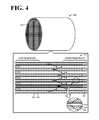
- the measurement specimens are prepared from the central honeycomb segment; when the honeycomb filter is an integrally formed product (refer to Fig. 4 described below), the measurement specimens are prepared from the central portions of the cross sections of the integrally formed product.
- the honeycomb filter 20 is measured by mercury porosimetry under conditions according to "Test methods for pore size distribution of fine ceramic green body by mercury porosimetry" in JIS-R1655.
- the honeycomb filter 20 may have a Log differential pore volume distribution of the downstream portion measured by mercury porosimetry in which a first pore volume peak is present in a first pore diameter range and a second pore volume peak that is higher than the first pore volume peak is present in a second pore diameter range that includes a second pore diameter that is larger than the pore diameter of the first pore volume peak; the honeycomb filter 20 may have a Log differential pore volume distribution of the upstream portion measured by mercury porosimetry in which the second pore volume peak in the second pore diameter range only is present.
- the trapping layers having a pore characteristic of a two-peak distribution in the downstream portion of the honeycomb filter 20
- the trapping layers can be coated with a catalyst in a larger amount in the downstream portion than that in the upstream portion of the honeycomb filter 20 and the PM combustion performance can be maintained even after combustion endurance.
- the first pore diameter range may be the range of 2 ⁇ m or more and 9 ⁇ m or less and the second pore diameter range may be the range of 10 ⁇ m or more and 25 ⁇ m or less.
- the first pore diameter range is 2 ⁇ m or more, an increase in the pressure loss due to low permeability can be avoided.
- the first pore diameter range is 9 ⁇ m or less, an increase in the pressure loss due to deposition of PM in the pores of the partition portions (bases) caused by insufficient trapping of PM can be avoided.
- the second pore diameter range is 10 ⁇ m or more, a rapid increase in the pressure loss due to clogging of pores in the partition portions by a catalyst can be avoided.
- the second pore diameter range is 25 ⁇ m or less, PM that is not trapped with the trapping layers can be trapped with the partition portions and hence the trapping performance is enhanced.
- the porosity of the upstream portion and the porosity of the downstream portion that are measured by mercury porosimetry may be in the range of 35% or more and 70% or less.
- the porosity of the upstream and downstream portions is 35% or more, an increase in the pressure loss due to a decrease in the permeability of the pores of the partition portions after coating with a catalyst can be avoided.
- the porosity of the upstream and downstream portions is 70% or less, the partition portions, the trapping layers, and the like have suitable pore volumes and a catalyst can be sufficiently loaded in the trapping layers. As a result, the problem that the PM combustion performance is degraded after combustion endurance can be avoided.
- the trapping layers 24 may be formed by using fluid as a transport medium of the raw material of the trapping layers and supplying a gas containing the raw material of the trapping layers to entry cells.
- the particle group forming the trapping layers can be formed as a coarse particle group and hence trapping layers having a high porosity can be formed, which is preferable.
- the fluid serving as the transport medium is preferably a gas such as the air or nitrogen gas.
- the raw material of the trapping layers may be, for example, inorganic fibers or inorganic particles.
- the inorganic fibers may be composed of the above-described inorganic materials and, for example, preferably have an average particle size of 0.5 ⁇ m or more and 8 ⁇ m or less and have an average length of 100 ⁇ m or more and 500 ⁇ m or less.
- the inorganic particles may be composed of the above-described inorganic materials.
- SiC particles or cordierite particles having an average particle size of 0.5 ⁇ m or more and 15 ⁇ m or less may be used.
- the raw material of the trapping layers preferably has an average particle size smaller than the average pore diameter of the partition portions 22.
- the inorganic materials of the partition portions 22 and the trapping layers 24 are preferably of the same type.
- a binder may be supplied together with inorganic fibers or inorganic particles.
- the binder may be selected from sol materials and colloid materials and is preferably, in particular, colloidal silica. It is preferred that the inorganic particles be covered with silica and bonded together with silica and that the inorganic particles and the material of the partition portions be bonded together with silica.
- the trapping layers 24 are preferably formed by forming layers of a raw material on the partition portions 22 and subsequently performing a heat treatment to achieve the bonding.
- the temperature of the heat treatment is preferably, for example, 650°C or more and 1350°C or less. When the heat treatment temperature is 650°C or more, a sufficiently high bonding strength can be achieved. When the heat treatment temperature is 1350°C or less, clogging of pores due to excessive oxidation of particles can be suppressed.
- the trapping layers 24 may be formed on the surfaces of the cells 23 with a slurry containing inorganic particles serving as a raw material of the trapping layers 24.
- the pore volumes of the upstream and downstream portions of the cells measured by mercury porosimetry, the pore volume peak characteristics, and the like can be controlled by properly setting conditions including the average particle size and particle size distribution of the raw material of the trapping layers, the feed rate (film-formation rate) of the raw material of the trapping layers, the flow rate of the fluid, and the particle size distribution and amount of a pore-forming agent.
- predetermined regions of the partition portions 22 such as the upstream and downstream regions of the honeycomb segments 21 contain alcohol, water, a resin, or the like to increase the permeation resistance to the fluid, regions where the raw-material particles of the trapping layers and a pore-forming agent that are fed are deposited can be controlled.
- values including a pore volume and a peak pore diameter can be varied in the upstream and downstream portions. Specifically, for example, after portions other than the downstream region are coated with resin so that fluid does not permeate the resin, a film of fine particles is formed only in the downstream region including the downstream portion.
- the coated resin is then removed by burning. Subsequently, to form a film in a certain region located upstream with respect to the downstream region in which the film has been formed, regions other than the region in which the film is to be formed are coated with resin and the film is formed of particles that are coarse, compared with the downstream region. Similar processes are repeated: as the film-formation region is gradually shifted upstream, a film is formed of coarser particles so that particles having different sizes are distributed in the axial direction. By adjusting the immersion time for coating with resin, a certain amount of the resin is also distributed in a boundary portion with respect to the non-coating region by capillarity and hence graded permeation resistance can be achieved in the boundary portion.
- the sharpness index Ds indicates the sharpness of the particle size distribution of the pore-forming agent having a predetermined average particle size (for example, 4 ⁇ m).
- the pore-forming agent may be composed of a material that can be removed by a heat treatment. For example, this material may be one or more selected from the group consisting of carbon black, coke, starch, rice powder, natural resin, and synthetic resin.
- the bonding layers 27 are used to bond the honeycomb segments 21 together and may contain inorganic particles, inorganic fibers, a binder, and the like.
- the inorganic particles may be particles of the above-described inorganic materials and preferably have an average particle size of 0.1 ⁇ m or more and 30 ⁇ m or less.
- the inorganic fibers may be formed so as to contain one or more materials selected from aluminosilicate, alumina, silica, zirconia, ceria, and mullite.
- the inorganic fibers preferably have an average particle size of 0.5 ⁇ m or more and 8 ⁇ m or less and an average length of 100 ⁇ m or more and 500 ⁇ m or less.
- the binder may be colloidal silica, clay, or the like.
- the bonding layers 27 are preferably formed so as to have a thickness of 0.5 mm or more and 2 mm or less.
- the circumferential protective portion 28 is used to protect the circumference of the honeycomb filter 20 and may contain the above-described inorganic particles, inorganic fibers, binder, and the like.
- the thermal expansion coefficient of the cells 23 in the channel direction at 40°C to 800°C is preferably 6.0 ⁇ 10 -6 /°C or less, more preferably 1.0 ⁇ 10 6 /°C or less, still more preferably 0.8 ⁇ 10 -6 /°C or less.
- the thermal expansion coefficient is 6.0 ⁇ 10 -6 /°C or less, thermal stress generated upon exposure to a high-temperature exhaust gas can be suppressed within the allowable range.
- the outer shape of the honeycomb filter 20 is not particularly limited and may be a cylindrical shape, a rectangular prism shape, an elliptic cylindrical shape, a hexagonal prism shape, or the like.
- the outer shape of the honeycomb segments 21 is not particularly limited and the honeycomb segments 21 preferably have planar surfaces suitable for bonding together.
- the honeycomb segments 21 may have a prism shape whose cross section has a polygonal shape (a rectangular prism shape, a hexagonal prism shape, or the like).
- the cross section of the cells may have a shape of a polygon such as a triangle, a quadrangle, a hexagon, or an octagon; a streamline shape such as a circular shape or an elliptic shape; or the shape of a combination of the foregoing.
- the cells 23 may be formed so as to have a quadrangular cross section perpendicular to the direction in which exhaust gas flows.
- the cell pitch is preferably 1.0 mm or more and 2.5 mm or less.
- the cell pitch, the cell density, and the thickness of the partition portions 22 are preferably determined in consideration of the tradeoff relationship relating to the initial pressure loss, the pressure loss upon the deposition of PM, and the trapping efficiency of PM.
- the honeycomb filter 20 may be loaded with a catalyst.
- This catalyst may be at least one of catalysts for promoting combustion of trapped PM, catalysts for oxidizing unburned gas (HCs, CO, and the like) contained in exhaust gas, and catalysts for storing/absorbing/decomposing NOx.
- PM can be efficiently removed; unburned gas can be efficiently oxidized; or NOx can be efficiently decomposed.
- a catalyst preferably contains one or more of noble metal elements and transition metal elements.
- the honeycomb filter 20 may be loaded with another catalyst or another cleaning agent: for example, a NOx storage catalyst containing an alkali metal (Li, Na, K, Cs, or the like) or an alkaline-earth metal (Ca, Ba, Sr, or the like), at least one rare-earth metal, a transition metal, a three-way catalyst, a promoter exemplified by cerium (Ce) oxide and/or zirconium (Zr) oxide, or a HC (hydrocarbon) adsorbent.
- the noble metal include platinum (Pt), palladium (Pd), rhodium (Rh), gold (Au), and silver (Ag).
- Examples of the transition metal contained in the catalyst include Mn, Fe, Co, Ni, Cu, Zn, Sc, Ti, V, and Cr.
- Examples of the rare-earth metal include Sm, Gd, Nd, Y, La, and Pr.
- Examples of the alkaline-earth metal include Mg, Ca, Sr, and Ba. Of these, platinum and palladium are preferred.
- Such a noble metal, a transition metal, a promoter, or the like may be loaded in a carrier having a large specific surface.
- Examples of the carrier include alumina, silica, silica alumina, and zeolite.
- pore volumes, pore distribution, and the like in the upstream and downstream portions of the honeycomb filter 20 are made to satisfy suitable ranges to thereby enhance the performances of trapping solid components contained in fluid: for example, a decrease in PM combustion percentage after endurance of combustion removal of deposited PM by forced regeneration can be further suppressed, clogging of the pores of the trapping layers can be further suppressed, and the pressure loss upon deposition of PM can be further reduced.
- the honeycomb segments 21 are bonded together with the bonding layers 27 to constitute the honeycomb filter 20.
- an integrally formed honeycomb filter 40 may be employed.
- partition portions 42, cells 43, trapping layers 44, sealing portions 46, and the like may have configurations similar to those of the partition portions 22, the cells 23, the trapping layers 24, the sealing portions 26, and the like of the honeycomb filter 20.
- the performance of trapping and removing PM contained in exhaust gas can also be further enhanced.
- the honeycomb filter 20 contains a catalyst. However, this is not particularly limitative as long as a substance that is contained in flowing fluid and intended to be removed can be cleaned.
- the honeycomb filter 20 may be provided without containing catalysts.
- the honeycomb filter 20 for trapping PM contained in exhaust gas has been described. However, this is not particularly limitative as long as a honeycomb filter for trapping and removing solid components contained in fluid is employed.
- a honeycomb filter for a power engine of construction machinery may be provided. Alternatively, a honeycomb filter for a plant or a power plant may be provided.
- honeycomb filters were specifically produced.
- the produced honeycomb filters had a structure in which a plurality of honeycomb segments were bonded together.
- a SiC powder and a metal Si powder were mixed at a mass ratio of 80:20. Methylcellulose, hydroxypropoxylmethylcellulose, a surfactant, and water were added to the mixture and the resultant mixture was kneaded to prepare a plastic pug.
- This pug was extruded with a predetermined die to form honeycomb segment formed bodies having a desired shape.
- the formed shape was as follows: the thickness of the partition portions was 305 ⁇ m; the cell pitch was 1.47 mm; the cross section was 35 mm ⁇ 35 mm; and the length was 152 mm.
- honeycomb segment formed bodies were then dried with microwaves, further dried with hot air, subsequently sealed, calcined in an oxidizing atmosphere at 550°C for 3 hours, and subsequently fired in an inert atmosphere at 1400°C for 2 hours.
- the sealing portions were formed by alternately masking cell openings in an end surface of each segment formed body and immersing the masked end surface into a sealing slurry containing a SiC raw material so that openings and sealing portions were alternately arranged.
- a mask was formed on the other end surface and the sealing portions were formed such that a cell having one end open and the other end sealed and a cell having one end sealed and the other end open were alternately arranged.
- the air containing SiC particles having an average particle size smaller than the average pore diameter of the partitions was made to flow from the opening end portions on the exhaust-gas entry side of the resultant honeycomb segment fired body while the air was suctioned from the exit side of the honeycomb segment to thereby deposit the SiC particles on the surfaces of the partitions on the exhaust-gas entry side.
- a pore distribution adjustment treatment described below for trapping layers was performed so that trapping layers in which pore distributions were adjusted in the upstream and downstream regions of the honeycomb filter were formed on the partition portions.
- honeycomb segments in which the trapping layers were formed on the partition portions were prepared. Side surfaces of the thus-prepared honeycomb segments were coated with a bonding slurry prepared by kneading alumina silicate fibers, colloidal silica, polyvinyl alcohol, SiC, and water. These honeycomb segments were combined together, bonded under pressure, and then dried by heating. Thus, a honeycomb segment assembly whose whole shape is a rectangular prism shape was obtained.
- the honeycomb segment assembly was ground so as to have a cylindrical shape.
- the circumference of the assembly was then covered with a circumference coating slurry composed of the same material as that of the bonding slurry.
- the slurry was cured by being dried to thereby provide a cylindrical honeycomb filter having a desired shape, a desired segment shape, and a desired cell structure.
- the honeycomb filter had a shape in which the diameter of a cross section was 144 mm, the length was 152 mm, the thickness of the partition portions was 300 ⁇ m, and the cell pitch was 1.47 mm.
- the porosity and the pore diameter of the partition portions were measured with a mercury porosimeter (manufactured by Micromeritics Instrument Corporation, Auto Pore III type 9405).
- the average particle size of the raw-material particles of the trapping layers was the median diameter (D50) measured with a laser diffraction/scattering particle size distribution analyzer (LA-910 manufactured by HORIBA, Ltd.) and with water serving as a dispersion medium.
- D50 median diameter measured with a laser diffraction/scattering particle size distribution analyzer (LA-910 manufactured by HORIBA, Ltd.) and with water serving as a dispersion medium.
- the SiC particles forming the particle group of the trapping layers were supplied together with the air and a pore-forming agent to each honeycomb segment to thereby deposit the SiC particles on the partition portions.
- the pore distribution can be controlled.
- starch was used as the pore-forming agent.
- the amount of the pore-forming agent added to the raw-material particles of the trapping layers be 3 mass% to 45 mass%
- the median particle diameter D50 of the pore-forming agent be 0.7 ⁇ m to 8.0 ⁇ m
- the sharpness index Ds of the particle size distribution of the pore-forming agent be 0.4 to 1.9
- the flow rate of the fluid be 780 L/min to 820 L/min
- values including a pore volume and a peak pore diameter were varied in the upstream and downstream portions.
- regions other than the downstream region were covered with resin. After the film formation in the downstream region, the resin was removed by burning and the downstream region was subsequently covered with resin and a film was formed in the regions other than the downstream region. In this way, the porosity and pore diameter were controlled for regions of the trapping layers.
- the exit end surface (from which exhaust gas flows out) of the honeycomb segment was then immersed to a predetermined height in the slurry while suction from the entry end surface (into which exhaust gas flows) was performed so as to be adjusted to a predetermined suction pressure and a predetermined suction rate for a predetermined time.
- the partitions were loaded with the catalyst.
- the honeycomb segment was dried at 120°C for 2 hours and then baked at 550°C for an hour.
- the amount of the catalyst per unit volume of the honeycomb filter was made to be 45 g/L.
- Pore distribution measurement by mercury porosimetry The pore distribution of the produced honeycomb filter was measured with a mercury porosimeter (manufactured by Micromeritics Instrument Corporation, Auto Pore III type 9405). As illustrated in Fig. 2 , measurement specimens were prepared in the following manner. The honeycomb filter was first cut so as to provide a cross section, at a portion that was away from the upstream end surface of the honeycomb filter by 20% of the entire length of the honeycomb filter. Three measurement specimens having sides of about 1 cm were cut from the central portion of the cross section (upstream specimens). Similarly, the honeycomb filter was cut so as to provide a cross section, at a portion that was away from the upstream end surface of the honeycomb filter by 50% of the entire length of the honeycomb filter.
- a measurement specimen having sides of about 1 cm was cut from the central portion of the cross section (midstream specimen).
- the honeycomb filter was cut so as to provide a cross section, at a portion that was away from the downstream end surface of the honeycomb filter by 20% of the entire length of the honeycomb filter.
- Three measurement specimens having sides of about 1 cm were cut from the central portion of the cross section (downstream specimens). These specimens were measured by mercury porosimetry in accordance with JIS-R1655.
- a honeycomb filter was defined as Experimental example 1 in which the second pore volume peak position was at 14 ⁇ m and the porosity was 40% in the upstream and midstream portions of the honeycomb filter, the second pore volume peak was at 14 ⁇ m and the porosity was 40% in the downstream portion of the honeycomb filter, and the pore volume difference obtained by subtracting the volume of pores having a diameter of 10 ⁇ m or less in the upstream portion from the volume of pores having a diameter of 10 ⁇ m or less in the downstream portion (hereafter, simply referred to as pore volume difference) was 0 cm 3 /g.
- a honeycomb filter produced as in Experimental example 1 except that the pore volume difference was made 0.01 cm 3 /g was defined as Experimental example 2.
- a honeycomb filter produced as in Experimental example 1 except that the pore volume difference was made 0.08 cm 3 /g was defined as Experimental example 6.
- the film-formation flow rate was made large so that the influence of pores constituted by gaps between raw-material particles was suppressed; a two-peak pore distribution was not formed and the influence of the volume of pores having a diameter of 10 ⁇ m or less only was evaluated.
- regions other than the downstream region were coated with resin and a film was formed only in the downstream region.
- the pore-forming agent was added in the amounts described in Table 1 to thereby control the volume of pores having a diameter of 10 ⁇ m or less.
- the resin was removed by burning and only the downstream portion (downstream region) in which the film had been formed was then coated with resin.
- a film was formed in a film-formation amount of 15 g/L and at a flow rate of 820 L/min without adding the pore-forming agent.
- a honeycomb filter was defined as Experimental example 8 in which, in the upstream and midstream portions of the honeycomb filter, the second pore volume peak position was at 14 ⁇ m and the porosity was 40%; in the downstream portion of the honeycomb filter, the first pore volume peak position was at 1 ⁇ m, the second pore volume peak position was at 14 ⁇ m, and the porosity was 40%; and the pore volume difference was 0.04 cm 3 /g.
- a honeycomb filter produced as in Experimental example 8 except that the first pore volume peak position in the downstream portion was made at 2 ⁇ m was defined as Experimental example 9.
- a honeycomb filter produced as in Experimental example 8 except that the first pore volume peak position in the downstream portion was made at 3 ⁇ m was defined as Experimental example 10.
- a honeycomb filter produced as in Experimental example 8 except that the first pore volume peak position in the downstream portion was made at 10 ⁇ m was defined as Experimental example 14.
- the first pore volume peak position in the downstream portion was adjusted.
- the pore distribution adjustment treatment performed will be described.
- the peak pore diameter of the first pore diameter was adjusted by changing the particle size of the pore-forming agent added to the film-formation raw material.
- Regions other than the downstream region were first coated with resin and a film was formed only in the downstream region including the downstream portion under conditions described in Table 2. After that, only the downstream portion (downstream region) in which the film had been formed was coated with resin. In the remaining upstream portion (upstream region), a film was formed in a film-formation amount of 15 g/L and at a flow rate of 820 L/min without adding the pore-forming agent.
- a honeycomb filter was defined as Experimental example 15 in which, in the upstream and midstream portions of the honeycomb filter, the second pore volume peak position was at 9 ⁇ m and the porosity was 40%; in the downstream portion of the honeycomb filter, the first pore volume peak position was at 4 ⁇ m, the second pore volume peak position was at 9 ⁇ m, and the porosity was 40%; and the pore volume difference was 0.04 cm 3 /g.
- a honeycomb filter produced as in Experimental example 15 except that the second pore volume peak position in the upstream, midstream, and downstream portions was made at 10 ⁇ m was defined as Experimental example 16.
- a honeycomb filter produced as in Experimental example 15 except that the second pore volume peak position in the upstream, midstream, and downstream portions was made at 12 ⁇ m was defined as Experimental example 17.
- a honeycomb filter produced as in Experimental example 15 except that the second pore volume peak position in the upstream, midstream, and downstream portions was made at 15 ⁇ m was defined as Experimental example 18.
- a honeycomb filter produced as in Experimental example 15 except that the second pore volume peak position in the upstream, midstream, and downstream portions was made at 20 ⁇ m was defined as Experimental example 19.
- a honeycomb filter produced as in Experimental example 15 except that the second pore volume peak position in the upstream, midstream, and downstream portions was made at 22 ⁇ m was defined as Experimental example 20.
- the second pore volume peak position in the upstream, midstream, and downstream portions was adjusted.
- the pore characteristics of the partition portions were controlled by adjusting the particle size distribution of the raw material and the pore-forming agent.
- a film was formed under conditions in which the film-formation amount was 15 g/L, a flow rate was 780 L/min, D50 of the pore-forming agent was 3.8 ⁇ m, and the amount of the pore-forming agent added was 20 mass%.
- a honeycomb filter was defined as Experimental example 23 in which, in the upstream, midstream, and downstream portions of the honeycomb filter, the second pore volume peak position was at 14 ⁇ m and the porosity was 33%; in the downstream portion, the first pore volume peak position was at 4 ⁇ m; and the pore volume difference was 0.04 cm 3 /g.
- a honeycomb filter produced as in Experimental example 23 except that the porosity in the upstream, midstream, and downstream portions was made 35% was defined as Experimental example 24.
- a honeycomb filter produced as in Experimental example 23 except that the porosity in the upstream, midstream, and downstream portions was made 40% was defined as Experimental example 25.
- a honeycomb filter produced as in Experimental example 23 except that the porosity in the upstream, midstream, and downstream portions was made 45% was defined as Experimental example 26.
- a honeycomb filter produced as in Experimental example 23 except that the porosity in the upstream, midstream, and downstream portions was made 50% was defined as Experimental example 27.
- a honeycomb filter produced as in Experimental example 23 except that the porosity in the upstream, midstream, and downstream portions was made 55% was defined as Experimental example 28.
- a honeycomb filter produced as in Experimental example 23 except that the porosity in the upstream, midstream, and downstream portions was made 60% was defined as Experimental example 29.
- a honeycomb filter produced as in Experimental example 23 except that the porosity in the upstream, midstream, and downstream portions was made 65% was defined as Experimental example 30.
- a honeycomb filter produced as in Experimental example 23 except that the porosity in the upstream, midstream, and downstream portions was made 70% was defined as Experimental example 31.
- a honeycomb filter produced as in Experimental example 23 except that the porosity in the upstream, midstream, and downstream portions was made 73% was defined as Experimental example 32.
- a honeycomb filter produced as in Experimental example 23 except that the porosity in the upstream, midstream, and downstream portions was made 75% was defined as Experimental example 33.
- honeycomb filters produced above were installed in a position directly below a 2.0-L diesel engine.
- the engine was maintained at 2500 rpm and 40 Nm and the pressure loss of the honeycomb filter during deposition of PM was measured.
- the honeycomb filter was removed from the engine and the weight of the honeycomb filter was measured. This weight was compared with the weight of the honeycomb filter before the test to thereby calculate the amount of PM deposition.
- the pressure loss at the time of deposition of 4 g/L was defined as the pressure loss of the measured honeycomb filter.
- Each of the honeycomb filters was aged in an electric furnace in the air atmosphere at a constant temperature of 850°C for 8 hours to thereby simulate endurance conditions in an actual car. After that, PM was deposited in 8 g/L in the same manner as in the pressure loss test. Forced regeneration was then performed by post injection under constant conditions of 2500 rpm and 40 Nm to increase the gas temperature at the entry of the honeycomb filter to 650°C and this state was maintained for 10 minutes. After the test, the weight of the honeycomb filter was measured. The regeneration efficiency was calculated from the amount of PM burnt with respect to 8 g/L. The resultant value was defined as the cleaning performance after aging.
- the smoke numbers were measured upstream and downstream of the honeycomb filter in the measurement of the pressure loss test.
- the ratio of trapping smoke due to passing through the honeycomb filter with respect to the smoke number at the entrance of the honeycomb filter was defined as the measured trapping efficiency.
- a device for measuring the smoke numbers was a smoke meter AVL 415S manufactured by AVL.
- Fig. 5 illustrates the measurement results of Log differential pore volume distributions in Experimental example 10.
- Fig. 6 illustrates the measurement results of Log differential pore volume distributions in Experimental example 29.
- Fig. 7 is a graph in terms of pressure loss, cleaning performance, and pore volume in Experimental examples 1 to 7.
- Fig. 8 is a graph in terms of pressure loss, cleaning performance, and the first pore volume peak in Experimental examples 8 to 14.
- Fig. 9 is a graph in terms of pressure loss, trapping performance, and the second pore volume peak in Experimental examples 15 to 22.
- Fig. 10 is a graph in terms of pressure loss, cleaning performance, and porosity in Experimental examples 23 to 33. As illustrated in Figs.
- a first pore volume peak was present in a first pore diameter range of 2 ⁇ m or more and 9 ⁇ m or less and a second pore volume peak that was higher than the first pore volume peak was present in a second pore diameter range of 10 ⁇ m or more and 25 ⁇ m or less; on the other hand, in the upstream portion of the honeycomb filter, only the second pore volume peak in the second pore diameter range of 10 ⁇ m or more and 25 ⁇ m or less was present. Since the pore volume in the downstream portion of the honeycomb filter was large, a larger amount of the trapping layers were probably formed in the downstream portion.
- Table 4 and Figs. 7 to 10 indicate that, when the pore volume difference in volume of pores having a diameter of 10 ⁇ m or less between the downstream portion and the upstream portion of a honeycomb filter was less than 0.01 cm 3 /g, the cleaning performance after aging (PM combustion percentage after heating) became poor. This is probably because the amount of the catalyst loaded in the downstream portion of the trapping layers was insufficient. On the other hand, when the pore volume difference was more than 0.08 cm 3 /g, the pressure loss at the time of PM deposition became high. This is probably because an excessively large amount of the catalyst was deposited in the pores of the trapping layers in the downstream region and the catalyst clogged the pores of the trapping layers.
- the pressure loss became high. This is probably because the permeability of the partition portions decreased.
- the first pore volume peak was present in a range of more than 9 ⁇ m, the pressure loss became high. This is probably because PM was not sufficiently trapped and PM deposited in pores of the partition portions and hence the pressure loss was increased.
- the second pore volume peak was present in a range of less than 10 ⁇ m, the pressure loss became high. This is probably because the catalyst clogged the pores of the partition portions and, as a result, a rapid increase in the pressure loss was caused.
- the second pore volume peak was present in a range of more than 25 ⁇ m, the trapping performance was degraded.
- a first pore volume peak is present in a first pore diameter range of 2 ⁇ m or more and 9 ⁇ m or less and a second pore volume peak that is higher than the first pore volume peak is present in a second pore diameter range of 10 ⁇ m or more and 25 ⁇ m or less; and, in an upstream portion, only the second pore volume peak in the second pore diameter range of 10 ⁇ m or more and 25 ⁇ m or less is present.
- the porosity of the partition portions is preferably in a range of 35% or more and 70% or less.
- the present invention can be suitably used as a honeycomb filer for cleaning exhaust gas from, for example, an engine of an automobile, or a stationary engine or a burning appliance for a construction machine and other industrial machines.
Landscapes
- Physics & Mathematics (AREA)
- Geometry (AREA)
- Chemical & Material Sciences (AREA)
- Chemical Kinetics & Catalysis (AREA)
- Filtering Materials (AREA)
- Processes For Solid Components From Exhaust (AREA)
- Filtering Of Dispersed Particles In Gases (AREA)
- Exhaust Gas Treatment By Means Of Catalyst (AREA)
- Porous Artificial Stone Or Porous Ceramic Products (AREA)
- Catalysts (AREA)
Applications Claiming Priority (1)
| Application Number | Priority Date | Filing Date | Title |
|---|---|---|---|
| JP2011064165A JP5604346B2 (ja) | 2011-03-23 | 2011-03-23 | ハニカムフィルタ |
Publications (2)
| Publication Number | Publication Date |
|---|---|
| EP2502660A1 true EP2502660A1 (fr) | 2012-09-26 |
| EP2502660B1 EP2502660B1 (fr) | 2014-05-14 |
Family
ID=45855515
Family Applications (1)
| Application Number | Title | Priority Date | Filing Date |
|---|---|---|---|
| EP12159148.1A Active EP2502660B1 (fr) | 2011-03-23 | 2012-03-13 | Filtre en nids d'abeilles |
Country Status (3)
| Country | Link |
|---|---|
| US (1) | US8802017B2 (fr) |
| EP (1) | EP2502660B1 (fr) |
| JP (1) | JP5604346B2 (fr) |
Cited By (4)
| Publication number | Priority date | Publication date | Assignee | Title |
|---|---|---|---|---|
| EP2505251A2 (fr) * | 2011-03-30 | 2012-10-03 | NGK Insulators, Ltd. | Filtre en nids d'abeilles |
| WO2014199210A1 (fr) * | 2013-06-10 | 2014-12-18 | Toyota Jidosha Kabushiki Kaisha | Filtre de purification de gaz d'échappement |
| WO2015060015A1 (fr) * | 2013-10-22 | 2015-04-30 | Toyota Jidosha Kabushiki Kaisha | Dispositif de purification d'échappement pour moteur à combustion interne |
| US10294838B2 (en) | 2012-12-03 | 2019-05-21 | Toyota Jidosha Kabushiki Kaisha | Exhaust purification filter |
Families Citing this family (19)
| Publication number | Priority date | Publication date | Assignee | Title |
|---|---|---|---|---|
| JP2013095637A (ja) * | 2011-11-01 | 2013-05-20 | Shinano Denki Seiren Kk | 球状α型炭化ケイ素、その製造方法、及び、該炭化ケイ素を原料としてなる焼結体又は有機樹脂複合体 |
| US9719385B2 (en) | 2012-03-30 | 2017-08-01 | Ibiden Co., Ltd. | Honeycomb filter |
| JP5843802B2 (ja) * | 2013-03-21 | 2016-01-13 | 日本碍子株式会社 | ハニカム触媒担体 |
| JP6091282B2 (ja) * | 2013-03-25 | 2017-03-08 | 日本碍子株式会社 | 触媒コートフィルタ及び触媒コートフィルタ用担体 |
| US9981255B2 (en) * | 2013-04-02 | 2018-05-29 | Hitachi Metals, Ltd. | Ceramic honeycomb structure and its production method |
| JP6293638B2 (ja) * | 2014-10-17 | 2018-03-14 | 株式会社キャタラー | 排ガス浄化装置 |
| JP6335823B2 (ja) * | 2015-03-25 | 2018-05-30 | 日本碍子株式会社 | ハニカム構造体、及びハニカム構造体の製造方法 |
| JP6581828B2 (ja) * | 2015-07-17 | 2019-09-25 | 日本碍子株式会社 | ハニカムフィルタ |
| JP2018183709A (ja) * | 2015-09-24 | 2018-11-22 | 住友化学株式会社 | ハニカムフィルタ及びハニカムフィルタの製造方法 |
| JP6934311B2 (ja) * | 2016-06-02 | 2021-09-15 | 株式会社キャタラー | 排ガス浄化フィルタ |
| JP6934436B2 (ja) * | 2018-03-02 | 2021-09-15 | 日本碍子株式会社 | 捕集フィルタ断面観察試料の作製方法、及び捕集フィルタにおける粒子状物質の捕集状態を評価する方法 |
| JP7118919B2 (ja) * | 2019-03-29 | 2022-08-16 | 株式会社Soken | 排ガス浄化フィルタ |
| JP6940786B2 (ja) * | 2019-07-31 | 2021-09-29 | 株式会社デンソー | 排ガス浄化フィルタ |
| JP7274395B2 (ja) * | 2019-10-11 | 2023-05-16 | 日本碍子株式会社 | ハニカム構造体 |
| JP7353217B2 (ja) * | 2020-03-02 | 2023-09-29 | 日本碍子株式会社 | ハニカムフィルタ |
| JP7353218B2 (ja) * | 2020-03-02 | 2023-09-29 | 日本碍子株式会社 | ハニカムフィルタ |
| JP7449720B2 (ja) * | 2020-03-02 | 2024-03-14 | 日本碍子株式会社 | ハニカムフィルタ |
| JP7449721B2 (ja) * | 2020-03-02 | 2024-03-14 | 日本碍子株式会社 | ハニカムフィルタ |
| JP2022152985A (ja) * | 2021-03-29 | 2022-10-12 | 日本碍子株式会社 | ハニカムフィルタ |
Citations (5)
| Publication number | Priority date | Publication date | Assignee | Title |
|---|---|---|---|---|
| EP0834343A1 (fr) * | 1996-10-03 | 1998-04-08 | Kabushiki Kaisha Toyota Chuo Kenkyusho | Filtre pour la purification des gaz d'échappement |
| WO2006041174A1 (fr) | 2004-10-12 | 2006-04-20 | Ibiden Co., Ltd. | Structure alveolaire ceramique |
| US20080004174A1 (en) * | 2006-06-13 | 2008-01-03 | Yusuke Itoh | Honeycomb-shaped substrate for catalyst and catalyst for purifying exhaust gases, catalyst which uses the same |
| WO2008136232A1 (fr) | 2007-04-27 | 2008-11-13 | Ngk Insulators, Ltd. | Filtre en nid d'abeilles |
| EP2108494A2 (fr) * | 2008-04-11 | 2009-10-14 | Ngk Insulators, Ltd. | Procédé de fabrication de structure en nid d'abeille |
Family Cites Families (9)
| Publication number | Priority date | Publication date | Assignee | Title |
|---|---|---|---|---|
| JP2004000838A (ja) * | 2002-05-31 | 2004-01-08 | Toyota Motor Corp | 排ガス浄化用触媒 |
| JP2004330118A (ja) * | 2003-05-09 | 2004-11-25 | Tokyo Yogyo Co Ltd | 排ガス浄化用フィルタ |
| US7776786B2 (en) * | 2004-05-04 | 2010-08-17 | Cormetech, Inc. | Catalyst systems advantageous for high particulate matter environments |
| WO2007094379A1 (fr) * | 2006-02-14 | 2007-08-23 | Ngk Insulators, Ltd. | Structure en nid d'abeille et corps de catalyseur en nid d'abeille |
| JP2007296512A (ja) * | 2006-04-05 | 2007-11-15 | Ngk Insulators Ltd | ハニカムフィルタ |
| JP2009136787A (ja) * | 2007-12-06 | 2009-06-25 | Honda Motor Co Ltd | 排ガス浄化用酸化触媒装置の製造方法 |
| JP2009255047A (ja) * | 2008-03-24 | 2009-11-05 | Ibiden Co Ltd | ハニカム構造体 |
| JP5291966B2 (ja) * | 2008-03-25 | 2013-09-18 | 日本碍子株式会社 | 触媒担持フィルタ |
| JP2009226375A (ja) * | 2008-03-25 | 2009-10-08 | Ngk Insulators Ltd | 触媒担持フィルタ |
-
2011
- 2011-03-23 JP JP2011064165A patent/JP5604346B2/ja active Active
-
2012
- 2012-03-12 US US13/417,770 patent/US8802017B2/en active Active
- 2012-03-13 EP EP12159148.1A patent/EP2502660B1/fr active Active
Patent Citations (7)
| Publication number | Priority date | Publication date | Assignee | Title |
|---|---|---|---|---|
| EP0834343A1 (fr) * | 1996-10-03 | 1998-04-08 | Kabushiki Kaisha Toyota Chuo Kenkyusho | Filtre pour la purification des gaz d'échappement |
| WO2006041174A1 (fr) | 2004-10-12 | 2006-04-20 | Ibiden Co., Ltd. | Structure alveolaire ceramique |
| EP1808217A1 (fr) * | 2004-10-12 | 2007-07-18 | Ibiden Co., Ltd. | Structure alveolaire ceramique |
| US20080004174A1 (en) * | 2006-06-13 | 2008-01-03 | Yusuke Itoh | Honeycomb-shaped substrate for catalyst and catalyst for purifying exhaust gases, catalyst which uses the same |
| WO2008136232A1 (fr) | 2007-04-27 | 2008-11-13 | Ngk Insulators, Ltd. | Filtre en nid d'abeilles |
| EP2158956A1 (fr) * | 2007-04-27 | 2010-03-03 | Ngk Insulator, Ltd. | Filtre en nid d'abeilles |
| EP2108494A2 (fr) * | 2008-04-11 | 2009-10-14 | Ngk Insulators, Ltd. | Procédé de fabrication de structure en nid d'abeille |
Cited By (6)
| Publication number | Priority date | Publication date | Assignee | Title |
|---|---|---|---|---|
| EP2505251A2 (fr) * | 2011-03-30 | 2012-10-03 | NGK Insulators, Ltd. | Filtre en nids d'abeilles |
| EP2505251A3 (fr) * | 2011-03-30 | 2013-06-12 | NGK Insulators, Ltd. | Filtre en nids d'abeilles |
| US10294838B2 (en) | 2012-12-03 | 2019-05-21 | Toyota Jidosha Kabushiki Kaisha | Exhaust purification filter |
| WO2014199210A1 (fr) * | 2013-06-10 | 2014-12-18 | Toyota Jidosha Kabushiki Kaisha | Filtre de purification de gaz d'échappement |
| WO2015060015A1 (fr) * | 2013-10-22 | 2015-04-30 | Toyota Jidosha Kabushiki Kaisha | Dispositif de purification d'échappement pour moteur à combustion interne |
| US9879585B2 (en) | 2013-10-22 | 2018-01-30 | Toyota Jidosha Kabushiki Kaisha | Exhaust purification device for internal combustion engine |
Also Published As
| Publication number | Publication date |
|---|---|
| US20120244042A1 (en) | 2012-09-27 |
| EP2502660B1 (fr) | 2014-05-14 |
| US8802017B2 (en) | 2014-08-12 |
| JP5604346B2 (ja) | 2014-10-08 |
| JP2012196656A (ja) | 2012-10-18 |
Similar Documents
| Publication | Publication Date | Title |
|---|---|---|
| EP2502660B1 (fr) | Filtre en nids d'abeilles | |
| EP2556872B1 (fr) | Filtre en nid d'abeilles | |
| EP2556871B1 (fr) | Filtre en nid d'abeilles | |
| JP5726414B2 (ja) | 触媒担持フィルタ、及び排ガス浄化システム | |
| EP2556885B1 (fr) | Filtre en nid d'abeilles et méthode de fabrication d'un filtre en nid d'abeilles | |
| EP2554234B1 (fr) | Filtre en nid d'abeilles | |
| JP5634983B2 (ja) | ハニカムフィルタ及びその製造方法 | |
| EP2108448B1 (fr) | Corps de catalyseur en nid d'abeille | |
| EP2554236B1 (fr) | Filtre en nid d'abeilles | |
| EP2554235B1 (fr) | Filtre en nid d'abeilles | |
| US8343252B2 (en) | Honeycomb filter | |
| EP2614874B1 (fr) | Filtre en nids d'abeilles | |
| EP2614872B1 (fr) | Filtre en nids d'abeilles | |
| EP2609980B1 (fr) | Filtre en nids d'abeilles | |
| EP2614873B1 (fr) | Filtre en nids d'abeilles |
Legal Events
| Date | Code | Title | Description |
|---|---|---|---|
| PUAI | Public reference made under article 153(3) epc to a published international application that has entered the european phase |
Free format text: ORIGINAL CODE: 0009012 |
|
| AK | Designated contracting states |
Kind code of ref document: A1 Designated state(s): AL AT BE BG CH CY CZ DE DK EE ES FI FR GB GR HR HU IE IS IT LI LT LU LV MC MK MT NL NO PL PT RO RS SE SI SK SM TR |
|
| AX | Request for extension of the european patent |
Extension state: BA ME |
|
| 17P | Request for examination filed |
Effective date: 20130313 |
|
| GRAP | Despatch of communication of intention to grant a patent |
Free format text: ORIGINAL CODE: EPIDOSNIGR1 |
|
| RIC1 | Information provided on ipc code assigned before grant |
Ipc: B01D 46/24 20060101AFI20131030BHEP |
|
| INTG | Intention to grant announced |
Effective date: 20131121 |
|
| GRAS | Grant fee paid |
Free format text: ORIGINAL CODE: EPIDOSNIGR3 |
|
| GRAA | (expected) grant |
Free format text: ORIGINAL CODE: 0009210 |
|
| AK | Designated contracting states |
Kind code of ref document: B1 Designated state(s): AL AT BE BG CH CY CZ DE DK EE ES FI FR GB GR HR HU IE IS IT LI LT LU LV MC MK MT NL NO PL PT RO RS SE SI SK SM TR |
|
| REG | Reference to a national code |
Ref country code: GB Ref legal event code: FG4D |
|
| REG | Reference to a national code |
Ref country code: AT Ref legal event code: REF Ref document number: 667809 Country of ref document: AT Kind code of ref document: T Effective date: 20140615 |
|
| REG | Reference to a national code |
Ref country code: IE Ref legal event code: FG4D |
|
| REG | Reference to a national code |
Ref country code: DE Ref legal event code: R096 Ref document number: 602012001644 Country of ref document: DE Effective date: 20140626 |
|
| REG | Reference to a national code |
Ref country code: NL Ref legal event code: VDEP Effective date: 20140514 Ref country code: AT Ref legal event code: MK05 Ref document number: 667809 Country of ref document: AT Kind code of ref document: T Effective date: 20140514 |
|
| REG | Reference to a national code |
Ref country code: LT Ref legal event code: MG4D |
|
| PG25 | Lapsed in a contracting state [announced via postgrant information from national office to epo] |
Ref country code: LT Free format text: LAPSE BECAUSE OF FAILURE TO SUBMIT A TRANSLATION OF THE DESCRIPTION OR TO PAY THE FEE WITHIN THE PRESCRIBED TIME-LIMIT Effective date: 20140514 Ref country code: GR Free format text: LAPSE BECAUSE OF FAILURE TO SUBMIT A TRANSLATION OF THE DESCRIPTION OR TO PAY THE FEE WITHIN THE PRESCRIBED TIME-LIMIT Effective date: 20140815 Ref country code: FI Free format text: LAPSE BECAUSE OF FAILURE TO SUBMIT A TRANSLATION OF THE DESCRIPTION OR TO PAY THE FEE WITHIN THE PRESCRIBED TIME-LIMIT Effective date: 20140514 Ref country code: NO Free format text: LAPSE BECAUSE OF FAILURE TO SUBMIT A TRANSLATION OF THE DESCRIPTION OR TO PAY THE FEE WITHIN THE PRESCRIBED TIME-LIMIT Effective date: 20140814 Ref country code: CY Free format text: LAPSE BECAUSE OF FAILURE TO SUBMIT A TRANSLATION OF THE DESCRIPTION OR TO PAY THE FEE WITHIN THE PRESCRIBED TIME-LIMIT Effective date: 20140514 Ref country code: IS Free format text: LAPSE BECAUSE OF FAILURE TO SUBMIT A TRANSLATION OF THE DESCRIPTION OR TO PAY THE FEE WITHIN THE PRESCRIBED TIME-LIMIT Effective date: 20140914 |
|
| PG25 | Lapsed in a contracting state [announced via postgrant information from national office to epo] |
Ref country code: HR Free format text: LAPSE BECAUSE OF FAILURE TO SUBMIT A TRANSLATION OF THE DESCRIPTION OR TO PAY THE FEE WITHIN THE PRESCRIBED TIME-LIMIT Effective date: 20140514 Ref country code: AT Free format text: LAPSE BECAUSE OF FAILURE TO SUBMIT A TRANSLATION OF THE DESCRIPTION OR TO PAY THE FEE WITHIN THE PRESCRIBED TIME-LIMIT Effective date: 20140514 Ref country code: SE Free format text: LAPSE BECAUSE OF FAILURE TO SUBMIT A TRANSLATION OF THE DESCRIPTION OR TO PAY THE FEE WITHIN THE PRESCRIBED TIME-LIMIT Effective date: 20140514 Ref country code: PL Free format text: LAPSE BECAUSE OF FAILURE TO SUBMIT A TRANSLATION OF THE DESCRIPTION OR TO PAY THE FEE WITHIN THE PRESCRIBED TIME-LIMIT Effective date: 20140514 Ref country code: RS Free format text: LAPSE BECAUSE OF FAILURE TO SUBMIT A TRANSLATION OF THE DESCRIPTION OR TO PAY THE FEE WITHIN THE PRESCRIBED TIME-LIMIT Effective date: 20140514 Ref country code: ES Free format text: LAPSE BECAUSE OF FAILURE TO SUBMIT A TRANSLATION OF THE DESCRIPTION OR TO PAY THE FEE WITHIN THE PRESCRIBED TIME-LIMIT Effective date: 20140514 Ref country code: LV Free format text: LAPSE BECAUSE OF FAILURE TO SUBMIT A TRANSLATION OF THE DESCRIPTION OR TO PAY THE FEE WITHIN THE PRESCRIBED TIME-LIMIT Effective date: 20140514 |
|
| PG25 | Lapsed in a contracting state [announced via postgrant information from national office to epo] |
Ref country code: PT Free format text: LAPSE BECAUSE OF FAILURE TO SUBMIT A TRANSLATION OF THE DESCRIPTION OR TO PAY THE FEE WITHIN THE PRESCRIBED TIME-LIMIT Effective date: 20140915 |
|
| PG25 | Lapsed in a contracting state [announced via postgrant information from national office to epo] |
Ref country code: DK Free format text: LAPSE BECAUSE OF FAILURE TO SUBMIT A TRANSLATION OF THE DESCRIPTION OR TO PAY THE FEE WITHIN THE PRESCRIBED TIME-LIMIT Effective date: 20140514 Ref country code: RO Free format text: LAPSE BECAUSE OF FAILURE TO SUBMIT A TRANSLATION OF THE DESCRIPTION OR TO PAY THE FEE WITHIN THE PRESCRIBED TIME-LIMIT Effective date: 20140514 Ref country code: CZ Free format text: LAPSE BECAUSE OF FAILURE TO SUBMIT A TRANSLATION OF THE DESCRIPTION OR TO PAY THE FEE WITHIN THE PRESCRIBED TIME-LIMIT Effective date: 20140514 Ref country code: SK Free format text: LAPSE BECAUSE OF FAILURE TO SUBMIT A TRANSLATION OF THE DESCRIPTION OR TO PAY THE FEE WITHIN THE PRESCRIBED TIME-LIMIT Effective date: 20140514 Ref country code: EE Free format text: LAPSE BECAUSE OF FAILURE TO SUBMIT A TRANSLATION OF THE DESCRIPTION OR TO PAY THE FEE WITHIN THE PRESCRIBED TIME-LIMIT Effective date: 20140514 Ref country code: BE Free format text: LAPSE BECAUSE OF FAILURE TO SUBMIT A TRANSLATION OF THE DESCRIPTION OR TO PAY THE FEE WITHIN THE PRESCRIBED TIME-LIMIT Effective date: 20140514 |
|
| REG | Reference to a national code |
Ref country code: DE Ref legal event code: R097 Ref document number: 602012001644 Country of ref document: DE |
|
| PG25 | Lapsed in a contracting state [announced via postgrant information from national office to epo] |
Ref country code: NL Free format text: LAPSE BECAUSE OF FAILURE TO SUBMIT A TRANSLATION OF THE DESCRIPTION OR TO PAY THE FEE WITHIN THE PRESCRIBED TIME-LIMIT Effective date: 20140514 |
|
| PLBE | No opposition filed within time limit |
Free format text: ORIGINAL CODE: 0009261 |
|
| STAA | Information on the status of an ep patent application or granted ep patent |
Free format text: STATUS: NO OPPOSITION FILED WITHIN TIME LIMIT |
|
| 26N | No opposition filed |
Effective date: 20150217 |
|
| PG25 | Lapsed in a contracting state [announced via postgrant information from national office to epo] |
Ref country code: IT Free format text: LAPSE BECAUSE OF FAILURE TO SUBMIT A TRANSLATION OF THE DESCRIPTION OR TO PAY THE FEE WITHIN THE PRESCRIBED TIME-LIMIT Effective date: 20140514 |
|
| REG | Reference to a national code |
Ref country code: DE Ref legal event code: R097 Ref document number: 602012001644 Country of ref document: DE Effective date: 20150217 |
|
| PG25 | Lapsed in a contracting state [announced via postgrant information from national office to epo] |
Ref country code: SI Free format text: LAPSE BECAUSE OF FAILURE TO SUBMIT A TRANSLATION OF THE DESCRIPTION OR TO PAY THE FEE WITHIN THE PRESCRIBED TIME-LIMIT Effective date: 20140514 |
|
| PG25 | Lapsed in a contracting state [announced via postgrant information from national office to epo] |
Ref country code: MC Free format text: LAPSE BECAUSE OF FAILURE TO SUBMIT A TRANSLATION OF THE DESCRIPTION OR TO PAY THE FEE WITHIN THE PRESCRIBED TIME-LIMIT Effective date: 20140514 Ref country code: LU Free format text: LAPSE BECAUSE OF FAILURE TO SUBMIT A TRANSLATION OF THE DESCRIPTION OR TO PAY THE FEE WITHIN THE PRESCRIBED TIME-LIMIT Effective date: 20150313 |
|
| REG | Reference to a national code |
Ref country code: CH Ref legal event code: PL |
|
| REG | Reference to a national code |
Ref country code: FR Ref legal event code: ST Effective date: 20151130 |
|
| REG | Reference to a national code |
Ref country code: IE Ref legal event code: MM4A |
|
| PG25 | Lapsed in a contracting state [announced via postgrant information from national office to epo] |
Ref country code: IE Free format text: LAPSE BECAUSE OF NON-PAYMENT OF DUE FEES Effective date: 20150313 Ref country code: CH Free format text: LAPSE BECAUSE OF NON-PAYMENT OF DUE FEES Effective date: 20150331 Ref country code: LI Free format text: LAPSE BECAUSE OF NON-PAYMENT OF DUE FEES Effective date: 20150331 |
|
| PG25 | Lapsed in a contracting state [announced via postgrant information from national office to epo] |
Ref country code: FR Free format text: LAPSE BECAUSE OF NON-PAYMENT OF DUE FEES Effective date: 20150331 |
|
| GBPC | Gb: european patent ceased through non-payment of renewal fee |
Effective date: 20160313 |
|
| PG25 | Lapsed in a contracting state [announced via postgrant information from national office to epo] |
Ref country code: MT Free format text: LAPSE BECAUSE OF FAILURE TO SUBMIT A TRANSLATION OF THE DESCRIPTION OR TO PAY THE FEE WITHIN THE PRESCRIBED TIME-LIMIT Effective date: 20140514 |
|
| PG25 | Lapsed in a contracting state [announced via postgrant information from national office to epo] |
Ref country code: GB Free format text: LAPSE BECAUSE OF NON-PAYMENT OF DUE FEES Effective date: 20160313 |
|
| PG25 | Lapsed in a contracting state [announced via postgrant information from national office to epo] |
Ref country code: HU Free format text: LAPSE BECAUSE OF FAILURE TO SUBMIT A TRANSLATION OF THE DESCRIPTION OR TO PAY THE FEE WITHIN THE PRESCRIBED TIME-LIMIT; INVALID AB INITIO Effective date: 20120313 Ref country code: SM Free format text: LAPSE BECAUSE OF FAILURE TO SUBMIT A TRANSLATION OF THE DESCRIPTION OR TO PAY THE FEE WITHIN THE PRESCRIBED TIME-LIMIT Effective date: 20140514 Ref country code: BG Free format text: LAPSE BECAUSE OF FAILURE TO SUBMIT A TRANSLATION OF THE DESCRIPTION OR TO PAY THE FEE WITHIN THE PRESCRIBED TIME-LIMIT Effective date: 20140514 |
|
| PG25 | Lapsed in a contracting state [announced via postgrant information from national office to epo] |
Ref country code: TR Free format text: LAPSE BECAUSE OF FAILURE TO SUBMIT A TRANSLATION OF THE DESCRIPTION OR TO PAY THE FEE WITHIN THE PRESCRIBED TIME-LIMIT Effective date: 20140514 |
|
| PG25 | Lapsed in a contracting state [announced via postgrant information from national office to epo] |
Ref country code: MK Free format text: LAPSE BECAUSE OF FAILURE TO SUBMIT A TRANSLATION OF THE DESCRIPTION OR TO PAY THE FEE WITHIN THE PRESCRIBED TIME-LIMIT Effective date: 20140514 |
|
| PG25 | Lapsed in a contracting state [announced via postgrant information from national office to epo] |
Ref country code: AL Free format text: LAPSE BECAUSE OF FAILURE TO SUBMIT A TRANSLATION OF THE DESCRIPTION OR TO PAY THE FEE WITHIN THE PRESCRIBED TIME-LIMIT Effective date: 20140514 |
|
| REG | Reference to a national code |
Ref country code: GB Ref legal event code: 732E Free format text: REGISTERED BETWEEN 20220113 AND 20220119 |
|
| PGFP | Annual fee paid to national office [announced via postgrant information from national office to epo] |
Ref country code: DE Payment date: 20240130 Year of fee payment: 13 |