EP2502124B1 - Wireless power utilization in a local computing environment - Google Patents
Wireless power utilization in a local computing environment Download PDFInfo
- Publication number
- EP2502124B1 EP2502124B1 EP10782483.1A EP10782483A EP2502124B1 EP 2502124 B1 EP2502124 B1 EP 2502124B1 EP 10782483 A EP10782483 A EP 10782483A EP 2502124 B1 EP2502124 B1 EP 2502124B1
- Authority
- EP
- European Patent Office
- Prior art keywords
- receiver device
- power supply
- power
- receiver
- coupling region
- Prior art date
- Legal status (The legal status is an assumption and is not a legal conclusion. Google has not performed a legal analysis and makes no representation as to the accuracy of the status listed.)
- Active
Links
- 230000008878 coupling Effects 0.000 claims description 49
- 238000010168 coupling process Methods 0.000 claims description 49
- 238000005859 coupling reaction Methods 0.000 claims description 49
- 230000005672 electromagnetic field Effects 0.000 claims description 24
- 238000000034 method Methods 0.000 claims description 20
- 238000004891 communication Methods 0.000 claims description 16
- 239000003990 capacitor Substances 0.000 description 20
- 108091006146 Channels Proteins 0.000 description 16
- 238000012546 transfer Methods 0.000 description 16
- 230000002093 peripheral effect Effects 0.000 description 15
- 230000005540 biological transmission Effects 0.000 description 13
- 230000008569 process Effects 0.000 description 6
- 238000013459 approach Methods 0.000 description 5
- 230000008859 change Effects 0.000 description 4
- 230000006870 function Effects 0.000 description 4
- 230000009467 reduction Effects 0.000 description 4
- 230000002829 reductive effect Effects 0.000 description 4
- 239000011800 void material Substances 0.000 description 4
- 230000001965 increasing effect Effects 0.000 description 3
- 230000007774 longterm Effects 0.000 description 3
- 230000009471 action Effects 0.000 description 2
- 230000008901 benefit Effects 0.000 description 2
- 230000007423 decrease Effects 0.000 description 2
- 238000010586 diagram Methods 0.000 description 2
- 230000000694 effects Effects 0.000 description 2
- 230000007613 environmental effect Effects 0.000 description 2
- 230000001939 inductive effect Effects 0.000 description 2
- 230000003993 interaction Effects 0.000 description 2
- 230000002452 interceptive effect Effects 0.000 description 2
- 230000000670 limiting effect Effects 0.000 description 2
- 230000007246 mechanism Effects 0.000 description 2
- 230000001404 mediated effect Effects 0.000 description 2
- 230000001902 propagating effect Effects 0.000 description 2
- 230000004044 response Effects 0.000 description 2
- 241001522296 Erithacus rubecula Species 0.000 description 1
- 239000004606 Fillers/Extenders Substances 0.000 description 1
- HBBGRARXTFLTSG-UHFFFAOYSA-N Lithium ion Chemical compound [Li+] HBBGRARXTFLTSG-UHFFFAOYSA-N 0.000 description 1
- 230000002411 adverse Effects 0.000 description 1
- 230000001668 ameliorated effect Effects 0.000 description 1
- 230000003321 amplification Effects 0.000 description 1
- 230000001413 cellular effect Effects 0.000 description 1
- 230000003247 decreasing effect Effects 0.000 description 1
- 238000012217 deletion Methods 0.000 description 1
- 230000037430 deletion Effects 0.000 description 1
- 230000001419 dependent effect Effects 0.000 description 1
- 238000001514 detection method Methods 0.000 description 1
- 229910001416 lithium ion Inorganic materials 0.000 description 1
- 230000005404 monopole Effects 0.000 description 1
- 238000003199 nucleic acid amplification method Methods 0.000 description 1
- 229920000642 polymer Polymers 0.000 description 1
- 230000005855 radiation Effects 0.000 description 1
- 229910000859 α-Fe Inorganic materials 0.000 description 1
Images


Classifications
-
- H—ELECTRICITY
- H02—GENERATION; CONVERSION OR DISTRIBUTION OF ELECTRIC POWER
- H02J—CIRCUIT ARRANGEMENTS OR SYSTEMS FOR SUPPLYING OR DISTRIBUTING ELECTRIC POWER; SYSTEMS FOR STORING ELECTRIC ENERGY
- H02J50/00—Circuit arrangements or systems for wireless supply or distribution of electric power
- H02J50/80—Circuit arrangements or systems for wireless supply or distribution of electric power involving the exchange of data, concerning supply or distribution of electric power, between transmitting devices and receiving devices
-
- G—PHYSICS
- G06—COMPUTING; CALCULATING OR COUNTING
- G06F—ELECTRIC DIGITAL DATA PROCESSING
- G06F1/00—Details not covered by groups G06F3/00 - G06F13/00 and G06F21/00
- G06F1/26—Power supply means, e.g. regulation thereof
-
- G—PHYSICS
- G06—COMPUTING; CALCULATING OR COUNTING
- G06F—ELECTRIC DIGITAL DATA PROCESSING
- G06F1/00—Details not covered by groups G06F3/00 - G06F13/00 and G06F21/00
- G06F1/26—Power supply means, e.g. regulation thereof
- G06F1/266—Arrangements to supply power to external peripherals either directly from the computer or under computer control, e.g. supply of power through the communication port, computer controlled power-strips
-
- H—ELECTRICITY
- H02—GENERATION; CONVERSION OR DISTRIBUTION OF ELECTRIC POWER
- H02J—CIRCUIT ARRANGEMENTS OR SYSTEMS FOR SUPPLYING OR DISTRIBUTING ELECTRIC POWER; SYSTEMS FOR STORING ELECTRIC ENERGY
- H02J50/00—Circuit arrangements or systems for wireless supply or distribution of electric power
- H02J50/10—Circuit arrangements or systems for wireless supply or distribution of electric power using inductive coupling
- H02J50/12—Circuit arrangements or systems for wireless supply or distribution of electric power using inductive coupling of the resonant type
-
- H—ELECTRICITY
- H02—GENERATION; CONVERSION OR DISTRIBUTION OF ELECTRIC POWER
- H02J—CIRCUIT ARRANGEMENTS OR SYSTEMS FOR SUPPLYING OR DISTRIBUTING ELECTRIC POWER; SYSTEMS FOR STORING ELECTRIC ENERGY
- H02J50/00—Circuit arrangements or systems for wireless supply or distribution of electric power
- H02J50/40—Circuit arrangements or systems for wireless supply or distribution of electric power using two or more transmitting or receiving devices
-
- H—ELECTRICITY
- H02—GENERATION; CONVERSION OR DISTRIBUTION OF ELECTRIC POWER
- H02J—CIRCUIT ARRANGEMENTS OR SYSTEMS FOR SUPPLYING OR DISTRIBUTING ELECTRIC POWER; SYSTEMS FOR STORING ELECTRIC ENERGY
- H02J7/00—Circuit arrangements for charging or depolarising batteries or for supplying loads from batteries
- H02J7/34—Parallel operation in networks using both storage and other dc sources, e.g. providing buffering
- H02J7/345—Parallel operation in networks using both storage and other dc sources, e.g. providing buffering using capacitors as storage or buffering devices
-
- H04B5/79—
-
- H04B5/70—
Definitions
- the described embodiments relate generally to utilizing a wireless power transmission in a portable computing environment.
- over-the-air or wireless power transmission between a transmitter and a receiver coupled to the electronic device to be charged have been carried out that generally fall into two categories.
- One category is based on the coupling of plane wave radiation between a transmit antenna and a receive antenna on the device to be charged.
- the receive antenna collects the radiated power and rectifies it for charging the battery.
- Antennas are generally of resonant length in order to improve the coupling efficiency. This approach suffers from the fact that the power coupling falls off quickly with distance between the antennas, so charging over reasonable distances (e.g., less than 1 to 2 meters) becomes difficult.
- Wireless power transmission in electronic devices is known from documents US 2009/271048 A1 , US 2009/134712 A1 and US 2009/058189 A1 .
- the invention is set out in the appended independent method claim 1 and independent computing device 6.
- the present invention provides a system and method for utilizing wireless near field magnetic resonance (NFMR) power transmission in a computing environment.
- NFMR wireless near field magnetic resonance
- a virtual charging area can be created.
- the virtual charging area can extend to about about one (1) meter from a central station that incorporates a NFMR power supply.
- the virtual charging area can define a region in which suitably configured peripheral devices, such as a mouse, keyboard, and so on can receive power by way of a NFMR channel formed between the NFRM power supply and a NFMR resonator circuit included in the peripheral device. In this way, when both the NFMR power supply and the NFMR resonator circuit are tuned to each other, then useable power can be transferred over a power conduction channel formed between the two resonant devices.
- At least one of the peripheral devices can have a tunable resonator circuit having at least one circuit element (such as a resistor, inductor, or capacitor) having a value that can be changed.
- the tunable resonator circuit can be de-coupled from the NFMR power supply by de-tuning the tunable resonator circuit in relation to the resonance frequency of the NFMR power supply. In this way, the effective Q value of the tunable circuit is reduced to the point that essentially no power is transferred.
- At least one of the plurality of peripheral devices can include a secondary NFMR resonator circuit adapted to re-resonant power to another one of the plurality of peripheral devices by establishing a NFMR channel to the other peripheral device over which useable power can be transferred.
- the NFMR power supply can eliminate any voids in the virtual charging area by modifying resonance characteristics such as frequency.
- a method of wirelessly transmitting power can be performed by creating a first coupling mode region of an electromagnetic field within a near field of a power supply transmit antenna, coupling the electromagnetic field and a receiver antenna of a first receiver device within the coupling mode region, creating a second coupling mode region of the electromagnetic field different from the first coupling mode region within a near field of a transmit antenna of the first receiver device, coupling the electromagnetic field to a receive antenna of second receiver device in the near field of the transmit antenna of the first receiver device, wirelessly delivering power from the power supply to the first receiver device by way of the power supply transmit antenna using the first coupling mode region of the electromagnetic field; and wirelessly delivering at least some of the power wirelessly delivered to the first receiver device is wirelessly by re-transmitting the at least some power to the second receiver device by way of the first receiver transmit antenna using the second coupling mode region of the electromagnetic field.
- the wireless powered local computing environment includes at least a near field magnetic resonance (NFMR) power supply arranged to wirelessly provide power to any of a number of suitably configured devices.
- the devices arranged to receive power wirelessly from the NFMR power supply can be located in a region known as the near field that extends no further than a distance D that can be a few times a characteristic size of the NFMR power supply transmission device.
- the distance D can be on the order of 1 meter or so.
- Fig. 1 shows various representative tunable circuits in accordance with the described embodiments.
- the representative tunable circuits can include series RLC (resistor (R), inductor (L), capacitor(C)) circuit 102.
- a resonant frequency can be tuned (i.e., changed) by changing any of the component values.
- circuit 102 capacitor C can be a variable capacitor used to tune circuit 102.
- circuit 104 (known as a Hartlely oscillator) can be used as a tunable circuit in the described embodiments as can tuned LC circuit 106.
- Fig. 2 shows representative virtual charging area 200 in accordance with the described embodiments.
- Virtual charging area 200 provides region R of charging for suitably configured devices placed within the region R.
- NFMR power supply can be placed in central unit such as desktop computer. In this way, the desktop computer can provide the NFMR power supply with computing resources.
- the near field magnetic resonance (NFMR) power supply can include high Q circuit that relies upon near field magnetic coupling by way of a resonance channel formed between resonances of the power source and sink to transfer power.
- the NFMR power supply can be a standalone unit such as, for example, included in a desk top computer, laptop computer, tablet computer, and so on.
- the NFMR power supply can take the form of a portable type unit such as a dongle that can be connected to a legacy device such as a desktop computer thereby providing the ability to retrofit devices.
- housing or a portion of a housing used to enclose the NFMR power source can act to extend a useful range of the NFMR power supply.
- peripheral devices can be powered directly from the NFMR power supply.
- the peripheral devices when tuned to the appropriate frequency can receive power wirelessly from the NFMR power supply.
- the appropriately tuned peripheral device can be considered to be part of a resonance circuit that can include the NFMR power supply and any other peripheral devices so tuned.
- each device has associated with it a corresponding load that can be sensed by the NFMR power supply.
- the resonance circuit can have a characteristic load that can change by the addition or deletion of devices from the resonance circuit.
- any change in the characteristic load factor of the resonance circuit can convey information that can be used by the NFMR power supply to control the various devices in the resonance circuit by, for example, distributing power, and so on.
- certain of the peripheral devices can be configured to include a re-resonator circuit that can receive power directly from the NFMR power supply. Such devices can also transfer a portion of the power received to other of the peripheral devices.
- virtual charging area 200 includes central unit 202 (desktop computer) that can include the NFMR power supply, keyboard 204, mouse 206, and portable media player 208.
- keyboard 204 can be configured to receive power directly from the NFMR power supply included in desktop computer 202 as can mouse 206 and portable media player 208 (when located within range R).
- keyboard 204 can act as a re-resonator such that a portion of the power delivered to keyboard 204 from the NFMR power supply can be passed on by way of a re-resonator transmission unit (not shown) in keyboard 204. In this way, any power loss experienced by mouse 206 can be ameliorated by the power received from keyboard 204.
- This arrangement can be transitory or can last for as long as mouse 206 is not able to receive adequate power directly from the NFMR power supply.
- the locating of portable media player 208 within region R can reduce the amount of power available to keyboard 204 and mouse 206. In this case, if a battery in keyboard 206 is fully charged (or additional charge is not necessary) then keyboard 206 can decouple a charging circuit while still maintaining a re-resonator circuit providing power to mouse 206.
- dongle 210 can be connected to desktop computer 202 (by way of a USB port or cable, for example). So connected, dongle 210 can, in turn, act as a range extender for the NFMR power supply. In this way, dongle 210 can extend a range that power can be provided by the NFMR power supply included in desktop computer 202. In some cases, dongle 210 can re-resonate power already received from the NFMR power supply while in other cases, dongle 210 can include its own NFMR power supply. By having its own NFMR power supply, dongle 210 can provide additional power wirelessly to those devices within virtual charging region 200 separate from the power provided by the NFMR power supply included in desktop 202. It should be noted that in some embodiments, the housing of desktop computer 202 (or a portion thereof) can be used as a resonator as part of the NFMR power supply.
- Fig. 3 shows representative hybrid power circuit 300 in accordance with the described embodiments.
- hybrid power circuit 300 can match the low power delivery capability of the NFMR power supply to a large power requirement of required for long term storage devices, such as lithium ion polymer (LiPO) battery. Batteries in such devices as portable phones, portable media players, and so on, can require relatively large amount of power to charge that can be greater than that available from the NFMR power supply. Therefore, it is difficult to charge these high capacity batteries such as LiPO using the NFMR power supply.
- a short term charge storage device such as a capacitor, ultra capacitor, and so on
- a short term charge storage device such as a capacitor, ultra capacitor, and so on
- Fig. 3 shows representative hybrid power circuit 300 having capacitor 302, capacitor charging circuit 304 (that can receive power P from the NFMR power supply), long term power storage unit 306 (that can take the form of battery 306), and battery charging circuit 308.
- power P provided by the NFMR power supply can "trickle" charge capacitor 302.
- capacitor charging circuit 304 can sense capacitor voltage VC and switch fully charged capacitor 302 to battery 306 by way of battery charging circuit 308. In this way, charge Q stored in capacitor 302 can be used to increase the charge of battery 306.
- capacitor 302 is discharged (as determined by capacitor charging circuit 304), capacitor 302 can again receive power P from the NFMR power supply.
- One of the advantages of a wirelessly powered local computing environment is the potential to provide an enhanced user experience. For example, by doing away with clumsy and annoying cables and eliminating the need to replace batteries, an easy to use and efficient local computing environment can be provided to the user.
- an easy to use and efficient local computing environment can be provided to the user.
- an amount of power transferred between the NFMR power supply (having a first resonator circuit) and receiving device (having a second resonator circuit) can be controlled by tuning (or de-tuning) the second resonator circuit along the lines described above.
- tuning or de-tuning the second resonator circuit along the lines described above.
- a load associated with the device can be "seen” by the NFMR power supply. This load can, in turn, be used by the NFMR power supply to determine the power requirements of the resonance circuit as well as how the required power must be distributed amongst the various devices included in the resonance circuit.
- a device "de-tunes" then the device no longer resonates with the NFMR power supply and is effectively removed from the resonance circuit and receives little or no additional power.
- any object metal, for example
- This reduction in power transferred or power transfer efficiency can put an undue strain on the NFMR power supply as well as increase the likelihood that particular devices may not have sufficient power to operate at peak efficiency, to execute important functions, or in some cases, not be able to operate at all.
- feedback provided by a device to the NFMR power supply indicating that the device requires more power or has experienced a reduction in power can cause the NFMR power supply to try to ascertain the reason or reasons why the device has experienced this reduction in power. For example, if the device is moving within a void region (a void being defined as that region having a substantially reduced power transmission or efficiency factor), then the NFMR power supply can attempt to move the void region by modifying selected resonance factors (such as resonance frequency) thereby having the effect of moving the void region (hopefully beyond the range of the operating region of the devices wirelessly coupled to the NFMR power supply).
- selected resonance factors such as resonance frequency
- the NFMR power supply can determine that the power transfer efficiency has dropped below a threshold for a device(s) based upon, for example, feedback from the affected device(s). In response, the NFMR power supply can respond by modifying the frequency of the magnetic resonance signal until the power efficiency has recovered to above the threshold, by increasing power, or by, in some cases, causing less important or less used devices, to de-tune themselves (thereby removing themselves from the resonance circuit) so as to free up power that can be provided to those devices requiring more power. It should be noted that these operations can be carried out in the background in such a way that the user is unaware of the operations taking place. In still another embodiment, the power source can alter phase, frequency and or signal amplitude relative to other links in order to optimize power delivery.
- each device can provide affirmative feedback to the NFMR power supply using a direct communication channel such as Bluetooth or WiFi.
- a direct communication channel such as Bluetooth or WiFi.
- an indirect communication channel can also be used.
- Such an indirect communication channel can be formed using the resonance circuit load factor mediated by the number (and type) of devices wirelessly coupled with the NFMR power supply. Since each device has an associated resonance load (i.e., load perceived by the NFMR power supply when a device is tuned to the proper resonance frequency), an indirect communication channel mediated by load state of the device, or devices in the resonance circuit can be established with the NFMR power supply.
- the NFMR power supply can characterize a particular load state of a resonance circuit by ascertaining the overall resonance load (i.e., sense load on resonant circuit). Any changes to the load state can indicate a change in the status of the resonance circuit which, in turn, can infer that one or more of the devices previously included in the resonance circuit (i.e., tuned to the NFMR power supply resonant frequency) has dropped out, or de-tuned.
- a Morse code like communication protocol can be established between the NFRM power supply and each of the devices. This Morse code like communication protocol can be based upon a device tuning and de-tuning itself using an identifiable pattern.
- a simple device identifier for example, can be communicated to the NFMR power supply.
- a device that has determined to de-tune itself and to remove itself from the resonance circuit can signal the NFMR power supply its intent as well as identify itself.
- the NFRM power supply can have a more clear understanding of the condition of the resonance circuit and the devices included therein.
- This device to device communication channel (also referred to as a back channel) can be capable of communicating simple information. Such information can include, for example, a device identifier, a synchronization flag, and so on. It should be noted that this communication channel is independent and separate from other communication channels provided by, for example, WiFi or Bluetooth.
- the keyboard can determine that power from the NFMR power supply is no longer required (at least until the battery discharges to a pre-set level). In this case, the keyboard can notify the NFMR power supply that it no longer requires power (or at least until it signals that it requires power at some future point in time). In this case, the NFMR can redirect power away from the keyboard (using, for example, a different resonant frequency when the NFMR power supply is equipped to transmit power on a number of frequency ranges, or bands) or the keyboard can remove itself from the resonance circuit (either on its own or as directed) by de-tuning itself.
- the load of the resonance circuit can be reduced allowing more power to be wirelessly delivered to the other devices in the resonance circuit.
- the NFMR power supply will provide only as much power as is needed. For example, as battery charges up then less power is required. In this way, the charge state of the battery can be communicated to the NFMR power supply that can respond by reducing, or throttling back, the power provided to the keyboard.
- a device can be removed from the resonance circuit by the process of de-tuning, the device can be added to the resonance circuit by tuning it.
- tuning it is meant that circuit characteristics (such as resistance) can be changed resulting in the circuit Q increasing in the case of tuning or decreasing in the case of de-tuning.
- circuit characteristics such as resistance
- the relative increase or decrease in Q for a circuit can be dependent upon the circuit and applications to which the circuit is used.
- proximity detection can be thought as having taken place that can trigger an action to be taken. For example, if a portable media player is brought within range R of a desktop computer, then the proximity signal generated by the change in load experienced by the power supply can cause the desktop computer to initiate a synchronization process, for example, between the portable media player and the desktop computer.
- the communication channels established between the various devices in the resonance circuit can be used for the devices to determine amongst themselves which device takes priority with regards to power supplied by the NFMR power supply.
- a host device that includes the NFMR power supply and any associated computing resources
- aggregator it is meant that the host device can determine the priority of those devices for receiving power, how much power to receive, and for how long.
- some devices and or some operations performed by a device can have a higher priority than other devices and or operations.
- a high priority device(s) may require guaranteed power for operation (such as using a mouse vs charging a portable media player).
- the host device can use any suitable priority mechanism (round robin, for example).
- the devices receiving power can communicate amongst themselves to determine which device has priority.
- the devices understand their own operating points, such as a minimum amount of power to perform certain function, maximum power required to perform all functions. In this way, each device can provide a desired amount of power, a list of functions that can be performed, and a minimum amount of power required for operation.
- the source can determine how much power can be delivered and which device can get the power it needs.
- the devices themselves set the priority, in other cases, the host device sets the priority. When a device is not receiving power, it removes itself from the resonance circuit by de-tuning, and returns to the circuit by re-tuning.
- the NFMR power supply can use any number of protocols to wirelessly provide power to the various devices included in the resonance circuit.
- the NFMR power supply can include a plurality of resonator circuits each arranged to resonate at a particular frequency. In this way, the NFMR power supply can provide power orthogonally using different frequency bands. In this way, a device can have multiple resonant frequencies in order to take advantage of the frequency bands provided by the NFMR power supply.
- the NFMR power supply can wirelessly provide power using multiple frequency bands where a number of devices can each tune themselves to a particular frequency. In this way, frequency shifting techniques can be used to more efficiently transfer power to the plurality of devices within range of the NFMR power supply.
- Fig. 4 Other mechanisms for a single NFMR power supply to independently transmit power to more than one device includes time multiplexing as shown in Fig. 4 .
- devices 400, 402 and 404 can each take turns tuning and de-tuning themselves such that at any one time only one of the devices if receiving power. For example, during a period 1, device 400 receives power by tuning itself to at least one of the available resonant frequencies while devices 402 and 404 are de-tuned. Once device 400 has completed its power cycle, device 400 de-tunes itself and device 402 tunes itself and receives power wirelessly from the NFMR power supply.
- the NFMR power supply can use frequency multiplexing in which the NFMR can toggle amongst a number of frequencies each one tuned to a particular device. The device can receive power only when the device resonates with a current frequency of the power supply.
- the closed loop control can also affect the modes of operation of the devices in the resonance circuit.
- a keyboard can determine an amount of power received from the source which will depend upon the distance between the source and the keyboard (as well as the presence of any interfering objects). If the power received falls below a threshold, then the keyboard can use more battery power or request that the source increase power. In some cases, if the power provided can not be increased to meet the current operating requirements of the keyboard, then the keyboard can take action to reduce its power requirements by, for example, reducing backlight, etc. It should be noted that as discussed above, the reduction on power received by the keyboard can be caused by many other factors other than an increase in distance. Such factors can include, for example, the presence of voids, objects, other devices added to the circuit, and so on.
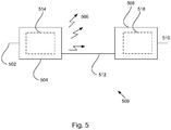
- Fig. 5 illustrates a wireless transmission or charging system 500, in accordance with various exemplary embodiments.
- Input power 502 is provided to a transmitter 504 for generating a radiated field 506 for providing energy transfer.
- a receiver 508 couples to the radiated field 506 and generates an output power 510 for storing or consumption by a device (not shown) coupled to the output power 510. Both the transmitter 504 and the receiver 508 are separated by a distance 512.
- transmitter 504 and receiver 508 are configured according to a mutual resonant relationship and when the resonant frequency of receiver 508 and the resonant frequency of transmitter 504 are very close, transmission losses between the transmitter 504 and the receiver 508 are minimal when the receiver 508 is located in the "near-field" of the radiated field 506.
- Transmitter 504 further includes a transmit antenna 514 for providing a means for energy transmission and receiver 508 further includes a receive antenna 518 for providing a means for energy reception.
- the transmit and receive antennas are sized according to applications and devices to be associated therewith. As stated, an efficient energy transfer occurs by coupling a large portion of the energy in the near-field of the transmitting antenna to a receiving antenna rather than propagating most of the energy in an electromagnetic wave to the far field. When in this near-field a coupling mode may be developed between the transmit antenna 514 and the receive antenna 518. The area around the antennas 514 and 518 where this near-field coupling may occur is referred to herein as a coupling-mode region.
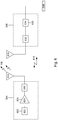
- Fig. 6 shows a simplified schematic diagram of a wireless power transfer system.
- the transmitter 604 includes an oscillator 622, a power amplifier 624 and a filter and matching circuit 626.
- the oscillator is configured to generate a desired frequency, which may be adjusted in response to adjustment signal 623.
- the oscillator signal may be amplified by the power amplifier 624 with an amplification amount responsive to control signal 625.
- the filter and matching circuit 626 may be included to filter out harmonics or other unwanted frequencies and match the impedance of the transmitter 604 to the transmit antenna 514.
- the receiver 608 may include a matching circuit 632 and a rectifier and switching circuit 634 to generate a DC power output to charge a battery 636 as shown in FIG. 6 or power a device coupled to the receiver (not shown).
- the matching circuit 632 may be included to match the impedance of the receiver 508 to the receive antenna 518.
- the receiver 508 and transmitter 504 may communicate on a separate communication channel 619 (e.g., Bluetooth, zigbee, cellular, etc).
- antennas used in exemplary embodiments may be configured as a "loop" antenna 750, which may also be referred to herein as a "magnetic" antenna.
- Loop antennas may be configured to include an air core or a physical core such as a ferrite core. Air core loop antennas may be more tolerable to extraneous physical devices placed in the vicinity of the core. Furthermore, an air core loop antenna allows the placement of other components within the core area. In addition, an air core loop may more readily enable placement of the receive antenna 518 ( FIG. 5 , 6 ) within a plane of the transmit antenna5 ( FIG. 5 , 6 ) where the coupled-mode region of the transmit antenna 514 ( FIG. 5 , 6 ) may be more powerful.
- the resonant frequency of the loop or magnetic antennas is based on the inductance and capacitance.
- Inductance in a loop antenna is generally simply the inductance created by the loop, whereas, capacitance is generally added to the loop antenna's inductance to create a resonant structure at a desired resonant frequency.
- capacitor 752 and capacitor 754 may be added to the antenna to create a resonant circuit that generates resonant signal 756. Accordingly, for larger diameter loop antennas, the size of capacitance needed to induce resonance decreases as the diameter or inductance of the loop increases. Furthermore, as the diameter of the loop or magnetic antenna increases, the efficient energy transfer area of the near-field increases.
- resonant circuits are possible.
- a capacitor may be placed in parallel between the two terminals of the loop antenna.
- the resonant signal 756 may be an input to the loop antenna 750.
- Exemplary embodiments of the invention include coupling power between two antennas that are in the near-fields of each other.
- the near-field is an area around the antenna in which electromagnetic fields exist but may not propagate or radiate away from the antenna. They are typically confined to a volume that is near the physical volume of the antenna.
- magnetic type antennas such as single and multi-turn loop antennas are used for both transmit (Tx) and receive (Rx) antenna systems since magnetic near-field amplitudes tend to be higher for magnetic type antennas in comparison to the electric near-fields of an electric-type antenna (e.g., a small dipole). This allows for potentially higher coupling between the pair.
- "electric" antennas e.g., dipoles and monopoles
- a combination of magnetic and electric antennas is also contemplated.
- the Tx antenna can be operated at a frequency that is low enough and with an antenna size that is large enough to achieve good coupling (e.g., >-4 dB) to a small Rx antenna at significantly larger distances than allowed by far field and inductive approaches mentioned earlier. If the Tx antenna is sized correctly, high coupling levels (e.g., -1 to -4 dB) can be achieved when the Rx antenna on a host device is placed within a coupling-mode region (i.e., in the near-field) of the driven Tx loop antenna.
- a coupling-mode region i.e., in the near-field
- Fig. 8 shows a flowchart detailing process 800 in accordance with the described embodiments.
- Process 800 can begin at 802 by creating a first coupling mode region of an electromagnetic field within a near field of a power supply transmit antenna.
- the electromagnetic field and a receiver antenna of a first receiver device are coupled with the coupling mode region.
- a second coupling mode region of the electromagnetic field different from the first coupling mode region is created with a near field of a transmit antenna of the first receiver device.
- the electromagnetic field is coupled to a receive antenna of second receiver device in the near field of the transmit antenna of the first receiver device.
- power is wirelessly delivered from the power supply to the first receiver device by way of the power supply transmit antenna using the first coupling mode region of the electromagnetic field.
- at least some of the power wirelessly delivered to the first receiver device is wirelessly re-transmitted to the second receiver device by way of the first receiver transmit antenna using the second coupling mode region of the electromagnetic field.
Applications Claiming Priority (2)
| Application Number | Priority Date | Filing Date | Title |
|---|---|---|---|
| US26208609P | 2009-11-17 | 2009-11-17 | |
| PCT/US2010/056240 WO2011062827A2 (en) | 2009-11-17 | 2010-11-10 | Wireless power utilization in a local computing environment |
Publications (2)
| Publication Number | Publication Date |
|---|---|
| EP2502124A2 EP2502124A2 (en) | 2012-09-26 |
| EP2502124B1 true EP2502124B1 (en) | 2020-02-19 |
Family
ID=43569471
Family Applications (1)
| Application Number | Title | Priority Date | Filing Date |
|---|---|---|---|
| EP10782483.1A Active EP2502124B1 (en) | 2009-11-17 | 2010-11-10 | Wireless power utilization in a local computing environment |
Country Status (7)
| Country | Link |
|---|---|
| US (3) | US9086864B2 (zh) |
| EP (1) | EP2502124B1 (zh) |
| JP (4) | JP2013511255A (zh) |
| KR (5) | KR101491400B1 (zh) |
| CN (2) | CN102612674B (zh) |
| TW (1) | TWI464992B (zh) |
| WO (1) | WO2011062827A2 (zh) |
Families Citing this family (134)
| Publication number | Priority date | Publication date | Assignee | Title |
|---|---|---|---|---|
| US7825543B2 (en) | 2005-07-12 | 2010-11-02 | Massachusetts Institute Of Technology | Wireless energy transfer |
| KR101136889B1 (ko) | 2005-07-12 | 2012-04-20 | 메사추세츠 인스티튜트 오브 테크놀로지 | 무선 비-방사성 에너지 전달 |
| US9421388B2 (en) | 2007-06-01 | 2016-08-23 | Witricity Corporation | Power generation for implantable devices |
| US8115448B2 (en) | 2007-06-01 | 2012-02-14 | Michael Sasha John | Systems and methods for wireless power |
| EP2281322B1 (en) | 2008-05-14 | 2016-03-23 | Massachusetts Institute of Technology | Wireless energy transfer, including interference enhancement |
| US8552592B2 (en) | 2008-09-27 | 2013-10-08 | Witricity Corporation | Wireless energy transfer with feedback control for lighting applications |
| US8497601B2 (en) | 2008-09-27 | 2013-07-30 | Witricity Corporation | Wireless energy transfer converters |
| US9601270B2 (en) | 2008-09-27 | 2017-03-21 | Witricity Corporation | Low AC resistance conductor designs |
| US8912687B2 (en) | 2008-09-27 | 2014-12-16 | Witricity Corporation | Secure wireless energy transfer for vehicle applications |
| US8587153B2 (en) | 2008-09-27 | 2013-11-19 | Witricity Corporation | Wireless energy transfer using high Q resonators for lighting applications |
| US9601261B2 (en) | 2008-09-27 | 2017-03-21 | Witricity Corporation | Wireless energy transfer using repeater resonators |
| US8487480B1 (en) | 2008-09-27 | 2013-07-16 | Witricity Corporation | Wireless energy transfer resonator kit |
| US8901779B2 (en) | 2008-09-27 | 2014-12-02 | Witricity Corporation | Wireless energy transfer with resonator arrays for medical applications |
| US8643326B2 (en) | 2008-09-27 | 2014-02-04 | Witricity Corporation | Tunable wireless energy transfer systems |
| US9318922B2 (en) | 2008-09-27 | 2016-04-19 | Witricity Corporation | Mechanically removable wireless power vehicle seat assembly |
| US8922066B2 (en) | 2008-09-27 | 2014-12-30 | Witricity Corporation | Wireless energy transfer with multi resonator arrays for vehicle applications |
| US8957549B2 (en) | 2008-09-27 | 2015-02-17 | Witricity Corporation | Tunable wireless energy transfer for in-vehicle applications |
| US8587155B2 (en) | 2008-09-27 | 2013-11-19 | Witricity Corporation | Wireless energy transfer using repeater resonators |
| US8471410B2 (en) | 2008-09-27 | 2013-06-25 | Witricity Corporation | Wireless energy transfer over distance using field shaping to improve the coupling factor |
| US8937408B2 (en) | 2008-09-27 | 2015-01-20 | Witricity Corporation | Wireless energy transfer for medical applications |
| US8901778B2 (en) | 2008-09-27 | 2014-12-02 | Witricity Corporation | Wireless energy transfer with variable size resonators for implanted medical devices |
| US9160203B2 (en) | 2008-09-27 | 2015-10-13 | Witricity Corporation | Wireless powered television |
| US8324759B2 (en) | 2008-09-27 | 2012-12-04 | Witricity Corporation | Wireless energy transfer using magnetic materials to shape field and reduce loss |
| US9065423B2 (en) | 2008-09-27 | 2015-06-23 | Witricity Corporation | Wireless energy distribution system |
| US8692410B2 (en) | 2008-09-27 | 2014-04-08 | Witricity Corporation | Wireless energy transfer with frequency hopping |
| US8723366B2 (en) | 2008-09-27 | 2014-05-13 | Witricity Corporation | Wireless energy transfer resonator enclosures |
| EP3544196B1 (en) | 2008-09-27 | 2023-09-13 | WiTricity Corporation | Wireless energy transfer systems |
| US9601266B2 (en) | 2008-09-27 | 2017-03-21 | Witricity Corporation | Multiple connected resonators with a single electronic circuit |
| US9035499B2 (en) | 2008-09-27 | 2015-05-19 | Witricity Corporation | Wireless energy transfer for photovoltaic panels |
| US8569914B2 (en) | 2008-09-27 | 2013-10-29 | Witricity Corporation | Wireless energy transfer using object positioning for improved k |
| US8400017B2 (en) | 2008-09-27 | 2013-03-19 | Witricity Corporation | Wireless energy transfer for computer peripheral applications |
| US8476788B2 (en) | 2008-09-27 | 2013-07-02 | Witricity Corporation | Wireless energy transfer with high-Q resonators using field shaping to improve K |
| US9396867B2 (en) | 2008-09-27 | 2016-07-19 | Witricity Corporation | Integrated resonator-shield structures |
| US8461720B2 (en) | 2008-09-27 | 2013-06-11 | Witricity Corporation | Wireless energy transfer using conducting surfaces to shape fields and reduce loss |
| US9577436B2 (en) | 2008-09-27 | 2017-02-21 | Witricity Corporation | Wireless energy transfer for implantable devices |
| US8441154B2 (en) | 2008-09-27 | 2013-05-14 | Witricity Corporation | Multi-resonator wireless energy transfer for exterior lighting |
| US9544683B2 (en) | 2008-09-27 | 2017-01-10 | Witricity Corporation | Wirelessly powered audio devices |
| US8304935B2 (en) | 2008-09-27 | 2012-11-06 | Witricity Corporation | Wireless energy transfer using field shaping to reduce loss |
| US9105959B2 (en) | 2008-09-27 | 2015-08-11 | Witricity Corporation | Resonator enclosure |
| US9515494B2 (en) | 2008-09-27 | 2016-12-06 | Witricity Corporation | Wireless power system including impedance matching network |
| US9246336B2 (en) | 2008-09-27 | 2016-01-26 | Witricity Corporation | Resonator optimizations for wireless energy transfer |
| US8461721B2 (en) | 2008-09-27 | 2013-06-11 | Witricity Corporation | Wireless energy transfer using object positioning for low loss |
| US8598743B2 (en) | 2008-09-27 | 2013-12-03 | Witricity Corporation | Resonator arrays for wireless energy transfer |
| US8772973B2 (en) | 2008-09-27 | 2014-07-08 | Witricity Corporation | Integrated resonator-shield structures |
| US8907531B2 (en) | 2008-09-27 | 2014-12-09 | Witricity Corporation | Wireless energy transfer with variable size resonators for medical applications |
| US8946938B2 (en) | 2008-09-27 | 2015-02-03 | Witricity Corporation | Safety systems for wireless energy transfer in vehicle applications |
| US8692412B2 (en) | 2008-09-27 | 2014-04-08 | Witricity Corporation | Temperature compensation in a wireless transfer system |
| US8466583B2 (en) | 2008-09-27 | 2013-06-18 | Witricity Corporation | Tunable wireless energy transfer for outdoor lighting applications |
| US8933594B2 (en) | 2008-09-27 | 2015-01-13 | Witricity Corporation | Wireless energy transfer for vehicles |
| US9093853B2 (en) | 2008-09-27 | 2015-07-28 | Witricity Corporation | Flexible resonator attachment |
| US9184595B2 (en) | 2008-09-27 | 2015-11-10 | Witricity Corporation | Wireless energy transfer in lossy environments |
| US8963488B2 (en) | 2008-09-27 | 2015-02-24 | Witricity Corporation | Position insensitive wireless charging |
| US8461722B2 (en) | 2008-09-27 | 2013-06-11 | Witricity Corporation | Wireless energy transfer using conducting surfaces to shape field and improve K |
| US9744858B2 (en) | 2008-09-27 | 2017-08-29 | Witricity Corporation | System for wireless energy distribution in a vehicle |
| US8410636B2 (en) | 2008-09-27 | 2013-04-02 | Witricity Corporation | Low AC resistance conductor designs |
| US8686598B2 (en) | 2008-09-27 | 2014-04-01 | Witricity Corporation | Wireless energy transfer for supplying power and heat to a device |
| US8629578B2 (en) | 2008-09-27 | 2014-01-14 | Witricity Corporation | Wireless energy transfer systems |
| US9106203B2 (en) | 2008-09-27 | 2015-08-11 | Witricity Corporation | Secure wireless energy transfer in medical applications |
| US8669676B2 (en) | 2008-09-27 | 2014-03-11 | Witricity Corporation | Wireless energy transfer across variable distances using field shaping with magnetic materials to improve the coupling factor |
| US8928276B2 (en) | 2008-09-27 | 2015-01-06 | Witricity Corporation | Integrated repeaters for cell phone applications |
| US8482158B2 (en) | 2008-09-27 | 2013-07-09 | Witricity Corporation | Wireless energy transfer using variable size resonators and system monitoring |
| US8947186B2 (en) | 2008-09-27 | 2015-02-03 | Witricity Corporation | Wireless energy transfer resonator thermal management |
| US8362651B2 (en) | 2008-10-01 | 2013-01-29 | Massachusetts Institute Of Technology | Efficient near-field wireless energy transfer using adiabatic system variations |
| KR101491400B1 (ko) * | 2009-11-17 | 2015-02-06 | 애플 인크. | 로컬 컴퓨팅 환경에서의 무선 전력 이용 |
| US9602168B2 (en) | 2010-08-31 | 2017-03-21 | Witricity Corporation | Communication in wireless energy transfer systems |
| US9030053B2 (en) | 2011-05-19 | 2015-05-12 | Choon Sae Lee | Device for collecting energy wirelessly |
| KR101813011B1 (ko) | 2011-05-27 | 2017-12-28 | 삼성전자주식회사 | 무선 전력 및 데이터 전송 시스템 |
| WO2012166125A1 (en) * | 2011-05-31 | 2012-12-06 | Apple Inc. | Automatically tuning a transmitter to a resonance frequency of a receiver |
| US9323298B2 (en) * | 2011-06-30 | 2016-04-26 | Broadcom Corporation | Adaptive power management |
| US9948145B2 (en) | 2011-07-08 | 2018-04-17 | Witricity Corporation | Wireless power transfer for a seat-vest-helmet system |
| US9384885B2 (en) | 2011-08-04 | 2016-07-05 | Witricity Corporation | Tunable wireless power architectures |
| TWI442664B (zh) * | 2011-08-19 | 2014-06-21 | Primax Electronics Ltd | 無線電腦周邊裝置之無線充電方法 |
| US9448603B2 (en) * | 2011-09-03 | 2016-09-20 | Leigh M. Rothschild | Transferring power to a mobile device |
| WO2013036947A2 (en) | 2011-09-09 | 2013-03-14 | Witricity Corporation | Foreign object detection in wireless energy transfer systems |
| US20130062966A1 (en) | 2011-09-12 | 2013-03-14 | Witricity Corporation | Reconfigurable control architectures and algorithms for electric vehicle wireless energy transfer systems |
| US9318257B2 (en) | 2011-10-18 | 2016-04-19 | Witricity Corporation | Wireless energy transfer for packaging |
| CN103988391A (zh) | 2011-11-04 | 2014-08-13 | WiTricity公司 | 无线能量传输建模工具 |
| KR101910194B1 (ko) * | 2011-11-07 | 2018-10-22 | 엘에스전선 주식회사 | 멀티 충전이 가능한 무선 전력 송수신 시스템 |
| JP2015508987A (ja) | 2012-01-26 | 2015-03-23 | ワイトリシティ コーポレーションWitricity Corporation | 減少した場を有する無線エネルギー伝送 |
| TWI456859B (zh) * | 2012-03-02 | 2014-10-11 | Hsiung Kuang Tsai | 無線電力傳輸系統 |
| US9755437B2 (en) | 2012-04-25 | 2017-09-05 | Nokia Technologies Oy | Method, apparatus, and computer program product for wireless charging detection |
| DE102012103942A1 (de) * | 2012-05-04 | 2013-11-07 | Wittenstein Ag | Energieübertragungssystem |
| KR101863968B1 (ko) | 2012-06-01 | 2018-06-04 | 한국전자통신연구원 | 에너지 전송 시스템에서 무선 에너지 송수신 장치 및 그 방법 |
| US9343922B2 (en) | 2012-06-27 | 2016-05-17 | Witricity Corporation | Wireless energy transfer for rechargeable batteries |
| US9287607B2 (en) | 2012-07-31 | 2016-03-15 | Witricity Corporation | Resonator fine tuning |
| US9595378B2 (en) | 2012-09-19 | 2017-03-14 | Witricity Corporation | Resonator enclosure |
| CN109969007A (zh) | 2012-10-19 | 2019-07-05 | 韦特里西提公司 | 无线能量传输系统中的外来物检测 |
| US9449757B2 (en) | 2012-11-16 | 2016-09-20 | Witricity Corporation | Systems and methods for wireless power system with improved performance and/or ease of use |
| KR101767276B1 (ko) | 2012-12-03 | 2017-08-10 | 한국전자통신연구원 | 무선 전력 전송을 이용하는 배터리 충전 방법 및 시스템 |
| US9543790B2 (en) | 2013-01-24 | 2017-01-10 | Electronics And Telecommunications Research Institute | Apparatus for transmitting magnetic resonance wireless power using higher order mode resonance, receiving terminal, and method for transmitting and receiving wireless power using the same |
| US10468914B2 (en) | 2013-03-11 | 2019-11-05 | Robert Bosch Gmbh | Contactless power transfer system |
| US9601928B2 (en) | 2013-03-14 | 2017-03-21 | Choon Sae Lee | Device for collecting energy wirelessly |
| WO2014178575A1 (ko) * | 2013-04-30 | 2014-11-06 | 인텔렉추얼 디스커버리 주식회사 | 무선 전력 송수신 장치 및 무선 전력 송수신 방법 |
| US9490653B2 (en) * | 2013-07-23 | 2016-11-08 | Qualcomm Incorporated | Systems and methods for enabling a universal back-cover wireless charging solution |
| CN104377741B (zh) * | 2013-08-12 | 2019-04-05 | 中兴通讯股份有限公司 | 移动终端相互间无线充电的方法及移动终端 |
| JP2016534698A (ja) | 2013-08-14 | 2016-11-04 | ワイトリシティ コーポレーションWitricity Corporation | インピーダンス同調 |
| US10038340B2 (en) | 2013-10-21 | 2018-07-31 | Electronics And Telecommunications Research Institute | Wireless power transmission method and apparatus for improving spectrum efficiency and space efficiency based on impedance matching and relay resonance |
| US9325184B2 (en) * | 2013-12-19 | 2016-04-26 | Qualcomm Technologies International, Ltd. | Apparatus for wirelessly charging a rechargeable battery |
| US20150188765A1 (en) * | 2013-12-31 | 2015-07-02 | Microsoft Corporation | Multimode gaming server |
| US10114431B2 (en) * | 2013-12-31 | 2018-10-30 | Microsoft Technology Licensing, Llc | Nonhomogeneous server arrangement |
| US9780573B2 (en) | 2014-02-03 | 2017-10-03 | Witricity Corporation | Wirelessly charged battery system |
| US20150229135A1 (en) | 2014-02-10 | 2015-08-13 | Shahar Porat | Wireless load modulation |
| WO2015123614A2 (en) | 2014-02-14 | 2015-08-20 | Witricity Corporation | Object detection for wireless energy transfer systems |
| US9892849B2 (en) | 2014-04-17 | 2018-02-13 | Witricity Corporation | Wireless power transfer systems with shield openings |
| US9842687B2 (en) | 2014-04-17 | 2017-12-12 | Witricity Corporation | Wireless power transfer systems with shaped magnetic components |
| US9837860B2 (en) | 2014-05-05 | 2017-12-05 | Witricity Corporation | Wireless power transmission systems for elevators |
| WO2015171910A1 (en) | 2014-05-07 | 2015-11-12 | Witricity Corporation | Foreign object detection in wireless energy transfer systems |
| US9954375B2 (en) | 2014-06-20 | 2018-04-24 | Witricity Corporation | Wireless power transfer systems for surfaces |
| US10574091B2 (en) | 2014-07-08 | 2020-02-25 | Witricity Corporation | Enclosures for high power wireless power transfer systems |
| US9842688B2 (en) | 2014-07-08 | 2017-12-12 | Witricity Corporation | Resonator balancing in wireless power transfer systems |
| KR20160051497A (ko) | 2014-11-03 | 2016-05-11 | 주식회사 한림포스텍 | 무선 전력 전송 네트워크의 전력 전송 커버리지 제어 장치 및 방법 |
| US9843217B2 (en) | 2015-01-05 | 2017-12-12 | Witricity Corporation | Wireless energy transfer for wearables |
| US10248899B2 (en) | 2015-10-06 | 2019-04-02 | Witricity Corporation | RFID tag and transponder detection in wireless energy transfer systems |
| EP3362804B1 (en) | 2015-10-14 | 2024-01-17 | WiTricity Corporation | Phase and amplitude detection in wireless energy transfer systems |
| WO2017070227A1 (en) | 2015-10-19 | 2017-04-27 | Witricity Corporation | Foreign object detection in wireless energy transfer systems |
| US10141788B2 (en) | 2015-10-22 | 2018-11-27 | Witricity Corporation | Dynamic tuning in wireless energy transfer systems |
| JP6702688B2 (ja) * | 2015-10-22 | 2020-06-03 | キヤノン株式会社 | 無線電力伝送システム及び受電装置 |
| US10075019B2 (en) | 2015-11-20 | 2018-09-11 | Witricity Corporation | Voltage source isolation in wireless power transfer systems |
| US10038332B1 (en) * | 2015-12-24 | 2018-07-31 | Energous Corporation | Systems and methods of wireless power charging through multiple receiving devices |
| KR102492190B1 (ko) | 2016-01-11 | 2023-01-27 | 삼성전자주식회사 | 무선 전력 전송 장치, 무선 충전 시스템 및 이들의 제어 방법 |
| CA3012325A1 (en) | 2016-02-02 | 2017-08-10 | Witricity Corporation | Controlling wireless power transfer systems |
| KR102612384B1 (ko) | 2016-02-08 | 2023-12-12 | 위트리시티 코포레이션 | Pwm 커패시터 제어 |
| US10277058B2 (en) * | 2016-05-16 | 2019-04-30 | Qualcomm Incorporated | Near field communication (NFC) coexistance |
| CN106451684B (zh) | 2016-12-08 | 2019-08-16 | 华为技术有限公司 | 一种智能控制无线充电的方法、设备及其系统 |
| US10381878B1 (en) | 2016-12-29 | 2019-08-13 | X Development Llc | Adapter for electronic devices |
| KR102328712B1 (ko) | 2017-03-03 | 2021-11-22 | 삼성전자주식회사 | 무선 전력 전송을 위한 전송 장치 및 이의 제어 방법 |
| CN111108662B (zh) | 2017-06-29 | 2023-12-12 | 韦特里西提公司 | 无线电力系统的保护和控制 |
| CN107919740B (zh) * | 2017-12-08 | 2020-06-05 | 哈尔滨理工大学 | 一种失谐因子实现谐振系统参数设计的方法 |
| KR102095498B1 (ko) * | 2017-12-28 | 2020-04-28 | 주식회사 유라코퍼레이션 | 차량내 무선 충전 시스템 및 방법 |
| KR102433881B1 (ko) | 2018-02-14 | 2022-08-19 | 삼성전자주식회사 | 전자 장치 및 그 제어 방법 |
| JP2019153044A (ja) * | 2018-03-02 | 2019-09-12 | トッパン・フォームズ株式会社 | 電子機器リセットシステム、電子機器リセット方法、電子機器及びリセット装置 |
| KR102538112B1 (ko) * | 2018-04-18 | 2023-05-31 | 삼성전자주식회사 | 무선으로 전력을 공급하는 디스플레이 시스템 |
| KR20210016795A (ko) * | 2019-08-05 | 2021-02-17 | 주식회사 엘지화학 | 에너지 허브 장치 및 에너지 관리 방법 |
| TWI774058B (zh) * | 2020-09-11 | 2022-08-11 | 寶德科技股份有限公司 | 鍵盤裝置以及周邊裝置組合 |
Family Cites Families (87)
| Publication number | Priority date | Publication date | Assignee | Title |
|---|---|---|---|---|
| JPS54152886A (en) * | 1978-05-23 | 1979-12-01 | Mitsubishi Electric Corp | Transponder checking device |
| US5701121A (en) * | 1988-04-11 | 1997-12-23 | Uniscan Ltd. | Transducer and interrogator device |
| JPH09204950A (ja) | 1996-01-26 | 1997-08-05 | Matsushita Electric Works Ltd | マルチメディア用配線器具 |
| CN1253960C (zh) | 1997-01-03 | 2006-04-26 | 滑动环及设备制造有限公司 | 用于非接触传输电信号的装置 |
| WO1998037926A1 (en) * | 1997-02-26 | 1998-09-03 | Alfred E. Mann Foundation For Scientific Research | Battery-powered patient implantable device |
| DE19836401A1 (de) | 1997-09-19 | 2000-02-17 | Salcomp Oy Salo | Vorrichtung zum Aufladen von Akkumulatoren |
| US7522878B2 (en) * | 1999-06-21 | 2009-04-21 | Access Business Group International Llc | Adaptive inductive power supply with communication |
| US7212414B2 (en) * | 1999-06-21 | 2007-05-01 | Access Business Group International, Llc | Adaptive inductive power supply |
| JP3932787B2 (ja) * | 1999-10-25 | 2007-06-20 | セイコーエプソン株式会社 | チョッパ回路、チョッパ回路の制御方法、チョッパ式充電回路、電子機器及び計時装置 |
| AU2001238595A1 (en) | 2000-02-22 | 2001-09-03 | Shearwater Corporation | N-maleimidyl polymer derivatives |
| US6970142B1 (en) | 2001-08-16 | 2005-11-29 | Raytheon Company | Antenna configurations for reduced radar complexity |
| US6633155B1 (en) * | 2002-05-06 | 2003-10-14 | Hui-Pin Liang | Wireless mouse induction power supply |
| US6844702B2 (en) * | 2002-05-16 | 2005-01-18 | Koninklijke Philips Electronics N.V. | System, method and apparatus for contact-less battery charging with dynamic control |
| US8183827B2 (en) * | 2003-01-28 | 2012-05-22 | Hewlett-Packard Development Company, L.P. | Adaptive charger system and method |
| BRPI0411593A (pt) * | 2003-06-17 | 2006-08-29 | Ecosol Solar Technologies Inc | dispositivo de armazenamento de energia de dois estágios |
| JP2005143181A (ja) | 2003-11-05 | 2005-06-02 | Seiko Epson Corp | 非接触電力伝送装置 |
| JP2005151609A (ja) | 2003-11-11 | 2005-06-09 | Sony Ericsson Mobilecommunications Japan Inc | 携帯型電子装置 |
| JP2005210843A (ja) | 2004-01-23 | 2005-08-04 | Toyota Motor Corp | 電力供給システム、車載電源装置及び路側電源装置 |
| CN1829037A (zh) * | 2005-03-03 | 2006-09-06 | 陈居阳 | 具无线充电系统的电池装置及其方法 |
| JP2006314181A (ja) | 2005-05-09 | 2006-11-16 | Sony Corp | 非接触充電装置及び非接触充電システム並びに非接触充電方法 |
| KR101136889B1 (ko) | 2005-07-12 | 2012-04-20 | 메사추세츠 인스티튜트 오브 테크놀로지 | 무선 비-방사성 에너지 전달 |
| US7825543B2 (en) | 2005-07-12 | 2010-11-02 | Massachusetts Institute Of Technology | Wireless energy transfer |
| US8447234B2 (en) * | 2006-01-18 | 2013-05-21 | Qualcomm Incorporated | Method and system for powering an electronic device via a wireless link |
| CN2919568Y (zh) | 2006-01-26 | 2007-07-04 | 友劲科技股份有限公司 | 适用于无线网络装置上的平板天线 |
| CN101375509A (zh) | 2006-01-31 | 2009-02-25 | 鲍尔卡斯特公司 | 电力传输网络和方法 |
| EP2027705A2 (en) | 2006-06-14 | 2009-02-25 | Powercast Corporation | Wireless power transmission |
| ATE498944T1 (de) | 2006-06-27 | 2011-03-15 | Sensormatic Electronics Corp | Resonanzschaltkreis-abstimmsystem mit dynamischer impedanzanpassung |
| US7570220B2 (en) | 2006-06-27 | 2009-08-04 | Sensormatic Electronics Corporation | Resonant circuit tuning system with dynamic impedance matching |
| US8463332B2 (en) | 2006-08-31 | 2013-06-11 | Semiconductor Energy Laboratory Co., Ltd. | Wireless communication device |
| US7839124B2 (en) | 2006-09-29 | 2010-11-23 | Semiconductor Energy Laboratory Co., Ltd. | Wireless power storage device comprising battery, semiconductor device including battery, and method for operating the wireless power storage device |
| JP2008178195A (ja) | 2007-01-17 | 2008-07-31 | Seiko Epson Corp | 送電制御装置、受電制御装置、無接点電力伝送システム、送電装置、受電装置及び電子機器 |
| US9774086B2 (en) | 2007-03-02 | 2017-09-26 | Qualcomm Incorporated | Wireless power apparatus and methods |
| WO2009145747A1 (en) | 2007-05-24 | 2009-12-03 | Face Bradbury R | Lighting fixture with low voltage transformer & self-powered switching system |
| JP2008301645A (ja) | 2007-06-01 | 2008-12-11 | Sanyo Electric Co Ltd | 非接触式受電装置及びこれを具えた電子機器 |
| US8115448B2 (en) | 2007-06-01 | 2012-02-14 | Michael Sasha John | Systems and methods for wireless power |
| CN101803224A (zh) * | 2007-08-13 | 2010-08-11 | 高通股份有限公司 | 远程低频率谐振器和材料 |
| JP5359090B2 (ja) * | 2007-09-13 | 2013-12-04 | 株式会社リコー | 電源装置、スキャナ用電源装置及び画像形成装置 |
| EP2201641A1 (en) | 2007-09-17 | 2010-06-30 | Qualcomm Incorporated | Transmitters and receivers for wireless energy transfer |
| KR101473600B1 (ko) | 2007-09-17 | 2014-12-16 | 퀄컴 인코포레이티드 | 무선 전력 자기 공진기에서의 고효율 및 고전력 전송 |
| TWI431889B (zh) | 2007-09-28 | 2014-03-21 | Access Business Group Int Llc | 多相感應電源供應系統 |
| JP5073440B2 (ja) * | 2007-10-15 | 2012-11-14 | シャープ株式会社 | テレメータシステムおよび無線通信システム |
| JP4600464B2 (ja) | 2007-11-22 | 2010-12-15 | セイコーエプソン株式会社 | 送電制御装置、送電装置、電子機器及び無接点電力伝送システム |
| CN107086677A (zh) * | 2007-11-28 | 2017-08-22 | 高通股份有限公司 | 使用寄生天线的无线功率射程增加 |
| JP5362330B2 (ja) | 2007-12-18 | 2013-12-11 | 三洋電機株式会社 | 充電台 |
| EP2075667A1 (en) | 2007-12-21 | 2009-07-01 | Thomson Licensing | System comprising a wireless user operable device and a link device having charge storage means |
| JP5556002B2 (ja) | 2008-01-09 | 2014-07-23 | セイコーエプソン株式会社 | 送電制御装置、送電装置、無接点電力伝送システムおよび電子機器 |
| JP5315849B2 (ja) * | 2008-01-22 | 2013-10-16 | 株式会社リコー | 通信装置、通信方法、通信プログラム |
| US8855554B2 (en) | 2008-03-05 | 2014-10-07 | Qualcomm Incorporated | Packaging and details of a wireless power device |
| US8629576B2 (en) | 2008-03-28 | 2014-01-14 | Qualcomm Incorporated | Tuning and gain control in electro-magnetic power systems |
| EP2263296B1 (en) | 2008-04-03 | 2015-11-11 | Philips Intellectual Property & Standards GmbH | Wireless power transmission system |
| JP2009251895A (ja) | 2008-04-04 | 2009-10-29 | Sony Corp | 電力交換装置、電力交換方法、プログラム、および電力交換システム |
| JP2009260778A (ja) * | 2008-04-18 | 2009-11-05 | Hitachi High-Tech Control Systems Corp | センサネットワーク用ゲートウェイ、及びセンサネットワークシステム |
| KR20130010089A (ko) | 2008-04-21 | 2013-01-25 | 퀄컴 인코포레이티드 | 근거리 효율적인 무선 전력 송신 |
| JP4544339B2 (ja) | 2008-04-28 | 2010-09-15 | ソニー株式会社 | 送電装置、送電方法、プログラム、および電力伝送システム |
| US8965461B2 (en) | 2008-05-13 | 2015-02-24 | Qualcomm Incorporated | Reverse link signaling via receive antenna impedance modulation |
| TW200950257A (en) | 2008-05-20 | 2009-12-01 | Darfon Electronics Corp | Wireless charging module and electronic apparatus |
| CA2729109A1 (en) * | 2008-07-09 | 2010-01-14 | David W. Baarman | Wireless charging system |
| US8111042B2 (en) | 2008-08-05 | 2012-02-07 | Broadcom Corporation | Integrated wireless resonant power charging and communication channel |
| US8299652B2 (en) | 2008-08-20 | 2012-10-30 | Intel Corporation | Wireless power transfer apparatus and method thereof |
| JP4911148B2 (ja) | 2008-09-02 | 2012-04-04 | ソニー株式会社 | 非接触給電装置 |
| US8947041B2 (en) | 2008-09-02 | 2015-02-03 | Qualcomm Incorporated | Bidirectional wireless power transmission |
| US8532724B2 (en) | 2008-09-17 | 2013-09-10 | Qualcomm Incorporated | Transmitters for wireless power transmission |
| US8692410B2 (en) | 2008-09-27 | 2014-04-08 | Witricity Corporation | Wireless energy transfer with frequency hopping |
| US8400017B2 (en) * | 2008-09-27 | 2013-03-19 | Witricity Corporation | Wireless energy transfer for computer peripheral applications |
| US8810194B2 (en) | 2008-11-20 | 2014-08-19 | Qualcomm Incorporated | Retrofitting wireless power and near-field communication in electronic devices |
| US8497658B2 (en) | 2009-01-22 | 2013-07-30 | Qualcomm Incorporated | Adaptive power control for wireless charging of devices |
| US8796999B2 (en) | 2009-02-12 | 2014-08-05 | Qualcomm Incorporated | Wireless power transfer for low power devices |
| US9240824B2 (en) | 2009-02-13 | 2016-01-19 | Qualcomm Incorporated | Wireless power and wireless communication for electronic devices |
| US8682261B2 (en) | 2009-02-13 | 2014-03-25 | Qualcomm Incorporated | Antenna sharing for wirelessly powered devices |
| US8452235B2 (en) * | 2009-03-28 | 2013-05-28 | Qualcomm, Incorporated | Tracking receiver devices with wireless power systems, apparatuses, and methods |
| JP5353376B2 (ja) | 2009-03-31 | 2013-11-27 | 富士通株式会社 | 無線電力装置、無線電力受信方法 |
| WO2010129369A2 (en) | 2009-04-28 | 2010-11-11 | Mojo Mobility, Inc. | System and methods for inductive charging, and improvements and uses thereof |
| US8853995B2 (en) * | 2009-06-12 | 2014-10-07 | Qualcomm Incorporated | Devices for conveying wireless power and methods of operation thereof |
| US8922329B2 (en) | 2009-07-23 | 2014-12-30 | Qualcomm Incorporated | Battery charging to extend battery life and improve efficiency |
| US8692639B2 (en) | 2009-08-25 | 2014-04-08 | Access Business Group International Llc | Flux concentrator and method of making a magnetic flux concentrator |
| US8374545B2 (en) | 2009-09-02 | 2013-02-12 | Qualcomm Incorporated | De-tuning in wireless power reception |
| JP5338598B2 (ja) | 2009-09-29 | 2013-11-13 | 富士通株式会社 | 水晶発振器製造方法、及び水晶発振器製造装置 |
| JP2011083078A (ja) | 2009-10-05 | 2011-04-21 | Sony Corp | 送電装置、受電装置、および電力伝送システム |
| EP2489110B1 (en) | 2009-10-13 | 2016-11-09 | Cynetic Designs Ltd | An inductively coupled power and data transmission system |
| KR101491400B1 (ko) | 2009-11-17 | 2015-02-06 | 애플 인크. | 로컬 컴퓨팅 환경에서의 무선 전력 이용 |
| EP2643916B1 (en) * | 2010-11-23 | 2016-03-16 | Apple Inc. | Wireless power utilization in a local computing environment |
| US9088307B2 (en) | 2010-12-29 | 2015-07-21 | National Semiconductor Corporation | Non-resonant and quasi-resonant system for wireless power transmission to multiple receivers |
| US9077209B2 (en) | 2011-01-20 | 2015-07-07 | Panasonic Intellectual Property Management Co., Ltd. | Power generation system, power generating module, module fixing device and method for installing power generation system |
| US20120217816A1 (en) | 2011-02-28 | 2012-08-30 | Bingnan Wang | Wireless Energy Transfer Using Arrays of Resonant Objects |
| US10090885B2 (en) | 2011-04-13 | 2018-10-02 | Qualcomm Incorporated | Antenna alignment and vehicle guidance for wireless charging of electric vehicles |
| WO2012166125A1 (en) | 2011-05-31 | 2012-12-06 | Apple Inc. | Automatically tuning a transmitter to a resonance frequency of a receiver |
| CN202564038U (zh) | 2012-05-25 | 2012-11-28 | 慈溪市国兴电子有限公司 | 一种变压器 |
-
2010
- 2010-11-10 KR KR1020137032979A patent/KR101491400B1/ko active IP Right Grant
- 2010-11-10 JP JP2012538950A patent/JP2013511255A/ja active Pending
- 2010-11-10 CN CN201080051931.4A patent/CN102612674B/zh not_active Expired - Fee Related
- 2010-11-10 US US13/510,285 patent/US9086864B2/en not_active Expired - Fee Related
- 2010-11-10 CN CN201510377914.4A patent/CN104953626B/zh active Active
- 2010-11-10 EP EP10782483.1A patent/EP2502124B1/en active Active
- 2010-11-10 WO PCT/US2010/056240 patent/WO2011062827A2/en active Application Filing
- 2010-11-10 KR KR1020167034235A patent/KR20160145841A/ko not_active Application Discontinuation
- 2010-11-10 KR KR1020157036328A patent/KR101685694B1/ko active IP Right Grant
- 2010-11-10 KR KR1020147013624A patent/KR101581301B1/ko active IP Right Grant
- 2010-11-10 KR KR1020127015364A patent/KR101393758B1/ko active IP Right Grant
- 2010-11-15 TW TW99139193A patent/TWI464992B/zh not_active IP Right Cessation
-
2014
- 2014-04-07 JP JP2014078944A patent/JP2014195400A/ja active Pending
-
2015
- 2015-06-01 US US14/727,365 patent/US9466989B2/en active Active
- 2015-06-16 JP JP2015121361A patent/JP2015216841A/ja active Pending
-
2016
- 2016-09-28 US US15/279,367 patent/US10199873B2/en active Active
-
2017
- 2017-04-21 JP JP2017084717A patent/JP2017163834A/ja active Pending
Non-Patent Citations (1)
| Title |
|---|
| None * |
Also Published As
| Publication number | Publication date |
|---|---|
| KR20140005377A (ko) | 2014-01-14 |
| CN104953626B (zh) | 2018-12-07 |
| US20170018972A1 (en) | 2017-01-19 |
| US9466989B2 (en) | 2016-10-11 |
| KR101581301B1 (ko) | 2015-12-31 |
| US20120303980A1 (en) | 2012-11-29 |
| KR20140085530A (ko) | 2014-07-07 |
| KR101685694B1 (ko) | 2016-12-13 |
| TW201145747A (en) | 2011-12-16 |
| EP2502124A2 (en) | 2012-09-26 |
| WO2011062827A2 (en) | 2011-05-26 |
| JP2017163834A (ja) | 2017-09-14 |
| KR20120093365A (ko) | 2012-08-22 |
| KR20160145841A (ko) | 2016-12-20 |
| CN102612674A (zh) | 2012-07-25 |
| CN104953626A (zh) | 2015-09-30 |
| JP2015216841A (ja) | 2015-12-03 |
| JP2014195400A (ja) | 2014-10-09 |
| US9086864B2 (en) | 2015-07-21 |
| TWI464992B (zh) | 2014-12-11 |
| US20150263540A1 (en) | 2015-09-17 |
| CN102612674B (zh) | 2015-05-27 |
| WO2011062827A3 (en) | 2011-07-14 |
| KR101491400B1 (ko) | 2015-02-06 |
| KR101393758B1 (ko) | 2014-05-12 |
| US10199873B2 (en) | 2019-02-05 |
| JP2013511255A (ja) | 2013-03-28 |
| KR20160008243A (ko) | 2016-01-21 |
Similar Documents
| Publication | Publication Date | Title |
|---|---|---|
| EP2502124B1 (en) | Wireless power utilization in a local computing environment | |
| US9013141B2 (en) | Parasitic devices for wireless power transfer | |
| AU2011332142B2 (en) | Wireless power utilization in a local computing environment | |
| US8796999B2 (en) | Wireless power transfer for low power devices | |
| EP2667328A1 (en) | Bidirectional wireless power transmission | |
| KR20130102218A (ko) | 멀티 코일을 구비하는 무선 전력 수신 장치 및 무선 전력 수신 방법 | |
| KR101171937B1 (ko) | 자기공진유도 방식을 이용한 멀티노드 무선 전력 전송 시스템 및 무선 충전기기 | |
| KR101173947B1 (ko) | 멀티노드 무선충전 스위칭 명령 전송 방법 | |
| KR20140128469A (ko) | 무선 전력 송신 장치, 무선 전력 수신 장치, 및 무선 전력 전송 시스템 | |
| KR20140006353A (ko) | 무선 전력 전송 장치 및 무선 전력 수신 장치 | |
| KR101171938B1 (ko) | 자기공진유도 방식을 이용한 멀티노드 무선 전력 전송 시스템 및 그 충전 방법 | |
| KR20110134971A (ko) | 무선 전력 전송 시스템에서 부 송신기를 이용한 송신전력 빔포밍 장치 및 방법 |
Legal Events
| Date | Code | Title | Description |
|---|---|---|---|
| PUAI | Public reference made under article 153(3) epc to a published international application that has entered the european phase |
Free format text: ORIGINAL CODE: 0009012 |
|
| 17P | Request for examination filed |
Effective date: 20120615 |
|
| AK | Designated contracting states |
Kind code of ref document: A2 Designated state(s): AL AT BE BG CH CY CZ DE DK EE ES FI FR GB GR HR HU IE IS IT LI LT LU LV MC MK MT NL NO PL PT RO RS SE SI SK SM TR |
|
| DAX | Request for extension of the european patent (deleted) | ||
| REG | Reference to a national code |
Ref country code: HK Ref legal event code: DE Ref document number: 1175868 Country of ref document: HK |
|
| 17Q | First examination report despatched |
Effective date: 20140724 |
|
| STAA | Information on the status of an ep patent application or granted ep patent |
Free format text: STATUS: EXAMINATION IS IN PROGRESS |
|
| RAP1 | Party data changed (applicant data changed or rights of an application transferred) |
Owner name: APPLE INC. |
|
| GRAP | Despatch of communication of intention to grant a patent |
Free format text: ORIGINAL CODE: EPIDOSNIGR1 |
|
| STAA | Information on the status of an ep patent application or granted ep patent |
Free format text: STATUS: GRANT OF PATENT IS INTENDED |
|
| INTG | Intention to grant announced |
Effective date: 20190513 |
|
| GRAJ | Information related to disapproval of communication of intention to grant by the applicant or resumption of examination proceedings by the epo deleted |
Free format text: ORIGINAL CODE: EPIDOSDIGR1 |
|
| STAA | Information on the status of an ep patent application or granted ep patent |
Free format text: STATUS: EXAMINATION IS IN PROGRESS |
|
| GRAP | Despatch of communication of intention to grant a patent |
Free format text: ORIGINAL CODE: EPIDOSNIGR1 |
|
| STAA | Information on the status of an ep patent application or granted ep patent |
Free format text: STATUS: GRANT OF PATENT IS INTENDED |
|
| INTG | Intention to grant announced |
Effective date: 20191004 |
|
| GRAS | Grant fee paid |
Free format text: ORIGINAL CODE: EPIDOSNIGR3 |
|
| GRAA | (expected) grant |
Free format text: ORIGINAL CODE: 0009210 |
|
| STAA | Information on the status of an ep patent application or granted ep patent |
Free format text: STATUS: THE PATENT HAS BEEN GRANTED |
|
| AK | Designated contracting states |
Kind code of ref document: B1 Designated state(s): AL AT BE BG CH CY CZ DE DK EE ES FI FR GB GR HR HU IE IS IT LI LT LU LV MC MK MT NL NO PL PT RO RS SE SI SK SM TR |
|
| REG | Reference to a national code |
Ref country code: GB Ref legal event code: FG4D |
|
| REG | Reference to a national code |
Ref country code: CH Ref legal event code: EP |
|
| REG | Reference to a national code |
Ref country code: DE Ref legal event code: R096 Ref document number: 602010063165 Country of ref document: DE |
|
| REG | Reference to a national code |
Ref country code: AT Ref legal event code: REF Ref document number: 1235685 Country of ref document: AT Kind code of ref document: T Effective date: 20200315 |
|
| REG | Reference to a national code |
Ref country code: IE Ref legal event code: FG4D |
|
| REG | Reference to a national code |
Ref country code: NL Ref legal event code: MP Effective date: 20200219 |
|
| PG25 | Lapsed in a contracting state [announced via postgrant information from national office to epo] |
Ref country code: RS Free format text: LAPSE BECAUSE OF FAILURE TO SUBMIT A TRANSLATION OF THE DESCRIPTION OR TO PAY THE FEE WITHIN THE PRESCRIBED TIME-LIMIT Effective date: 20200219 Ref country code: FI Free format text: LAPSE BECAUSE OF FAILURE TO SUBMIT A TRANSLATION OF THE DESCRIPTION OR TO PAY THE FEE WITHIN THE PRESCRIBED TIME-LIMIT Effective date: 20200219 Ref country code: NO Free format text: LAPSE BECAUSE OF FAILURE TO SUBMIT A TRANSLATION OF THE DESCRIPTION OR TO PAY THE FEE WITHIN THE PRESCRIBED TIME-LIMIT Effective date: 20200519 |
|
| REG | Reference to a national code |
Ref country code: LT Ref legal event code: MG4D |
|
| PG25 | Lapsed in a contracting state [announced via postgrant information from national office to epo] |
Ref country code: IS Free format text: LAPSE BECAUSE OF FAILURE TO SUBMIT A TRANSLATION OF THE DESCRIPTION OR TO PAY THE FEE WITHIN THE PRESCRIBED TIME-LIMIT Effective date: 20200619 Ref country code: BG Free format text: LAPSE BECAUSE OF FAILURE TO SUBMIT A TRANSLATION OF THE DESCRIPTION OR TO PAY THE FEE WITHIN THE PRESCRIBED TIME-LIMIT Effective date: 20200519 Ref country code: GR Free format text: LAPSE BECAUSE OF FAILURE TO SUBMIT A TRANSLATION OF THE DESCRIPTION OR TO PAY THE FEE WITHIN THE PRESCRIBED TIME-LIMIT Effective date: 20200520 Ref country code: LV Free format text: LAPSE BECAUSE OF FAILURE TO SUBMIT A TRANSLATION OF THE DESCRIPTION OR TO PAY THE FEE WITHIN THE PRESCRIBED TIME-LIMIT Effective date: 20200219 Ref country code: SE Free format text: LAPSE BECAUSE OF FAILURE TO SUBMIT A TRANSLATION OF THE DESCRIPTION OR TO PAY THE FEE WITHIN THE PRESCRIBED TIME-LIMIT Effective date: 20200219 Ref country code: HR Free format text: LAPSE BECAUSE OF FAILURE TO SUBMIT A TRANSLATION OF THE DESCRIPTION OR TO PAY THE FEE WITHIN THE PRESCRIBED TIME-LIMIT Effective date: 20200219 |
|
| PG25 | Lapsed in a contracting state [announced via postgrant information from national office to epo] |
Ref country code: NL Free format text: LAPSE BECAUSE OF FAILURE TO SUBMIT A TRANSLATION OF THE DESCRIPTION OR TO PAY THE FEE WITHIN THE PRESCRIBED TIME-LIMIT Effective date: 20200219 |
|
| PG25 | Lapsed in a contracting state [announced via postgrant information from national office to epo] |
Ref country code: SM Free format text: LAPSE BECAUSE OF FAILURE TO SUBMIT A TRANSLATION OF THE DESCRIPTION OR TO PAY THE FEE WITHIN THE PRESCRIBED TIME-LIMIT Effective date: 20200219 Ref country code: EE Free format text: LAPSE BECAUSE OF FAILURE TO SUBMIT A TRANSLATION OF THE DESCRIPTION OR TO PAY THE FEE WITHIN THE PRESCRIBED TIME-LIMIT Effective date: 20200219 Ref country code: DK Free format text: LAPSE BECAUSE OF FAILURE TO SUBMIT A TRANSLATION OF THE DESCRIPTION OR TO PAY THE FEE WITHIN THE PRESCRIBED TIME-LIMIT Effective date: 20200219 Ref country code: PT Free format text: LAPSE BECAUSE OF FAILURE TO SUBMIT A TRANSLATION OF THE DESCRIPTION OR TO PAY THE FEE WITHIN THE PRESCRIBED TIME-LIMIT Effective date: 20200712 Ref country code: SK Free format text: LAPSE BECAUSE OF FAILURE TO SUBMIT A TRANSLATION OF THE DESCRIPTION OR TO PAY THE FEE WITHIN THE PRESCRIBED TIME-LIMIT Effective date: 20200219 Ref country code: CZ Free format text: LAPSE BECAUSE OF FAILURE TO SUBMIT A TRANSLATION OF THE DESCRIPTION OR TO PAY THE FEE WITHIN THE PRESCRIBED TIME-LIMIT Effective date: 20200219 Ref country code: RO Free format text: LAPSE BECAUSE OF FAILURE TO SUBMIT A TRANSLATION OF THE DESCRIPTION OR TO PAY THE FEE WITHIN THE PRESCRIBED TIME-LIMIT Effective date: 20200219 Ref country code: LT Free format text: LAPSE BECAUSE OF FAILURE TO SUBMIT A TRANSLATION OF THE DESCRIPTION OR TO PAY THE FEE WITHIN THE PRESCRIBED TIME-LIMIT Effective date: 20200219 Ref country code: ES Free format text: LAPSE BECAUSE OF FAILURE TO SUBMIT A TRANSLATION OF THE DESCRIPTION OR TO PAY THE FEE WITHIN THE PRESCRIBED TIME-LIMIT Effective date: 20200219 |
|
| REG | Reference to a national code |
Ref country code: AT Ref legal event code: MK05 Ref document number: 1235685 Country of ref document: AT Kind code of ref document: T Effective date: 20200219 |
|
| REG | Reference to a national code |
Ref country code: DE Ref legal event code: R097 Ref document number: 602010063165 Country of ref document: DE |
|
| PLBE | No opposition filed within time limit |
Free format text: ORIGINAL CODE: 0009261 |
|
| STAA | Information on the status of an ep patent application or granted ep patent |
Free format text: STATUS: NO OPPOSITION FILED WITHIN TIME LIMIT |
|
| 26N | No opposition filed |
Effective date: 20201120 |
|
| PG25 | Lapsed in a contracting state [announced via postgrant information from national office to epo] |
Ref country code: IT Free format text: LAPSE BECAUSE OF FAILURE TO SUBMIT A TRANSLATION OF THE DESCRIPTION OR TO PAY THE FEE WITHIN THE PRESCRIBED TIME-LIMIT Effective date: 20200219 Ref country code: AT Free format text: LAPSE BECAUSE OF FAILURE TO SUBMIT A TRANSLATION OF THE DESCRIPTION OR TO PAY THE FEE WITHIN THE PRESCRIBED TIME-LIMIT Effective date: 20200219 |
|
| PG25 | Lapsed in a contracting state [announced via postgrant information from national office to epo] |
Ref country code: PL Free format text: LAPSE BECAUSE OF FAILURE TO SUBMIT A TRANSLATION OF THE DESCRIPTION OR TO PAY THE FEE WITHIN THE PRESCRIBED TIME-LIMIT Effective date: 20200219 Ref country code: SI Free format text: LAPSE BECAUSE OF FAILURE TO SUBMIT A TRANSLATION OF THE DESCRIPTION OR TO PAY THE FEE WITHIN THE PRESCRIBED TIME-LIMIT Effective date: 20200219 |
|
| REG | Reference to a national code |
Ref country code: HK Ref legal event code: WD Ref document number: 1175868 Country of ref document: HK |
|
| PG25 | Lapsed in a contracting state [announced via postgrant information from national office to epo] |
Ref country code: MC Free format text: LAPSE BECAUSE OF FAILURE TO SUBMIT A TRANSLATION OF THE DESCRIPTION OR TO PAY THE FEE WITHIN THE PRESCRIBED TIME-LIMIT Effective date: 20200219 |
|
| REG | Reference to a national code |
Ref country code: CH Ref legal event code: PL |
|
| PG25 | Lapsed in a contracting state [announced via postgrant information from national office to epo] |
Ref country code: LU Free format text: LAPSE BECAUSE OF NON-PAYMENT OF DUE FEES Effective date: 20201110 |
|
| REG | Reference to a national code |
Ref country code: BE Ref legal event code: MM Effective date: 20201130 |
|
| PG25 | Lapsed in a contracting state [announced via postgrant information from national office to epo] |
Ref country code: CH Free format text: LAPSE BECAUSE OF NON-PAYMENT OF DUE FEES Effective date: 20201130 Ref country code: LI Free format text: LAPSE BECAUSE OF NON-PAYMENT OF DUE FEES Effective date: 20201130 |
|
| PG25 | Lapsed in a contracting state [announced via postgrant information from national office to epo] |
Ref country code: IE Free format text: LAPSE BECAUSE OF NON-PAYMENT OF DUE FEES Effective date: 20201110 Ref country code: FR Free format text: LAPSE BECAUSE OF NON-PAYMENT OF DUE FEES Effective date: 20201130 |
|
| PG25 | Lapsed in a contracting state [announced via postgrant information from national office to epo] |
Ref country code: TR Free format text: LAPSE BECAUSE OF FAILURE TO SUBMIT A TRANSLATION OF THE DESCRIPTION OR TO PAY THE FEE WITHIN THE PRESCRIBED TIME-LIMIT Effective date: 20200219 Ref country code: MT Free format text: LAPSE BECAUSE OF FAILURE TO SUBMIT A TRANSLATION OF THE DESCRIPTION OR TO PAY THE FEE WITHIN THE PRESCRIBED TIME-LIMIT Effective date: 20200219 Ref country code: CY Free format text: LAPSE BECAUSE OF FAILURE TO SUBMIT A TRANSLATION OF THE DESCRIPTION OR TO PAY THE FEE WITHIN THE PRESCRIBED TIME-LIMIT Effective date: 20200219 |
|
| PG25 | Lapsed in a contracting state [announced via postgrant information from national office to epo] |
Ref country code: MK Free format text: LAPSE BECAUSE OF FAILURE TO SUBMIT A TRANSLATION OF THE DESCRIPTION OR TO PAY THE FEE WITHIN THE PRESCRIBED TIME-LIMIT Effective date: 20200219 Ref country code: AL Free format text: LAPSE BECAUSE OF FAILURE TO SUBMIT A TRANSLATION OF THE DESCRIPTION OR TO PAY THE FEE WITHIN THE PRESCRIBED TIME-LIMIT Effective date: 20200219 |
|
| PG25 | Lapsed in a contracting state [announced via postgrant information from national office to epo] |
Ref country code: BE Free format text: LAPSE BECAUSE OF NON-PAYMENT OF DUE FEES Effective date: 20201130 |
|
| P01 | Opt-out of the competence of the unified patent court (upc) registered |
Effective date: 20230526 |
|
| PGFP | Annual fee paid to national office [announced via postgrant information from national office to epo] |
Ref country code: GB Payment date: 20230921 Year of fee payment: 14 |
|
| PGFP | Annual fee paid to national office [announced via postgrant information from national office to epo] |
Ref country code: DE Payment date: 20230912 Year of fee payment: 14 |