EP2501941B2 - Turbomachine comprenant un étage d'aubes de stator à calage variable età commande indépendante - Google Patents
Turbomachine comprenant un étage d'aubes de stator à calage variable età commande indépendante Download PDFInfo
- Publication number
- EP2501941B2 EP2501941B2 EP10799084.8A EP10799084A EP2501941B2 EP 2501941 B2 EP2501941 B2 EP 2501941B2 EP 10799084 A EP10799084 A EP 10799084A EP 2501941 B2 EP2501941 B2 EP 2501941B2
- Authority
- EP
- European Patent Office
- Prior art keywords
- casing
- turbine engine
- actuator
- rod
- ring
- Prior art date
- Legal status (The legal status is an assumption and is not a legal conclusion. Google has not performed a legal analysis and makes no representation as to the accuracy of the status listed.)
- Active
Links
Images
Classifications
-
- F—MECHANICAL ENGINEERING; LIGHTING; HEATING; WEAPONS; BLASTING
- F04—POSITIVE - DISPLACEMENT MACHINES FOR LIQUIDS; PUMPS FOR LIQUIDS OR ELASTIC FLUIDS
- F04D—NON-POSITIVE-DISPLACEMENT PUMPS
- F04D29/00—Details, component parts, or accessories
- F04D29/40—Casings; Connections of working fluid
- F04D29/52—Casings; Connections of working fluid for axial pumps
- F04D29/54—Fluid-guiding means, e.g. diffusers
- F04D29/56—Fluid-guiding means, e.g. diffusers adjustable
- F04D29/563—Fluid-guiding means, e.g. diffusers adjustable specially adapted for elastic fluid pumps
-
- F—MECHANICAL ENGINEERING; LIGHTING; HEATING; WEAPONS; BLASTING
- F01—MACHINES OR ENGINES IN GENERAL; ENGINE PLANTS IN GENERAL; STEAM ENGINES
- F01D—NON-POSITIVE DISPLACEMENT MACHINES OR ENGINES, e.g. STEAM TURBINES
- F01D17/00—Regulating or controlling by varying flow
- F01D17/10—Final actuators
- F01D17/12—Final actuators arranged in stator parts
- F01D17/14—Final actuators arranged in stator parts varying effective cross-sectional area of nozzles or guide conduits
- F01D17/16—Final actuators arranged in stator parts varying effective cross-sectional area of nozzles or guide conduits by means of nozzle vanes
- F01D17/162—Final actuators arranged in stator parts varying effective cross-sectional area of nozzles or guide conduits by means of nozzle vanes for axial flow, i.e. the vanes turning around axes which are essentially perpendicular to the rotor centre line
-
- F—MECHANICAL ENGINEERING; LIGHTING; HEATING; WEAPONS; BLASTING
- F05—INDEXING SCHEMES RELATING TO ENGINES OR PUMPS IN VARIOUS SUBCLASSES OF CLASSES F01-F04
- F05D—INDEXING SCHEME FOR ASPECTS RELATING TO NON-POSITIVE-DISPLACEMENT MACHINES OR ENGINES, GAS-TURBINES OR JET-PROPULSION PLANTS
- F05D2260/00—Function
- F05D2260/50—Kinematic linkage, i.e. transmission of position
-
- F—MECHANICAL ENGINEERING; LIGHTING; HEATING; WEAPONS; BLASTING
- F05—INDEXING SCHEMES RELATING TO ENGINES OR PUMPS IN VARIOUS SUBCLASSES OF CLASSES F01-F04
- F05D—INDEXING SCHEME FOR ASPECTS RELATING TO NON-POSITIVE-DISPLACEMENT MACHINES OR ENGINES, GAS-TURBINES OR JET-PROPULSION PLANTS
- F05D2270/00—Control
- F05D2270/60—Control system actuates means
- F05D2270/62—Electrical actuators
-
- Y—GENERAL TAGGING OF NEW TECHNOLOGICAL DEVELOPMENTS; GENERAL TAGGING OF CROSS-SECTIONAL TECHNOLOGIES SPANNING OVER SEVERAL SECTIONS OF THE IPC; TECHNICAL SUBJECTS COVERED BY FORMER USPC CROSS-REFERENCE ART COLLECTIONS [XRACs] AND DIGESTS
- Y02—TECHNOLOGIES OR APPLICATIONS FOR MITIGATION OR ADAPTATION AGAINST CLIMATE CHANGE
- Y02T—CLIMATE CHANGE MITIGATION TECHNOLOGIES RELATED TO TRANSPORTATION
- Y02T50/00—Aeronautics or air transport
- Y02T50/60—Efficient propulsion technologies, e.g. for aircraft
Definitions
- the invention relates to a turbomachine comprising a casing housing at least one stator stage provided with variable-pitch blades controlled by an actuating ring coaxially surrounding said casing and connected by connecting rods to said variable-pitch blades. It relates more particularly to the individualized control of such an actuating ring.
- the invention applies in particular to the field of aircraft engines and more particularly to a compressor that such a reactor comprises.
- a compressor stator is equipped with at least one stage of variable-pitch rectifier vanes, the orientation of which in the flow path is adjustable.
- the angle of attack of the vanes can be controlled according to the operating conditions of the aircraft, by a servo system which controls the movement of said crown.
- variable pitch blades On aircraft, the variation laws of variable pitch blades are becoming more and more complex, to the point that it is increasingly desirable to be able to control the variable pitch blades, stage by stage. As a result, a common cylinder actuation associated with complex, expensive, bulky and heavy transmission kinematics is increasingly less desirable.
- the document EP 527 593 describes a linear electric motor structure suitable for operating an actuator ring.
- the system described uses electrical induction elements located radially outside the actuator ring. These induction elements are bulky and difficult to integrate into the space available inside the housing.
- the actuator ring is not satisfactorily centered, especially if one considers possible variations in diameter (due to the temperature rise) between the ring and the housing that supports it.
- the invention solves all these problems.
- the invention relates to a turbomachine comprising a casing housing at least one stator stage provided with variable-pitch blades controlled by an actuating ring coaxially surrounding said casing, subject to moving according to a simple rotation centered on an axis of said casing and connected by connecting rods to said variable-pitch blades, said actuating ring is coupled to at least one adjacent specific drive unit, in the general shape of a jack, comprising two parts forming a body and a rod, one of the parts is articulated to said casing and the other part is articulated to a lateral extension of said ring, as for example described in the document US 4,275,560 A .
- the rod is articulated to the crown and the body is articulated to said casing, and the articulation between the body and the casing is arranged in the vicinity of the end of the body from which the rod extends.
- each actuating ring is well maneuvered independently of the others if the turbomachine comprises several stator stages equipped with variable-pitch vanes, which is generally the case.
- This type of control therefore involves at least one and preferably two drive units for each ring.
- Such a drive unit is compact and placed as close as possible to the actuating ring, which simplifies and lightens the system thanks to a direct articulated connection between the ring and the drive unit. It is easier to distribute around the casing a plurality of drive units each having an average power sufficient for the actuation of a single ring rather than a single drive unit of high power and therefore of significant radial size and weight, connected by a complicated mechanism to the different rings.
- the fact of being able to maneuver each actuating ring (therefore each stage of variable-pitch vanes) independently of the others is in itself advantageous for good control of the operating conditions of the turbojet.
- the extension axis of the rod of the drive unit forming a cylinder is located in a plane parallel to a median plane of said actuating crown.
- the rod is articulated to the crown and the body is articulated to the casing.
- said lateral extension comprises a yoke and one end of the rod is articulated to this yoke along an axis parallel to the axis of the casing.
- the body comprises a side tab articulated to a yoke secured to said housing.
- the reverse arrangement is also possible.
- the actuator is of the linear displacement electric motor type.
- the choice can be made on contactless linear motors developed, for example, by the company "Copley Controls Corp".
- a motor referenced XTB3810 can be used. It benefits from a reduced size with a body of 122 mm in length for a stroke of approximately 75 mm.
- the or each actuating ring is coupled to two aforementioned adjacent specific motor units, substantially diametrically opposed.
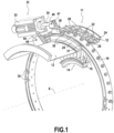
- a turbomachine 11 is partially shown and more particularly the casing 12 thereof housing at least one rotor wheel (not shown) and at least one stator stage 14 comprising a ring of variable-pitch blades 16. These blades are controlled by an actuating ring 18 coaxially surrounding the casing 12.
- the turbomachine is a compressor
- the casing houses several compression stages each comprising a rotor wheel and a stator stage 14 as shown. At least one and preferably several stator stages are, according to the invention, controlled independently of each other.
- the variable-pitch blades of the same stator stage are provided with pivots 22 passing through plain bearings 24 defined radially in the wall of the casing 12.
- each of these pivots is connected in an articulated manner by a connecting rod 26 to the same actuating ring 18 coaxially surrounding the casing.
- This ring is subject to moving according to a simple rotation centered on the axis X of the casing.
- the casing comprises sections of guide rail 28 extending annularly on either side of the edges of the ring 18.
- the latter carries grooved rollers 30 engaged with lateral ribs 31 of the rail.
- the actuating ring 18 is coupled to at least one adjacent specific drive unit 32, in the general shape of a jack, comprising two parts forming a body 33 and a rod 34. One of the parts is articulated to the casing 12 and the other part is articulated to a lateral extension 36 of said ring.
- the arrangement as defined above is sufficient to drive the ring 18 in rotation and consequently to modify the orientation of the fixed blades 16 of the stator stage.
- the or each actuating ring can advantageously be coupled to two aforementioned adjacent specific drive units, substantially diametrically opposed.
- the actuating crown 18 as shown may be provided with two diametrically opposed lateral extensions 36 and in this case, the casing carries two drive units arranged so as to combine their efforts to drive the crown 18 in rotation in one direction or the other.
- the actuator 32 in the general form of a jack is advantageously of the linear displacement electric motor type as defined above.
- the extension axis of the rod 34 of said motor unit forming a jack is located in a plane parallel to a median plane of the actuating ring 18. According to the example shown, the rod 34 is articulated to the ring 18 and the body 33 is articulated to the casing 13.
- the lateral extension 36 comprises a yoke 40 and the end of the rod comprises a flat part forming a connecting rod head, pierced, by which it is articulated to this yoke along an axis 41 parallel to the axis X of the casing.
- the body 33 comprises a lateral tab 44 articulated to a yoke 46 secured to the casing.
- the articulation between the body 33 and the casing 12 is arranged in the vicinity of the end of the body from which the rod 34 extends.
- the lateral tab 44 extends near the end of the body 33 from which the rod 34 emerges.
- the articulation between the body and the casing is located substantially in the middle of the actuator 32 when the rod is deployed to the maximum of its travel.
- This assembly ensures a minimum angular movement of the actuator 32 during the travel of the actuating ring, which makes it possible to house the actuator in a relatively restricted space around the casing.
Landscapes
- Engineering & Computer Science (AREA)
- Mechanical Engineering (AREA)
- General Engineering & Computer Science (AREA)
- Structures Of Non-Positive Displacement Pumps (AREA)
- Control Of Turbines (AREA)
- Supercharger (AREA)
- Turbine Rotor Nozzle Sealing (AREA)
Description
- L'invention se rapporte à une turbomachine comprenant un carter abritant au moins un étage statorique muni d'aubes à calage variable commandé par une couronne d'actionnement entourant coaxialement ledit carter et reliée par des biellettes auxdites aubes à calage variable. Elle concerne plus particulièrement la commande individualisée d'une telle couronne d'actionnement. L'invention s'applique notamment au domaine des réacteurs d'avions et plus particulièrement à un compresseur que comporte un tel réacteur.
- Dans une turbomachine du genre spécifié ci-dessus, un stator de compresseur est équipé d'au moins un étage d'aubes de redresseur, à calage variable, dont l'orientation dans la veine est ajustable. Ainsi, l'angle d'attaque des aubes peut être contrôlé en fonction des conditions de fonctionnement de l'avion, par un système d'asservissement qui commande le déplacement de ladite couronne.
- Sur les avions, les lois de variation des aubes à calage variable deviennent de plus en plus complexes, au point qu'il est de plus en plus souhaitable de pouvoir commander les aubes à calage variable, étage par étage. De ce fait, un actionnement par vérin commun associé à une cinématique de transmission complexe, coûteuse, encombrante et pesante est de moins en moins souhaitable.
- Le document
EP 527 593 - L'invention permet de résoudre tous ces problèmes.
- Plus particulièrement, l'invention concerne une turbomachine comprenant un carter abritant au moins un étage statorique muni d'aubes à calage variable commandées par une couronne d'actionnement entourant coaxialement ledit carter, assujettie à se déplacer selon une simple rotation centrée sur un axe dudit carter et reliée par des biellettes auxdites aubes à calage variable, ladite couronne d'actionnement est couplée à au moins une unité motrice spécifique adjacente, en forme générale de vérin, comprenant deux parties formant un corps et une tige, l'une des parties est articulée audit carter et l'autre partie est articulée à une extension latérale de ladite couronne, comme par exemple décrit dans le document
US 4 275 560 A . - Selon l'invention la tige est articulée à la couronne et le corps est articulé au dit carter, et l'articulation entre le corps et le carter est agencée au voisinage de l'extrémité du corps à partir de laquelle s'étend la tige.
- Par "unité motrice spécifique" on entend que chaque couronne d'actionnement est bien manoeuvrée indépendamment des autres si la turbomachine comporte plusieurs étages de stator équipés d'aubes à calage variable, ce qui est généralement le cas. Ce type de commande implique donc au moins une et de préférence deux unités motrices pour chaque couronne. Une telle unité motrice est compacte et placée au plus près de la couronne d'actionnement, ce qui simplifie et allège le système grâce à une liaison articulée directe entre la couronne et l'unité motrice. Il est plus facile de répartir autour du carter une pluralité d'unités motrices ayant chacune une puissance moyenne suffisante pour l'actionnement d'une seule couronne plutôt qu'une seule unité motrice de forte puissance et donc d'encombrement radial et de poids importants, reliée par un mécanisme compliqué aux différentes couronnes. En outre, comme mentionné plus haut, le fait de pouvoir manoeuvrer chaque couronne d'actionnement (donc chaque étage d'aubes à calage variable) indépendamment des autres est en soi avantageux pour une bonne maîtrise des conditions de fonctionnement du turboréacteur.
- De façon simple et avantageuse, l'axe d'extension de la tige de l'unité motrice formant vérin se situe dans un plan parallèle à un plan médian de ladite couronne d'actionnement. Par exemple, la tige est articulée à la couronne et le corps est articulé au carter.
- De façon simple, ladite extension latérale comporte une chape et une extrémité de la tige est articulée à cette chape selon un axe parallèle à l'axe du carter.
- De préférence, le corps comporte une patte latérale articulée à une chape solidaire dudit carter. Cependant, l'agencement inverse est également possible.
- Selon une caractéristique très avantageuse, l'actionneur est du type moteur électrique à déplacement linéaire. Le choix peut se porter sur des moteurs linéaires de type sans contact développés, par exemple, par la société "Copley Controls Corp". A titre d'exemple, un moteur référencé XTB3810 pourra être utilisé. Il bénéficie d'un encombrement réduit avec un corps de 122 mm de longueur pour une course de 75 mm environ.
- De préférence, la ou chaque couronne d'actionnement est couplée à deux unités motrices spécifiques adjacentes précitées, sensiblement diamétralement opposées.
- L'invention sera mieux comprise et d'autres avantages de celle-ci apparaîtront plus clairement à la lumière de la description qui va suivre d'une turbomachine conforme à son principe, donnée uniquement à titre d'exemple et faite en référence aux dessins annexés, dans lesquels :
- La figure unique représente partiellement et en perspective une turbomachine équipée d'un système de commande d'aubes à calage variable selon l'invention.
- En se reportant au dessin, on a représenté partiellement une turbomachine 11 et plus particulièrement le carter 12 de celle-ci abritant au moins une roue de rotor (non représentée) et au moins un étage statorique 14 comprenant une couronne d'aubes à calage variable 16. Ces aubes sont commandées par une couronne d'actionnement 18 entourant coaxialement le carter 12. En fait, si la turbomachine est un compresseur, le carter abrite plusieurs étages de compression comprenant chacun une roue de rotor et un étage statorique 14 tel que représenté. Au moins un et de préférence plusieurs étages statoriques sont, selon l'invention, commandés indépendamment les uns des autres. Pour ce faire, les aubes à calage variable d'un même étage statorique sont munies de pivots 22 traversant des paliers lisses 24 définis radialement dans la paroi du carter 12. Chacun de ces pivots est relié de façon articulée par une biellette 26 à une même couronne d'actionnement 18 entourant coaxialement le carter. Cette couronne est assujettie à se déplacer selon une simple rotation centrée sur l'axe X du carter. Pour ce faire, le carter comporte des tronçons de rail de guidage 28 s'étendant annulairement de part et d'autre des bords de la couronne 18. Cette dernière porte des galets à gorge 30 en prise avec des nervures latérales 31 du rail. L'agencement décrit ci-dessus est connu.
- Selon des caractéristiques importantes de l'invention, la couronne d'actionnement 18 est couplée à au moins une unité motrice spécifique 32 adjacente, en forme générale de vérin, comprenant deux parties formant un corps 33 et une tige 34. L'une des parties est articulée au carter 12 et l'autre partie est articulée à une extension latérale 36 de ladite couronne. L'agencement tel que défini ci-dessus est suffisant pour entraîner la couronne 18 en rotation et par conséquent pour modifier l'orientation des aubes fixes 16 de l'étage statorique. Cependant, pour des questions d'équilibrage et aussi pour utiliser des unités motrices moins encombrantes, la ou chaque couronne d'actionnement peut avantageusement être couplée à deux unités motrices spécifiques adjacentes précitées, sensiblement diamétralement opposées. Par exemple, la couronne d'actionnement 18 telle que représentée peut être munie de deux extensions latérales 36 diamétralement opposées et dans ce cas, le carter porte deux unités motrices agencées de façon à conjuguer leurs efforts pour entraîner la couronne 18 en rotation dans un sens ou dans l'autre.
- L'actionneur 32 en forme générale de vérin est avantageusement du type moteur électrique à déplacement linéaire comme défini plus haut. L'axe d'extension de la tige 34 de ladite unité motrice formant vérin se situe dans un plan parallèle à un plan médian de la couronne d'actionnement 18. Selon l'exemple représenté, la tige 34 est articulée à la couronne 18 et le corps 33 est articulé au carter 13.
- Plus précisément, l'extension latérale 36 comporte une chape 40 et l'extrémité de la tige comporte une partie plate formant tête de biellette, percée, par laquelle elle est articulée à cette chape selon un axe 41 parallèle à l'axe X du carter. Par ailleurs, le corps 33 comporte une patte latérale 44 articulée à une chape 46 solidaire du carter. Selon l'invention l'articulation entre le corps 33 et le carter 12 est agencée au voisinage de l'extrémité du corps à partir de laquelle s'étend la tige 34. Autrement dit, la patte latérale 44 s'étend près de l'extrémité du corps 33 d'où émerge la tige 34.
- Avantageusement, l'articulation entre le corps et le carter (éléments 46, 44) se situe sensiblement au milieu de l'actionneur 32 lorsque la tige est déployée au maximum de sa course. Ce montage assure un débattement angulaire minimum de l'actionneur 32 pendant la course de la couronne d'actionnement, ce qui permet de loger l'actionneur dans un espace relativement restreint autour du carter.
Claims (7)
- Turbomachine comprenant un carter (12) abritant au moins un étage statorique muni d'aubes à calage variable (16) commandées par une couronne d'actionnement (18) entourant coaxialement ledit carter, assujettie à se déplacer selon une simple rotation centrée sur un axe (X) dudit carter et reliée par des biellettes (26) auxdites aubes à calage variable, dans laquelle ladite couronne d'actionnement (18) est couplée à au moins une unité motrice spécifique (32) adjacente, en forme générale de vérin, comprenant deux parties formant un corps (33) et une tige (34),caractérisée en ce que ladite tige (34) est articulée à une extension latérale de la couronne (18) et ledit corps (33) est articulé audit carter (12), eten ce que l'articulation (44, 46) entre le corps et le carter est agencée au voisinage de l'extrémité du corps à partir de laquelle s'étend la tige.
- Turbomachine selon la revendication 1, caractérisée en ce que l'axe d'extension de la tige (34) de l'unité motrice formant vérin se situe dans un plan parallèle à un plan médian de ladite couronne d'actionnement.
- Turbomachine selon la revendication 1 ou 2, caractérisée en ce que ladite articulation se situe sensiblement au milieu dudit actionneur (32) lorsque ladite tige est déployée au maximum de sa course.
- Turbomachine selon l'une des revendications 1 à 3, caractérisée en ce que ladite extension latérale comporte une chape (40) et en ce que l'extrémité de ladite tige (34) est articulée à cette chape selon un axe (41) parallèle à l'axe dudit carter.
- Turbomachine selon l'une des revendications 1 à 4, caractérisée en ce que ledit corps (33) comporte une patte latérale (44) articulée à une chape (46) solidaire dudit carter.
- Turbomachine selon l'une des revendications précédentes, caractérisée en ce que ledit actionneur (32) est du type moteur électrique à déplacement linéaire.
- Turbomachine selon l'une des revendications précédentes, caractérisée en ce que la ou chaque couronne d'actionnement (18) est couplée à deux unités motrices (32) spécifiques adjacentes précitées, sensiblement diamétralement opposées.
Applications Claiming Priority (2)
| Application Number | Priority Date | Filing Date | Title |
|---|---|---|---|
| FR0958232A FR2952979B1 (fr) | 2009-11-20 | 2009-11-20 | Turbomachine comprenant un etage d'aubes de stator a calage variable et a commande independante. |
| PCT/FR2010/052453 WO2011061450A2 (fr) | 2009-11-20 | 2010-11-19 | Turbomachine comprenant un etage d'aubes de stator a calage variable et a commande independante |
Publications (3)
| Publication Number | Publication Date |
|---|---|
| EP2501941A2 EP2501941A2 (fr) | 2012-09-26 |
| EP2501941B1 EP2501941B1 (fr) | 2018-07-18 |
| EP2501941B2 true EP2501941B2 (fr) | 2024-10-30 |
Family
ID=42321186
Family Applications (1)
| Application Number | Title | Priority Date | Filing Date |
|---|---|---|---|
| EP10799084.8A Active EP2501941B2 (fr) | 2009-11-20 | 2010-11-19 | Turbomachine comprenant un étage d'aubes de stator à calage variable età commande indépendante |
Country Status (9)
| Country | Link |
|---|---|
| US (1) | US9429169B2 (fr) |
| EP (1) | EP2501941B2 (fr) |
| JP (1) | JP5951494B2 (fr) |
| CN (1) | CN102656371B (fr) |
| BR (1) | BR112012012124B1 (fr) |
| CA (1) | CA2781306C (fr) |
| FR (1) | FR2952979B1 (fr) |
| RU (1) | RU2562895C2 (fr) |
| WO (1) | WO2011061450A2 (fr) |
Families Citing this family (15)
| Publication number | Priority date | Publication date | Assignee | Title |
|---|---|---|---|---|
| US8909454B2 (en) * | 2011-04-08 | 2014-12-09 | General Electric Company | Control of compression system with independently actuated inlet guide and/or stator vanes |
| US20140205424A1 (en) * | 2012-08-29 | 2014-07-24 | General Electric Company | Systems and Methods to Control Variable Stator Vanes in Gas Turbine Engines |
| DE102012019950A1 (de) | 2012-10-11 | 2014-04-17 | Man Diesel & Turbo Se | Vorrichtung zum Verändern des Leitschaufelwinkels bei axialen Strömungsmaschinen |
| EP2956631B1 (fr) * | 2013-02-12 | 2020-04-15 | United Technologies Corporation | Système de réglage d'aubes variable |
| WO2014189568A2 (fr) * | 2013-03-13 | 2014-11-27 | United Technologies Corporation | Système d'entraînement d'aubes variables |
| US9429033B2 (en) * | 2013-11-08 | 2016-08-30 | Honeywell International Inc. | Drive arrangement for a unison ring of a variable-vane assembly |
| FR3014152B1 (fr) * | 2013-11-29 | 2015-12-25 | Snecma | Dispositif de guidage d'aubes de redresseur a angle de calage variable de turbomachine et procede d'assemblage d'un tel dispositif |
| GB201409449D0 (en) | 2014-05-28 | 2014-07-09 | Rolls Royce Deutschland | A variable stator vane arrangment |
| US10697241B2 (en) | 2015-10-28 | 2020-06-30 | Halliburton Energy Services, Inc. | Downhole turbine with an adjustable shroud |
| US10704411B2 (en) | 2018-08-03 | 2020-07-07 | General Electric Company | Variable vane actuation system for a turbo machine |
| RU2696839C1 (ru) * | 2018-10-10 | 2019-08-06 | Публичное акционерное общество "ОДК-Уфимское моторостроительное производственное объединение" (ПАО "ОДК-УМПО") | Компрессор двухконтурного газотурбинного двигателя |
| FR3090030B1 (fr) * | 2018-12-12 | 2020-11-20 | Safran Aircraft Engines | Dispositif de maintien pour le démontage d’une roue à aubes de turbomachine et procédé l’utilisant |
| US12000292B1 (en) * | 2022-12-30 | 2024-06-04 | Rolls-Royce North American Technologies Inc. | Systems and methods for multi-dimensional variable vane stage rigging |
| US11982193B1 (en) * | 2022-12-30 | 2024-05-14 | Rolls-Royce North American Technologies Inc. | Systems and methods for multi-dimensional variable vane stage rigging utilizing adjustable inclined mechanisms |
| US12000293B1 (en) * | 2022-12-30 | 2024-06-04 | Rolls-Royce North American Technologies Inc. | Systems and methods for multi-dimensional variable vane stage rigging utilizing coupling mechanisms |
Citations (1)
| Publication number | Priority date | Publication date | Assignee | Title |
|---|---|---|---|---|
| US20090116954A1 (en) † | 2007-10-12 | 2009-05-07 | Snecma | Pitch control ring for stator vanes of a turbomachine |
Family Cites Families (13)
| Publication number | Priority date | Publication date | Assignee | Title |
|---|---|---|---|---|
| US3861822A (en) * | 1974-02-27 | 1975-01-21 | Gen Electric | Duct with vanes having selectively variable pitch |
| US3958896A (en) * | 1974-12-02 | 1976-05-25 | Vitaly Viktorovich Vikhirev | Hydraulic machine |
| US4275560A (en) | 1978-12-27 | 1981-06-30 | General Electric Company | Blocker door actuation system |
| JPS5862303A (ja) | 1981-10-09 | 1983-04-13 | Hitachi Ltd | 軸流式流体機械の静翼可変装置 |
| US4979874A (en) * | 1989-06-19 | 1990-12-25 | United Technologies Corporation | Variable van drive mechanism |
| JPH03102098U (fr) * | 1990-02-05 | 1991-10-24 | ||
| JPH05199704A (ja) * | 1991-08-08 | 1993-08-06 | General Electric Co <Ge> | 電気アクチュエータ・モータ |
| JPH0658173U (ja) | 1993-01-21 | 1994-08-12 | 東芝エンジニアリング株式会社 | 可変ピッチプロペラの駆動装置 |
| UA17443A (uk) * | 1995-09-04 | 1997-05-06 | Мехаhізм повороту лопаток статора осьової турбомашиhи | |
| US6821084B2 (en) | 2002-12-11 | 2004-11-23 | General Electric Company | Torque tube bearing assembly |
| FR2881190A1 (fr) * | 2005-01-21 | 2006-07-28 | Snecma Moteurs Sa | Dispositif d'actionnement pour redresseurs a calage variable, et moteur d'aeronef equipe d'un tel dispositif |
| US20100260591A1 (en) * | 2007-06-08 | 2010-10-14 | General Electric Company | Spanwise split variable guide vane and related method |
| FR2928979B1 (fr) * | 2008-03-19 | 2015-05-01 | Snecma | Dispositif de commande d'aubes a calage variable dans une turbomachine. |
-
2009
- 2009-11-20 FR FR0958232A patent/FR2952979B1/fr active Active
-
2010
- 2010-11-19 CA CA2781306A patent/CA2781306C/fr active Active
- 2010-11-19 RU RU2012125633/06A patent/RU2562895C2/ru active
- 2010-11-19 JP JP2012539389A patent/JP5951494B2/ja active Active
- 2010-11-19 CN CN201080052728.9A patent/CN102656371B/zh active Active
- 2010-11-19 US US13/511,068 patent/US9429169B2/en active Active
- 2010-11-19 BR BR112012012124-3A patent/BR112012012124B1/pt active IP Right Grant
- 2010-11-19 WO PCT/FR2010/052453 patent/WO2011061450A2/fr not_active Ceased
- 2010-11-19 EP EP10799084.8A patent/EP2501941B2/fr active Active
Patent Citations (1)
| Publication number | Priority date | Publication date | Assignee | Title |
|---|---|---|---|---|
| US20090116954A1 (en) † | 2007-10-12 | 2009-05-07 | Snecma | Pitch control ring for stator vanes of a turbomachine |
Also Published As
| Publication number | Publication date |
|---|---|
| JP5951494B2 (ja) | 2016-07-13 |
| JP2013511646A (ja) | 2013-04-04 |
| CA2781306A1 (fr) | 2011-05-26 |
| EP2501941A2 (fr) | 2012-09-26 |
| FR2952979B1 (fr) | 2012-01-20 |
| CN102656371B (zh) | 2016-03-16 |
| US9429169B2 (en) | 2016-08-30 |
| RU2562895C2 (ru) | 2015-09-10 |
| FR2952979A1 (fr) | 2011-05-27 |
| RU2012125633A (ru) | 2013-12-27 |
| EP2501941B1 (fr) | 2018-07-18 |
| BR112012012124A2 (pt) | 2016-04-12 |
| CN102656371A (zh) | 2012-09-05 |
| BR112012012124B1 (pt) | 2020-11-24 |
| CA2781306C (fr) | 2018-01-16 |
| US20130028716A1 (en) | 2013-01-31 |
| WO2011061450A2 (fr) | 2011-05-26 |
| WO2011061450A3 (fr) | 2011-09-29 |
Similar Documents
| Publication | Publication Date | Title |
|---|---|---|
| EP2501941B2 (fr) | Turbomachine comprenant un étage d'aubes de stator à calage variable età commande indépendante | |
| EP2435303B1 (fr) | Dispositif a verin mobile pour la commande de l'orientation des pales de soufflante d'un turbopropulseur. | |
| EP2435304B1 (fr) | Dispositif pour la commande de l'orientation des pales de soufflante d'un turbopropulseur | |
| EP2435302B1 (fr) | Dispositif a verin fixe pour la commande de l'orientation des pales de soufflante d'un turbopropulseur | |
| CA2495992C (fr) | Adaptation aerodynamique de la soufflante arriere d'un turboreacteur double soufflante | |
| CA2547026C (fr) | Systeme de commande d'etages d'aubes de stator a angle de calage variable de turbomachine | |
| EP0636766B1 (fr) | Stator de turbomachine à aubes pivotantes et anneau de commande | |
| FR2937678A1 (fr) | Dispositif de commande de l'orientation des pales de soufflante d'un turbopropulseur | |
| CA2610056C (fr) | Turbopropulseur comportant un ensemble de pales a orientation reglable | |
| EP1672180B1 (fr) | Etage d'aubes de redresseur actionnées par une couronne rotative déplacée par des moyens moteurs électriques | |
| FR3055001A1 (fr) | Systeme de changement de pas equipe de moyens de reglage du pas des pales et turbomachine correspondante | |
| FR3036093A1 (fr) | Dispositif a bras de levier pour la commande de l'orientation des pales de soufflante d'une turbomachine a soufflante non carenee | |
| CA2854991A1 (fr) | Systeme mecanique tournant a actionnement sans contact | |
| FR3036141A1 (fr) | Arbre de commande radial pour dispositif de commande de l'orientation des pales de soufflante d'une turbomachine a soufflante non carenee et procede de montage d'un tel arbre. | |
| EP4380858A1 (fr) | Module de soufflante a pales a calage variable | |
| FR3126018A1 (fr) | Systeme de changement de pas des pales d’une soufflante d’un ensemble propulsif | |
| FR3027072A1 (fr) | Anneau de commande d'un etage d'aubes a calage variable pour une turbomachine | |
| FR3123884A1 (fr) | Systeme de changement de pas des pales d’une helice d’une turbomachine | |
| FR3030649A1 (fr) | Mecanisme d'entrainement d'organes de reglage de l'orientation des pales | |
| WO2016181051A1 (fr) | Dispositif a arbre radial pour la commande de l'orientation des pales de soufflante d'une turbomachine a soufflante non carenee | |
| EP2982596B1 (fr) | Dispositif de propulsion, notamment pour un véhicule marin, comportant au moins une hélice à pales orientables | |
| FR3125505A1 (fr) | Systeme de changement de pas des pales d’une helice d’une turbomachine |
Legal Events
| Date | Code | Title | Description |
|---|---|---|---|
| PUAI | Public reference made under article 153(3) epc to a published international application that has entered the european phase |
Free format text: ORIGINAL CODE: 0009012 |
|
| 17P | Request for examination filed |
Effective date: 20120611 |
|
| AK | Designated contracting states |
Kind code of ref document: A2 Designated state(s): AL AT BE BG CH CY CZ DE DK EE ES FI FR GB GR HR HU IE IS IT LI LT LU LV MC MK MT NL NO PL PT RO RS SE SI SK SM TR |
|
| DAX | Request for extension of the european patent (deleted) | ||
| 17Q | First examination report despatched |
Effective date: 20160802 |
|
| GRAP | Despatch of communication of intention to grant a patent |
Free format text: ORIGINAL CODE: EPIDOSNIGR1 |
|
| STAA | Information on the status of an ep patent application or granted ep patent |
Free format text: STATUS: GRANT OF PATENT IS INTENDED |
|
| INTG | Intention to grant announced |
Effective date: 20180327 |
|
| GRAS | Grant fee paid |
Free format text: ORIGINAL CODE: EPIDOSNIGR3 |
|
| GRAA | (expected) grant |
Free format text: ORIGINAL CODE: 0009210 |
|
| STAA | Information on the status of an ep patent application or granted ep patent |
Free format text: STATUS: THE PATENT HAS BEEN GRANTED |
|
| RAP1 | Party data changed (applicant data changed or rights of an application transferred) |
Owner name: SAFRAN AIRCRAFT ENGINES |
|
| AK | Designated contracting states |
Kind code of ref document: B1 Designated state(s): AL AT BE BG CH CY CZ DE DK EE ES FI FR GB GR HR HU IE IS IT LI LT LU LV MC MK MT NL NO PL PT RO RS SE SI SK SM TR |
|
| REG | Reference to a national code |
Ref country code: GB Ref legal event code: FG4D Free format text: NOT ENGLISH |
|
| REG | Reference to a national code |
Ref country code: CH Ref legal event code: EP |
|
| REG | Reference to a national code |
Ref country code: IE Ref legal event code: FG4D Free format text: LANGUAGE OF EP DOCUMENT: FRENCH |
|
| REG | Reference to a national code |
Ref country code: AT Ref legal event code: REF Ref document number: 1019672 Country of ref document: AT Kind code of ref document: T Effective date: 20180815 |
|
| REG | Reference to a national code |
Ref country code: DE Ref legal event code: R096 Ref document number: 602010052045 Country of ref document: DE |
|
| REG | Reference to a national code |
Ref country code: SE Ref legal event code: TRGR |
|
| REG | Reference to a national code |
Ref country code: FR Ref legal event code: PLFP Year of fee payment: 9 |
|
| REG | Reference to a national code |
Ref country code: NL Ref legal event code: MP Effective date: 20180718 |
|
| REG | Reference to a national code |
Ref country code: LT Ref legal event code: MG4D |
|
| REG | Reference to a national code |
Ref country code: AT Ref legal event code: MK05 Ref document number: 1019672 Country of ref document: AT Kind code of ref document: T Effective date: 20180718 |
|
| PG25 | Lapsed in a contracting state [announced via postgrant information from national office to epo] |
Ref country code: NL Free format text: LAPSE BECAUSE OF FAILURE TO SUBMIT A TRANSLATION OF THE DESCRIPTION OR TO PAY THE FEE WITHIN THE PRESCRIBED TIME-LIMIT Effective date: 20180718 |
|
| PG25 | Lapsed in a contracting state [announced via postgrant information from national office to epo] |
Ref country code: NO Free format text: LAPSE BECAUSE OF FAILURE TO SUBMIT A TRANSLATION OF THE DESCRIPTION OR TO PAY THE FEE WITHIN THE PRESCRIBED TIME-LIMIT Effective date: 20181018 Ref country code: GR Free format text: LAPSE BECAUSE OF FAILURE TO SUBMIT A TRANSLATION OF THE DESCRIPTION OR TO PAY THE FEE WITHIN THE PRESCRIBED TIME-LIMIT Effective date: 20181019 Ref country code: FI Free format text: LAPSE BECAUSE OF FAILURE TO SUBMIT A TRANSLATION OF THE DESCRIPTION OR TO PAY THE FEE WITHIN THE PRESCRIBED TIME-LIMIT Effective date: 20180718 Ref country code: RS Free format text: LAPSE BECAUSE OF FAILURE TO SUBMIT A TRANSLATION OF THE DESCRIPTION OR TO PAY THE FEE WITHIN THE PRESCRIBED TIME-LIMIT Effective date: 20180718 Ref country code: IS Free format text: LAPSE BECAUSE OF FAILURE TO SUBMIT A TRANSLATION OF THE DESCRIPTION OR TO PAY THE FEE WITHIN THE PRESCRIBED TIME-LIMIT Effective date: 20181118 Ref country code: PL Free format text: LAPSE BECAUSE OF FAILURE TO SUBMIT A TRANSLATION OF THE DESCRIPTION OR TO PAY THE FEE WITHIN THE PRESCRIBED TIME-LIMIT Effective date: 20180718 Ref country code: AT Free format text: LAPSE BECAUSE OF FAILURE TO SUBMIT A TRANSLATION OF THE DESCRIPTION OR TO PAY THE FEE WITHIN THE PRESCRIBED TIME-LIMIT Effective date: 20180718 Ref country code: BG Free format text: LAPSE BECAUSE OF FAILURE TO SUBMIT A TRANSLATION OF THE DESCRIPTION OR TO PAY THE FEE WITHIN THE PRESCRIBED TIME-LIMIT Effective date: 20181018 Ref country code: LT Free format text: LAPSE BECAUSE OF FAILURE TO SUBMIT A TRANSLATION OF THE DESCRIPTION OR TO PAY THE FEE WITHIN THE PRESCRIBED TIME-LIMIT Effective date: 20180718 |
|
| PG25 | Lapsed in a contracting state [announced via postgrant information from national office to epo] |
Ref country code: AL Free format text: LAPSE BECAUSE OF FAILURE TO SUBMIT A TRANSLATION OF THE DESCRIPTION OR TO PAY THE FEE WITHIN THE PRESCRIBED TIME-LIMIT Effective date: 20180718 Ref country code: LV Free format text: LAPSE BECAUSE OF FAILURE TO SUBMIT A TRANSLATION OF THE DESCRIPTION OR TO PAY THE FEE WITHIN THE PRESCRIBED TIME-LIMIT Effective date: 20180718 Ref country code: HR Free format text: LAPSE BECAUSE OF FAILURE TO SUBMIT A TRANSLATION OF THE DESCRIPTION OR TO PAY THE FEE WITHIN THE PRESCRIBED TIME-LIMIT Effective date: 20180718 |
|
| REG | Reference to a national code |
Ref country code: DE Ref legal event code: R026 Ref document number: 602010052045 Country of ref document: DE |
|
| PLBI | Opposition filed |
Free format text: ORIGINAL CODE: 0009260 |
|
| PG25 | Lapsed in a contracting state [announced via postgrant information from national office to epo] |
Ref country code: EE Free format text: LAPSE BECAUSE OF FAILURE TO SUBMIT A TRANSLATION OF THE DESCRIPTION OR TO PAY THE FEE WITHIN THE PRESCRIBED TIME-LIMIT Effective date: 20180718 Ref country code: ES Free format text: LAPSE BECAUSE OF FAILURE TO SUBMIT A TRANSLATION OF THE DESCRIPTION OR TO PAY THE FEE WITHIN THE PRESCRIBED TIME-LIMIT Effective date: 20180718 Ref country code: CZ Free format text: LAPSE BECAUSE OF FAILURE TO SUBMIT A TRANSLATION OF THE DESCRIPTION OR TO PAY THE FEE WITHIN THE PRESCRIBED TIME-LIMIT Effective date: 20180718 Ref country code: RO Free format text: LAPSE BECAUSE OF FAILURE TO SUBMIT A TRANSLATION OF THE DESCRIPTION OR TO PAY THE FEE WITHIN THE PRESCRIBED TIME-LIMIT Effective date: 20180718 |
|
| PLAX | Notice of opposition and request to file observation + time limit sent |
Free format text: ORIGINAL CODE: EPIDOSNOBS2 |
|
| 26 | Opposition filed |
Opponent name: UNITED TECHNOLOGIES CORPORATION Effective date: 20190418 |
|
| PG25 | Lapsed in a contracting state [announced via postgrant information from national office to epo] |
Ref country code: SK Free format text: LAPSE BECAUSE OF FAILURE TO SUBMIT A TRANSLATION OF THE DESCRIPTION OR TO PAY THE FEE WITHIN THE PRESCRIBED TIME-LIMIT Effective date: 20180718 Ref country code: SM Free format text: LAPSE BECAUSE OF FAILURE TO SUBMIT A TRANSLATION OF THE DESCRIPTION OR TO PAY THE FEE WITHIN THE PRESCRIBED TIME-LIMIT Effective date: 20180718 Ref country code: DK Free format text: LAPSE BECAUSE OF FAILURE TO SUBMIT A TRANSLATION OF THE DESCRIPTION OR TO PAY THE FEE WITHIN THE PRESCRIBED TIME-LIMIT Effective date: 20180718 |
|
| REG | Reference to a national code |
Ref country code: CH Ref legal event code: PL |
|
| PG25 | Lapsed in a contracting state [announced via postgrant information from national office to epo] |
Ref country code: MC Free format text: LAPSE BECAUSE OF FAILURE TO SUBMIT A TRANSLATION OF THE DESCRIPTION OR TO PAY THE FEE WITHIN THE PRESCRIBED TIME-LIMIT Effective date: 20180718 Ref country code: LU Free format text: LAPSE BECAUSE OF NON-PAYMENT OF DUE FEES Effective date: 20181119 |
|
| REG | Reference to a national code |
Ref country code: BE Ref legal event code: MM Effective date: 20181130 |
|
| REG | Reference to a national code |
Ref country code: IE Ref legal event code: MM4A |
|
| PG25 | Lapsed in a contracting state [announced via postgrant information from national office to epo] |
Ref country code: CH Free format text: LAPSE BECAUSE OF NON-PAYMENT OF DUE FEES Effective date: 20181130 Ref country code: SI Free format text: LAPSE BECAUSE OF FAILURE TO SUBMIT A TRANSLATION OF THE DESCRIPTION OR TO PAY THE FEE WITHIN THE PRESCRIBED TIME-LIMIT Effective date: 20180718 Ref country code: LI Free format text: LAPSE BECAUSE OF NON-PAYMENT OF DUE FEES Effective date: 20181130 |
|
| PLBB | Reply of patent proprietor to notice(s) of opposition received |
Free format text: ORIGINAL CODE: EPIDOSNOBS3 |
|
| PG25 | Lapsed in a contracting state [announced via postgrant information from national office to epo] |
Ref country code: IE Free format text: LAPSE BECAUSE OF NON-PAYMENT OF DUE FEES Effective date: 20181119 |
|
| PG25 | Lapsed in a contracting state [announced via postgrant information from national office to epo] |
Ref country code: BE Free format text: LAPSE BECAUSE OF NON-PAYMENT OF DUE FEES Effective date: 20181130 |
|
| PG25 | Lapsed in a contracting state [announced via postgrant information from national office to epo] |
Ref country code: MT Free format text: LAPSE BECAUSE OF FAILURE TO SUBMIT A TRANSLATION OF THE DESCRIPTION OR TO PAY THE FEE WITHIN THE PRESCRIBED TIME-LIMIT Effective date: 20180718 |
|
| PG25 | Lapsed in a contracting state [announced via postgrant information from national office to epo] |
Ref country code: TR Free format text: LAPSE BECAUSE OF FAILURE TO SUBMIT A TRANSLATION OF THE DESCRIPTION OR TO PAY THE FEE WITHIN THE PRESCRIBED TIME-LIMIT Effective date: 20180718 |
|
| PG25 | Lapsed in a contracting state [announced via postgrant information from national office to epo] |
Ref country code: PT Free format text: LAPSE BECAUSE OF FAILURE TO SUBMIT A TRANSLATION OF THE DESCRIPTION OR TO PAY THE FEE WITHIN THE PRESCRIBED TIME-LIMIT Effective date: 20180718 |
|
| PG25 | Lapsed in a contracting state [announced via postgrant information from national office to epo] |
Ref country code: HU Free format text: LAPSE BECAUSE OF FAILURE TO SUBMIT A TRANSLATION OF THE DESCRIPTION OR TO PAY THE FEE WITHIN THE PRESCRIBED TIME-LIMIT; INVALID AB INITIO Effective date: 20101119 Ref country code: CY Free format text: LAPSE BECAUSE OF FAILURE TO SUBMIT A TRANSLATION OF THE DESCRIPTION OR TO PAY THE FEE WITHIN THE PRESCRIBED TIME-LIMIT Effective date: 20180718 Ref country code: MK Free format text: LAPSE BECAUSE OF NON-PAYMENT OF DUE FEES Effective date: 20180718 |
|
| PLAB | Opposition data, opponent's data or that of the opponent's representative modified |
Free format text: ORIGINAL CODE: 0009299OPPO |
|
| R26 | Opposition filed (corrected) |
Opponent name: RAYTHEON TECHNOLOGIES CORPORATION Effective date: 20190418 |
|
| APAH | Appeal reference modified |
Free format text: ORIGINAL CODE: EPIDOSCREFNO |
|
| APBM | Appeal reference recorded |
Free format text: ORIGINAL CODE: EPIDOSNREFNO |
|
| APBP | Date of receipt of notice of appeal recorded |
Free format text: ORIGINAL CODE: EPIDOSNNOA2O |
|
| APBQ | Date of receipt of statement of grounds of appeal recorded |
Free format text: ORIGINAL CODE: EPIDOSNNOA3O |
|
| APBU | Appeal procedure closed |
Free format text: ORIGINAL CODE: EPIDOSNNOA9O |
|
| PUAH | Patent maintained in amended form |
Free format text: ORIGINAL CODE: 0009272 |
|
| STAA | Information on the status of an ep patent application or granted ep patent |
Free format text: STATUS: PATENT MAINTAINED AS AMENDED |
|
| 27A | Patent maintained in amended form |
Effective date: 20241030 |
|
| AK | Designated contracting states |
Kind code of ref document: B2 Designated state(s): AL AT BE BG CH CY CZ DE DK EE ES FI FR GB GR HR HU IE IS IT LI LT LU LV MC MK MT NL NO PL PT RO RS SE SI SK SM TR |
|
| REG | Reference to a national code |
Ref country code: DE Ref legal event code: R102 Ref document number: 602010052045 Country of ref document: DE |
|
| REG | Reference to a national code |
Ref country code: SE Ref legal event code: RPEO |
|
| PGFP | Annual fee paid to national office [announced via postgrant information from national office to epo] |
Ref country code: DE Payment date: 20251118 Year of fee payment: 16 |
|
| PGFP | Annual fee paid to national office [announced via postgrant information from national office to epo] |
Ref country code: GB Payment date: 20251125 Year of fee payment: 16 |
|
| PGFP | Annual fee paid to national office [announced via postgrant information from national office to epo] |
Ref country code: IT Payment date: 20251128 Year of fee payment: 16 |
|
| PGFP | Annual fee paid to national office [announced via postgrant information from national office to epo] |
Ref country code: FR Payment date: 20251125 Year of fee payment: 16 |
|
| PGFP | Annual fee paid to national office [announced via postgrant information from national office to epo] |
Ref country code: SE Payment date: 20251119 Year of fee payment: 16 |