EP2501941B2 - Turbinenmotor mit einer stufe mit verstellleitschaufeln mit unabhängiger steuerung - Google Patents
Turbinenmotor mit einer stufe mit verstellleitschaufeln mit unabhängiger steuerung Download PDFInfo
- Publication number
- EP2501941B2 EP2501941B2 EP10799084.8A EP10799084A EP2501941B2 EP 2501941 B2 EP2501941 B2 EP 2501941B2 EP 10799084 A EP10799084 A EP 10799084A EP 2501941 B2 EP2501941 B2 EP 2501941B2
- Authority
- EP
- European Patent Office
- Prior art keywords
- casing
- turbine engine
- actuator
- rod
- ring
- Prior art date
- Legal status (The legal status is an assumption and is not a legal conclusion. Google has not performed a legal analysis and makes no representation as to the accuracy of the status listed.)
- Active
Links
- YSSSPARMOAYJTE-UHFFFAOYSA-N dibenzo-18-crown-6 Chemical compound O1CCOCCOC2=CC=CC=C2OCCOCCOC2=CC=CC=C21 YSSSPARMOAYJTE-UHFFFAOYSA-N 0.000 description 2
- 238000006073 displacement reaction Methods 0.000 description 2
- 230000006698 induction Effects 0.000 description 2
- 230000005540 biological transmission Effects 0.000 description 1
- 230000006835 compression Effects 0.000 description 1
- 238000007906 compression Methods 0.000 description 1
Images
Classifications
-
- F—MECHANICAL ENGINEERING; LIGHTING; HEATING; WEAPONS; BLASTING
- F04—POSITIVE - DISPLACEMENT MACHINES FOR LIQUIDS; PUMPS FOR LIQUIDS OR ELASTIC FLUIDS
- F04D—NON-POSITIVE-DISPLACEMENT PUMPS
- F04D29/00—Details, component parts, or accessories
- F04D29/40—Casings; Connections of working fluid
- F04D29/52—Casings; Connections of working fluid for axial pumps
- F04D29/54—Fluid-guiding means, e.g. diffusers
- F04D29/56—Fluid-guiding means, e.g. diffusers adjustable
- F04D29/563—Fluid-guiding means, e.g. diffusers adjustable specially adapted for elastic fluid pumps
-
- F—MECHANICAL ENGINEERING; LIGHTING; HEATING; WEAPONS; BLASTING
- F01—MACHINES OR ENGINES IN GENERAL; ENGINE PLANTS IN GENERAL; STEAM ENGINES
- F01D—NON-POSITIVE DISPLACEMENT MACHINES OR ENGINES, e.g. STEAM TURBINES
- F01D17/00—Regulating or controlling by varying flow
- F01D17/10—Final actuators
- F01D17/12—Final actuators arranged in stator parts
- F01D17/14—Final actuators arranged in stator parts varying effective cross-sectional area of nozzles or guide conduits
- F01D17/16—Final actuators arranged in stator parts varying effective cross-sectional area of nozzles or guide conduits by means of nozzle vanes
- F01D17/162—Final actuators arranged in stator parts varying effective cross-sectional area of nozzles or guide conduits by means of nozzle vanes for axial flow, i.e. the vanes turning around axes which are essentially perpendicular to the rotor centre line
-
- F—MECHANICAL ENGINEERING; LIGHTING; HEATING; WEAPONS; BLASTING
- F05—INDEXING SCHEMES RELATING TO ENGINES OR PUMPS IN VARIOUS SUBCLASSES OF CLASSES F01-F04
- F05D—INDEXING SCHEME FOR ASPECTS RELATING TO NON-POSITIVE-DISPLACEMENT MACHINES OR ENGINES, GAS-TURBINES OR JET-PROPULSION PLANTS
- F05D2260/00—Function
- F05D2260/50—Kinematic linkage, i.e. transmission of position
-
- F—MECHANICAL ENGINEERING; LIGHTING; HEATING; WEAPONS; BLASTING
- F05—INDEXING SCHEMES RELATING TO ENGINES OR PUMPS IN VARIOUS SUBCLASSES OF CLASSES F01-F04
- F05D—INDEXING SCHEME FOR ASPECTS RELATING TO NON-POSITIVE-DISPLACEMENT MACHINES OR ENGINES, GAS-TURBINES OR JET-PROPULSION PLANTS
- F05D2270/00—Control
- F05D2270/60—Control system actuates means
- F05D2270/62—Electrical actuators
-
- Y—GENERAL TAGGING OF NEW TECHNOLOGICAL DEVELOPMENTS; GENERAL TAGGING OF CROSS-SECTIONAL TECHNOLOGIES SPANNING OVER SEVERAL SECTIONS OF THE IPC; TECHNICAL SUBJECTS COVERED BY FORMER USPC CROSS-REFERENCE ART COLLECTIONS [XRACs] AND DIGESTS
- Y02—TECHNOLOGIES OR APPLICATIONS FOR MITIGATION OR ADAPTATION AGAINST CLIMATE CHANGE
- Y02T—CLIMATE CHANGE MITIGATION TECHNOLOGIES RELATED TO TRANSPORTATION
- Y02T50/00—Aeronautics or air transport
- Y02T50/60—Efficient propulsion technologies, e.g. for aircraft
Definitions
- the invention relates to a turbomachine comprising a casing housing at least one stator stage provided with variable-pitch blades controlled by an actuating ring coaxially surrounding said casing and connected by connecting rods to said variable-pitch blades. It relates more particularly to the individualized control of such an actuating ring.
- the invention applies in particular to the field of aircraft engines and more particularly to a compressor that such a reactor comprises.
- a compressor stator is equipped with at least one stage of variable-pitch rectifier vanes, the orientation of which in the flow path is adjustable.
- the angle of attack of the vanes can be controlled according to the operating conditions of the aircraft, by a servo system which controls the movement of said crown.
- variable pitch blades On aircraft, the variation laws of variable pitch blades are becoming more and more complex, to the point that it is increasingly desirable to be able to control the variable pitch blades, stage by stage. As a result, a common cylinder actuation associated with complex, expensive, bulky and heavy transmission kinematics is increasingly less desirable.
- the document EP 527 593 describes a linear electric motor structure suitable for operating an actuator ring.
- the system described uses electrical induction elements located radially outside the actuator ring. These induction elements are bulky and difficult to integrate into the space available inside the housing.
- the actuator ring is not satisfactorily centered, especially if one considers possible variations in diameter (due to the temperature rise) between the ring and the housing that supports it.
- the invention solves all these problems.
- the invention relates to a turbomachine comprising a casing housing at least one stator stage provided with variable-pitch blades controlled by an actuating ring coaxially surrounding said casing, subject to moving according to a simple rotation centered on an axis of said casing and connected by connecting rods to said variable-pitch blades, said actuating ring is coupled to at least one adjacent specific drive unit, in the general shape of a jack, comprising two parts forming a body and a rod, one of the parts is articulated to said casing and the other part is articulated to a lateral extension of said ring, as for example described in the document US 4,275,560 A .
- the rod is articulated to the crown and the body is articulated to said casing, and the articulation between the body and the casing is arranged in the vicinity of the end of the body from which the rod extends.
- each actuating ring is well maneuvered independently of the others if the turbomachine comprises several stator stages equipped with variable-pitch vanes, which is generally the case.
- This type of control therefore involves at least one and preferably two drive units for each ring.
- Such a drive unit is compact and placed as close as possible to the actuating ring, which simplifies and lightens the system thanks to a direct articulated connection between the ring and the drive unit. It is easier to distribute around the casing a plurality of drive units each having an average power sufficient for the actuation of a single ring rather than a single drive unit of high power and therefore of significant radial size and weight, connected by a complicated mechanism to the different rings.
- the fact of being able to maneuver each actuating ring (therefore each stage of variable-pitch vanes) independently of the others is in itself advantageous for good control of the operating conditions of the turbojet.
- the extension axis of the rod of the drive unit forming a cylinder is located in a plane parallel to a median plane of said actuating crown.
- the rod is articulated to the crown and the body is articulated to the casing.
- said lateral extension comprises a yoke and one end of the rod is articulated to this yoke along an axis parallel to the axis of the casing.
- the body comprises a side tab articulated to a yoke secured to said housing.
- the reverse arrangement is also possible.
- the actuator is of the linear displacement electric motor type.
- the choice can be made on contactless linear motors developed, for example, by the company "Copley Controls Corp".
- a motor referenced XTB3810 can be used. It benefits from a reduced size with a body of 122 mm in length for a stroke of approximately 75 mm.
- the or each actuating ring is coupled to two aforementioned adjacent specific motor units, substantially diametrically opposed.
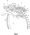
- a turbomachine 11 is partially shown and more particularly the casing 12 thereof housing at least one rotor wheel (not shown) and at least one stator stage 14 comprising a ring of variable-pitch blades 16. These blades are controlled by an actuating ring 18 coaxially surrounding the casing 12.
- the turbomachine is a compressor
- the casing houses several compression stages each comprising a rotor wheel and a stator stage 14 as shown. At least one and preferably several stator stages are, according to the invention, controlled independently of each other.
- the variable-pitch blades of the same stator stage are provided with pivots 22 passing through plain bearings 24 defined radially in the wall of the casing 12.
- each of these pivots is connected in an articulated manner by a connecting rod 26 to the same actuating ring 18 coaxially surrounding the casing.
- This ring is subject to moving according to a simple rotation centered on the axis X of the casing.
- the casing comprises sections of guide rail 28 extending annularly on either side of the edges of the ring 18.
- the latter carries grooved rollers 30 engaged with lateral ribs 31 of the rail.
- the actuating ring 18 is coupled to at least one adjacent specific drive unit 32, in the general shape of a jack, comprising two parts forming a body 33 and a rod 34. One of the parts is articulated to the casing 12 and the other part is articulated to a lateral extension 36 of said ring.
- the arrangement as defined above is sufficient to drive the ring 18 in rotation and consequently to modify the orientation of the fixed blades 16 of the stator stage.
- the or each actuating ring can advantageously be coupled to two aforementioned adjacent specific drive units, substantially diametrically opposed.
- the actuating crown 18 as shown may be provided with two diametrically opposed lateral extensions 36 and in this case, the casing carries two drive units arranged so as to combine their efforts to drive the crown 18 in rotation in one direction or the other.
- the actuator 32 in the general form of a jack is advantageously of the linear displacement electric motor type as defined above.
- the extension axis of the rod 34 of said motor unit forming a jack is located in a plane parallel to a median plane of the actuating ring 18. According to the example shown, the rod 34 is articulated to the ring 18 and the body 33 is articulated to the casing 13.
- the lateral extension 36 comprises a yoke 40 and the end of the rod comprises a flat part forming a connecting rod head, pierced, by which it is articulated to this yoke along an axis 41 parallel to the axis X of the casing.
- the body 33 comprises a lateral tab 44 articulated to a yoke 46 secured to the casing.
- the articulation between the body 33 and the casing 12 is arranged in the vicinity of the end of the body from which the rod 34 extends.
- the lateral tab 44 extends near the end of the body 33 from which the rod 34 emerges.
- the articulation between the body and the casing is located substantially in the middle of the actuator 32 when the rod is deployed to the maximum of its travel.
- This assembly ensures a minimum angular movement of the actuator 32 during the travel of the actuating ring, which makes it possible to house the actuator in a relatively restricted space around the casing.
Landscapes
- Engineering & Computer Science (AREA)
- Mechanical Engineering (AREA)
- General Engineering & Computer Science (AREA)
- Structures Of Non-Positive Displacement Pumps (AREA)
- Supercharger (AREA)
- Control Of Turbines (AREA)
- Turbine Rotor Nozzle Sealing (AREA)
Claims (7)
- Turbomaschine, umfassend ein Gehäuse (12), das mindestens eine Statorstufe beherbergt, die mit verstellbaren Leitschaufeln (16) versehen ist, die durch einen Betätigungsring (18) gesteuert werden, der das Gehäuse koaxial umgibt, einer Bewegung gemäß einer auf einer Achse (X) des Gehäuses zentrierten einfachen Drehung unterworfen ist und durch Verbindungsstangen (26) mit den verstellbaren Leitschaufeln verbunden ist, wobei der Betätigungsring (18) mit mindestens einer benachbarten spezifischen Antriebseinheit (32), in allgemeiner Form eines Zylinders, gekoppelt ist, die zwei Teile umfasst, die einen Körper (33) und eine Stange (34) bilden,dadurch gekennzeichnet, dass die Stange (34) an einer seitlichen Erweiterung dem des Rings (18) angelenkt ist und der Körper (33) an dem Gehäuse (12) angelenkt ist unddass das Gelenk (44, 46) zwischen dem Körper und dem Gehäuse in der Nähe des Endes des Körpers vorgesehen ist, von dem aus sich die Stange erstreckt.
- Turbomaschine gemäß Anspruch 1, dadurch gekennzeichnet, dass die Verlängerungsachse der Stange (34) der einen Zylinder bildenden Antriebseinheit sich in einer zu einer Mittelebene des Betätigungsrings parallelen Ebene befindet.
- Turbomaschine gemäß Anspruch 1 oder 2, dadurch gekennzeichnet, dass sich das Gelenk im Wesentlichen in der Mitte des Antriebs (32) befindet, wenn die Stange bis zu ihrem maximalen Hub ausgefahren ist.
- Turbomaschine gemäß einem der Ansprüche 1 bis 3, dadurch gekennzeichnet, dass die seitliche Verlängerung einen Gabelkopf (40) aufweist und dass das Ende des Stabes (34) an diesem Gabelkopf entlang einer Achse (41) parallel zur Achse des Gehäuses angelenkt ist.
- Turbomaschine gemäß einem der Ansprüche 1 bis 4, dadurch gekennzeichnet, dass der Körper (33) eine seitliche Lasche (44) aufweist, die an einem mit dem Gehäuse verbundenen Gabelkopf (46) angelenkt ist.
- Turbomaschine gemäß einem der vorangehenden Ansprüche, dadurch gekennzeichnet, dass der Antrieb (32) vom Typ eines Elektromotors mit linearer Verschiebung ist.
- Turbomaschine gemäß einem der vorangehenden Ansprüche, dadurch gekennzeichnet, dass der oder jeder Betätigungsring (18) mit zwei benachbarten, im Wesentlichen diametral gegenüberliegenden spezifischen Antriebseinheiten (32) gekoppelt ist.
Applications Claiming Priority (2)
| Application Number | Priority Date | Filing Date | Title |
|---|---|---|---|
| FR0958232A FR2952979B1 (fr) | 2009-11-20 | 2009-11-20 | Turbomachine comprenant un etage d'aubes de stator a calage variable et a commande independante. |
| PCT/FR2010/052453 WO2011061450A2 (fr) | 2009-11-20 | 2010-11-19 | Turbomachine comprenant un etage d'aubes de stator a calage variable et a commande independante |
Publications (3)
| Publication Number | Publication Date |
|---|---|
| EP2501941A2 EP2501941A2 (de) | 2012-09-26 |
| EP2501941B1 EP2501941B1 (de) | 2018-07-18 |
| EP2501941B2 true EP2501941B2 (de) | 2024-10-30 |
Family
ID=42321186
Family Applications (1)
| Application Number | Title | Priority Date | Filing Date |
|---|---|---|---|
| EP10799084.8A Active EP2501941B2 (de) | 2009-11-20 | 2010-11-19 | Turbinenmotor mit einer stufe mit verstellleitschaufeln mit unabhängiger steuerung |
Country Status (9)
| Country | Link |
|---|---|
| US (1) | US9429169B2 (de) |
| EP (1) | EP2501941B2 (de) |
| JP (1) | JP5951494B2 (de) |
| CN (1) | CN102656371B (de) |
| BR (1) | BR112012012124B1 (de) |
| CA (1) | CA2781306C (de) |
| FR (1) | FR2952979B1 (de) |
| RU (1) | RU2562895C2 (de) |
| WO (1) | WO2011061450A2 (de) |
Families Citing this family (15)
| Publication number | Priority date | Publication date | Assignee | Title |
|---|---|---|---|---|
| US8909454B2 (en) * | 2011-04-08 | 2014-12-09 | General Electric Company | Control of compression system with independently actuated inlet guide and/or stator vanes |
| US20140205424A1 (en) * | 2012-08-29 | 2014-07-24 | General Electric Company | Systems and Methods to Control Variable Stator Vanes in Gas Turbine Engines |
| DE102012019950A1 (de) | 2012-10-11 | 2014-04-17 | Man Diesel & Turbo Se | Vorrichtung zum Verändern des Leitschaufelwinkels bei axialen Strömungsmaschinen |
| US10774672B2 (en) * | 2013-02-12 | 2020-09-15 | Raytheon Technologies Corporation | Rotary actuator for variable vane adjustment system |
| WO2014189568A2 (en) * | 2013-03-13 | 2014-11-27 | United Technologies Corporation | Variable vane drive system |
| US9429033B2 (en) * | 2013-11-08 | 2016-08-30 | Honeywell International Inc. | Drive arrangement for a unison ring of a variable-vane assembly |
| FR3014152B1 (fr) * | 2013-11-29 | 2015-12-25 | Snecma | Dispositif de guidage d'aubes de redresseur a angle de calage variable de turbomachine et procede d'assemblage d'un tel dispositif |
| GB201409449D0 (en) | 2014-05-28 | 2014-07-09 | Rolls Royce Deutschland | A variable stator vane arrangment |
| WO2017074352A1 (en) | 2015-10-28 | 2017-05-04 | Halliburton Energy Services, Inc. | Downhole turbine with an adjustable shroud |
| US10704411B2 (en) | 2018-08-03 | 2020-07-07 | General Electric Company | Variable vane actuation system for a turbo machine |
| RU2696839C1 (ru) * | 2018-10-10 | 2019-08-06 | Публичное акционерное общество "ОДК-Уфимское моторостроительное производственное объединение" (ПАО "ОДК-УМПО") | Компрессор двухконтурного газотурбинного двигателя |
| FR3090030B1 (fr) * | 2018-12-12 | 2020-11-20 | Safran Aircraft Engines | Dispositif de maintien pour le démontage d’une roue à aubes de turbomachine et procédé l’utilisant |
| US12000292B1 (en) * | 2022-12-30 | 2024-06-04 | Rolls-Royce North American Technologies Inc. | Systems and methods for multi-dimensional variable vane stage rigging |
| US11982193B1 (en) * | 2022-12-30 | 2024-05-14 | Rolls-Royce North American Technologies Inc. | Systems and methods for multi-dimensional variable vane stage rigging utilizing adjustable inclined mechanisms |
| US12000293B1 (en) * | 2022-12-30 | 2024-06-04 | Rolls-Royce North American Technologies Inc. | Systems and methods for multi-dimensional variable vane stage rigging utilizing coupling mechanisms |
Citations (1)
| Publication number | Priority date | Publication date | Assignee | Title |
|---|---|---|---|---|
| US20090116954A1 (en) † | 2007-10-12 | 2009-05-07 | Snecma | Pitch control ring for stator vanes of a turbomachine |
Family Cites Families (13)
| Publication number | Priority date | Publication date | Assignee | Title |
|---|---|---|---|---|
| US3861822A (en) * | 1974-02-27 | 1975-01-21 | Gen Electric | Duct with vanes having selectively variable pitch |
| US3958896A (en) * | 1974-12-02 | 1976-05-25 | Vitaly Viktorovich Vikhirev | Hydraulic machine |
| US4275560A (en) | 1978-12-27 | 1981-06-30 | General Electric Company | Blocker door actuation system |
| JPS5862303A (ja) | 1981-10-09 | 1983-04-13 | Hitachi Ltd | 軸流式流体機械の静翼可変装置 |
| US4979874A (en) * | 1989-06-19 | 1990-12-25 | United Technologies Corporation | Variable van drive mechanism |
| JPH03102098U (de) * | 1990-02-05 | 1991-10-24 | ||
| JPH05199704A (ja) * | 1991-08-08 | 1993-08-06 | General Electric Co <Ge> | 電気アクチュエータ・モータ |
| JPH0658173U (ja) | 1993-01-21 | 1994-08-12 | 東芝エンジニアリング株式会社 | 可変ピッチプロペラの駆動装置 |
| UA17443A (uk) * | 1995-09-04 | 1997-05-06 | Мехаhізм повороту лопаток статора осьової турбомашиhи | |
| US6821084B2 (en) | 2002-12-11 | 2004-11-23 | General Electric Company | Torque tube bearing assembly |
| FR2881190A1 (fr) * | 2005-01-21 | 2006-07-28 | Snecma Moteurs Sa | Dispositif d'actionnement pour redresseurs a calage variable, et moteur d'aeronef equipe d'un tel dispositif |
| US20100260591A1 (en) * | 2007-06-08 | 2010-10-14 | General Electric Company | Spanwise split variable guide vane and related method |
| FR2928979B1 (fr) * | 2008-03-19 | 2015-05-01 | Snecma | Dispositif de commande d'aubes a calage variable dans une turbomachine. |
-
2009
- 2009-11-20 FR FR0958232A patent/FR2952979B1/fr active Active
-
2010
- 2010-11-19 WO PCT/FR2010/052453 patent/WO2011061450A2/fr not_active Ceased
- 2010-11-19 CA CA2781306A patent/CA2781306C/fr active Active
- 2010-11-19 RU RU2012125633/06A patent/RU2562895C2/ru active
- 2010-11-19 CN CN201080052728.9A patent/CN102656371B/zh active Active
- 2010-11-19 US US13/511,068 patent/US9429169B2/en active Active
- 2010-11-19 JP JP2012539389A patent/JP5951494B2/ja active Active
- 2010-11-19 EP EP10799084.8A patent/EP2501941B2/de active Active
- 2010-11-19 BR BR112012012124-3A patent/BR112012012124B1/pt active IP Right Grant
Patent Citations (1)
| Publication number | Priority date | Publication date | Assignee | Title |
|---|---|---|---|---|
| US20090116954A1 (en) † | 2007-10-12 | 2009-05-07 | Snecma | Pitch control ring for stator vanes of a turbomachine |
Also Published As
| Publication number | Publication date |
|---|---|
| FR2952979B1 (fr) | 2012-01-20 |
| CA2781306A1 (fr) | 2011-05-26 |
| EP2501941A2 (de) | 2012-09-26 |
| BR112012012124B1 (pt) | 2020-11-24 |
| WO2011061450A3 (fr) | 2011-09-29 |
| EP2501941B1 (de) | 2018-07-18 |
| US20130028716A1 (en) | 2013-01-31 |
| CA2781306C (fr) | 2018-01-16 |
| US9429169B2 (en) | 2016-08-30 |
| RU2012125633A (ru) | 2013-12-27 |
| CN102656371B (zh) | 2016-03-16 |
| RU2562895C2 (ru) | 2015-09-10 |
| BR112012012124A2 (pt) | 2016-04-12 |
| FR2952979A1 (fr) | 2011-05-27 |
| JP2013511646A (ja) | 2013-04-04 |
| JP5951494B2 (ja) | 2016-07-13 |
| CN102656371A (zh) | 2012-09-05 |
| WO2011061450A2 (fr) | 2011-05-26 |
Similar Documents
| Publication | Publication Date | Title |
|---|---|---|
| EP2501941B2 (de) | Turbinenmotor mit einer stufe mit verstellleitschaufeln mit unabhängiger steuerung | |
| EP2435303B1 (de) | Verstellvorrichtung der propellerblätter eines turbofantriebwerks mittels samt den propellerblättern rotierendem stellglied | |
| EP2435304B1 (de) | Vorrichtung zur blattverstellung des fans eines turbofan-triebwerks | |
| EP2435302B1 (de) | Verstellvorrichtung der propellerblätter eines turbofantriebwerks mittels festem stellglied | |
| CA2495992C (fr) | Adaptation aerodynamique de la soufflante arriere d'un turboreacteur double soufflante | |
| CA2547026C (fr) | Systeme de commande d'etages d'aubes de stator a angle de calage variable de turbomachine | |
| CA2619927C (fr) | Turbopropulseur a helice a pas reglable | |
| EP0636766B1 (de) | Turbomaschinenstator mit verstellbaren Leitschaufeln und deren Bedienungsring | |
| FR2937678A1 (fr) | Dispositif de commande de l'orientation des pales de soufflante d'un turbopropulseur | |
| CA2610056C (fr) | Turbopropulseur comportant un ensemble de pales a orientation reglable | |
| EP1672180B1 (de) | Leitschaufelstufe eines Leitapparates die von einen drehbaren Ring angetrieben wird wobei der Ring von Elektromotoren versetzt wird | |
| FR3055001A1 (fr) | Systeme de changement de pas equipe de moyens de reglage du pas des pales et turbomachine correspondante | |
| FR3036093A1 (fr) | Dispositif a bras de levier pour la commande de l'orientation des pales de soufflante d'une turbomachine a soufflante non carenee | |
| CA2854991A1 (fr) | Systeme mecanique tournant a actionnement sans contact | |
| FR3036141A1 (fr) | Arbre de commande radial pour dispositif de commande de l'orientation des pales de soufflante d'une turbomachine a soufflante non carenee et procede de montage d'un tel arbre. | |
| WO2023012425A1 (fr) | Module de soufflante a pales a calage variable | |
| FR3126018A1 (fr) | Systeme de changement de pas des pales d’une soufflante d’un ensemble propulsif | |
| FR3027072A1 (fr) | Anneau de commande d'un etage d'aubes a calage variable pour une turbomachine | |
| FR3030649A1 (fr) | Mecanisme d'entrainement d'organes de reglage de l'orientation des pales | |
| WO2016181051A1 (fr) | Dispositif a arbre radial pour la commande de l'orientation des pales de soufflante d'une turbomachine a soufflante non carenee | |
| EP2982596B1 (de) | Antriebsvorrichtung, insbesondere für wasserfahrzeug, das mindestens über eine schiffsschraube mit ausrichtbaren blättern verfügt | |
| FR3123884A1 (fr) | Systeme de changement de pas des pales d’une helice d’une turbomachine | |
| FR3125505A1 (fr) | Systeme de changement de pas des pales d’une helice d’une turbomachine |
Legal Events
| Date | Code | Title | Description |
|---|---|---|---|
| PUAI | Public reference made under article 153(3) epc to a published international application that has entered the european phase |
Free format text: ORIGINAL CODE: 0009012 |
|
| 17P | Request for examination filed |
Effective date: 20120611 |
|
| AK | Designated contracting states |
Kind code of ref document: A2 Designated state(s): AL AT BE BG CH CY CZ DE DK EE ES FI FR GB GR HR HU IE IS IT LI LT LU LV MC MK MT NL NO PL PT RO RS SE SI SK SM TR |
|
| DAX | Request for extension of the european patent (deleted) | ||
| 17Q | First examination report despatched |
Effective date: 20160802 |
|
| GRAP | Despatch of communication of intention to grant a patent |
Free format text: ORIGINAL CODE: EPIDOSNIGR1 |
|
| STAA | Information on the status of an ep patent application or granted ep patent |
Free format text: STATUS: GRANT OF PATENT IS INTENDED |
|
| INTG | Intention to grant announced |
Effective date: 20180327 |
|
| GRAS | Grant fee paid |
Free format text: ORIGINAL CODE: EPIDOSNIGR3 |
|
| GRAA | (expected) grant |
Free format text: ORIGINAL CODE: 0009210 |
|
| STAA | Information on the status of an ep patent application or granted ep patent |
Free format text: STATUS: THE PATENT HAS BEEN GRANTED |
|
| RAP1 | Party data changed (applicant data changed or rights of an application transferred) |
Owner name: SAFRAN AIRCRAFT ENGINES |
|
| AK | Designated contracting states |
Kind code of ref document: B1 Designated state(s): AL AT BE BG CH CY CZ DE DK EE ES FI FR GB GR HR HU IE IS IT LI LT LU LV MC MK MT NL NO PL PT RO RS SE SI SK SM TR |
|
| REG | Reference to a national code |
Ref country code: GB Ref legal event code: FG4D Free format text: NOT ENGLISH |
|
| REG | Reference to a national code |
Ref country code: CH Ref legal event code: EP |
|
| REG | Reference to a national code |
Ref country code: IE Ref legal event code: FG4D Free format text: LANGUAGE OF EP DOCUMENT: FRENCH |
|
| REG | Reference to a national code |
Ref country code: AT Ref legal event code: REF Ref document number: 1019672 Country of ref document: AT Kind code of ref document: T Effective date: 20180815 |
|
| REG | Reference to a national code |
Ref country code: DE Ref legal event code: R096 Ref document number: 602010052045 Country of ref document: DE |
|
| REG | Reference to a national code |
Ref country code: SE Ref legal event code: TRGR |
|
| REG | Reference to a national code |
Ref country code: FR Ref legal event code: PLFP Year of fee payment: 9 |
|
| REG | Reference to a national code |
Ref country code: NL Ref legal event code: MP Effective date: 20180718 |
|
| REG | Reference to a national code |
Ref country code: LT Ref legal event code: MG4D |
|
| REG | Reference to a national code |
Ref country code: AT Ref legal event code: MK05 Ref document number: 1019672 Country of ref document: AT Kind code of ref document: T Effective date: 20180718 |
|
| PG25 | Lapsed in a contracting state [announced via postgrant information from national office to epo] |
Ref country code: NL Free format text: LAPSE BECAUSE OF FAILURE TO SUBMIT A TRANSLATION OF THE DESCRIPTION OR TO PAY THE FEE WITHIN THE PRESCRIBED TIME-LIMIT Effective date: 20180718 |
|
| PG25 | Lapsed in a contracting state [announced via postgrant information from national office to epo] |
Ref country code: NO Free format text: LAPSE BECAUSE OF FAILURE TO SUBMIT A TRANSLATION OF THE DESCRIPTION OR TO PAY THE FEE WITHIN THE PRESCRIBED TIME-LIMIT Effective date: 20181018 Ref country code: GR Free format text: LAPSE BECAUSE OF FAILURE TO SUBMIT A TRANSLATION OF THE DESCRIPTION OR TO PAY THE FEE WITHIN THE PRESCRIBED TIME-LIMIT Effective date: 20181019 Ref country code: FI Free format text: LAPSE BECAUSE OF FAILURE TO SUBMIT A TRANSLATION OF THE DESCRIPTION OR TO PAY THE FEE WITHIN THE PRESCRIBED TIME-LIMIT Effective date: 20180718 Ref country code: RS Free format text: LAPSE BECAUSE OF FAILURE TO SUBMIT A TRANSLATION OF THE DESCRIPTION OR TO PAY THE FEE WITHIN THE PRESCRIBED TIME-LIMIT Effective date: 20180718 Ref country code: IS Free format text: LAPSE BECAUSE OF FAILURE TO SUBMIT A TRANSLATION OF THE DESCRIPTION OR TO PAY THE FEE WITHIN THE PRESCRIBED TIME-LIMIT Effective date: 20181118 Ref country code: PL Free format text: LAPSE BECAUSE OF FAILURE TO SUBMIT A TRANSLATION OF THE DESCRIPTION OR TO PAY THE FEE WITHIN THE PRESCRIBED TIME-LIMIT Effective date: 20180718 Ref country code: AT Free format text: LAPSE BECAUSE OF FAILURE TO SUBMIT A TRANSLATION OF THE DESCRIPTION OR TO PAY THE FEE WITHIN THE PRESCRIBED TIME-LIMIT Effective date: 20180718 Ref country code: BG Free format text: LAPSE BECAUSE OF FAILURE TO SUBMIT A TRANSLATION OF THE DESCRIPTION OR TO PAY THE FEE WITHIN THE PRESCRIBED TIME-LIMIT Effective date: 20181018 Ref country code: LT Free format text: LAPSE BECAUSE OF FAILURE TO SUBMIT A TRANSLATION OF THE DESCRIPTION OR TO PAY THE FEE WITHIN THE PRESCRIBED TIME-LIMIT Effective date: 20180718 |
|
| PG25 | Lapsed in a contracting state [announced via postgrant information from national office to epo] |
Ref country code: AL Free format text: LAPSE BECAUSE OF FAILURE TO SUBMIT A TRANSLATION OF THE DESCRIPTION OR TO PAY THE FEE WITHIN THE PRESCRIBED TIME-LIMIT Effective date: 20180718 Ref country code: LV Free format text: LAPSE BECAUSE OF FAILURE TO SUBMIT A TRANSLATION OF THE DESCRIPTION OR TO PAY THE FEE WITHIN THE PRESCRIBED TIME-LIMIT Effective date: 20180718 Ref country code: HR Free format text: LAPSE BECAUSE OF FAILURE TO SUBMIT A TRANSLATION OF THE DESCRIPTION OR TO PAY THE FEE WITHIN THE PRESCRIBED TIME-LIMIT Effective date: 20180718 |
|
| REG | Reference to a national code |
Ref country code: DE Ref legal event code: R026 Ref document number: 602010052045 Country of ref document: DE |
|
| PLBI | Opposition filed |
Free format text: ORIGINAL CODE: 0009260 |
|
| PG25 | Lapsed in a contracting state [announced via postgrant information from national office to epo] |
Ref country code: EE Free format text: LAPSE BECAUSE OF FAILURE TO SUBMIT A TRANSLATION OF THE DESCRIPTION OR TO PAY THE FEE WITHIN THE PRESCRIBED TIME-LIMIT Effective date: 20180718 Ref country code: ES Free format text: LAPSE BECAUSE OF FAILURE TO SUBMIT A TRANSLATION OF THE DESCRIPTION OR TO PAY THE FEE WITHIN THE PRESCRIBED TIME-LIMIT Effective date: 20180718 Ref country code: CZ Free format text: LAPSE BECAUSE OF FAILURE TO SUBMIT A TRANSLATION OF THE DESCRIPTION OR TO PAY THE FEE WITHIN THE PRESCRIBED TIME-LIMIT Effective date: 20180718 Ref country code: RO Free format text: LAPSE BECAUSE OF FAILURE TO SUBMIT A TRANSLATION OF THE DESCRIPTION OR TO PAY THE FEE WITHIN THE PRESCRIBED TIME-LIMIT Effective date: 20180718 |
|
| PLAX | Notice of opposition and request to file observation + time limit sent |
Free format text: ORIGINAL CODE: EPIDOSNOBS2 |
|
| 26 | Opposition filed |
Opponent name: UNITED TECHNOLOGIES CORPORATION Effective date: 20190418 |
|
| PG25 | Lapsed in a contracting state [announced via postgrant information from national office to epo] |
Ref country code: SK Free format text: LAPSE BECAUSE OF FAILURE TO SUBMIT A TRANSLATION OF THE DESCRIPTION OR TO PAY THE FEE WITHIN THE PRESCRIBED TIME-LIMIT Effective date: 20180718 Ref country code: SM Free format text: LAPSE BECAUSE OF FAILURE TO SUBMIT A TRANSLATION OF THE DESCRIPTION OR TO PAY THE FEE WITHIN THE PRESCRIBED TIME-LIMIT Effective date: 20180718 Ref country code: DK Free format text: LAPSE BECAUSE OF FAILURE TO SUBMIT A TRANSLATION OF THE DESCRIPTION OR TO PAY THE FEE WITHIN THE PRESCRIBED TIME-LIMIT Effective date: 20180718 |
|
| REG | Reference to a national code |
Ref country code: CH Ref legal event code: PL |
|
| PG25 | Lapsed in a contracting state [announced via postgrant information from national office to epo] |
Ref country code: MC Free format text: LAPSE BECAUSE OF FAILURE TO SUBMIT A TRANSLATION OF THE DESCRIPTION OR TO PAY THE FEE WITHIN THE PRESCRIBED TIME-LIMIT Effective date: 20180718 Ref country code: LU Free format text: LAPSE BECAUSE OF NON-PAYMENT OF DUE FEES Effective date: 20181119 |
|
| REG | Reference to a national code |
Ref country code: BE Ref legal event code: MM Effective date: 20181130 |
|
| REG | Reference to a national code |
Ref country code: IE Ref legal event code: MM4A |
|
| PG25 | Lapsed in a contracting state [announced via postgrant information from national office to epo] |
Ref country code: CH Free format text: LAPSE BECAUSE OF NON-PAYMENT OF DUE FEES Effective date: 20181130 Ref country code: SI Free format text: LAPSE BECAUSE OF FAILURE TO SUBMIT A TRANSLATION OF THE DESCRIPTION OR TO PAY THE FEE WITHIN THE PRESCRIBED TIME-LIMIT Effective date: 20180718 Ref country code: LI Free format text: LAPSE BECAUSE OF NON-PAYMENT OF DUE FEES Effective date: 20181130 |
|
| PLBB | Reply of patent proprietor to notice(s) of opposition received |
Free format text: ORIGINAL CODE: EPIDOSNOBS3 |
|
| PG25 | Lapsed in a contracting state [announced via postgrant information from national office to epo] |
Ref country code: IE Free format text: LAPSE BECAUSE OF NON-PAYMENT OF DUE FEES Effective date: 20181119 |
|
| PG25 | Lapsed in a contracting state [announced via postgrant information from national office to epo] |
Ref country code: BE Free format text: LAPSE BECAUSE OF NON-PAYMENT OF DUE FEES Effective date: 20181130 |
|
| PG25 | Lapsed in a contracting state [announced via postgrant information from national office to epo] |
Ref country code: MT Free format text: LAPSE BECAUSE OF FAILURE TO SUBMIT A TRANSLATION OF THE DESCRIPTION OR TO PAY THE FEE WITHIN THE PRESCRIBED TIME-LIMIT Effective date: 20180718 |
|
| PG25 | Lapsed in a contracting state [announced via postgrant information from national office to epo] |
Ref country code: TR Free format text: LAPSE BECAUSE OF FAILURE TO SUBMIT A TRANSLATION OF THE DESCRIPTION OR TO PAY THE FEE WITHIN THE PRESCRIBED TIME-LIMIT Effective date: 20180718 |
|
| PG25 | Lapsed in a contracting state [announced via postgrant information from national office to epo] |
Ref country code: PT Free format text: LAPSE BECAUSE OF FAILURE TO SUBMIT A TRANSLATION OF THE DESCRIPTION OR TO PAY THE FEE WITHIN THE PRESCRIBED TIME-LIMIT Effective date: 20180718 |
|
| PG25 | Lapsed in a contracting state [announced via postgrant information from national office to epo] |
Ref country code: HU Free format text: LAPSE BECAUSE OF FAILURE TO SUBMIT A TRANSLATION OF THE DESCRIPTION OR TO PAY THE FEE WITHIN THE PRESCRIBED TIME-LIMIT; INVALID AB INITIO Effective date: 20101119 Ref country code: CY Free format text: LAPSE BECAUSE OF FAILURE TO SUBMIT A TRANSLATION OF THE DESCRIPTION OR TO PAY THE FEE WITHIN THE PRESCRIBED TIME-LIMIT Effective date: 20180718 Ref country code: MK Free format text: LAPSE BECAUSE OF NON-PAYMENT OF DUE FEES Effective date: 20180718 |
|
| PLAB | Opposition data, opponent's data or that of the opponent's representative modified |
Free format text: ORIGINAL CODE: 0009299OPPO |
|
| R26 | Opposition filed (corrected) |
Opponent name: RAYTHEON TECHNOLOGIES CORPORATION Effective date: 20190418 |
|
| APAH | Appeal reference modified |
Free format text: ORIGINAL CODE: EPIDOSCREFNO |
|
| APBM | Appeal reference recorded |
Free format text: ORIGINAL CODE: EPIDOSNREFNO |
|
| APBP | Date of receipt of notice of appeal recorded |
Free format text: ORIGINAL CODE: EPIDOSNNOA2O |
|
| APBQ | Date of receipt of statement of grounds of appeal recorded |
Free format text: ORIGINAL CODE: EPIDOSNNOA3O |
|
| APBU | Appeal procedure closed |
Free format text: ORIGINAL CODE: EPIDOSNNOA9O |
|
| PUAH | Patent maintained in amended form |
Free format text: ORIGINAL CODE: 0009272 |
|
| STAA | Information on the status of an ep patent application or granted ep patent |
Free format text: STATUS: PATENT MAINTAINED AS AMENDED |
|
| 27A | Patent maintained in amended form |
Effective date: 20241030 |
|
| AK | Designated contracting states |
Kind code of ref document: B2 Designated state(s): AL AT BE BG CH CY CZ DE DK EE ES FI FR GB GR HR HU IE IS IT LI LT LU LV MC MK MT NL NO PL PT RO RS SE SI SK SM TR |
|
| REG | Reference to a national code |
Ref country code: DE Ref legal event code: R102 Ref document number: 602010052045 Country of ref document: DE |
|
| REG | Reference to a national code |
Ref country code: SE Ref legal event code: RPEO |
|
| PGFP | Annual fee paid to national office [announced via postgrant information from national office to epo] |
Ref country code: DE Payment date: 20241022 Year of fee payment: 15 |
|
| PGFP | Annual fee paid to national office [announced via postgrant information from national office to epo] |
Ref country code: GB Payment date: 20241023 Year of fee payment: 15 |
|
| PGFP | Annual fee paid to national office [announced via postgrant information from national office to epo] |
Ref country code: FR Payment date: 20241022 Year of fee payment: 15 |
|
| PGFP | Annual fee paid to national office [announced via postgrant information from national office to epo] |
Ref country code: IT Payment date: 20241022 Year of fee payment: 15 |
|
| PGFP | Annual fee paid to national office [announced via postgrant information from national office to epo] |
Ref country code: SE Payment date: 20241022 Year of fee payment: 15 |