EP2501642B1 - Handling system for an aircraft engine module - Google Patents
Handling system for an aircraft engine module Download PDFInfo
- Publication number
- EP2501642B1 EP2501642B1 EP10778670.9A EP10778670A EP2501642B1 EP 2501642 B1 EP2501642 B1 EP 2501642B1 EP 10778670 A EP10778670 A EP 10778670A EP 2501642 B1 EP2501642 B1 EP 2501642B1
- Authority
- EP
- European Patent Office
- Prior art keywords
- module
- carriage
- tooling
- aircraft engine
- groove
- Prior art date
- Legal status (The legal status is an assumption and is not a legal conclusion. Google has not performed a legal analysis and makes no representation as to the accuracy of the status listed.)
- Active
Links
- 230000002787 reinforcement Effects 0.000 claims 2
- 230000003028 elevating effect Effects 0.000 description 3
- 230000000295 complement effect Effects 0.000 description 2
- 230000005484 gravity Effects 0.000 description 2
- 241000167857 Bourreria Species 0.000 description 1
- 238000002485 combustion reaction Methods 0.000 description 1
- 238000000151 deposition Methods 0.000 description 1
- 210000005069 ears Anatomy 0.000 description 1
- 238000009434 installation Methods 0.000 description 1
- 230000001788 irregular Effects 0.000 description 1
- 238000003032 molecular docking Methods 0.000 description 1
- 230000001681 protective effect Effects 0.000 description 1
- 230000000284 resting effect Effects 0.000 description 1
- 230000000630 rising effect Effects 0.000 description 1
- 230000035939 shock Effects 0.000 description 1
Images


Classifications
-
- B—PERFORMING OPERATIONS; TRANSPORTING
- B64—AIRCRAFT; AVIATION; COSMONAUTICS
- B64F—GROUND OR AIRCRAFT-CARRIER-DECK INSTALLATIONS SPECIALLY ADAPTED FOR USE IN CONNECTION WITH AIRCRAFT; DESIGNING, MANUFACTURING, ASSEMBLING, CLEANING, MAINTAINING OR REPAIRING AIRCRAFT, NOT OTHERWISE PROVIDED FOR; HANDLING, TRANSPORTING, TESTING OR INSPECTING AIRCRAFT COMPONENTS, NOT OTHERWISE PROVIDED FOR
- B64F5/00—Designing, manufacturing, assembling, cleaning, maintaining or repairing aircraft, not otherwise provided for; Handling, transporting, testing or inspecting aircraft components, not otherwise provided for
- B64F5/50—Handling or transporting aircraft components
-
- B—PERFORMING OPERATIONS; TRANSPORTING
- B66—HOISTING; LIFTING; HAULING
- B66F—HOISTING, LIFTING, HAULING OR PUSHING, NOT OTHERWISE PROVIDED FOR, e.g. DEVICES WHICH APPLY A LIFTING OR PUSHING FORCE DIRECTLY TO THE SURFACE OF A LOAD
- B66F7/00—Lifting frames, e.g. for lifting vehicles; Platform lifts
- B66F7/06—Lifting frames, e.g. for lifting vehicles; Platform lifts with platforms supported by levers for vertical movement
- B66F7/0625—Lifting frames, e.g. for lifting vehicles; Platform lifts with platforms supported by levers for vertical movement with wheels for moving around the floor
-
- B—PERFORMING OPERATIONS; TRANSPORTING
- B66—HOISTING; LIFTING; HAULING
- B66F—HOISTING, LIFTING, HAULING OR PUSHING, NOT OTHERWISE PROVIDED FOR, e.g. DEVICES WHICH APPLY A LIFTING OR PUSHING FORCE DIRECTLY TO THE SURFACE OF A LOAD
- B66F7/00—Lifting frames, e.g. for lifting vehicles; Platform lifts
- B66F7/06—Lifting frames, e.g. for lifting vehicles; Platform lifts with platforms supported by levers for vertical movement
- B66F7/065—Scissor linkages, i.e. X-configuration
-
- B—PERFORMING OPERATIONS; TRANSPORTING
- B66—HOISTING; LIFTING; HAULING
- B66F—HOISTING, LIFTING, HAULING OR PUSHING, NOT OTHERWISE PROVIDED FOR, e.g. DEVICES WHICH APPLY A LIFTING OR PUSHING FORCE DIRECTLY TO THE SURFACE OF A LOAD
- B66F9/00—Devices for lifting or lowering bulky or heavy goods for loading or unloading purposes
- B66F9/06—Devices for lifting or lowering bulky or heavy goods for loading or unloading purposes movable, with their loads, on wheels or the like, e.g. fork-lift trucks
Definitions
- the present invention relates to a handling assembly of an aircraft engine.
- Aircraft engines are first manufactured in separate modules, which are then assembled together.
- the modules manufactured are transported to the assembly site, then removed from their packages and accurately moved to their docking position at the neighboring module.
- the movements are mainly handled by handling, even if we have gear such as hoists to lift the modules and trolleys to move them.
- the invention relates to a handling assembly of an aircraft engine module which avoids the disadvantages mentioned and makes it possible to prepare the mounting of the module to a neighboring module in better working conditions, more quickly and with manual interventions. much reduced and requiring less precaution.
- DE-A-34 27 042 discloses an aircraft engine handling assembly in which a movable carriage is provided with means for fastening the module and means for adjusting the position of the module, without reproducing other features of the invention and in particular without making any fixing by through a tool attached to one end of the module and offering the possibility to switch the module completely.
- Other trolleys or support devices are the subjects of US-A-1481 503 , US-A-1,600,835 , US-A-2009/020934 and US-A-5,863,034 .
- the invention in a general form, relates to a handling assembly of an aircraft engine module, comprising a mobile carriage and a tool placed at one end of the module, the tooling comprising a mounting and fixing devices to the module.
- the carriage comprises an upper armature established on a support frame of the module and pivotable about a horizontal axis, the upper armature and the tooling comprising complementary devices for fixing the module to the carriage in a position where an axis of the module crosses the axis horizontal.
- the motor module is thus fixed to the trolley by means of the tooling, which is advantageously a "strongback" adapted to the invention: it thus avoids depositing the module on the trolley directly or via an "ear", which reduces the risk of damage by shock or excessive contact pressure. And the tilting of the module, necessary to move from the transport configuration to vertical axis of rotation to the configuration of horizontal axis of rotation, is accomplished in a simple way by the truck, without any special effort or precaution to avoid collisions or to adjust the orientation reached by the module.
- An important element of the assembly is relative to the elevation of the frame, in order to adjust the height of the module at the time of assembly. This is achieved by means of a device which can be independent of the carriage and which then comprises a fixed table at the place where the assembly could take place. The carriage is brought over the table, which raises it to the desired height, the module remaining firmly attached to the carriage.
- Assembly can be accomplished by releasing the module from the cart and lifting it with a hoist.
- the handling assembly can then be completed by a lifting arm extending from one end to the other of the module, being for example fixed to the module at one end and to the tooling at the other end, and equipped with hooking means that can lift it to the center of gravity of the module, which is no longer likely to switch.
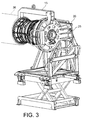
- the aircraft engine module 1 which appears in this embodiment of the invention is called "core" or high pressure body. It is a major intermediate module comprising the compressor and the high pressure turbine, and the combustion chamber. He climbed, according to Figures 1 to 3 , on a carriage 2 comprising a frame 3, rollers 4 mounted on the frame 3 and a frame 5 rising from the frame 3 and carrying the module 1.
- the carriage 2 is, however, raised from the ground and carried by an elevating device 6 comprising a frame 7, and especially arranged in the frame 7, an upper table 8 on which the frame 3 of the carriage 2 is placed, and a mechanism 9 to bar 10 hinged by the middle, disposed between the table 8 and the ground, and which raises that when the hinge angle of the bars 10 is modified by a jack 11.
- a tool 12 taking the appearance of a lid attached to the back of a lid 1 it is originally a "strongback", known in itself and mainly comprising a mount 13 in plate covering the rear of the module 1, to which it is bolted or otherwise fixed by devices not shown, and which allows both to stiffen and protect the module 1, and means, not shown here since already known, carried by the frame 13, to prohibit the translation and rotation movements between the rotor and the stator of the module 1.
- the tool 12 is improved with respect to the known strongbacks: it comprises a protrusion 14 greater than which is fixed a lifting arm 15, the other extr Mite 16 is fixed to the front of the module 1, and which carries in the center a snap ring 18.
- the attachments of the lifting arm are made by inserting a detachable pin 37 through the projection 14 and by a bolting to a flange 17 at the front of module 1.
- complementary attachment means 19 between the tooling 12 and the carriage 2 which comprise a projection 20 standing on the side of the tooling 12, a shoe 21 at the end of the projection 20 and square shape, a groove 22, limited by overhanging edges 23, established in a support 26 at the top of the frame 5, an abutment 24 at the bottom of the groove 22, and a screw 25 between the shoe 21 and the support 26 of the groove 22.
- the support 26 is provided with a pivot 27 of horizontal axis, mounted in the frame 5 and driven by a motor 28, allowing the frame 5 to rotate around this axis.
- the handling handling of module 1 using the device described below is now described.
- the figure 4 shows the module 1 as it appears at the beginning, enclosed in a box 29, with its vertical axis of rotation and the rear of the module 1 directed at the top.
- the first step is to remove a cover 30 of the box 29 and an armature 31 of immobilization of the module 1.
- the module 1 still resting on the bottom 32 of the box 30 but cleared, receives the tooling 12 which is fixed thereto, then the tooling 12 is suspended from a hoist 33 which is hooked to the projection 20 and to a handle 34 (shown in FIG. figure 2 ) projecting from the opposite side of the tooling 12.
- the condition of the figure 5 is obtained.
- the hoist 33 is lifted by driving the tooling 12 and the module 1, a protective cover tooling can then be placed also at the front of the module 1 (the opposite of the tooling 12) and the module 1 is 2.
- Tooling at the front (not shown) is a known "strongback" tool, but it can be lighter and installed by hand, thanks to the handling safety provided by the machine. invention, which subjects module 1 to less effort.
- the installation on the carriage 2 takes place, in the position of the figure 1 , by introducing the shoe 21 into the groove 22, whose orientation is then vertical, leaving down the module 1 until the pad reaches the stop 24, then fixing the screw 25.
- the next step is a rotation of the pivot 27, whose axis crosses that of the module 1, so as to obtain the state represented at the figure 3 by tilting the module 1, its axis then being horizontal and the front of the module 1 protruding from one side of the carriage 2.
- the lifting arm 15 is installed at the top of the assembly, the projection 14 to which it is mounted then being directed upwards.
- the carriage 2 is then moved until it reaches above the table 8 of the elevating device 6, then in a low position and housed in the frame 7; pivotally retractable stops 35 disposed at the front and rear of the frame 3 are then lowered.
- a control of the cylinder 11 produces the rise of the table 8 and the lifting of the carriage 2 and the module 1.
- the hoist 33 can then take the module 1 by the arm to the lift arm 15, lift it from the carriage 2 when the assembly means 19 have been disjointed, then move the module 1 to dock another module 36 of the engine, against which it must be mounted.
- the ring 18 is placed above the center of gravity of the module 1, no tilting is more to be feared.
Landscapes
- Engineering & Computer Science (AREA)
- Structural Engineering (AREA)
- Transportation (AREA)
- Geology (AREA)
- Mechanical Engineering (AREA)
- Life Sciences & Earth Sciences (AREA)
- Civil Engineering (AREA)
- Aviation & Aerospace Engineering (AREA)
- Manufacturing & Machinery (AREA)
- Automatic Assembly (AREA)
- Testing Of Engines (AREA)
- Handcart (AREA)
- Packaging Of Machine Parts And Wound Products (AREA)
Description
L'invention présente a trait à un ensemble de manutention d'un moteur d'aéronef.The present invention relates to a handling assembly of an aircraft engine.
Les moteurs d'aéronefs sont fabriqués d'abord en modules séparés, qui sont ensuite assemblés entre eux. Les modules fabriqués sont transportés au lieu de l'assemblage, puis sortis de leurs emballages et déplacés avec précision jusqu'à leur position d'accostage au module voisin. Les déplacements sont assurés essentiellement par manutention, même si on dispose d'engins tels que les palans pour soulever les modules et de chariots pour les déplacer.Aircraft engines are first manufactured in separate modules, which are then assembled together. The modules manufactured are transported to the assembly site, then removed from their packages and accurately moved to their docking position at the neighboring module. The movements are mainly handled by handling, even if we have gear such as hoists to lift the modules and trolleys to move them.
Cette manutention est longue et difficile puisque les modules de moteurs d'aéronefs sont des pièces volumineuses et lourdes tout en étant fragiles. Une difficulté particulière provient de ce qu'ils sont en général assemblés avec leur axe de rotation horizontal alors qu'ils sont souvent placés avec l'axe de rotation vertical pendant le transport en caisse, afin qu'ils reposent sur une surface d'extrémité plane et que la stabilité au transport soit améliorée: ils doivent donc être renversés quand ils ont été sortis de la caisse, normalement avant d'être placés sur le chariot, mais cette opération est délicate et demande donc beaucoup de précautions. La dépose du module sur un chariot est elle aussi délicate, et il faut ajouter au module des supports spéciaux, appelés «oreilles», pour lui permettre d'y reposer de façon stable et avec une superficie suffisante, ce qui serait impossible autrement à cause de sa forme de révolution en général conique et irrégulière. On doit ajouter qu'il est encore nécessaire d'employer des outillages appelés « strongback », qu'on assemble aux extrémités du module, afin de le renforcer tout en arrêtant les mouvements entre le rotor et le stator avant qu'il ne soit monté aux autres modules.This handling is long and difficult since aircraft engine modules are bulky and heavy parts while being fragile. A particular difficulty is that they are generally assembled with their horizontal axis of rotation while they are often placed with the vertical axis of rotation during shipping, so that they rest on an end surface flat and that the stability to transport is improved: they must be reversed when they have been removed from the box, normally before being placed on the carriage, but this operation is delicate and therefore requires a lot of precautions. The removal of the module on a carriage is also delicate, and must be added to the module special media, called "ears", to allow it to rest stably and with a sufficient area, which would be impossible otherwise because of its generally conical and irregular form of revolution. We must add that it is still necessary to use tools called "strongback", which is assembled at the ends of the module, to strengthen it while stopping the movement between the rotor and the stator before it is mounted to other modules.
L'invention est relative à un ensemble de manutention d'un module de moteur d'aéronef qui évite les inconvénients mentionnés et permet de préparer le montage du module à un module voisin dans de meilleures conditions de travail, plus rapidement et avec des interventions manuelles beaucoup réduites et nécessitant moins de précaution.The invention relates to a handling assembly of an aircraft engine module which avoids the disadvantages mentioned and makes it possible to prepare the mounting of the module to a neighboring module in better working conditions, more quickly and with manual interventions. much reduced and requiring less precaution.
Sous une forme générale, l'invention concerne un ensemble de manutention d'un module de moteur d'aéronef, comprenant un chariot mobile et un outillage placé à une extrémité du module, l'outillage comprenant une monture et des dispositifs de fixation au module, et caractérisé en ce que le chariot comprend une armature supérieure établie sur un châssis de support du module et pivotant autour d'un axe horizontal, l'armature supérieure et l'outillage comprenant des dispositifs complémentaires de fixation du module au chariot dans une position où un axe du module croise l'axe horizontal.In a general form, the invention relates to a handling assembly of an aircraft engine module, comprising a mobile carriage and a tool placed at one end of the module, the tooling comprising a mounting and fixing devices to the module. , and characterized in that the carriage comprises an upper armature established on a support frame of the module and pivotable about a horizontal axis, the upper armature and the tooling comprising complementary devices for fixing the module to the carriage in a position where an axis of the module crosses the axis horizontal.
Le module de moteur est ainsi fixé au chariot par l'intermédiaire de l'outillage, qui est avantageusement un « strongback » adapté pour l'invention : on évite ainsi de déposer le module sur le chariot de façon directe ou par l'intermédiaire d'une «oreille», ce qui réduit les risques d'endommagement par choc ou par pression de contact excessive. Et le basculement du module, nécessaire pour passer de la configuration de transport à axe de rotation vertical à la configuration de montage à axe de rotation horizontal, est accompli de façon simple par le chariot, sans effort ni précaution particulière pour éviter des collisions ou ajuster l'orientation atteinte par le module.The motor module is thus fixed to the trolley by means of the tooling, which is advantageously a "strongback" adapted to the invention: it thus avoids depositing the module on the trolley directly or via an "ear", which reduces the risk of damage by shock or excessive contact pressure. And the tilting of the module, necessary to move from the transport configuration to vertical axis of rotation to the configuration of horizontal axis of rotation, is accomplished in a simple way by the truck, without any special effort or precaution to avoid collisions or to adjust the orientation reached by the module.
Un élément important de l'ensemble est relatif à l'élévation du châssis, afin d'ajuster la hauteur du module au moment de l'assemblage. On y parvient au moyen d'un dispositif qui peut être indépendant du chariot et qui comprend alors une table fixe au lieu où l'assemblage pourrait s'effectuer. Le chariot est apporté au-dessus de la table, qui le soulève à la hauteur voulue, le module restant solidement fixé au chariot.An important element of the assembly is relative to the elevation of the frame, in order to adjust the height of the module at the time of assembly. This is achieved by means of a device which can be independent of the carriage and which then comprises a fixed table at the place where the assembly could take place. The carriage is brought over the table, which raises it to the desired height, the module remaining firmly attached to the carriage.
L'assemblage peut être accompli en libérant le module du chariot et en le soulevant par un palan. L'ensemble de manutention peut alors être complété par un bras de levage s'étendant d'une extrémité à l'autre du module, en étant par exemple fixé au module par une extrémité et à l'outillage par l'autre extrémité, et muni de moyens d'accrochage qui permettent de le soulever au centre de gravité du module, qui ne risque plus donc de basculer.Assembly can be accomplished by releasing the module from the cart and lifting it with a hoist. The handling assembly can then be completed by a lifting arm extending from one end to the other of the module, being for example fixed to the module at one end and to the tooling at the other end, and equipped with hooking means that can lift it to the center of gravity of the module, which is no longer likely to switch.
L'invention sera maintenant décrite plus en détail au moyen des figures, parmi lesquelles :
- la
figure 1 représente le module monté sur le chariot, - les
figures 2 et3 représentent le module monté sur le chariot après le basculement, - la
figure 4 illustre le module à son arrivée au lieu de l'assemblage, avant d'employer le chariot, - et la
figure 5 illustre le module juste avant d'être installé sur le chariot.
- the
figure 1 represents the module mounted on the carriage, - the
figures 2 and3 represent the module mounted on the truck after tilting, - the
figure 4 illustrates the module upon arrival instead of assembly, before using the carriage, - and the
figure 5 illustrates the module just before being installed on the cart.
Le module 1 de moteur d'aéronef qui apparaît dans ce mode de réalisation de l'invention est appelé « core », ou corps à haute pression. Il s'agit d'un module majeur intermédiaire comprenant le compresseur et la turbine à haute pression, et la chambre de combustion. Il est monté, d'après les
D'autres détails du dispositif sont des moyens complémentaires de fixation 19 entre l'outillage 12 et le chariot 2, qui comprennent une saillie 20 se dressant sur le côté de l'outillage 12, un patin 21 au bout de la saillie 20 et de forme carrée, une rainure 22, limitée par des rebords en surplomb 23, établie dans un support 26 au sommet de l'armature 5, une butée 24 au fond de la rainure 22, et une vis 25 entre le patin 21 et le support 26 de la rainure 22. Le support 26 est muni d'un pivot 27 d'axe horizontal, monté dans l'armature 5 et entraîné par un moteur 28, permettant à l'armature 5 de tourner autour de cet axe.Other details of the device are complementary attachment means 19 between the
Le traitement de manutention du module 1 en utilisant le dispositif décrit ci-dessous est maintenant décrit. La
Certaines de ces opérations peuvent être accomplies dans un ordre différent: notamment la rotation du module 1, l'enlèvement du palan 33 et l'élévation de la table 8. Il faut noter que si on a représenté un dispositif d'élévation 6 fixe et proche du lieu de montage du module 1, cela n'est pas nécessaire et le dispositif d'élévation 6 aurait pu être intégré au chariot 2.Some of these operations can be performed in a different order: in particular the rotation of the
Claims (5)
- An aircraft engine module handling assembly (1), including a moving carriage (2) and tooling (12) positioned at an end of the module (1), where the tooling includes a mount (13) and devices for attachment to the module, characterised in that the carriage includes an upper reinforcement structure (5) set up on a module support frame (3), and pivoting around a horizontal axis (27), where the upper reinforcement structure (5) and the tooling (12) include additional devices (19) for securing the module to the carriage in a position in which an axis of rotation of the module intersects the horizontal axis.
- An aircraft engine module handling assembly according to claim 1, characterised in that the additional attachment devices include a groove (22) limited by overhanging edges (23), where a skid (21) sliding in the groove (22) and attached to a projection (20) of the tooling (12) extends out of the groove, with a stop (24) of the skid in the groove and a means (25) of immobilising the skid at the stop in the groove.
- An aircraft engine module handling assembly according to either of the claims 1 or 2, characterised in that it includes a device (6) for raising the frame (3).
- An aircraft engine module handling assembly according to claim 3, characterised in that the device (6) for raising the frame includes a table (8) independent of the carriage, and on which the carriage can roll, and where there are immobilising stops (35) between the table (8) and the carriage (2).
- An aircraft engine module handling assembly according to any of the claims 1 to 4, characterised in that it includes a lifting arm (15) able to be assembled at one end with the tooling (12) and, at an opposite end (16), at a location (17) of the module which is opposite the tooling.
Applications Claiming Priority (2)
| Application Number | Priority Date | Filing Date | Title |
|---|---|---|---|
| FR0958240A FR2952922B1 (en) | 2009-11-20 | 2009-11-20 | HANDLING ASSEMBLY FOR AN AIRCRAFT ENGINE MODULE |
| PCT/EP2010/067858 WO2011061307A1 (en) | 2009-11-20 | 2010-11-19 | Assembly for handling an aircraft engine |
Publications (2)
| Publication Number | Publication Date |
|---|---|
| EP2501642A1 EP2501642A1 (en) | 2012-09-26 |
| EP2501642B1 true EP2501642B1 (en) | 2013-10-16 |
Family
ID=42238793
Family Applications (1)
| Application Number | Title | Priority Date | Filing Date |
|---|---|---|---|
| EP10778670.9A Active EP2501642B1 (en) | 2009-11-20 | 2010-11-19 | Handling system for an aircraft engine module |
Country Status (9)
| Country | Link |
|---|---|
| US (1) | US9309008B2 (en) |
| EP (1) | EP2501642B1 (en) |
| JP (1) | JP5701310B2 (en) |
| CN (1) | CN102666360B (en) |
| BR (1) | BR112012011998B1 (en) |
| CA (1) | CA2781226C (en) |
| FR (1) | FR2952922B1 (en) |
| RU (1) | RU2544425C2 (en) |
| WO (1) | WO2011061307A1 (en) |
Families Citing this family (30)
| Publication number | Priority date | Publication date | Assignee | Title |
|---|---|---|---|---|
| FR2969021B1 (en) | 2010-12-16 | 2014-04-11 | Commissariat Energie Atomique | STRUCTURE CUTTING DEVICE COMPRISING WIRED NANO-OBJECTS AND ASSOCIATED METHOD |
| US9228451B2 (en) * | 2011-05-03 | 2016-01-05 | Pratt & Whitney Canada Corp. | Gas turbine engine module adapter to a carrier |
| FR2980982B1 (en) | 2011-10-07 | 2014-10-24 | Commissariat Energie Atomique | DEVICE COMPRISING A COMPOSITE MATERIAL HAVING ELECTRIC FIELD SUBSTRATE NANOTUBES AND USES THEREOF |
| FR2990190B1 (en) * | 2012-05-02 | 2015-06-19 | Snecma | TOOL FOR HANDLING AN AIRCRAFT ENGINE MODULE |
| US9925629B2 (en) * | 2013-05-29 | 2018-03-27 | The Boeing Company | Modular and reconfigurable support system |
| FR3008070B1 (en) * | 2013-07-08 | 2020-11-06 | Astrium Sas | REUSABLE LAUNCH VEHICLE THROTTLE BLOCK |
| GB2509230A (en) * | 2013-11-19 | 2014-06-25 | Rolls Royce Plc | Gas turbine engine stand with slide rail and lock mechanism |
| CN103639973B (en) * | 2013-11-28 | 2015-11-18 | 江西洪都航空工业集团有限责任公司 | A kind of aircraft engine erection unit |
| US9738391B2 (en) | 2014-03-10 | 2017-08-22 | United Technologies Corporation | Engine installation system |
| US10525524B2 (en) | 2014-07-09 | 2020-01-07 | The Boeing Company | Dual-interface coupler |
| JP6533043B2 (en) | 2014-08-25 | 2019-06-19 | 三菱航空機株式会社 | Aircraft engine installation method |
| US10196199B2 (en) | 2016-06-01 | 2019-02-05 | General Electric Company | Convertible support structures for shipping large machinery |
| US10279829B2 (en) * | 2016-07-15 | 2019-05-07 | Charles William Walkner | Ergonomic carts for metal forming operations |
| US10131389B1 (en) * | 2017-04-27 | 2018-11-20 | Toyota Motor Engineering & Manufacturing North America, Inc. | Automated guided cart independent securing device |
| CN107089616A (en) * | 2017-05-05 | 2017-08-25 | 昆明理工大学 | A kind of hoistable platform |
| CN107671582B (en) * | 2017-08-29 | 2024-02-06 | 浙江昊能光电股份有限公司 | Main shaft replacing device for efficient slicing machine |
| PL3450704T3 (en) * | 2017-09-01 | 2021-02-22 | General Electric Technology Gmbh | Turbine bearing maintenance apparatus and method |
| EP3460272B1 (en) * | 2017-09-20 | 2020-04-01 | Siemens Gamesa Renewable Energy A/S | Method for changing a bearing component and tool device for changing a bearing component |
| CN107697861B (en) * | 2017-10-16 | 2019-06-07 | 国网新疆电力公司检修公司 | Intelligent component cabinet of substation air-conditioning replaces auxiliary device |
| CN108100959B (en) * | 2017-11-21 | 2019-10-25 | 北京特种机械研究所 | A kind of abnormity cylinder mounting plate |
| CN108502206B (en) * | 2018-03-16 | 2020-05-08 | 中国航天空气动力技术研究院 | Double-deck unmanned aerial vehicle fuselage transportation bracket of multipurpose |
| CN109368509B (en) * | 2018-11-18 | 2020-03-31 | 大连四达高技术发展有限公司 | Intelligent assembly system for aircraft engine |
| FR3090588B1 (en) * | 2018-12-21 | 2021-01-22 | Safran Aircraft Engines | TOOLS FOR PLACING A PROPELLENT ASSEMBLY FROM A HORIZONTAL POSITION TO A VERTICAL POSITION |
| DE102019201797A1 (en) * | 2019-02-12 | 2020-08-13 | MTU Aero Engines AG | Turning stand |
| US11248497B2 (en) * | 2019-04-30 | 2022-02-15 | Pratt & Whitney Canada Corp. | Gas turbine engine yoke and build support |
| CN110640443B (en) * | 2019-09-03 | 2021-05-04 | 黄鹄科学技术有限公司 | Vehicle-mounted equipment installs frock |
| CN112145285B (en) * | 2020-08-14 | 2021-09-24 | 武汉司南翼航航空工程技术有限责任公司 | Low-oil-consumption long-endurance aircraft engine |
| CN116096637A (en) | 2020-08-19 | 2023-05-09 | 赛峰航空助推器股份有限公司 | Cart for assembling and transporting an aircraft engine to a test room |
| CN112977872B (en) * | 2021-03-29 | 2022-06-10 | 浙江大学 | Device and method for installing air inlet channel |
| US11247787B1 (en) * | 2021-07-20 | 2022-02-15 | NextGen Aero Support, LLC | Aircraft engine storage frame and system |
Family Cites Families (34)
| Publication number | Priority date | Publication date | Assignee | Title |
|---|---|---|---|---|
| US1481503A (en) * | 1920-09-24 | 1924-01-22 | Carswell Joseph Sinclair | Repair stand for motors |
| US1600835A (en) * | 1921-10-29 | 1926-09-21 | Robert E Manley | Engine stand |
| US1812585A (en) * | 1928-09-21 | 1931-06-30 | Atlas Press Company | Engine stand |
| FR868161A (en) | 1938-09-19 | 1941-12-23 | Messerschmitt Boelkow Blohm | Trolley for auxiliary devices of different external shape and dimensions, especially for the construction of airplanes |
| US2712874A (en) * | 1950-05-12 | 1955-07-12 | Lockheed Aircraft Corp | Portable aircraft lifting cradle |
| US2825477A (en) | 1953-09-04 | 1958-03-04 | Henry M Ross | Engine work stand and method of using the same |
| US2763053A (en) * | 1955-06-09 | 1956-09-18 | Wisconsin Hydraulics Inc | Universal work positioners |
| US3318466A (en) * | 1965-06-16 | 1967-05-09 | Lockheed Aircraft Corp | Tool for removing and replacing component structures of aircraft |
| US3355162A (en) * | 1966-06-07 | 1967-11-28 | Robert M Kerr | Repair stand |
| DE2719850C3 (en) | 1977-05-04 | 1981-06-25 | MTU Motoren- und Turbinen-Union München GmbH, 8000 München | Device for the maintenance of gas turbine engines, in particular gas turbine jet engines |
| FR2478575A1 (en) * | 1980-03-19 | 1981-09-25 | Snecma | DEVICE FOR PLACING A REACTOR IN AN AIRCRAFT CELL |
| DE3427042A1 (en) * | 1984-07-21 | 1985-02-21 | Scheele Ing.-Büro GmbH, 2875 Ganderkesee | Universal aircraft engine changing device |
| US4691904A (en) | 1985-08-08 | 1987-09-08 | Robert J. Williams | Automatic or standard transmission handling device |
| US4682750A (en) * | 1986-09-26 | 1987-07-28 | Eidos Corporation | Low profile extensible support platform |
| JPH01237230A (en) * | 1988-03-18 | 1989-09-21 | Kawasaki Heavy Ind Ltd | Engine holding/transporting device |
| RU2076831C1 (en) * | 1990-04-23 | 1997-04-10 | Акционерное общество открытого типа "Нижегородский авиастроительный завод "Сокол" | Device for transportation, hoisting and suspending of cargo on flying vehicles |
| US5816367A (en) * | 1995-11-30 | 1998-10-06 | Stanley Aviation Corporation | Jet aircraft engine transport apparatus |
| US5863034A (en) * | 1996-10-24 | 1999-01-26 | Vauter; Andrew F. | Work piece stand |
| DE20023688U1 (en) | 2000-06-19 | 2005-08-11 | Berger, Erwin | Trolley for transporting door between work stations and supporting it during processing has posts at each end which carry holders consisting of bars which are thinner than the door and are positioned symmetrically at each end of it |
| US6490906B1 (en) * | 2001-03-02 | 2002-12-10 | Rick H. Bailey | Vehicle body repair tool |
| US6619640B1 (en) * | 2001-08-28 | 2003-09-16 | Gregory Ploski | Support and rotating apparatus for heavy vehicle components mounted on a carriage |
| RU2209155C1 (en) * | 2001-12-05 | 2003-07-27 | Открытое акционерное общество "Ракетно-космическая корпорация "Энергия" им. С.П.Королева" | Method of assembly of nose unit on adapter of launch vehicle (variants) and device for realization of this method |
| CN2554091Y (en) * | 2002-06-28 | 2003-06-04 | 焦宇 | Maintaining working platform for aircraft seat |
| FR2860175B1 (en) | 2003-09-26 | 2006-03-10 | Plastic Omnium Cie | CHASSIS OF MOTOR VEHICLE MOUNTING BUILDING STATION AND BUILDING MOUNT OF MOTOR VEHICLES |
| WO2005124789A1 (en) * | 2004-06-15 | 2005-12-29 | Thk Co., Ltd. | Xy guide table |
| DE202004018795U1 (en) * | 2004-12-03 | 2006-04-13 | Kuka Schweissanlagen Gmbh | Workpiece |
| US20090020934A1 (en) * | 2005-09-29 | 2009-01-22 | W.P.R.W.M.D.M., L.L.C. | Equipment handling apparatus and system |
| GB0613929D0 (en) * | 2006-07-13 | 2006-08-23 | Rolls Royce Plc | An engine core stand arrangement and method of removal and transportation of an engine core |
| US7963542B2 (en) * | 2008-08-29 | 2011-06-21 | Solar Turbines Incorporated | Modular cart for a gas turbine engine |
| US8262050B2 (en) * | 2008-12-24 | 2012-09-11 | General Electric Company | Method and apparatus for mounting and dismounting an aircraft engine |
| US8621873B2 (en) * | 2008-12-29 | 2014-01-07 | Solar Turbines Inc. | Mobile platform system for a gas turbine engine |
| FR2948636B1 (en) * | 2009-07-31 | 2012-01-13 | Airbus Operations Sas | AIRCRAFT ENGINE ASSEMBLY INCLUDING A STRUCTURAL ENVELOPE FOR THE INTERNAL RADIAL DELIMITATION OF THE SECONDARY FLOW |
| FR2952921B1 (en) * | 2009-11-20 | 2012-05-25 | Snecma | TRANSPORT TROLLEY FOR AN AIRCRAFT ENGINE MODULE |
| FR2969021B1 (en) | 2010-12-16 | 2014-04-11 | Commissariat Energie Atomique | STRUCTURE CUTTING DEVICE COMPRISING WIRED NANO-OBJECTS AND ASSOCIATED METHOD |
-
2009
- 2009-11-20 FR FR0958240A patent/FR2952922B1/en not_active Expired - Fee Related
-
2010
- 2010-11-19 US US13/509,304 patent/US9309008B2/en active Active
- 2010-11-19 RU RU2012124417/11A patent/RU2544425C2/en active
- 2010-11-19 CN CN201080052516.0A patent/CN102666360B/en active Active
- 2010-11-19 BR BR112012011998-2A patent/BR112012011998B1/en active IP Right Grant
- 2010-11-19 EP EP10778670.9A patent/EP2501642B1/en active Active
- 2010-11-19 JP JP2012539344A patent/JP5701310B2/en active Active
- 2010-11-19 WO PCT/EP2010/067858 patent/WO2011061307A1/en active Application Filing
- 2010-11-19 CA CA2781226A patent/CA2781226C/en active Active
Also Published As
| Publication number | Publication date |
|---|---|
| RU2544425C2 (en) | 2015-03-20 |
| US9309008B2 (en) | 2016-04-12 |
| WO2011061307A1 (en) | 2011-05-26 |
| EP2501642A1 (en) | 2012-09-26 |
| JP5701310B2 (en) | 2015-04-15 |
| BR112012011998A2 (en) | 2016-05-10 |
| RU2012124417A (en) | 2013-12-27 |
| BR112012011998B1 (en) | 2020-08-11 |
| CA2781226C (en) | 2017-01-10 |
| FR2952922B1 (en) | 2012-05-25 |
| US20120224944A1 (en) | 2012-09-06 |
| JP2013511643A (en) | 2013-04-04 |
| FR2952922A1 (en) | 2011-05-27 |
| CN102666360A (en) | 2012-09-12 |
| CA2781226A1 (en) | 2011-05-26 |
| CN102666360B (en) | 2015-04-01 |
Similar Documents
| Publication | Publication Date | Title |
|---|---|---|
| EP2501642B1 (en) | Handling system for an aircraft engine module | |
| EP0147246B1 (en) | Turbo engine transport stand | |
| EP3278930B1 (en) | Device for installing or removing a motor vehicle window pane | |
| WO2006021715A1 (en) | Lifting assembly | |
| FR2887396A1 (en) | AUTOPORATED TURF MOWER HAVING A FRONT MOWER UNIT | |
| EP3838666B1 (en) | Support for lifting container by upper holes of the container | |
| FR2990190A1 (en) | Tool for handling high pressure module of turbojet of aircraft, has fixing arms connected to vertical branches of support body by pivot joint, so as to allow rotation of high pressure module about horizontal rotation axis between branches | |
| WO2015185811A1 (en) | Assembly for handling an aircraft engine | |
| EP2649004B1 (en) | Tool for handling a sewer cover | |
| FR2822145A1 (en) | Elevator nacelle for working at height has mountings for load-supporting structure with two configurations | |
| EP0330572A1 (en) | Retractable loading/unloading arm, and vehicle fitted therewith | |
| EP4015313B1 (en) | Device for holding and depositing a device in relation to an outer wall of a vehicle and method implementing such a device | |
| FR2814038A1 (en) | LIFT DEVICE FOR A TRACTOR FOR ATTACHING AND DETECTING A MASS WITHOUT MANUAL INTERVENTION | |
| EP3617131A1 (en) | Yoke, system for lifting and setting down comprising such a yoke and method for lifting and setting down of a vehicle | |
| EP2829501B1 (en) | Cantilever mounting device of a carriage on the rear of a carrier vehicle such as a truck | |
| EP3889094B1 (en) | Crane with automated assembly comprising a removable ballasting element for transport on a fifth wheel | |
| FR2867497A1 (en) | Concrete block stripping assistance device for use in building construction, has base mounted on wheels for carrying support mast, and mast head to be stopped against nearby stripping plate or concrete slab during lifting of telescopic mast | |
| EP2602210B1 (en) | Container for motor vehicle parts | |
| BE1011735A3 (en) | Portable device for fitting and removing a wheel | |
| EP2096077B1 (en) | Self-propelled personnel lift device | |
| EP3383787B1 (en) | Maintenance method and system for solar receiver | |
| EP2821280B1 (en) | Removable container for vehicle | |
| EP2602211B1 (en) | Device for supporting a motor vehicle part enabling said part to tilt | |
| FR2524404A1 (en) | Elevating platform esp. for industrial vehicles - comprises articulated arm which can move vertically to or from ground | |
| EP2727877A1 (en) | Hydraulic lawnmower lifting device with adjustable width |
Legal Events
| Date | Code | Title | Description |
|---|---|---|---|
| PUAI | Public reference made under article 153(3) epc to a published international application that has entered the european phase |
Free format text: ORIGINAL CODE: 0009012 |
|
| 17P | Request for examination filed |
Effective date: 20120611 |
|
| AK | Designated contracting states |
Kind code of ref document: A1 Designated state(s): AL AT BE BG CH CY CZ DE DK EE ES FI FR GB GR HR HU IE IS IT LI LT LU LV MC MK MT NL NO PL PT RO RS SE SI SK SM TR |
|
| DAX | Request for extension of the european patent (deleted) | ||
| REG | Reference to a national code |
Ref country code: DE Ref legal event code: R079 Ref document number: 602010011039 Country of ref document: DE Free format text: PREVIOUS MAIN CLASS: B66F0009120000 Ipc: B64F0005000000 |
|
| RIC1 | Information provided on ipc code assigned before grant |
Ipc: B66F 7/06 20060101ALI20130314BHEP Ipc: B25H 1/00 20060101ALI20130314BHEP Ipc: B66C 23/48 20060101ALI20130314BHEP Ipc: B64F 5/00 20060101AFI20130314BHEP Ipc: B66F 9/06 20060101ALI20130314BHEP |
|
| GRAP | Despatch of communication of intention to grant a patent |
Free format text: ORIGINAL CODE: EPIDOSNIGR1 |
|
| INTG | Intention to grant announced |
Effective date: 20130531 |
|
| GRAS | Grant fee paid |
Free format text: ORIGINAL CODE: EPIDOSNIGR3 |
|
| GRAA | (expected) grant |
Free format text: ORIGINAL CODE: 0009210 |
|
| AK | Designated contracting states |
Kind code of ref document: B1 Designated state(s): AL AT BE BG CH CY CZ DE DK EE ES FI FR GB GR HR HU IE IS IT LI LT LU LV MC MK MT NL NO PL PT RO RS SE SI SK SM TR |
|
| REG | Reference to a national code |
Ref country code: GB Ref legal event code: FG4D Free format text: NOT ENGLISH |
|
| REG | Reference to a national code |
Ref country code: CH Ref legal event code: EP |
|
| REG | Reference to a national code |
Ref country code: IE Ref legal event code: FG4D Free format text: LANGUAGE OF EP DOCUMENT: FRENCH |
|
| REG | Reference to a national code |
Ref country code: AT Ref legal event code: REF Ref document number: 636366 Country of ref document: AT Kind code of ref document: T Effective date: 20131115 |
|
| REG | Reference to a national code |
Ref country code: DE Ref legal event code: R096 Ref document number: 602010011039 Country of ref document: DE Effective date: 20131212 |
|
| REG | Reference to a national code |
Ref country code: SE Ref legal event code: TRGR |
|
| REG | Reference to a national code |
Ref country code: NL Ref legal event code: VDEP Effective date: 20131016 |
|
| REG | Reference to a national code |
Ref country code: AT Ref legal event code: MK05 Ref document number: 636366 Country of ref document: AT Kind code of ref document: T Effective date: 20131016 |
|
| REG | Reference to a national code |
Ref country code: LT Ref legal event code: MG4D |
|
| PG25 | Lapsed in a contracting state [announced via postgrant information from national office to epo] |
Ref country code: LT Free format text: LAPSE BECAUSE OF FAILURE TO SUBMIT A TRANSLATION OF THE DESCRIPTION OR TO PAY THE FEE WITHIN THE PRESCRIBED TIME-LIMIT Effective date: 20131016 Ref country code: NL Free format text: LAPSE BECAUSE OF FAILURE TO SUBMIT A TRANSLATION OF THE DESCRIPTION OR TO PAY THE FEE WITHIN THE PRESCRIBED TIME-LIMIT Effective date: 20131016 Ref country code: IS Free format text: LAPSE BECAUSE OF FAILURE TO SUBMIT A TRANSLATION OF THE DESCRIPTION OR TO PAY THE FEE WITHIN THE PRESCRIBED TIME-LIMIT Effective date: 20140216 Ref country code: FI Free format text: LAPSE BECAUSE OF FAILURE TO SUBMIT A TRANSLATION OF THE DESCRIPTION OR TO PAY THE FEE WITHIN THE PRESCRIBED TIME-LIMIT Effective date: 20131016 Ref country code: HR Free format text: LAPSE BECAUSE OF FAILURE TO SUBMIT A TRANSLATION OF THE DESCRIPTION OR TO PAY THE FEE WITHIN THE PRESCRIBED TIME-LIMIT Effective date: 20131016 Ref country code: NO Free format text: LAPSE BECAUSE OF FAILURE TO SUBMIT A TRANSLATION OF THE DESCRIPTION OR TO PAY THE FEE WITHIN THE PRESCRIBED TIME-LIMIT Effective date: 20140116 |
|
| PG25 | Lapsed in a contracting state [announced via postgrant information from national office to epo] |
Ref country code: CY Free format text: LAPSE BECAUSE OF FAILURE TO SUBMIT A TRANSLATION OF THE DESCRIPTION OR TO PAY THE FEE WITHIN THE PRESCRIBED TIME-LIMIT Effective date: 20131016 Ref country code: LV Free format text: LAPSE BECAUSE OF FAILURE TO SUBMIT A TRANSLATION OF THE DESCRIPTION OR TO PAY THE FEE WITHIN THE PRESCRIBED TIME-LIMIT Effective date: 20131016 Ref country code: AT Free format text: LAPSE BECAUSE OF FAILURE TO SUBMIT A TRANSLATION OF THE DESCRIPTION OR TO PAY THE FEE WITHIN THE PRESCRIBED TIME-LIMIT Effective date: 20131016 Ref country code: ES Free format text: LAPSE BECAUSE OF FAILURE TO SUBMIT A TRANSLATION OF THE DESCRIPTION OR TO PAY THE FEE WITHIN THE PRESCRIBED TIME-LIMIT Effective date: 20131016 Ref country code: RS Free format text: LAPSE BECAUSE OF FAILURE TO SUBMIT A TRANSLATION OF THE DESCRIPTION OR TO PAY THE FEE WITHIN THE PRESCRIBED TIME-LIMIT Effective date: 20131016 |
|
| BERE | Be: lapsed |
Owner name: SNECMA Effective date: 20131130 |
|
| PG25 | Lapsed in a contracting state [announced via postgrant information from national office to epo] |
Ref country code: PT Free format text: LAPSE BECAUSE OF FAILURE TO SUBMIT A TRANSLATION OF THE DESCRIPTION OR TO PAY THE FEE WITHIN THE PRESCRIBED TIME-LIMIT Effective date: 20140217 |
|
| REG | Reference to a national code |
Ref country code: DE Ref legal event code: R097 Ref document number: 602010011039 Country of ref document: DE |
|
| PG25 | Lapsed in a contracting state [announced via postgrant information from national office to epo] |
Ref country code: MC Free format text: LAPSE BECAUSE OF FAILURE TO SUBMIT A TRANSLATION OF THE DESCRIPTION OR TO PAY THE FEE WITHIN THE PRESCRIBED TIME-LIMIT Effective date: 20131016 Ref country code: EE Free format text: LAPSE BECAUSE OF FAILURE TO SUBMIT A TRANSLATION OF THE DESCRIPTION OR TO PAY THE FEE WITHIN THE PRESCRIBED TIME-LIMIT Effective date: 20131016 |
|
| PLBE | No opposition filed within time limit |
Free format text: ORIGINAL CODE: 0009261 |
|
| STAA | Information on the status of an ep patent application or granted ep patent |
Free format text: STATUS: NO OPPOSITION FILED WITHIN TIME LIMIT |
|
| REG | Reference to a national code |
Ref country code: IE Ref legal event code: MM4A |
|
| PG25 | Lapsed in a contracting state [announced via postgrant information from national office to epo] |
Ref country code: RO Free format text: LAPSE BECAUSE OF FAILURE TO SUBMIT A TRANSLATION OF THE DESCRIPTION OR TO PAY THE FEE WITHIN THE PRESCRIBED TIME-LIMIT Effective date: 20131016 Ref country code: PL Free format text: LAPSE BECAUSE OF FAILURE TO SUBMIT A TRANSLATION OF THE DESCRIPTION OR TO PAY THE FEE WITHIN THE PRESCRIBED TIME-LIMIT Effective date: 20131016 Ref country code: SK Free format text: LAPSE BECAUSE OF FAILURE TO SUBMIT A TRANSLATION OF THE DESCRIPTION OR TO PAY THE FEE WITHIN THE PRESCRIBED TIME-LIMIT Effective date: 20131016 Ref country code: CZ Free format text: LAPSE BECAUSE OF FAILURE TO SUBMIT A TRANSLATION OF THE DESCRIPTION OR TO PAY THE FEE WITHIN THE PRESCRIBED TIME-LIMIT Effective date: 20131016 |
|
| 26N | No opposition filed |
Effective date: 20140717 |
|
| PG25 | Lapsed in a contracting state [announced via postgrant information from national office to epo] |
Ref country code: BE Free format text: LAPSE BECAUSE OF NON-PAYMENT OF DUE FEES Effective date: 20131130 Ref country code: DK Free format text: LAPSE BECAUSE OF FAILURE TO SUBMIT A TRANSLATION OF THE DESCRIPTION OR TO PAY THE FEE WITHIN THE PRESCRIBED TIME-LIMIT Effective date: 20131016 |
|
| REG | Reference to a national code |
Ref country code: DE Ref legal event code: R097 Ref document number: 602010011039 Country of ref document: DE Effective date: 20140717 |
|
| PG25 | Lapsed in a contracting state [announced via postgrant information from national office to epo] |
Ref country code: IE Free format text: LAPSE BECAUSE OF NON-PAYMENT OF DUE FEES Effective date: 20131119 |
|
| PG25 | Lapsed in a contracting state [announced via postgrant information from national office to epo] |
Ref country code: SI Free format text: LAPSE BECAUSE OF FAILURE TO SUBMIT A TRANSLATION OF THE DESCRIPTION OR TO PAY THE FEE WITHIN THE PRESCRIBED TIME-LIMIT Effective date: 20131016 |
|
| PG25 | Lapsed in a contracting state [announced via postgrant information from national office to epo] |
Ref country code: SM Free format text: LAPSE BECAUSE OF FAILURE TO SUBMIT A TRANSLATION OF THE DESCRIPTION OR TO PAY THE FEE WITHIN THE PRESCRIBED TIME-LIMIT Effective date: 20131016 |
|
| REG | Reference to a national code |
Ref country code: CH Ref legal event code: PL |
|
| PG25 | Lapsed in a contracting state [announced via postgrant information from national office to epo] |
Ref country code: LI Free format text: LAPSE BECAUSE OF NON-PAYMENT OF DUE FEES Effective date: 20141130 Ref country code: CH Free format text: LAPSE BECAUSE OF NON-PAYMENT OF DUE FEES Effective date: 20141130 Ref country code: MK Free format text: LAPSE BECAUSE OF FAILURE TO SUBMIT A TRANSLATION OF THE DESCRIPTION OR TO PAY THE FEE WITHIN THE PRESCRIBED TIME-LIMIT Effective date: 20131016 Ref country code: BG Free format text: LAPSE BECAUSE OF FAILURE TO SUBMIT A TRANSLATION OF THE DESCRIPTION OR TO PAY THE FEE WITHIN THE PRESCRIBED TIME-LIMIT Effective date: 20131016 Ref country code: HU Free format text: LAPSE BECAUSE OF FAILURE TO SUBMIT A TRANSLATION OF THE DESCRIPTION OR TO PAY THE FEE WITHIN THE PRESCRIBED TIME-LIMIT; INVALID AB INITIO Effective date: 20101119 Ref country code: LU Free format text: LAPSE BECAUSE OF NON-PAYMENT OF DUE FEES Effective date: 20131119 |
|
| PG25 | Lapsed in a contracting state [announced via postgrant information from national office to epo] |
Ref country code: GR Free format text: LAPSE BECAUSE OF NON-PAYMENT OF DUE FEES Effective date: 20131016 Ref country code: MT Free format text: LAPSE BECAUSE OF FAILURE TO SUBMIT A TRANSLATION OF THE DESCRIPTION OR TO PAY THE FEE WITHIN THE PRESCRIBED TIME-LIMIT Effective date: 20131016 |
|
| REG | Reference to a national code |
Ref country code: FR Ref legal event code: PLFP Year of fee payment: 6 |
|
| PG25 | Lapsed in a contracting state [announced via postgrant information from national office to epo] |
Ref country code: GR Free format text: LAPSE BECAUSE OF FAILURE TO SUBMIT A TRANSLATION OF THE DESCRIPTION OR TO PAY THE FEE WITHIN THE PRESCRIBED TIME-LIMIT Effective date: 20140117 |
|
| PG25 | Lapsed in a contracting state [announced via postgrant information from national office to epo] |
Ref country code: TR Free format text: LAPSE BECAUSE OF FAILURE TO SUBMIT A TRANSLATION OF THE DESCRIPTION OR TO PAY THE FEE WITHIN THE PRESCRIBED TIME-LIMIT Effective date: 20131016 |
|
| REG | Reference to a national code |
Ref country code: FR Ref legal event code: PLFP Year of fee payment: 7 |
|
| REG | Reference to a national code |
Ref country code: FR Ref legal event code: PLFP Year of fee payment: 8 |
|
| REG | Reference to a national code |
Ref country code: FR Ref legal event code: CD Owner name: SAFRAN AIRCRAFT ENGINES, FR Effective date: 20170719 |
|
| REG | Reference to a national code |
Ref country code: FR Ref legal event code: PLFP Year of fee payment: 9 |
|
| PG25 | Lapsed in a contracting state [announced via postgrant information from national office to epo] |
Ref country code: AL Free format text: LAPSE BECAUSE OF FAILURE TO SUBMIT A TRANSLATION OF THE DESCRIPTION OR TO PAY THE FEE WITHIN THE PRESCRIBED TIME-LIMIT Effective date: 20131016 |
|
| PGFP | Annual fee paid to national office [announced via postgrant information from national office to epo] |
Ref country code: GB Payment date: 20231019 Year of fee payment: 14 |
|
| PGFP | Annual fee paid to national office [announced via postgrant information from national office to epo] |
Ref country code: SE Payment date: 20231020 Year of fee payment: 14 Ref country code: IT Payment date: 20231019 Year of fee payment: 14 Ref country code: FR Payment date: 20231019 Year of fee payment: 14 Ref country code: DE Payment date: 20231019 Year of fee payment: 14 |