EP2501634B1 - Modular element of creel - Google Patents
Modular element of creel Download PDFInfo
- Publication number
- EP2501634B1 EP2501634B1 EP20100788131 EP10788131A EP2501634B1 EP 2501634 B1 EP2501634 B1 EP 2501634B1 EP 20100788131 EP20100788131 EP 20100788131 EP 10788131 A EP10788131 A EP 10788131A EP 2501634 B1 EP2501634 B1 EP 2501634B1
- Authority
- EP
- European Patent Office
- Prior art keywords
- spool
- thread
- modular element
- element according
- control unit
- Prior art date
- Legal status (The legal status is an assumption and is not a legal conclusion. Google has not performed a legal analysis and makes no representation as to the accuracy of the status listed.)
- Active
Links
Images


Classifications
-
- B—PERFORMING OPERATIONS; TRANSPORTING
- B65—CONVEYING; PACKING; STORING; HANDLING THIN OR FILAMENTARY MATERIAL
- B65H—HANDLING THIN OR FILAMENTARY MATERIAL, e.g. SHEETS, WEBS, CABLES
- B65H49/00—Unwinding or paying-out filamentary material; Supporting, storing or transporting packages from which filamentary material is to be withdrawn or paid-out
- B65H49/02—Methods or apparatus in which packages do not rotate
- B65H49/04—Package-supporting devices
- B65H49/14—Package-supporting devices for several operative packages
- B65H49/16—Stands or frameworks
-
- B—PERFORMING OPERATIONS; TRANSPORTING
- B65—CONVEYING; PACKING; STORING; HANDLING THIN OR FILAMENTARY MATERIAL
- B65H—HANDLING THIN OR FILAMENTARY MATERIAL, e.g. SHEETS, WEBS, CABLES
- B65H63/00—Warning or safety devices, e.g. automatic fault detectors, stop-motions ; Quality control of the package
- B65H63/08—Warning or safety devices, e.g. automatic fault detectors, stop-motions ; Quality control of the package responsive to delivery of a measured length of material, completion of winding of a package, or filling of a receptacle
- B65H63/086—Warning or safety devices, e.g. automatic fault detectors, stop-motions ; Quality control of the package responsive to delivery of a measured length of material, completion of winding of a package, or filling of a receptacle responsive to completion of unwinding of a package
-
- B—PERFORMING OPERATIONS; TRANSPORTING
- B65—CONVEYING; PACKING; STORING; HANDLING THIN OR FILAMENTARY MATERIAL
- B65H—HANDLING THIN OR FILAMENTARY MATERIAL, e.g. SHEETS, WEBS, CABLES
- B65H2402/00—Constructional details of the handling apparatus
- B65H2402/10—Modular constructions, e.g. using preformed elements or profiles
-
- B—PERFORMING OPERATIONS; TRANSPORTING
- B65—CONVEYING; PACKING; STORING; HANDLING THIN OR FILAMENTARY MATERIAL
- B65H—HANDLING THIN OR FILAMENTARY MATERIAL, e.g. SHEETS, WEBS, CABLES
- B65H2701/00—Handled material; Storage means
- B65H2701/30—Handled filamentary material
- B65H2701/31—Textiles threads or artificial strands of filaments
Definitions
- Forming the object of this invention is a modular element for creel according to the preamble of the main claim.
- creel is a structure suitable to hold a plurality of spools or reels which develop direct threads to a textile machine for its work, such as for instance a production line for diapers.
- Modular creels are known presenting a plurality of supports which may be coupled together and carrying a further plurality of mobile pins on which the spools can be arranged; such pins facilitate the loading of the reels.
- Thread guides are also associated with such supports that allow directing the threads in a guided fashion, which are develop from the reels, to a textile machine.
- Such modular creels can form cabinets of various dimensions, ventilated or not. Such structures, nevertheless, are of large dimensions, with vertical development, and do not include devices to check the tension and speed characteristics of the threads.
- a thread used by a textile machine for the production of a manufactured article preferably should be supplied to such machine with a constant speed and/or tension so as to allow a production free from defects. For such reason devices are already known that allow obtaining such feeding at least at constant tension.
- Such devices are commonly used to guarantee the quality of a textile production process; this due to their ability to allow a yarn feed to a textile machine in real time at constant tension.
- GB1202991 describes modular creels which may be coupled together and carrying a plurality of arms suited to support the corresponding yarn spools.
- the thread is taken from these spools and sent to a textile machine such as a tufting machine or similar. It is planned that the end part of a thread wound on a first spool is connected to the initial part of a second spool, placed in proximity to the first so as to allow a continuous feed or "head-tail" of the thread to the textile machine and the replacement of the first spool, when the thread has run out, with a fresh full spool.
- the modular creels act from simple support of the spools and they do not have any device for the tension or speed control of the thread fed to the textile machine.
- the possibility to arrange such a device for each creel of the modular creels structure is neither described, nor suggested.
- the arrangement of such a control device indicated above cannot even be provided because the spools prepared on a first post are turned toward the spools supported by a second post which faces the first one, and the supported threads are fed in opposite directions between them and in overlapping relationship (see figure 2 of GB1202991 ). Between such posts and spools facing each other, therefore, there is not even the space to insert a device suitable to control and/or adjust the tension and the speed of every thread fed.
- US6676054 concerns a device to unwind an elastomer thread from a spool according to a head-tail type thread feeding method and that connects the thread tail from one spool with the thread head from another spool. These spools are supported by pins in association with posts defining a structure of definite and considerable dimensions.
- the technical problem that this invention seeks to resolve is to offer a modular creel element of contained dimensions and which may be easily coupled to identical elements so as to be able to define creels of different dimensions and containers and/or supporting any number of spools or reels, said modular creel element also including a suitable device to control and to make at least one characteristic constant, between the tension and the speed, of the thread that is developed or unwound from a spool supported by the element of same creel.
- One additional purpose the invention proposes is to offer a modular creel element that can allow the feeding of the thread with the head-tail type mode.
- One additional purpose is to foresee on said creel a suitable system to intercept the reel change, to signal to the operator the need to load one or more spools.
- Another purpose is to offer a modular creel element that resolves the technical problem to allow the easy movement and replacement of the spools, both manually and automatically.
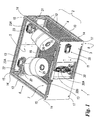
- a modular creel element is generically indicated in 1 and includes a structure 2 (in the example with solid polygon) with opposite sides 3 (front), 4, 5 (back) and 6, an upper 7 and lower 8 face; the lower face 8 can be defined from a flat grid 10 or, alternatively, transparent while the front side 3 supports a plane 11 the function of which will be described subsequently. The function of plane 10 will be subsequently described.
- the structure 2 is delimited in particular by sections (or profiles) 13 mechanically coupled together.
- seats or recesses 15 are provided, while pins (not shown) protrude lower down from corners 17 of the lower face 8. This allows overlapping stably (or placing side by side) two identical structures 2 inserting the aforesaid pins of the face 8 within the seats 15 of that face 7 (as shown in figure 3 ).
- other devices may be provided for connecting between identical structures 2, other than mechanical ones (such as magnetic devices) that also permit the lateral connection of the structures.
- the whole of the structures can constitute a complex matrix or "molecular” structure where the individual "atoms" are constituted by the structures 2 coupled together.
- arms 22 and 23 are located, respectively, hinged preferably to such posts and provided with hand grips 22A, 23A.
- Said arms that can rotate inside and outside of an internal cavity 19 of the structure 2, are suitable to support at least one spool or yarn reel 25 and 26. Due to such movement, an operator can easily replace the empty spools with full spools or intervene on the thread if it broke during feeding.
- the head of the thread of the latter is connected to a feeder device of the thread, known in itself, 30 associated with the plane 11 connected to the front side 3 of the structure 2, said thread for instance passing through a hole 31 provided in such a plane to reach said feeder device 30.
- the latter is preferably of the type suitable to feed the thread to a textile machine, in continuous or discontinuous fashion, with constant tension and/or speed, said control is effected by this same device 30. Obviously, this device can be set in another position on the structure 2.
- the feeder device introduces, in a known fashion, a rotating actuator 30A connected to a control unit for the operation of the device 30 (not shown) and a tension sensor device 30B.
- a rotating actuator 30A connected to a control unit for the operation of the device 30 (not shown) and a tension sensor device 30B.
- Such sensor device and said actuator together with the control unit, define a closed control loop for the feeding of the thread.
- a sensor device is present 33 suited to receive, passing through, the tail of the thread from spool 25 connected to the head of the thread from spool 26 (or vice versa).
- a device 33 is preferably connected to the control unit of the feeder device 30.
- the sensor device 33 can be provided with a yarn guide (for instance open) and be embodied in such a way as to allow the feeding of the device 30 with the thread from spool 26 when the thread from spool 25 runs out.
- the thread fed (coming from the full spool 26) is released from the sensor device 33 and this causes the device to produce a signal sent to a control unit 35 (possibly inserted into device 30 and coincident with or connected with such unit of said device 30) with display associated with the structure 2 that supervises the operation of the modular element 1 in all its components (spools and device 30).
- a control unit 35 possibly inserted into device 30 and coincident with or connected with such unit of said device 30
- Such signal produces, therefore, in the unit 35 a warning that the spool 25 has run out, which activates an alarm signal, visual or auditory (not shown), so as to involve the intervention of an operator.
- the operator removes the arm 22 carrying the empty spool 25 from the hollow 19 of the structure, rotating it around the respective post 20.
- This arm is arranged externally in the hollow so that what remains of the spool can be removed (the usual tubular support for the thread 40) and a new full spool 25 can be inserted on it.
- the device sensor 33 is "rearmed” by making the thread tail of spool 26 or the thread head of the new spool 25 pass through it.
- a creel of any dimensions can be obtained, chosen at will based on the operation of the requirement, by simply overlapping or placing side by side to each other a plurality of elements 1 (possibly and preferably they may be also mechanically coupled together through clamps, screws or bolts or male/female or magnetic couplings).
- the creel thus obtained includes a plurality of autonomous elements, independent both from the point of view of the spools they support (and replaceable independently between them without stopping the operation of the textile machine to which a plurality of threads is fed coming from the plurality of coupled creel elements) and from the point of view of the control of the feeding of the thread from each modular element.
- the aforesaid creel therefore composed from the elements 1 each capable to feed a single thread, allows a greater flexibility both in the production phase (production of a single element, always equal) and for the client that can add or remove an element without having to disturb the entire creel.
- Each of the elements of creel 1 includes besides the means (the sensor device 33 or analogous elements to detect the presence of the thread on the spool, including optical ones) to detect the end of the thread from a spool (or from a plurality of spools in association with an arm, either fixed or preferably and advantageously mobile 22 or 23) and to advise that, precisely, one spool (or plurality of spools) is to be replaced with a thread load.
- Every element 1 foresees an independent feeding device of the thread at constant tension, comprising a motor, a control electronics and a tension sensor.
- Such an element 1 is therefore capable to feed said thread independently at constant tension under the outline conditions (varying frictions, differences of tension on input between full spool and empty spool, absorption of speed variations, etc. It is therefore an element 1 that works in closed loop keeping the output tension constant, with consequent increase in the finished product quality. Since every element is equipped with a "smart" and independent feeding device (it operates in closed loop), it does not require any synchronization with the textile machine to which the thread is fed and is able to follow autonomously every speed variation of the production process with consequent marked simplification of the process itself.
- Every element 1 is besides equipped with a smart and independent feeding device (it works in closed loop) it is possible to plan for every element of a modular creel (including a plurality of such creel elements) and therefore for every thread fed to a textile machine, different job tensions and therefore different drawings, allowing maximum flexibility and therefore the creation of innovative articles.
- Such predetermined tensions could be constant for the entire job or based on the operational phase, there could be for instance a lower tension for the first feeding phase (start up of the machine) and, after a certain time after the start of the feed or a certain amount of thread fed or after a preset feed velocity, such tension could pass to a second value (generally higher) for the production phase; this in fully automatic fashion.
- the tensions could also vary during the production phase for instance following a pre-determined profile based on the manufactured article.
- the invention operates therefore in closed loop on the tension, therefore guaranteeing a greater precision of the control and it does not necessarily have to have any interfacing with the textile machine, simplifying therefore the installation and the management of the entire system; which is different for instance from US6676054 .
- creel element 1 described can also contain in its hollow 19 a single spool (or plurality of spools) supported by a mobile or fixed arm solidly attached to the structure 2 of such element. Obviously such an arm can also be external to the structure 2.
- An element 1 of the described type if connected through the unit 35 to a control unit of the textile machine, can stop this latter in the case of a rupture is detected of the thread fed to the device 30, a wrong feed tension or the lack of thread on the sensor device 30, guaranteeing a constancy in the production quality of manufactured articles and avoiding additional costs connected to possible defects noted on the products after their realization.
- plane 10 functions as of separation and protection element between overlapped structures 2 suited to prevent that the yarn spools or the yarn itself of a first structure 2 can interfere with the functionality of the underlying or in general adjacent element 1.
- the information detected by the sensor 33 and sent to the unit 35 can be sent to a remote control unit suitable to collect the information of the end of thread occurring on one spool (25, 26) and the start of using the thread from the other spool (25, 26), said information being used for producing a warning of end of thread on such spool and to activate an automated device for replacement of the finished spool, the information being also usable to gather data related to the number of spools used and finished or to associate the production batch with a particular batch of thread to guarantee the traceability of what is produced.
Landscapes
- Engineering & Computer Science (AREA)
- Quality & Reliability (AREA)
- Tension Adjustment In Filamentary Materials (AREA)
- Unwinding Of Filamentary Materials (AREA)
- Looms (AREA)
- Coupling Device And Connection With Printed Circuit (AREA)
- Optical Couplings Of Light Guides (AREA)
- Headphones And Earphones (AREA)
- Spinning Or Twisting Of Yarns (AREA)
Applications Claiming Priority (2)
| Application Number | Priority Date | Filing Date | Title |
|---|---|---|---|
| ITMI2009A002042A IT1396931B1 (it) | 2009-11-20 | 2009-11-20 | Elemento modulare di cantra. |
| PCT/IB2010/002948 WO2011061602A1 (en) | 2009-11-20 | 2010-11-18 | Modular element of creel |
Publications (2)
| Publication Number | Publication Date |
|---|---|
| EP2501634A1 EP2501634A1 (en) | 2012-09-26 |
| EP2501634B1 true EP2501634B1 (en) | 2013-07-24 |
Family
ID=42797553
Family Applications (1)
| Application Number | Title | Priority Date | Filing Date |
|---|---|---|---|
| EP20100788131 Active EP2501634B1 (en) | 2009-11-20 | 2010-11-18 | Modular element of creel |
Country Status (7)
| Country | Link |
|---|---|
| US (1) | US9067755B2 (enExample) |
| EP (1) | EP2501634B1 (enExample) |
| JP (1) | JP5752703B2 (enExample) |
| CN (1) | CN102666334B (enExample) |
| ES (1) | ES2432074T3 (enExample) |
| IT (1) | IT1396931B1 (enExample) |
| WO (1) | WO2011061602A1 (enExample) |
Families Citing this family (11)
| Publication number | Priority date | Publication date | Assignee | Title |
|---|---|---|---|---|
| US9132987B2 (en) | 2011-11-04 | 2015-09-15 | The Procter & Gamble Plaza | Apparatus with rotatable arm for unwinding strands of material |
| US9051151B2 (en) | 2011-11-04 | 2015-06-09 | The Procter & Gamble Company | Splicing apparatus for unwinding strands of material |
| ITMI20121929A1 (it) * | 2012-11-14 | 2014-05-15 | Btsr Int Spa | Elemento modulare per cantra |
| WO2015142565A1 (en) | 2014-03-17 | 2015-09-24 | The Procter & Gamble Company | Apparatus and method for manufacturing absorbent articles |
| ITUB20152769A1 (it) * | 2015-08-03 | 2017-02-03 | Btsr Int Spa | Alimentatore di filo ad accumulo con organo frenante e elementi intercambiabili |
| DE102016001957A1 (de) * | 2016-02-19 | 2017-08-24 | Saurer Germany Gmbh & Co. Kg | Vorzwirnspindelsegment, Vorzwirnspindeleinheit und Verfahren zum Aufbau einer zweistufigen Zwirn- oder Kabliermaschine |
| US10590581B1 (en) * | 2017-08-08 | 2020-03-17 | Robert S. Weiner | Compact creel construction |
| US11242216B2 (en) | 2018-08-28 | 2022-02-08 | Gary M McComas | Yarn tension and breakage sensor system |
| USD938499S1 (en) * | 2019-05-14 | 2021-12-14 | Btsr International S.P.A. | Modular creel |
| BE1028478B1 (nl) * | 2020-07-14 | 2022-02-15 | Gilbos N V | Verbeterde inrichting voor het houden van een bobijn met garen ter voorziening in een creel, en systeem daarvoor |
| WO2022021306A1 (zh) * | 2020-07-31 | 2022-02-03 | 江苏国望高科纤维有限公司 | 一种纱线假捻加弹的生产方法及纱线假捻加弹过程中过尾接头的检测方法 |
Family Cites Families (17)
| Publication number | Priority date | Publication date | Assignee | Title |
|---|---|---|---|---|
| US3432117A (en) * | 1967-05-24 | 1969-03-11 | Union Carbide Corp | Modular creel apparatus including strand guides |
| US3452947A (en) | 1967-07-07 | 1969-07-01 | Singer Co | Modular creel |
| JPS5255755A (en) * | 1975-11-04 | 1977-05-07 | Toray Industries | Driving method of drum car |
| DE2622443A1 (de) * | 1976-05-20 | 1977-12-08 | Schlafhorst & Co W | Textilmaschine mit arbeitsstellen zur herstellung von auflaufspulen |
| US4299359A (en) * | 1979-03-22 | 1981-11-10 | Alan Shelton Limited | Yarn bobbin support apparatus |
| BR8500013A (pt) | 1985-01-04 | 1985-07-02 | Pirelli Brasil | Modulo desenrolador para acondicionamento de carreteis contendo condutores eletricos |
| US5624082A (en) * | 1995-09-11 | 1997-04-29 | Ligon; Lang S. | In-line yarn feed creel |
| US6116292A (en) * | 1996-04-17 | 2000-09-12 | N.V. Michel Van De Wiele | Bobbin pallets for a weaving device |
| JP4651817B2 (ja) * | 1998-10-09 | 2011-03-16 | バルマーク アクチエンゲゼルシヤフト | 糸を連続的に繰出すための方法 |
| CN1267331C (zh) * | 2000-04-27 | 2006-08-02 | 帝人株式会社 | 纤维加工管理方法及纤维加工管理装置 |
| US6676054B2 (en) * | 2001-03-23 | 2004-01-13 | E. I. Du Pont De Nemours And Company | Unwinder for as-spun elastomeric fiber |
| ITMI20051325A1 (it) | 2005-07-12 | 2007-01-13 | Btsr Int Spa | Metodo e dispositivo per assicurare l'alimentazione di un filo a tensione costante a doppio anello di regolazione ad una macchina tessile |
| JP4731234B2 (ja) | 2005-07-25 | 2011-07-20 | 株式会社ブリヂストン | コードの乾燥処理方法と、その装置 |
| EP1954860B1 (en) * | 2005-10-11 | 2014-03-26 | Invista Technologies S.à.r.l. | A compact single mandrel creel for over end take-off thread delivery |
| WO2007079264A2 (en) * | 2005-12-30 | 2007-07-12 | Overend Technologies, Llc | Unwind and feed system for elastomeric thread |
| US7866595B2 (en) * | 2007-01-19 | 2011-01-11 | Automated Creel Systems, Inc. | Pivoting package support |
| US20080283653A1 (en) | 2007-04-20 | 2008-11-20 | Invista North America Sarl | Compact continuous over end take-off (oeto) creel with tension control |
-
2009
- 2009-11-20 IT ITMI2009A002042A patent/IT1396931B1/it active
-
2010
- 2010-11-18 JP JP2012539428A patent/JP5752703B2/ja active Active
- 2010-11-18 CN CN2010800501611A patent/CN102666334B/zh active Active
- 2010-11-18 US US13/508,267 patent/US9067755B2/en active Active
- 2010-11-18 WO PCT/IB2010/002948 patent/WO2011061602A1/en not_active Ceased
- 2010-11-18 EP EP20100788131 patent/EP2501634B1/en active Active
- 2010-11-18 ES ES10788131T patent/ES2432074T3/es active Active
Also Published As
| Publication number | Publication date |
|---|---|
| JP2013511456A (ja) | 2013-04-04 |
| WO2011061602A1 (en) | 2011-05-26 |
| US9067755B2 (en) | 2015-06-30 |
| EP2501634A1 (en) | 2012-09-26 |
| IT1396931B1 (it) | 2012-12-20 |
| US20120217337A1 (en) | 2012-08-30 |
| CN102666334A (zh) | 2012-09-12 |
| CN102666334B (zh) | 2013-11-13 |
| ES2432074T3 (es) | 2013-11-29 |
| ITMI20092042A1 (it) | 2011-05-21 |
| JP5752703B2 (ja) | 2015-07-22 |
Similar Documents
| Publication | Publication Date | Title |
|---|---|---|
| EP2501634B1 (en) | Modular element of creel | |
| US7896282B2 (en) | Double control loop method and device for ensuring constant tension yarn feed to a textile machine | |
| ITMI20100887A1 (it) | Metodo e dispositivo perfezionato per alimentare un filo ad una macchina operatrice con tensione e velocita' costante | |
| CN106012362B (zh) | 高精度剪线的绣花机剪线装置及方法 | |
| JP2014518825A (ja) | 一定の張力と一定の速度又は量で糸を繊維機械に供給する方法及び装置 | |
| ITMI20070149A1 (it) | Dispositivo di giuntura di fili per una macchina tessile producente bobine incrociate | |
| EP2907781A1 (de) | Verfahren, Vorrichtung und Computerprogramm zur Fadenendeauflösung für Spleißer | |
| EP1954860B1 (en) | A compact single mandrel creel for over end take-off thread delivery | |
| JP2013511456A5 (enExample) | ||
| KR20240162161A (ko) | 스레드의 인-라인 처리를 위한 방법, 및 처리 유닛 및 스레드 속도 센서를 포함하는 시스템 | |
| CZ2019198A3 (cs) | Způsob řízení prostředků pracovního místa textilního stroje a zařízení k jeho provádění | |
| JP6486330B2 (ja) | 弾性糸の供給におけるドラフト制御のためのプロセス | |
| CN104781172B (zh) | 用于线轴架的模块化的元件 | |
| CS210059B1 (en) | Device for the control,adjustment and regulation of the working place e.g.textile production unit or machine with the said units | |
| WO2018146582A1 (en) | Modular element for a creel with rotating bobbin support | |
| TWI453313B (zh) | 圖樣整經機(一) | |
| JP2010228852A (ja) | 糸継機構及びそれを用いたサンプル整経機 | |
| TWI620845B (zh) | 監測紡織機之產品的方法及裝置和紡織機 | |
| US5058398A (en) | Thread supply device for a circular knitting machine | |
| DE3827380C2 (enExample) | ||
| CZ292980B6 (cs) | Zařízení pro výrobu složkové příze a zařízení pro sledování alespoň jednoho parametru vypřádané složkové příze | |
| US20240246789A1 (en) | Winding machine for raffia spools | |
| WO2001034883A2 (es) | Sistema de control electronico para dispositivos de empalme de maquinas automaticas de hilatura por rotor | |
| KR101538887B1 (ko) | 텐션지지축이 유동하는 보빈와인더 | |
| KR20130010269A (ko) | 속도조절이 가능한 보빈 권사장치 |
Legal Events
| Date | Code | Title | Description |
|---|---|---|---|
| PUAI | Public reference made under article 153(3) epc to a published international application that has entered the european phase |
Free format text: ORIGINAL CODE: 0009012 |
|
| 17P | Request for examination filed |
Effective date: 20120419 |
|
| AK | Designated contracting states |
Kind code of ref document: A1 Designated state(s): AL AT BE BG CH CY CZ DE DK EE ES FI FR GB GR HR HU IE IS IT LI LT LU LV MC MK MT NL NO PL PT RO RS SE SI SK SM TR |
|
| DAX | Request for extension of the european patent (deleted) | ||
| GRAP | Despatch of communication of intention to grant a patent |
Free format text: ORIGINAL CODE: EPIDOSNIGR1 |
|
| GRAS | Grant fee paid |
Free format text: ORIGINAL CODE: EPIDOSNIGR3 |
|
| GRAA | (expected) grant |
Free format text: ORIGINAL CODE: 0009210 |
|
| AK | Designated contracting states |
Kind code of ref document: B1 Designated state(s): AL AT BE BG CH CY CZ DE DK EE ES FI FR GB GR HR HU IE IS IT LI LT LU LV MC MK MT NL NO PL PT RO RS SE SI SK SM TR |
|
| REG | Reference to a national code |
Ref country code: GB Ref legal event code: FG4D |
|
| REG | Reference to a national code |
Ref country code: CH Ref legal event code: EP |
|
| REG | Reference to a national code |
Ref country code: AT Ref legal event code: REF Ref document number: 623300 Country of ref document: AT Kind code of ref document: T Effective date: 20130815 |
|
| REG | Reference to a national code |
Ref country code: IE Ref legal event code: FG4D |
|
| REG | Reference to a national code |
Ref country code: DE Ref legal event code: R096 Ref document number: 602010008934 Country of ref document: DE Effective date: 20130919 |
|
| REG | Reference to a national code |
Ref country code: CH Ref legal event code: NV Representative=s name: R. A. EGLI AND CO. PATENTANWAELTE, CH |
|
| REG | Reference to a national code |
Ref country code: SE Ref legal event code: TRGR |
|
| REG | Reference to a national code |
Ref country code: AT Ref legal event code: MK05 Ref document number: 623300 Country of ref document: AT Kind code of ref document: T Effective date: 20130724 |
|
| REG | Reference to a national code |
Ref country code: NL Ref legal event code: VDEP Effective date: 20130724 |
|
| REG | Reference to a national code |
Ref country code: LT Ref legal event code: MG4D |
|
| PG25 | Lapsed in a contracting state [announced via postgrant information from national office to epo] |
Ref country code: CY Free format text: LAPSE BECAUSE OF FAILURE TO SUBMIT A TRANSLATION OF THE DESCRIPTION OR TO PAY THE FEE WITHIN THE PRESCRIBED TIME-LIMIT Effective date: 20130911 Ref country code: AT Free format text: LAPSE BECAUSE OF FAILURE TO SUBMIT A TRANSLATION OF THE DESCRIPTION OR TO PAY THE FEE WITHIN THE PRESCRIBED TIME-LIMIT Effective date: 20130724 Ref country code: PT Free format text: LAPSE BECAUSE OF FAILURE TO SUBMIT A TRANSLATION OF THE DESCRIPTION OR TO PAY THE FEE WITHIN THE PRESCRIBED TIME-LIMIT Effective date: 20131125 Ref country code: NO Free format text: LAPSE BECAUSE OF FAILURE TO SUBMIT A TRANSLATION OF THE DESCRIPTION OR TO PAY THE FEE WITHIN THE PRESCRIBED TIME-LIMIT Effective date: 20131024 Ref country code: IS Free format text: LAPSE BECAUSE OF FAILURE TO SUBMIT A TRANSLATION OF THE DESCRIPTION OR TO PAY THE FEE WITHIN THE PRESCRIBED TIME-LIMIT Effective date: 20131124 Ref country code: HR Free format text: LAPSE BECAUSE OF FAILURE TO SUBMIT A TRANSLATION OF THE DESCRIPTION OR TO PAY THE FEE WITHIN THE PRESCRIBED TIME-LIMIT Effective date: 20130724 Ref country code: LT Free format text: LAPSE BECAUSE OF FAILURE TO SUBMIT A TRANSLATION OF THE DESCRIPTION OR TO PAY THE FEE WITHIN THE PRESCRIBED TIME-LIMIT Effective date: 20130724 |
|
| PG25 | Lapsed in a contracting state [announced via postgrant information from national office to epo] |
Ref country code: FI Free format text: LAPSE BECAUSE OF FAILURE TO SUBMIT A TRANSLATION OF THE DESCRIPTION OR TO PAY THE FEE WITHIN THE PRESCRIBED TIME-LIMIT Effective date: 20130724 Ref country code: SI Free format text: LAPSE BECAUSE OF FAILURE TO SUBMIT A TRANSLATION OF THE DESCRIPTION OR TO PAY THE FEE WITHIN THE PRESCRIBED TIME-LIMIT Effective date: 20130724 Ref country code: PL Free format text: LAPSE BECAUSE OF FAILURE TO SUBMIT A TRANSLATION OF THE DESCRIPTION OR TO PAY THE FEE WITHIN THE PRESCRIBED TIME-LIMIT Effective date: 20130724 Ref country code: LV Free format text: LAPSE BECAUSE OF FAILURE TO SUBMIT A TRANSLATION OF THE DESCRIPTION OR TO PAY THE FEE WITHIN THE PRESCRIBED TIME-LIMIT Effective date: 20130724 Ref country code: GR Free format text: LAPSE BECAUSE OF FAILURE TO SUBMIT A TRANSLATION OF THE DESCRIPTION OR TO PAY THE FEE WITHIN THE PRESCRIBED TIME-LIMIT Effective date: 20131025 Ref country code: NL Free format text: LAPSE BECAUSE OF FAILURE TO SUBMIT A TRANSLATION OF THE DESCRIPTION OR TO PAY THE FEE WITHIN THE PRESCRIBED TIME-LIMIT Effective date: 20130724 |
|
| PG25 | Lapsed in a contracting state [announced via postgrant information from national office to epo] |
Ref country code: CY Free format text: LAPSE BECAUSE OF FAILURE TO SUBMIT A TRANSLATION OF THE DESCRIPTION OR TO PAY THE FEE WITHIN THE PRESCRIBED TIME-LIMIT Effective date: 20130724 |
|
| PG25 | Lapsed in a contracting state [announced via postgrant information from national office to epo] |
Ref country code: CZ Free format text: LAPSE BECAUSE OF FAILURE TO SUBMIT A TRANSLATION OF THE DESCRIPTION OR TO PAY THE FEE WITHIN THE PRESCRIBED TIME-LIMIT Effective date: 20130724 Ref country code: EE Free format text: LAPSE BECAUSE OF FAILURE TO SUBMIT A TRANSLATION OF THE DESCRIPTION OR TO PAY THE FEE WITHIN THE PRESCRIBED TIME-LIMIT Effective date: 20130724 Ref country code: RO Free format text: LAPSE BECAUSE OF FAILURE TO SUBMIT A TRANSLATION OF THE DESCRIPTION OR TO PAY THE FEE WITHIN THE PRESCRIBED TIME-LIMIT Effective date: 20130724 Ref country code: SK Free format text: LAPSE BECAUSE OF FAILURE TO SUBMIT A TRANSLATION OF THE DESCRIPTION OR TO PAY THE FEE WITHIN THE PRESCRIBED TIME-LIMIT Effective date: 20130724 Ref country code: DK Free format text: LAPSE BECAUSE OF FAILURE TO SUBMIT A TRANSLATION OF THE DESCRIPTION OR TO PAY THE FEE WITHIN THE PRESCRIBED TIME-LIMIT Effective date: 20130724 |
|
| PLBE | No opposition filed within time limit |
Free format text: ORIGINAL CODE: 0009261 |
|
| STAA | Information on the status of an ep patent application or granted ep patent |
Free format text: STATUS: NO OPPOSITION FILED WITHIN TIME LIMIT |
|
| 26N | No opposition filed |
Effective date: 20140425 |
|
| PG25 | Lapsed in a contracting state [announced via postgrant information from national office to epo] |
Ref country code: MC Free format text: LAPSE BECAUSE OF FAILURE TO SUBMIT A TRANSLATION OF THE DESCRIPTION OR TO PAY THE FEE WITHIN THE PRESCRIBED TIME-LIMIT Effective date: 20130724 |
|
| REG | Reference to a national code |
Ref country code: DE Ref legal event code: R097 Ref document number: 602010008934 Country of ref document: DE Effective date: 20140425 |
|
| REG | Reference to a national code |
Ref country code: IE Ref legal event code: MM4A |
|
| PG25 | Lapsed in a contracting state [announced via postgrant information from national office to epo] |
Ref country code: IE Free format text: LAPSE BECAUSE OF NON-PAYMENT OF DUE FEES Effective date: 20131118 |
|
| PG25 | Lapsed in a contracting state [announced via postgrant information from national office to epo] |
Ref country code: SM Free format text: LAPSE BECAUSE OF FAILURE TO SUBMIT A TRANSLATION OF THE DESCRIPTION OR TO PAY THE FEE WITHIN THE PRESCRIBED TIME-LIMIT Effective date: 20130724 |
|
| PG25 | Lapsed in a contracting state [announced via postgrant information from national office to epo] |
Ref country code: LU Free format text: LAPSE BECAUSE OF NON-PAYMENT OF DUE FEES Effective date: 20131118 Ref country code: HU Free format text: LAPSE BECAUSE OF FAILURE TO SUBMIT A TRANSLATION OF THE DESCRIPTION OR TO PAY THE FEE WITHIN THE PRESCRIBED TIME-LIMIT; INVALID AB INITIO Effective date: 20101118 Ref country code: MK Free format text: LAPSE BECAUSE OF FAILURE TO SUBMIT A TRANSLATION OF THE DESCRIPTION OR TO PAY THE FEE WITHIN THE PRESCRIBED TIME-LIMIT Effective date: 20130724 Ref country code: RS Free format text: LAPSE BECAUSE OF FAILURE TO SUBMIT A TRANSLATION OF THE DESCRIPTION OR TO PAY THE FEE WITHIN THE PRESCRIBED TIME-LIMIT Effective date: 20131024 Ref country code: BG Free format text: LAPSE BECAUSE OF FAILURE TO SUBMIT A TRANSLATION OF THE DESCRIPTION OR TO PAY THE FEE WITHIN THE PRESCRIBED TIME-LIMIT Effective date: 20130724 |
|
| PG25 | Lapsed in a contracting state [announced via postgrant information from national office to epo] |
Ref country code: MT Free format text: LAPSE BECAUSE OF FAILURE TO SUBMIT A TRANSLATION OF THE DESCRIPTION OR TO PAY THE FEE WITHIN THE PRESCRIBED TIME-LIMIT Effective date: 20130724 |
|
| REG | Reference to a national code |
Ref country code: FR Ref legal event code: PLFP Year of fee payment: 6 |
|
| REG | Reference to a national code |
Ref country code: FR Ref legal event code: PLFP Year of fee payment: 7 |
|
| REG | Reference to a national code |
Ref country code: FR Ref legal event code: PLFP Year of fee payment: 8 |
|
| PG25 | Lapsed in a contracting state [announced via postgrant information from national office to epo] |
Ref country code: AL Free format text: LAPSE BECAUSE OF FAILURE TO SUBMIT A TRANSLATION OF THE DESCRIPTION OR TO PAY THE FEE WITHIN THE PRESCRIBED TIME-LIMIT Effective date: 20130724 |
|
| P01 | Opt-out of the competence of the unified patent court (upc) registered |
Effective date: 20230626 |
|
| PGFP | Annual fee paid to national office [announced via postgrant information from national office to epo] |
Ref country code: DE Payment date: 20241127 Year of fee payment: 15 |
|
| PGFP | Annual fee paid to national office [announced via postgrant information from national office to epo] |
Ref country code: BE Payment date: 20241127 Year of fee payment: 15 |
|
| PGFP | Annual fee paid to national office [announced via postgrant information from national office to epo] |
Ref country code: GB Payment date: 20241127 Year of fee payment: 15 |
|
| PGFP | Annual fee paid to national office [announced via postgrant information from national office to epo] |
Ref country code: FR Payment date: 20241128 Year of fee payment: 15 |
|
| PGFP | Annual fee paid to national office [announced via postgrant information from national office to epo] |
Ref country code: IT Payment date: 20241024 Year of fee payment: 15 Ref country code: ES Payment date: 20241202 Year of fee payment: 15 |
|
| PGFP | Annual fee paid to national office [announced via postgrant information from national office to epo] |
Ref country code: SE Payment date: 20241127 Year of fee payment: 15 |
|
| PGFP | Annual fee paid to national office [announced via postgrant information from national office to epo] |
Ref country code: CH Payment date: 20241201 Year of fee payment: 15 |
|
| PGFP | Annual fee paid to national office [announced via postgrant information from national office to epo] |
Ref country code: TR Payment date: 20241108 Year of fee payment: 15 |
|
| REG | Reference to a national code |
Ref country code: CH Ref legal event code: U11 Free format text: ST27 STATUS EVENT CODE: U-0-0-U10-U11 (AS PROVIDED BY THE NATIONAL OFFICE) Effective date: 20251201 |