EP2500533A2 - Combustion engine with mixed cam shaft - Google Patents
Combustion engine with mixed cam shaft Download PDFInfo
- Publication number
- EP2500533A2 EP2500533A2 EP12001347A EP12001347A EP2500533A2 EP 2500533 A2 EP2500533 A2 EP 2500533A2 EP 12001347 A EP12001347 A EP 12001347A EP 12001347 A EP12001347 A EP 12001347A EP 2500533 A2 EP2500533 A2 EP 2500533A2
- Authority
- EP
- European Patent Office
- Prior art keywords
- camshaft
- cam
- combustion engine
- internal combustion
- mixed
- Prior art date
- Legal status (The legal status is an assumption and is not a legal conclusion. Google has not performed a legal analysis and makes no representation as to the accuracy of the status listed.)
- Granted
Links
Images


Classifications
-
- F—MECHANICAL ENGINEERING; LIGHTING; HEATING; WEAPONS; BLASTING
- F01—MACHINES OR ENGINES IN GENERAL; ENGINE PLANTS IN GENERAL; STEAM ENGINES
- F01L—CYCLICALLY OPERATING VALVES FOR MACHINES OR ENGINES
- F01L13/00—Modifications of valve-gear to facilitate reversing, braking, starting, changing compression ratio, or other specific operations
- F01L13/0015—Modifications of valve-gear to facilitate reversing, braking, starting, changing compression ratio, or other specific operations for optimising engine performances by modifying valve lift according to various working parameters, e.g. rotational speed, load, torque
-
- F—MECHANICAL ENGINEERING; LIGHTING; HEATING; WEAPONS; BLASTING
- F01—MACHINES OR ENGINES IN GENERAL; ENGINE PLANTS IN GENERAL; STEAM ENGINES
- F01L—CYCLICALLY OPERATING VALVES FOR MACHINES OR ENGINES
- F01L1/00—Valve-gear or valve arrangements, e.g. lift-valve gear
- F01L1/02—Valve drive
- F01L1/026—Gear drive
-
- F—MECHANICAL ENGINEERING; LIGHTING; HEATING; WEAPONS; BLASTING
- F01—MACHINES OR ENGINES IN GENERAL; ENGINE PLANTS IN GENERAL; STEAM ENGINES
- F01L—CYCLICALLY OPERATING VALVES FOR MACHINES OR ENGINES
- F01L1/00—Valve-gear or valve arrangements, e.g. lift-valve gear
- F01L1/34—Valve-gear or valve arrangements, e.g. lift-valve gear characterised by the provision of means for changing the timing of the valves without changing the duration of opening and without affecting the magnitude of the valve lift
-
- F—MECHANICAL ENGINEERING; LIGHTING; HEATING; WEAPONS; BLASTING
- F01—MACHINES OR ENGINES IN GENERAL; ENGINE PLANTS IN GENERAL; STEAM ENGINES
- F01L—CYCLICALLY OPERATING VALVES FOR MACHINES OR ENGINES
- F01L13/00—Modifications of valve-gear to facilitate reversing, braking, starting, changing compression ratio, or other specific operations
- F01L13/0015—Modifications of valve-gear to facilitate reversing, braking, starting, changing compression ratio, or other specific operations for optimising engine performances by modifying valve lift according to various working parameters, e.g. rotational speed, load, torque
- F01L13/0036—Modifications of valve-gear to facilitate reversing, braking, starting, changing compression ratio, or other specific operations for optimising engine performances by modifying valve lift according to various working parameters, e.g. rotational speed, load, torque the valves being driven by two or more cams with different shape, size or timing or a single cam profiled in axial and radial direction
- F01L13/0042—Modifications of valve-gear to facilitate reversing, braking, starting, changing compression ratio, or other specific operations for optimising engine performances by modifying valve lift according to various working parameters, e.g. rotational speed, load, torque the valves being driven by two or more cams with different shape, size or timing or a single cam profiled in axial and radial direction with cams being profiled in axial and radial direction
-
- F—MECHANICAL ENGINEERING; LIGHTING; HEATING; WEAPONS; BLASTING
- F01—MACHINES OR ENGINES IN GENERAL; ENGINE PLANTS IN GENERAL; STEAM ENGINES
- F01L—CYCLICALLY OPERATING VALVES FOR MACHINES OR ENGINES
- F01L1/00—Valve-gear or valve arrangements, e.g. lift-valve gear
- F01L1/12—Transmitting gear between valve drive and valve
- F01L1/18—Rocking arms or levers
- F01L1/185—Overhead end-pivot rocking arms
-
- F—MECHANICAL ENGINEERING; LIGHTING; HEATING; WEAPONS; BLASTING
- F01—MACHINES OR ENGINES IN GENERAL; ENGINE PLANTS IN GENERAL; STEAM ENGINES
- F01L—CYCLICALLY OPERATING VALVES FOR MACHINES OR ENGINES
- F01L1/00—Valve-gear or valve arrangements, e.g. lift-valve gear
- F01L1/20—Adjusting or compensating clearance
- F01L1/22—Adjusting or compensating clearance automatically, e.g. mechanically
- F01L1/24—Adjusting or compensating clearance automatically, e.g. mechanically by fluid means, e.g. hydraulically
- F01L1/2405—Adjusting or compensating clearance automatically, e.g. mechanically by fluid means, e.g. hydraulically by means of a hydraulic adjusting device located between the cylinder head and rocker arm
-
- F—MECHANICAL ENGINEERING; LIGHTING; HEATING; WEAPONS; BLASTING
- F01—MACHINES OR ENGINES IN GENERAL; ENGINE PLANTS IN GENERAL; STEAM ENGINES
- F01L—CYCLICALLY OPERATING VALVES FOR MACHINES OR ENGINES
- F01L1/00—Valve-gear or valve arrangements, e.g. lift-valve gear
- F01L1/34—Valve-gear or valve arrangements, e.g. lift-valve gear characterised by the provision of means for changing the timing of the valves without changing the duration of opening and without affecting the magnitude of the valve lift
- F01L1/344—Valve-gear or valve arrangements, e.g. lift-valve gear characterised by the provision of means for changing the timing of the valves without changing the duration of opening and without affecting the magnitude of the valve lift changing the angular relationship between crankshaft and camshaft, e.g. using helicoidal gear
-
- F—MECHANICAL ENGINEERING; LIGHTING; HEATING; WEAPONS; BLASTING
- F01—MACHINES OR ENGINES IN GENERAL; ENGINE PLANTS IN GENERAL; STEAM ENGINES
- F01L—CYCLICALLY OPERATING VALVES FOR MACHINES OR ENGINES
- F01L1/00—Valve-gear or valve arrangements, e.g. lift-valve gear
- F01L1/02—Valve drive
- F01L1/04—Valve drive by means of cams, camshafts, cam discs, eccentrics or the like
- F01L1/047—Camshafts
- F01L1/053—Camshafts overhead type
- F01L2001/0537—Double overhead camshafts [DOHC]
-
- F—MECHANICAL ENGINEERING; LIGHTING; HEATING; WEAPONS; BLASTING
- F01—MACHINES OR ENGINES IN GENERAL; ENGINE PLANTS IN GENERAL; STEAM ENGINES
- F01L—CYCLICALLY OPERATING VALVES FOR MACHINES OR ENGINES
- F01L1/00—Valve-gear or valve arrangements, e.g. lift-valve gear
- F01L1/34—Valve-gear or valve arrangements, e.g. lift-valve gear characterised by the provision of means for changing the timing of the valves without changing the duration of opening and without affecting the magnitude of the valve lift
- F01L1/344—Valve-gear or valve arrangements, e.g. lift-valve gear characterised by the provision of means for changing the timing of the valves without changing the duration of opening and without affecting the magnitude of the valve lift changing the angular relationship between crankshaft and camshaft, e.g. using helicoidal gear
- F01L2001/34486—Location and number of the means for changing the angular relationship
-
- F—MECHANICAL ENGINEERING; LIGHTING; HEATING; WEAPONS; BLASTING
- F01—MACHINES OR ENGINES IN GENERAL; ENGINE PLANTS IN GENERAL; STEAM ENGINES
- F01L—CYCLICALLY OPERATING VALVES FOR MACHINES OR ENGINES
- F01L13/00—Modifications of valve-gear to facilitate reversing, braking, starting, changing compression ratio, or other specific operations
- F01L13/0015—Modifications of valve-gear to facilitate reversing, braking, starting, changing compression ratio, or other specific operations for optimising engine performances by modifying valve lift according to various working parameters, e.g. rotational speed, load, torque
- F01L13/0036—Modifications of valve-gear to facilitate reversing, braking, starting, changing compression ratio, or other specific operations for optimising engine performances by modifying valve lift according to various working parameters, e.g. rotational speed, load, torque the valves being driven by two or more cams with different shape, size or timing or a single cam profiled in axial and radial direction
- F01L2013/0052—Modifications of valve-gear to facilitate reversing, braking, starting, changing compression ratio, or other specific operations for optimising engine performances by modifying valve lift according to various working parameters, e.g. rotational speed, load, torque the valves being driven by two or more cams with different shape, size or timing or a single cam profiled in axial and radial direction with cams provided on an axially slidable sleeve
-
- F—MECHANICAL ENGINEERING; LIGHTING; HEATING; WEAPONS; BLASTING
- F01—MACHINES OR ENGINES IN GENERAL; ENGINE PLANTS IN GENERAL; STEAM ENGINES
- F01L—CYCLICALLY OPERATING VALVES FOR MACHINES OR ENGINES
- F01L2305/00—Valve arrangements comprising rollers
Definitions
- the invention relates to an internal combustion engine, in particular a diesel engine, in particular a motor vehicle, with at least one working cylinder, wherein each cylinder at least two intake valves and at least one exhaust valve is assigned, wherein at least two camshafts are provided, of which at least one mixed camshaft both at least one inlet valve and actuated at least one exhaust valve, wherein at least one mixed camshaft which actuates both at least one inlet valve and at least one exhaust valve, a phaser is arranged which valve timing of the mixed camshaft associated intake and exhaust valves against the valve timing of the at least one other camshaft optional after Early or late adjusted, according to the preamble of claim 1.
- a valve train in which a cam carrier is arranged rotationally fixed and axially displaceable on a base camshaft.
- the cam carrier consists of a tubular material, on which at least one cam is arranged, in which emerge from a common base circle axially offset several different cam tracks.
- the object of the invention is to improve or optimize intake and / or exhaust gate times for the thermodynamic optimization of engine operation in the map.
- At least on the mixed camshaft at least one cam carrier is provided, wherein the cam carrier relative to this mixed camshaft rotatably and axially displaceably on the mixed camshaft is arranged, wherein the at least one cam carrier has at least one cam on which at least two different Cam tracks are formed, wherein means for axially displacing the at least one cam carrier relative to the mixed camshaft between a first axial position and at least one second axial position are provided.
- the at least two different cam tracks may be arranged axially spaced from each other and extend substantially parallel to each other.
- at least a first of the at least two different cam tracks may have a different course from a second of the at least two different cam tracks on the cam at a radial distance from the axis of the cam Have camshaft and / or in the circumferential direction of the mixed camshaft.
- a high mechanical stability with functional reliability of the cam carrier over many cycles is achieved by enclosing the at least one cam carrier for supporting the at least one camshaft of at least one cylinder head-fixed camshaft bearing.
- the mixed camshaft may in each case comprise at least one cam for one of the working cylinders, wherein the intake and exhaust valves associated with the mixed camshaft are simultaneously adjustable by actuation of the adjuster either early or late.
- a particularly well optimizable adaptation of valve timing to an operating state of the internal combustion engine is achieved in that the adjuster is designed such that it has an adjustment range for the valve timing of 60 ° CA +/- 20 °.
- the operation of the individual intake and exhaust valves in particular for a working cylinder, can be designed individually: at least one of the at least two different cam tracks on a cam for actuating an intake valve and at least one other of the at least two different cam tracks on a cam for actuating an exhaust valve different courses at a radial distance from the axis of the mixed.
- the cam tracks may have different profiles of their height as a function of the azimuthal angle to the axis of the mixed camshaft.
- the actuation of the individual intake and exhaust valves of an internal combustion engine with a plurality of working cylinders can be designed individually for individual working cylinders, in particular for the intake valves or for the exhaust valves: at least one of the at least two different cam tracks on one first cam for actuating an inlet or an outlet valve of a first working cylinder and at least one other of the at least two different cam tracks on a cam for actuating a on or Exhaust valve of a second working cylinder may have different courses at a radial distance from the axis of the mixed camshaft and / or in the circumferential direction of the mixed camshaft.
- the cam tracks may have different profiles of their height as a function of the azimuthal angle to the axis of the mixed camshaft.
- each cylinder two exhaust valves are assigned, wherein two camshafts are provided, wherein a first camshaft, one half of the intake and exhaust valves and a second camshaft, the other half of the Ein - And exhaust valves actuated, wherein the first camshaft fixed timing for the camshaft associated valves and is arranged on the second camshaft of the adjuster.
- a particularly large adjustment range, especially in diesel engines, without collision between valves and reciprocating piston is achieved in that the second camshaft is designed such that at an adjustment angle of 0 ° KW, the second camshaft associated exhaust valves close earlier than those associated with the first camshaft Open exhaust valves and the intake valves associated with the second cam later and later close than the intake valves associated with the first camshaft.
- thermodynamic optimization of the operation of the internal combustion engine is achieved in that the second camshaft is designed such that close at an adjustment angle of 0 ° KW, the intake valves associated with the second camshaft at the same time with the intake valves associated with the first camshaft. In this case, only a late adjustment takes place.
- a particularly simple and functionally reliable axial displacement of the cam carrier is achieved in that the means for axially displacing the at least one cam carrier relative to the mixed camshaft between a first axial position and at least a second axial position at least one axially fixed relative to the blended camshaft and radially between a first and a second pin position displaceable bolt which engages in the second pin position in a formed on the cam carrier, in the radial direction circumferential groove and spaced in the first pin position of this groove, wherein the groove is formed such that the cam carrier of an axial position on the mixed camshaft shifts to a different axial position on the mixed cam shaft when the bolt engages in the groove.
- a particularly fast and repeatable axial displacement of the cam carrier is achieved by providing at least one first pin which selectively engages a first groove and at least one second pin spaced axially with respect to the mixed cam shaft from the first pin engages the second groove spaced axially from the first groove with respect to the blended camshaft, wherein the cam carrier moves from the first axial position on the blended camshaft to the second axial position on the blended camshaft as the first bolt engages and disengages the first cam groove second axial position on the blended camshaft moves to the first axial position on the blended camshaft when the second bolt engages the second groove.
- the internal combustion engine may in particular be a diesel engine. It is preferably an internal combustion engine of a motor vehicle, in particular a trackless agricultural vehicle.
- an inventive internal combustion engine comprises a cylinder head 10, are arranged in the non-illustrated working cylinder, in which each have a reciprocating piston (not shown) oscillating moves.
- the cylinder head 10 has an outlet side 12, at which exhaust gases are discharged from the working cylinders, and an inlet side 14, at which the working cylinders fresh gas is supplied.
- Each cylinder is associated with two intake valves (not shown) and two exhaust valves (not shown), wherein a first camshaft 16 and a second camshaft 18 are provided.
- the first camshaft 16 carries inlet cams 20; each actuating an intake valve, and exhaust cams 22 each actuating an exhaust valve.
- the second camshaft 18 carries intake cams 24, each actuating an intake valve, and exhaust cams 26, each actuating an exhaust valve.
- intake cams 20, 24 and exhaust cams 22, 26 alternate as seen in the longitudinal direction. In this way, the two intake valves and exhaust valves of each working cylinder are actuated by different camshafts 16, 18.
- each of the camshafts 12, 14 is a so-called mixed camshaft, ie each camshaft 12, 14 actuates both intake and exhaust valves via respective intake cams 20, 24 and exhaust cams 22, 26, respectively.
- the timing of the first camshaft 16 for the associated intake and exhaust valves are fixed unchangeable.
- a phaser 28 which changes the timing of the intake and exhaust valves associated therewith with respect to the timing of the first camshaft 16 by rotating the second camshaft 18 by the phaser 28 relative to the first camshaft 16.
- the first camshaft 16 is the camshaft that is driven at 30 by a crankshaft, not shown, of the internal combustion engine.
- the first camshaft 16 in turn drives the second camshaft 18 via gears 32.
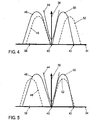
- FIG. 3 to 5 is on a horizontal axis 34, a crank angle and a vertical axis 36, a lifting movement applied.
- On the horizontal axis 34 is at 38 a bottom dead center (UT) of the reciprocating before.dem charge change, at 40 an upper dead center (TDC) of the reciprocating piston during the charge cycle and at 42 a bottom dead center (UT) of the reciprocating piston applied after the charge cycle.
- a first graph 44 illustrates the lift 36 across the crank angle 34 for the piston
- a second graph 46 illustrates the lift 36 over the crank 34 for those exhaust valves controlled by the exhaust cams 22 of the first cam 16
- a third graph 48 (dashed line) FIG.
- a fourth graph 50 illustrates the lift motion 36 versus the crank angle 34 for those intake valves that are from the intake cams 20 of the first camshaft 16 controlled and a fifth graph 52 (dashed) illustrates the lift 36 over the crank angle 34 for those intake valves controlled by the intake cams 24 of the second camshaft 18.
- Fig. 3 is a position of the adjuster 28 shown at 0 ° KW, ie, the camshafts 16, 18 are not rotated against each other.
- Fig. 4 is a position of the adjuster at maximum displacement towards late and in Fig. 5 is a position of the adjuster at maximum adjustment shown in the morning.
- the stroke of the valves of the first crankshaft 16 (second graph 46 and fourth graph 50) remains unchanged relative to the crankshaft, whereas the stroke of the valves of the second crankshaft 18 (third graph 48 and fifth graph 52 each dashed) together for the associated Inlet valves and exhaust valves are moved.
- the prerequisite for this simulated Miller is the presence of at least two intake valves per cylinder and one, preferably two exhaust valves per cylinder, the intake valves of each cylinder being actuated by different crankshafts.
- a camshaft 16 serves half of all intake and exhaust valves with conventional timing.
- the inlet side is optimized for maximum filling at a specific operating point, for example for the cold start operating point.
- the second camshaft 18 operates the remaining intake and exhaust valves and is with respect to the cam contour for "exhaust valve closes" and "inlet valve opens” designed so that an adjustment of this camshaft 18 of about 60 ° CA +/- 20 ° can take place without piston collision ,
- the Miller bulk is achieved in that the earliest "intake valve opens” associated with one camshaft 16 and the latest “intake valve closes” the other camshaft 18 different valves for each cylinder, see. Fig. 4 ,
- this can also be considered as 0 ° position for the second camshaft 18, so that then only a retardation occurs. It is important in any case, however, that the intake cam of the first camshaft 16 is shortened in such a way in comparison to UT, for example in diesel engines at about 10 ° -25 ° CA to UT, that the UT position ES can be achieved by both cams.
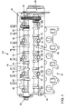
- FIG. 6 shows a portion of the second mixed camshaft 18, on which axially spaced, for example, four formed as a hollow shaft cam carrier 54 are arranged, wherein in Fig. 6 only one of the cam supports 54 is shown.
- the following description refers only to the illustrated cam carrier 54, but also applies to all other, not shown cam carrier on the second camshaft 18.
- the cam carrier 54 is axially displaceable on the second camshaft 18 but rotatably mounted.
- a worm drive with an axial curve 56 or 68 designed as a depression or groove, which winds helically about a cam carrier axis.
- the grooves 56, 58 extend circumferentially around the cam carrier 54.
- each cam piece 54 On the cam carrier 54, two cams are arranged, with each cam from the same base circle axially offset two different cam tracks 60, 62 and 64, 66 emerge.
- the cylindrical region of the lateral surface of each cam piece 54 located between the two cams is designed as a bearing surface for a camshaft bearing 68.
- Each cam carrier 54 is rotatably and axially displaceably mounted with this cylindrical bearing surface in a camshaft bearing block 68 of a cylinder head (not shown).
- the two camshaft bearing block 68 facing end faces of the cams are formed as contact surfaces 70 and 72. Accordingly, the cam-facing end faces of the camshaft bearing 68 are formed as a contact surface 74 and 76, respectively.
- the distance between the two contact surfaces 70 and 72 of the cams is greater than the distance between the contact surfaces 74 and 76 of the camshaft bearing 68.
- Gas exchange valve 78, 80 of the internal combustion engine are actuated by the cam via cam follower 82, 86, the Friction reduction with a roller 84 are formed.
- one gas exchange valve 78 is an inlet valve and the other gas exchange valve 80 is an outlet valve.
- the rocker arms 82, 86 is in a conventional known manner formed in the cylinder head clearance compensation element 88 and 90th
- the cam carrier 54 In the first position of the cam carrier 54, as in FIG Fig. 6 in which the contact surface 70 of the inlet cam 24 abuts the abutment surface 74 of the camshaft bearing 68, and in the second position of the cam carrier 54, in which the abutment surface 72 of the exhaust cam 26 abuts the abutment surface 76 of the camshaft bearing 68, the cam carrier 54 is respectively fixed in the axial direction by a releasable locking device, as in Fig. 6 is indicated in the broken outlet cam 26. In this way, the cam carrier 2 is fixed for both axial positions.
- cam carrier 54 arranged on the second camshaft 18 can in this way be adjusted individually by the associated actuators 94 and 98, respectively, between their two operating positions for the stroke valve control. According to the invention, such a configuration of the adjustment of the Hubventil penetrateung for a both intake valves controlling and exhaust valves controlling mixed camshaft 18 is provided with camshaft adjuster 28.
Landscapes
- Engineering & Computer Science (AREA)
- Mechanical Engineering (AREA)
- General Engineering & Computer Science (AREA)
- Valve Device For Special Equipments (AREA)
- Valve-Gear Or Valve Arrangements (AREA)
Abstract
Description
Die Erfindung betrifft eine Brennkraftmaschine, insbesondere Dieselmotor, insbesondere eines Kraftfahrzeugs, mit mindestens einem Arbeitszylinder, wobei jedem Arbeitszylinder mindestens zwei Einlassventile und mindestens ein Auslassventil zugeordnet ist, wobei mindestens zwei Nockenwellen vorgesehen sind, von denen wenigstens eine gemischte Nockenwelle sowohl mindestens ein Einlassventil als auch mindestens ein Auslassventil betätigt, wobei an mindestens einer gemischten Nockenwelle, die sowohl mindestens ein Einlassventil als auch mindestens ein Auslassventil betätigt, ein Versteller angeordnet ist, welcher Ventilsteuerzeiten der dieser gemischten Nockenwelle zugeordneten Ein- und Auslassventile gegenüber den Ventilsteuerzeiten der mindestens einen anderen Nockenwelle wahlweise nach Früh oder Spät verstellt, gemäß dem Oberbegriff des Patentanspruchs 1.The invention relates to an internal combustion engine, in particular a diesel engine, in particular a motor vehicle, with at least one working cylinder, wherein each cylinder at least two intake valves and at least one exhaust valve is assigned, wherein at least two camshafts are provided, of which at least one mixed camshaft both at least one inlet valve and actuated at least one exhaust valve, wherein at least one mixed camshaft which actuates both at least one inlet valve and at least one exhaust valve, a phaser is arranged which valve timing of the mixed camshaft associated intake and exhaust valves against the valve timing of the at least one other camshaft optional after Early or late adjusted, according to the preamble of claim 1.
Aus der
Beim bekannten Miller/Atkinson-Cycle wird der Zeitpunkt "Einlassventil schließt" (ES) nach spät verschoben. Auf diese Weise wird bereits im Zylinder befindliches Frischgas z.T. wieder ausgeschoben. Dies bedeutet einen Füllungsnachteil, der aber über eine Aufladung mit einem geeigneten Ladedruck kompensiert werden kann. Dabei ist der Ladedruck im Volumen zwischen Laderausgang und Motoreinlass so zu regeln, dass der Ladedruck in jedem Miller-Betriebspunkt, d.h. jeder Betriebspunkt in dem der "MillerCycle" zur Anwendung kommt, dem theoretischen Verdichtungsenddruck in den Arbeitszylindern der Brennkraftmaschine zum Zeitpunkt Einlassventil schließt entspricht. Für die Regelung, wahlweise auch Steuerung, kommen Druck- und/oder Temperatur- und/oder Massenstromsensoren oder sinnvolle Kombisensoren der drei angesprochenen Sensortypen zum Einsatz.In the well-known Miller / Atkinson cycle, the point in time "intake valve closes" (ES) is postponed. In this way, already in-cylinder fresh gas is z.T. pushed out again. This means a filling disadvantage, which can be compensated but via a charge with a suitable boost pressure. In this case, the charge pressure in the volume between the loader outlet and the engine inlet is to be controlled so that the boost pressure at each Miller operating point, i. each operating point in which the "MillerCycle" is used, corresponds to the theoretical compression end pressure in the working cylinders of the internal combustion engine at the time intake valve closes. For the control, optionally also control, come pressure and / or temperature and / or mass flow sensors or useful combination sensors of the three types of sensor used.
Der positive Effekt des Miller/Atkinson-Cycles mittels frühem oder spätem Zeitpunkt für das Schließen des Einlassventils auf die NOx-Emission und Homogenisierbarkeit des Dieselgemischs ist bekannt. Weiterhin kann bei ottomotorischen Anwendungen die Klopfneigung bei Hochaufladung deutlich reduziert werden. Im Gegensatz zum Ottomotor, der aufgrund fehlender geometrischer Zwänge mit positiver Ventilüberschneidung arbeiten kann, ist beim Dieselmotor eine einfache Umsetzung des Verfahrens mit Hilfe eines Phasenstellers generell nicht möglich. Grund hierfür ist eine mechanische Kollision des Ventils mit dem Kolben bei Frühverstellung und vermehrte Pumparbeit bei Spätverstellung.The positive effect of the Miller / Atkinson cycle on the NO x emission and homogenization of the diesel mixture by means of an early or late point in time for closing the inlet valve is known. Furthermore, in ottomotorischen applications Tapping tendency when charging high can be significantly reduced. In contrast to the gasoline engine, which can work due to lack of geometric constraints with positive valve overlap, in the diesel engine, a simple implementation of the method using a phaser is generally not possible. The reason for this is a mechanical collision of the valve with the piston during early adjustment and increased pumping work with retardation.
Aus den Druckschriften
Der Erfindung liegt die Aufgabe zugrunde, Einlass- und/oder Auslasseteuerzeiten zur thermodynamischen Optimierung des Motorbetriebs im Kennfeld zu verbessern bzw. zu optimieren.The object of the invention is to improve or optimize intake and / or exhaust gate times for the thermodynamic optimization of engine operation in the map.
Diese Aufgabe wird erfindungsgemäß durch eine Brennkraftmaschine der o.g. Art mit den in Anspruch 1 gekennzeichneten Merkmalen gelöst. Vorteilhafte Ausgestaltungen der Erfindung sind in den weiteren Ansprüchen beschrieben.This object is achieved by an internal combustion engine o.g. Art solved with the features characterized in claim 1. Advantageous embodiments of the invention are described in the further claims.
Dazu ist es bei einer Brennkraftmaschine der o.g. Art erfindungsgemäß vorgesehen, dass mindestens an der gemischten Nockenwelle mindestens ein Nockenträger vorgesehen ist, wobei der Nockenträger relativ zu dieser gemischten Nockenwelle drehfest und axial verschiebbar auf der gemischten Nockenwelle angeordnet ist, wobei der mindestens eine Nockenträger mindestens einen Nocken aufweist, auf dem mindestens zwei unterschiedliche Nockenlaufbahnen ausgebildet sind, wobei Mittel zum axialen Verschieben des mindestens einen Nockenträgers gegenüber der gemischten Nockenwelle zwischen einer ersten axialen Position und mindestens einer zweiten axialen Position vorgesehen sind.For this it is in an internal combustion engine o.g. Art provided according to the invention that at least on the mixed camshaft at least one cam carrier is provided, wherein the cam carrier relative to this mixed camshaft rotatably and axially displaceably on the mixed camshaft is arranged, wherein the at least one cam carrier has at least one cam on which at least two different Cam tracks are formed, wherein means for axially displacing the at least one cam carrier relative to the mixed camshaft between a first axial position and at least one second axial position are provided.
Die mindestens zwei unterschiedlichen Nockenlaufbahnen können voneinander axial beabstandet angeordnet sein und im Wesentlichen parallel zueinander verlaufen. Insbesondere kann wenigstens eine erste der wenigstens zwei unterschiedlichen Nockenlaufbahnen einen sich von einer zweiten der wenigstens zwei unterschiedlichen Nockenlaufbahnen auf dem Nocken einen unterscheidenden Verlauf in radialem Abstand von der Achse der gemischten Nockenwelle und/oder in Umfangsrichtung der gemischten Nockenwelle aufweisen.The at least two different cam tracks may be arranged axially spaced from each other and extend substantially parallel to each other. In particular, at least a first of the at least two different cam tracks may have a different course from a second of the at least two different cam tracks on the cam at a radial distance from the axis of the cam Have camshaft and / or in the circumferential direction of the mixed camshaft.
Dies hat den Vorteil, dass eine Nockenumschaltung mit reduzierter Anzahl von Nockenstellen zur Verfügung steht, da beispielsweise ein Steller sowohl einen Einlassnocken als auch einen Auslassnocken umstellt.This has the advantage that a cam switch with a reduced number of cam positions is available, since, for example, an actuator converts both an intake cam and an exhaust cam.
Eine hohe mechanische Stabilität mit über viele Zyklen funktionssicherer Verschlebbarkeit des Nockenträgers erzielt man dadurch, dass der mindestens eine Nockenträger zur Lagerung der mindestens einen Nockenwelle von mindestens einem zylinderkopffesten Nockenwellenlager umfasst ist.A high mechanical stability with functional reliability of the cam carrier over many cycles is achieved by enclosing the at least one cam carrier for supporting the at least one camshaft of at least one cylinder head-fixed camshaft bearing.
In Ausführungsformen, in denen die Brennkraftmaschine eine Mehrzahl von Arbeitszylindern aufweist, kann die gemischte Nockenwelle jeweils mindestens einen Nocken für einen der Arbeitszylinder umfassen, wobei die der gemischten Nockenwelle zugeordneten Ein- und Auslassventile gleichzeitig durch Betätigung des Verstellers wahlweise nach Früh oder Spät verstellbar sind.In embodiments in which the internal combustion engine has a plurality of working cylinders, the mixed camshaft may in each case comprise at least one cam for one of the working cylinders, wherein the intake and exhaust valves associated with the mixed camshaft are simultaneously adjustable by actuation of the adjuster either early or late.
Eine besonders gut optimierbare Anpassung von Ventilsteuerzeiten an einen Betriebszustand der Brennkraftmaschine wird dadurch erzielt, dass der Versteller derart ausgebildet, dass dieser einen Verstellbereich für die Ventilsteuerzeiten von 60°KW +/-20° aufweist.A particularly well optimizable adaptation of valve timing to an operating state of the internal combustion engine is achieved in that the adjuster is designed such that it has an adjustment range for the valve timing of 60 ° CA +/- 20 °.
Die Betätigung der einzelnen Ein- und Auslassventile, insbesondere für einen Arbeitszylinder, kann individuell gestaltet sein: Wenigstens eine der wenigstens zwei unterschiedlichen Nockenlaufbahnen auf einem Nocken zur Betätigung eines Einlassventils und wenigstens eine andere der wenigstens zwei unterschiedlichen Nockenlaufbahnen auf einem Nocken zur Betätigung eines Auslassventils können unterschiedliche Verläufe in radialem Abstand von der Achse der gemischten. Nockenwelle und/oder in Umfangsrichtung der gemischten Nockenwelle aufweisen. Anders gesagt, die Nockenlaufbahnen können unterschiedliche Verläufe ihrer Höhe in Funktion des Azimutalwinkels zur Achse der gemischten Nockenwelle aufweisen.The operation of the individual intake and exhaust valves, in particular for a working cylinder, can be designed individually: at least one of the at least two different cam tracks on a cam for actuating an intake valve and at least one other of the at least two different cam tracks on a cam for actuating an exhaust valve different courses at a radial distance from the axis of the mixed. Have camshaft and / or in the circumferential direction of the mixed camshaft. In other words, the cam tracks may have different profiles of their height as a function of the azimuthal angle to the axis of the mixed camshaft.
Des Weiteren oder alternativ dazu kann auch die Betätigung der einzelnen Ein- und Auslassventile einer Brennkraftmaschine mit einer Mehrzahl von Arbeitszylindern kann für einzelne Arbeitszylinder individuell, insbesondere jeweils für die Einlassventile oder für die Auslassventile, gestaltet sein: Wenigstens eine der wenigstens zwei unterschiedlichen Nockenlaufbahnen auf einem ersten Nocken zur Betätigung eines Ein- oder eines Auslassventils eines ersten Arbeitszylinders und wenigstens eine andere der wenigstens zwei unterschiedlichen Nockenlaufbahnen auf einem Nocken zur Betätigung eines Ein- oder Auslassventils eines zweiten Arbeitszylinders kann unterschiedliche Verläufe in radialem Abstand von der Achse der gemischten Nockenwelle und/oder in Umfangsrichtung der gemischten Nockenwelle aufweisen. Anders gesagt, die Nockenlaufbahnen können unterschiedliche Verläufe ihrer Höhe in Funktion des Azimutalwinkels zur Achse der gemischten Nockenwelle aufweisen.Furthermore or alternatively, the actuation of the individual intake and exhaust valves of an internal combustion engine with a plurality of working cylinders can be designed individually for individual working cylinders, in particular for the intake valves or for the exhaust valves: at least one of the at least two different cam tracks on one first cam for actuating an inlet or an outlet valve of a first working cylinder and at least one other of the at least two different cam tracks on a cam for actuating a on or Exhaust valve of a second working cylinder may have different courses at a radial distance from the axis of the mixed camshaft and / or in the circumferential direction of the mixed camshaft. In other words, the cam tracks may have different profiles of their height as a function of the azimuthal angle to the axis of the mixed camshaft.
Ein besonders guter und optimierter Gaswechsel während des Betriebs der Brennkraftmaschine wird dadurch erzielt, dass jedem Arbeitszylinder zwei Auslassventile zugeordnet sind, wobei zwei Nockenwellen vorgesehen sind, wobei eine erste Nockenwelle die eine Hälfte der Ein- und Auslassventile und eine zweite Nockenwelle die andere Hälfte der Ein- und Auslassventile betätigt, wobei die erste Nockenwelle feste Steuerzeiten für die dieser Nockenwelle zugeordneten Ventile aufweist und an der zweiten Nockenwelle der Versteller angeordnet ist.A particularly good and optimized gas exchange during operation of the internal combustion engine is achieved in that each cylinder two exhaust valves are assigned, wherein two camshafts are provided, wherein a first camshaft, one half of the intake and exhaust valves and a second camshaft, the other half of the Ein - And exhaust valves actuated, wherein the first camshaft fixed timing for the camshaft associated valves and is arranged on the second camshaft of the adjuster.
Ein besonders großer Verstellbereich, insbesondere auch bei Dieselmotoren, ohne Kollision zwischen Ventilen und Hubkolben wird dadurch erzielt, dass die zweite Nockenwelle derart ausgebildet ist, dass bei einem Verstellwinkel von 0°KW die der zweiten Nockenwelle zugeordneten Auslassventile früher schließen als die der ersten Nockenwelle zugeordneten Auslassventile und die der zweiten Nockenwelle zugeordneten Einlassventile später öffnen und später schließen als die der ersten Nockenwelle zugeordneten Einlassventile.A particularly large adjustment range, especially in diesel engines, without collision between valves and reciprocating piston is achieved in that the second camshaft is designed such that at an adjustment angle of 0 ° KW, the second camshaft associated exhaust valves close earlier than those associated with the first camshaft Open exhaust valves and the intake valves associated with the second cam later and later close than the intake valves associated with the first camshaft.
Eine weitere Verbesserung der thermodynamischen Optimierung des Betriebs der Brennkraftmaschine wird dadurch erzielt, dass die zweite Nockenwelle derart ausgebildet ist, dass bei einem Verstellwinkel von 0°KW die der zweiten Nockenwelle zugeordneten Einlassventile gleichzeitig mit den der ersten Nockenwelle zugeordneten Einlassventilen schließen. In diesem Fall erfolgt ausschließlich eine Spätverstellung.A further improvement of the thermodynamic optimization of the operation of the internal combustion engine is achieved in that the second camshaft is designed such that close at an adjustment angle of 0 ° KW, the intake valves associated with the second camshaft at the same time with the intake valves associated with the first camshaft. In this case, only a late adjustment takes place.
Eine besonders einfache und funktionssichere axiale Verschiebung des Nockenträgers wird dadurch erzielt, dass das Mittel zum axialen Verschieben des mindestens einen Nockenträgers gegenüber der gemischten Nockenwelle zwischen einer ersten axialen Position und mindestens einer zweiten axialen Position mindestens einen relativ zur gemischten Nockenwelle axial feststehenden und radial zwischen einer ersten und einer zweiten Bolzenposition verschiebbaren Bolzen aufweist, welcher in der zweiten Bolzenposition in eine auf dem Nockenträger ausgebildete, in radialer Richtung umlaufende Nut eingreift und in der ersten Bolzenposition von dieser Nut beabstandet ist, wobei die Nut derart ausgebildet ist, dass sich der Nockenträger von einer axialen Position auf der gemischten Nockenwelle in eine andere axiale Position auf der gemischten Nockenwelle verschiebt, wenn der Bolzen in die Nut eingreift.A particularly simple and functionally reliable axial displacement of the cam carrier is achieved in that the means for axially displacing the at least one cam carrier relative to the mixed camshaft between a first axial position and at least a second axial position at least one axially fixed relative to the blended camshaft and radially between a first and a second pin position displaceable bolt which engages in the second pin position in a formed on the cam carrier, in the radial direction circumferential groove and spaced in the first pin position of this groove, wherein the groove is formed such that the cam carrier of an axial position on the mixed camshaft shifts to a different axial position on the mixed cam shaft when the bolt engages in the groove.
Eine besonders schnelle und wiederholbare axiale Verschiebung des Nockenträgers wird dadurch erzielt, dass mindestens ein erster Bolzen vorgesehen ist, welcher wahlweise in eine erste Nut eingreift und mindestens ein axial bezüglich der gemischten Nockenwelle von dem ersten Bolzen beanstandeter zweiter Bolzen vorgesehen ist, welcher wahlweise in eine von der ersten Nut axial bezüglich der gemischten Nockenwelle beabstandete zweite Nut eingreift, wobei sich der Nockenträger von der ersten axialen Position auf der gemischten Nockenwelle in die zweite axiale Position auf der gemischten Nockenwelle bewegt, wenn der erste Bolzen in die erste Nut eingreift und von der zweiten axialen Position auf der gemischten Nockenwelle in die erste axiale Position auf der gemischten Nockenwelle bewegt, wenn der zweite Bolzen in die zweite Nut eingreift.A particularly fast and repeatable axial displacement of the cam carrier is achieved by providing at least one first pin which selectively engages a first groove and at least one second pin spaced axially with respect to the mixed cam shaft from the first pin engages the second groove spaced axially from the first groove with respect to the blended camshaft, wherein the cam carrier moves from the first axial position on the blended camshaft to the second axial position on the blended camshaft as the first bolt engages and disengages the first cam groove second axial position on the blended camshaft moves to the first axial position on the blended camshaft when the second bolt engages the second groove.
Die Brennkraftmaschine kann insbesondere ein Dieselmotor sein. Bevorzugt handelt es sich um eine Brennkraftmaschine eines Kraftfahrzeugs, insbesondere eines gleislosen Landkraftfahrzeugs.The internal combustion engine may in particular be a diesel engine. It is preferably an internal combustion engine of a motor vehicle, in particular a trackless agricultural vehicle.
Die Erfindung wird im Folgenden anhand der Zeichnung näher erläutert. Diese zeigt in
- Fig. 1
- eine bevorzugte Ausführungsform einer erfindungsgemäßen Brennkraftmaschine in schematischer Ansicht,
- Fig. 2
- eine schematische Darstellung der Nockenwellenanordnung bei der erfindungsgemäßen Brennkraftmaschine gemäß
Fig. 1 , - Fig. 3
- eine graphische Darstellung der Ventilbewegung von Einlass- und Auslassventilen der verschiedenen Nockenwellen und der Kolbenbewegung bei einem Verstellwinkel von 0°KW,
- Fig. 4
- eine graphische Darstellung der Ventilbewegung von Einlass- und Auslassventilen der verschiedenen Nockenwellen und der Kolbenbewegung bei maximaler Verstellung in Richtung Spät und
- Fig. 5
- eine graphische Darstellung der Ventilbewegung von Einlass- und Auslassventilen der verschiedenen Nockenwellen und der Kolbenbewegung bei maximaler Verstellung in Richtung Früh.
- Fig. 1
- a preferred embodiment of an internal combustion engine according to the invention in a schematic view,
- Fig. 2
- a schematic representation of the camshaft assembly in the internal combustion engine according to the invention
Fig. 1 . - Fig. 3
- a graphical representation of the valve movement of intake and exhaust valves of the various camshafts and the piston movement at an adjustment angle of 0 ° KW,
- Fig. 4
- a graphical representation of the valve movement of intake and exhaust valves of the various camshafts and the piston movement at maximum displacement in late and
- Fig. 5
- a graphical representation of the valve movement of intake and exhaust valves of the various camshafts and the piston movement at maximum displacement in the direction of early.
Die in
Jedem Arbeitszylinder sind zwei Einlassventile (nicht dargestellt) und zwei Auslassventile (nicht dargestellt) zugeordnet, wobei eine erste Nockenwelle 16 und eine zweite Nockenwelle 18 vorgesehen sind. Die erste Nockwelle 16 trägt Einlassnocken 20; die jeweils ein Einlassventil betätigen, und Auslassnocken 22, die jeweils ein Auslassventil betätigen. Ebenso trägt die zweite Nockenwelle 18 Einlassnocken 24, die jeweils ein Einlassventil betätigen, und Auslassnocken 26, die jeweils ein Auslassventil betätigen. Auf beiden Nockenwellen 16, 18 wechseln sich in Längsrichtung gesehen jeweils Einlassnocken 20, 24 und Auslassnocken 22, 26 ab. Auf diese Weise werden die beiden Einlassventile und Auslassventile eines jeden Arbeitszylinders von verschiedenen Nockenwellen 16,18 betätigt. Wie insbesondere zusätzlich aus
Die Steuerzeiten der ersten Nockenwelle 16 für die dieser zugeordneten Einlass- und Auslassventile sind unveränderbar festgelegt. An der zweiten Nockenwelle 18 ist ein Versteller 28 angeordnet, welcher die Steuerzeiten der dieser zugeordneten Einlass- und Auslassventile gegenüber den Steuerzeiten der ersten Nockenwelle 16 verändert, indem die zweite Nockenwelle 18 durch den Versteller 28 relativ zur ersten Nockenwelle 16 verdreht wird. Die erste Nockenwelle 16 ist diejenige Nockenwelle, die bei 30 von einer nicht dargestellten Kurbelwelle der Brennkraftmaschine angetrieben wird. Die erste Nockenwelle 16 treibt dann ihrerseits über Zahnräder 32 die zweite Nockenwelle 18 an.The timing of the
In den
In
Voraussetzung für dieses simulierte Millern ist das Vorhandensein von mindestens zwei Einlassventilen pro Arbeitszylinder und einem, vorzugsweise zwei Auslassventilen pro Arbeitszylinder, wobei die Einlassventile eines jeden Arbeitszylinders von verschiedenen Kurbelwellen betätigt werden. Hierbei bedient eine Nockenwelle 16 die Hälfte aller Ein- und Auslassventile mit konventionellen Steuerzeiten. Alternativ ist einlassseitig auf maximale Füllung an einem bestimmten Betriebspunkt, beispielsweise für den Betriebspunkt Kaltstart, optimierte. Die zweite Nockenwelle 18 bedient die verbleibenden Ein- und Auslassventile und ist hinsichtlich der Nockenkontur für "Auslassventil schließt" und "Einlassventil öffnet" so ausgelegt, dass ein Verstellbereich dieser Nockenwelle 18 von ca. 60° KW +/-20° ohne Kolbenkollision stattfinden kann.The prerequisite for this simulated Miller is the presence of at least two intake valves per cylinder and one, preferably two exhaust valves per cylinder, the intake valves of each cylinder being actuated by different crankshafts. Here, a
Der Millereffekt wird dadurch erzielt, dass das früheste "Einlassventil öffnet" der einen Nockenwelle 16 und das späteste "Einlassventil schließt" der anderen Nockenwelle 18 unterschiedlichen Ventilen für jeden Arbeitszylinder zugeordnet ist, vgl.
Eine Anhebung der Verdichtungsendtemperatur ist dadurch möglich, dass bei "Einlassventil schließt" der festen Nockenwelle 16 (vierter Graph 50) im UT 42 die zweite Nockenwelle 18 (Millerwelle) ebenfalls in Richtung Früh verschoben wird (fünfter Graph 52; vgl.
Die erste Nockenwelle 16 hat ein ES bei ca. = UT 42, um das maximale Verdichtungsverhältnis bei Frühverstellung der zweiten Nockenwelle 18 zu erzielen. Alternativ zu der in
Jeder Nockenträger 54 ist mit dieser zylindrischen Lagerfläche in einem Nockenwellenlagerbock 68 eines Zylinderkopfes (nicht dargestellt) drehbar und axial verschiebbar gelagert. Die beiden dem Nockenwellenlagerbock 68 zugewandten Stirnflächen der Nocken sind als Anlageflächen 70 und 72 ausgebildet. Dem entsprechend sind die den Nocken zugewandten Stirnflächen des Nockenwellenlagers 68 als Anlagefläche 74 bzw. 76 ausgebildet. Der Abstand zwischen den beiden Anlageflächen 70 und 72 der Nocken ist dabei größer als der Abstand der Anlageflächen 74 und 76 des Nockenwellenlagers 68. Dabei entspricht der maximale Abstand, den die Anlageflächen 70 und 72, bzw. die Anlageflächen 74 und 76 voneinander aufweisen können, der Breite der Nockenlaufbahnen 60, 62, 64, 66, sowie der Wegstrecke, die ein Nockenträger 54 durch die Axialkurven 56 und 58 der Schneckentriebe in axialer Richtung relativ zur zweiten Nockenwelle 18 verschoben werden kann. Gaswechselventlle 78, 80 der Brennkraftmaschine werden von den Nocken über Schlepphebel 82, 86 betätigt, die zur Reibungsreduzierung mit einer Rolle 84 ausgebildet sind. Hierbei ist beispielsweise das eine Gaswechselventil 78 ein Einlassventil und das andere Gaswechselventil 80 ein Auslassventil. Den Schlepphebeln 82, 86 zugeordnet ist in herkömmlicher bekannter Weise ein im Zylinderkopf ausgebildetes Spielausgleichselement 88 bzw. 90.Each
In der ersten Position des Nockenträgers 54, wie in
Die Verstellung der Hubventilsteuerung von dem in
Durch die Drehung der Nockenwelle 18 über den Berührkontakt zwischen den Rillenwänden der Axialkurve 58 und dem Mitnehmerstift 96 wird der Nockenträgers 54 in
Die auf der zweiten Nockenwelle 18 angeordneten Nockenträger 54 können auf diese Weise individuell durch die zugeordneten Aktoren 94 bzw. 98 zwischen ihren beiden Betriebspositionen zur Hubventilsteuerung verstellt werden. Erfindungsgemäß ist eine derartige Ausbildung der Verstellung der Hubventilsteuerung für eine sowohl Einlassventile steuernde als auch Auslassventile steuernde gemischte Nockenwelle 18 mit Nockenwellenversteller 28 vorgesehen.The
- 1010
- Zylinderkopfcylinder head
- 1212
- Auslassseiteoutlet
- 1414
- Einlassseiteinlet side
- 1616
- erste Nockenwellefirst camshaft
- 1818
- zweite Nockenwellesecond camshaft
- 2020
-
Einlassnocken der ersten Nockenwelle 16Intake cam of the
first camshaft 16 - 2222
-
Auslassnocken der ersten Nockenwelle 16Exhaust cam of the
first camshaft 16 - 2424
-
Einlassnocken der zweiten Nockenwelle 18Intake cam of the
second camshaft 18 - 2626
-
Auslassnocken der zweiten Nockenwelle 28Exhaust cams of the
second camshaft 28 - 2828
- Verstelleradjuster
- 3030
-
Antrieb erste Nockenwelle 16Drive
first camshaft 16 - 3232
- Zahnrädergears
- 3434
- horizontale Achse: Kurbelwinkelhorizontal axis: crank angle
- 3636
- vertikale Achse: Hubbewegungvertical axis: lifting movement
- 3838
- unterer Totpunkt (UT) des Hubkolbens vor dem Ladungswechselbottom dead center (UT) of the reciprocating piston before the charge cycle
- 4040
- oberer Totpunkt (OT) des Hubkolbens während des Ladungswechselstop dead center (TDC) of the reciprocating piston during the charge cycle
- 4242
- unterer Totpunkt (UT) des Hubkolbens nach dem Ladungswechselbottom dead center (UT) of the reciprocating piston after the charge change
- 4444
- erster Graph: Hubbewegung Kolbenfirst graph: stroke movement piston
- 4646
-
zweiter Graph: Hubbewegung Auslassventile erste Nockenwelle 16second graph: stroke movement exhaust valves
first camshaft 16 - 4848
-
dritter Graph: Hubbewegung Auslassventile zweite Nockenwelle 18third graph: stroke movement exhaust valves
second camshaft 18 - 5050
-
vierter Graph: Hubbewegung Einlassventile erste Nockenwelle 16fourth graph: stroke movement intake valves
first camshaft 16 - 5252
-
fünfter Graph: Hubbewegung Einlassventile zweite Nockenwelle 18fifth graph: stroke movement intake valves
second camshaft 18 - 5454
- Nockenträgercam support
- 5656
- Nutgroove
- 5858
- Nutgroove
- 6060
- NockenlaufbahnCam track
- 6262
- NockenlaufbahnCam track
- 6464
- NockenlaufbahnCam track
- 6666
- NockenlaufbahnCam track
- 6868
- Nockenwellenlagercamshaft bearings
- 7070
- Anlagefläche an Stirnfläche der NockenContact surface on the end face of the cams
- 7272
- Anlagefläche an Stirnfläche der NockenContact surface on the end face of the cams
- 7474
-
Anlagefläche des Nockenwellenlagers 68Contact surface of the
camshaft bearing 68 - 7676
-
Anlagefläche des Nockenwellenlagers 68Contact surface of the
camshaft bearing 68 - 7878
- Gaswechselventil / EinlassventilGas exchange valve / inlet valve
- 8080
- Gaswechselventil / AuslassventilGas exchange valve / exhaust valve
- 8282
- Schlepphebelcam follower
- 8484
- Rollerole
- 8686
- Schlepphebelcam follower
- 8888
- SpielausgleichselementLash adjuster
- 9090
- SpielausgleichselementLash adjuster
- 9292
- MitnehmerstiftCarrier pin
- 9494
- Aktoractuator
- 9696
- MitnehmerstiftCarrier pin
- 9898
- Aktoractuator
Claims (15)
Applications Claiming Priority (1)
| Application Number | Priority Date | Filing Date | Title |
|---|---|---|---|
| DE102011014308A DE102011014308A1 (en) | 2011-03-18 | 2011-03-18 | Internal combustion engine with mixed camshaft |
Publications (3)
| Publication Number | Publication Date |
|---|---|
| EP2500533A2 true EP2500533A2 (en) | 2012-09-19 |
| EP2500533A3 EP2500533A3 (en) | 2013-02-06 |
| EP2500533B1 EP2500533B1 (en) | 2014-10-15 |
Family
ID=45851349
Family Applications (1)
| Application Number | Title | Priority Date | Filing Date |
|---|---|---|---|
| EP12001347.9A Active EP2500533B1 (en) | 2011-03-18 | 2012-02-29 | Combustion engine with mixed cam shaft |
Country Status (2)
| Country | Link |
|---|---|
| EP (1) | EP2500533B1 (en) |
| DE (1) | DE102011014308A1 (en) |
Families Citing this family (6)
| Publication number | Priority date | Publication date | Assignee | Title |
|---|---|---|---|---|
| DE102013004800A1 (en) | 2013-03-20 | 2014-09-25 | Volkswagen Aktiengesellschaft | Internal combustion engine and method for operating such an internal combustion engine |
| DE102013009896A1 (en) | 2013-06-13 | 2014-12-18 | Volkswagen Aktiengesellschaft | Internal combustion engine and method for operating such an internal combustion engine |
| DE102013223646A1 (en) * | 2013-11-20 | 2015-05-21 | Volkswagen Aktiengesellschaft | Reciprocating internal combustion engine having at least one cylinder comprising at least two intake valves and a variable valve train |
| JP6070585B2 (en) * | 2014-01-21 | 2017-02-01 | マツダ株式会社 | Engine valve gear |
| DE102014008643B4 (en) * | 2014-06-13 | 2022-09-29 | Rolls-Royce Solutions GmbH | Method for operating an internal combustion engine |
| DE102018209244A1 (en) | 2018-06-11 | 2019-12-12 | Volkswagen Aktiengesellschaft | Internal combustion engine with at least one cylinder, at least two camshafts and at least one switchable cam profile |
Citations (3)
| Publication number | Priority date | Publication date | Assignee | Title |
|---|---|---|---|---|
| DE4230877A1 (en) | 1991-09-30 | 1993-04-01 | Volkswagen Ag | Control for lift valve with two cams - comprises cam block containing two cams which is axially displaceable but non rotatable peripherally on camshaft |
| DE4426557A1 (en) | 1994-07-27 | 1996-02-01 | Imre Dr Techn Szodfridt | Diagonally fitted valve system for engine |
| DE19908286A1 (en) | 1999-02-26 | 2000-08-31 | Porsche Ag | Variable valve control for internal combustion engine, in which each cam device can move axially on setter shaft connected to operating device |
Family Cites Families (12)
| Publication number | Priority date | Publication date | Assignee | Title |
|---|---|---|---|---|
| SE522080C2 (en) * | 1999-12-13 | 2004-01-13 | Volvo Car Corp | Four-stroke internal combustion engine with variable combing times |
| EP1409852B1 (en) * | 2000-09-29 | 2006-05-24 | Edward Charles Mendler | Valve control apparatus |
| DE102004011586A1 (en) * | 2003-03-21 | 2004-10-07 | Audi Ag | Valve gear for internal combustion engine has facility whereby in first and second axial positions of cam carrier first and second stop faces fixed on cam carrier bear against respective first and second stop faces fixed on cylinder head |
| US7762225B2 (en) * | 2003-10-25 | 2010-07-27 | Audi Ag | Valve train of an internal combustion engine comprising at least one camshaft |
| DE102004005588A1 (en) * | 2004-02-04 | 2005-08-25 | Fev Motorentechnik Gmbh | Reciprocating engine for a motor vehicle comprises a control device acting on an adjustable additional cam as a control element for changing an opening/closing control time and/or a multivalve opening via a camshaft rotation of a valve |
| LV13238B (en) * | 2004-08-06 | 2004-12-20 | Arnis Treijs | Mechanical device for distribution of gases that automatically changes phases of intake/exhaust depending of workload and speed of engine |
| DE102006042912A1 (en) * | 2006-09-13 | 2008-03-27 | Volkswagen Ag | Internal combustion engine with mixed camshafts |
| DE102007049109A1 (en) * | 2007-10-12 | 2009-04-16 | Volkswagen Ag | Internal combustion engine with mixed camshafts |
| DE102007056337A1 (en) * | 2007-11-22 | 2009-05-28 | Daimler Ag | Valve drive device |
| DE102008005639B4 (en) * | 2008-01-23 | 2021-10-21 | Daimler Ag | Valvetrain device |
| DE102008050776A1 (en) * | 2008-10-08 | 2010-04-15 | Daimler Ag | Valve drive device |
| DE102009024903A1 (en) * | 2009-06-15 | 2010-12-16 | Volkswagen Ag | Method for operating a reciprocating internal combustion engine |
-
2011
- 2011-03-18 DE DE102011014308A patent/DE102011014308A1/en not_active Withdrawn
-
2012
- 2012-02-29 EP EP12001347.9A patent/EP2500533B1/en active Active
Patent Citations (3)
| Publication number | Priority date | Publication date | Assignee | Title |
|---|---|---|---|---|
| DE4230877A1 (en) | 1991-09-30 | 1993-04-01 | Volkswagen Ag | Control for lift valve with two cams - comprises cam block containing two cams which is axially displaceable but non rotatable peripherally on camshaft |
| DE4426557A1 (en) | 1994-07-27 | 1996-02-01 | Imre Dr Techn Szodfridt | Diagonally fitted valve system for engine |
| DE19908286A1 (en) | 1999-02-26 | 2000-08-31 | Porsche Ag | Variable valve control for internal combustion engine, in which each cam device can move axially on setter shaft connected to operating device |
Also Published As
| Publication number | Publication date |
|---|---|
| DE102011014308A1 (en) | 2012-09-20 |
| EP2500533A3 (en) | 2013-02-06 |
| EP2500533B1 (en) | 2014-10-15 |
Similar Documents
| Publication | Publication Date | Title |
|---|---|---|
| DE10148177B4 (en) | Valve train with valve lift switching for the gas exchange valves of a 4-stroke internal combustion engine | |
| DE102007002802B4 (en) | Method for switching a valve train of an internal combustion engine between a two-stroke and a four-stroke operation and valve train | |
| DE10314683B4 (en) | Variable valve lift control for a combustion engine with a bottom camshaft | |
| EP2048331B1 (en) | Combustion engine with mixed camshafts | |
| EP2500533B1 (en) | Combustion engine with mixed cam shaft | |
| EP2066874B1 (en) | Internal combustion engine with mixed camshafts | |
| DE10241920A1 (en) | Valve control system for IC engine has at least two cams per cylinder on a camshaft with axial adjustment and with one cam with a circular outer profile to switch off the valve action | |
| DE102012002026A1 (en) | Variable-stroke valve drive for internal combustion engine, has eccentric shaft with eccentric cams having angular range, in which stroke of valve and of similar valve group vary differently from each other | |
| DE102010023571A1 (en) | Built camshaft | |
| EP2726721B1 (en) | Internal combustion engine | |
| WO2013189698A1 (en) | Method for operating an internal combustion engine which is operated according to a self-ignition method, and internal combustion engine | |
| DE102014208950A1 (en) | Internal combustion engine and method for operating such an internal combustion engine | |
| EP2976512B1 (en) | Internal combustion engine and method of operating this internal conmbustion engine | |
| DE102016225050A1 (en) | Internal combustion engine and method for operating an internal combustion engine | |
| WO2016016228A1 (en) | Internal combustion engine having an adjustable compression ratio and a connecting cam and method for operating such an internal combustion engine | |
| DE102012001316B4 (en) | Internal combustion engine valve train device | |
| EP2031196A2 (en) | Combustion engine | |
| EP3536917B1 (en) | Variable valve drive with sliding cam system for a combustion engine | |
| DE102012206552A1 (en) | Internal combustion engine for motor vehicle, has multiple cam profiles, which are assigned to additional valve, where rotational movement of cam shaft is implemented by cam profiles during opening and closing of additional valve | |
| EP3502435B1 (en) | Combustion engine with four cylinders and method for operating such a combustion engine | |
| DE102004005588A1 (en) | Reciprocating engine for a motor vehicle comprises a control device acting on an adjustable additional cam as a control element for changing an opening/closing control time and/or a multivalve opening via a camshaft rotation of a valve | |
| AT516570B1 (en) | Variable valve train | |
| EP2532860B1 (en) | Combustion engine | |
| DE102017131423B4 (en) | Internal combustion engine with four cylinders and two inlet valves each and method for operating such an internal combustion engine | |
| EP3564502B1 (en) | Variable valve drive |
Legal Events
| Date | Code | Title | Description |
|---|---|---|---|
| PUAI | Public reference made under article 153(3) epc to a published international application that has entered the european phase |
Free format text: ORIGINAL CODE: 0009012 |
|
| AK | Designated contracting states |
Kind code of ref document: A2 Designated state(s): AL AT BE BG CH CY CZ DE DK EE ES FI FR GB GR HR HU IE IS IT LI LT LU LV MC MK MT NL NO PL PT RO RS SE SI SK SM TR |
|
| AX | Request for extension of the european patent |
Extension state: BA ME |
|
| PUAL | Search report despatched |
Free format text: ORIGINAL CODE: 0009013 |
|
| AK | Designated contracting states |
Kind code of ref document: A3 Designated state(s): AL AT BE BG CH CY CZ DE DK EE ES FI FR GB GR HR HU IE IS IT LI LT LU LV MC MK MT NL NO PL PT RO RS SE SI SK SM TR |
|
| AX | Request for extension of the european patent |
Extension state: BA ME |
|
| RIC1 | Information provided on ipc code assigned before grant |
Ipc: F01L 1/02 20060101ALI20130103BHEP Ipc: F01L 13/00 20060101AFI20130103BHEP Ipc: F01L 1/34 20060101ALI20130103BHEP |
|
| 17P | Request for examination filed |
Effective date: 20130806 |
|
| RBV | Designated contracting states (corrected) |
Designated state(s): AL AT BE BG CH CY CZ DE DK EE ES FI FR GB GR HR HU IE IS IT LI LT LU LV MC MK MT NL NO PL PT RO RS SE SI SK SM TR |
|
| RIC1 | Information provided on ipc code assigned before grant |
Ipc: F01L 1/34 20060101ALI20140203BHEP Ipc: F01L 1/344 20060101ALI20140203BHEP Ipc: F01L 13/00 20060101AFI20140203BHEP Ipc: F01L 1/053 20060101ALI20140203BHEP Ipc: F01L 1/18 20060101ALI20140203BHEP Ipc: F01L 1/24 20060101ALI20140203BHEP Ipc: F01L 1/02 20060101ALI20140203BHEP |
|
| GRAP | Despatch of communication of intention to grant a patent |
Free format text: ORIGINAL CODE: EPIDOSNIGR1 |
|
| INTG | Intention to grant announced |
Effective date: 20140527 |
|
| GRAS | Grant fee paid |
Free format text: ORIGINAL CODE: EPIDOSNIGR3 |
|
| GRAA | (expected) grant |
Free format text: ORIGINAL CODE: 0009210 |
|
| AK | Designated contracting states |
Kind code of ref document: B1 Designated state(s): AL AT BE BG CH CY CZ DE DK EE ES FI FR GB GR HR HU IE IS IT LI LT LU LV MC MK MT NL NO PL PT RO RS SE SI SK SM TR |
|
| REG | Reference to a national code |
Ref country code: GB Ref legal event code: FG4D Free format text: NOT ENGLISH Ref country code: CH Ref legal event code: EP |
|
| REG | Reference to a national code |
Ref country code: IE Ref legal event code: FG4D Free format text: LANGUAGE OF EP DOCUMENT: GERMAN |
|
| REG | Reference to a national code |
Ref country code: AT Ref legal event code: REF Ref document number: 691798 Country of ref document: AT Kind code of ref document: T Effective date: 20141115 |
|
| REG | Reference to a national code |
Ref country code: DE Ref legal event code: R096 Ref document number: 502012001403 Country of ref document: DE Effective date: 20141127 |
|
| REG | Reference to a national code |
Ref country code: NL Ref legal event code: VDEP Effective date: 20141015 |
|
| REG | Reference to a national code |
Ref country code: LT Ref legal event code: MG4D |
|
| PG25 | Lapsed in a contracting state [announced via postgrant information from national office to epo] |
Ref country code: NL Free format text: LAPSE BECAUSE OF FAILURE TO SUBMIT A TRANSLATION OF THE DESCRIPTION OR TO PAY THE FEE WITHIN THE PRESCRIBED TIME-LIMIT Effective date: 20141015 |
|
| PG25 | Lapsed in a contracting state [announced via postgrant information from national office to epo] |
Ref country code: PT Free format text: LAPSE BECAUSE OF FAILURE TO SUBMIT A TRANSLATION OF THE DESCRIPTION OR TO PAY THE FEE WITHIN THE PRESCRIBED TIME-LIMIT Effective date: 20150216 Ref country code: NO Free format text: LAPSE BECAUSE OF FAILURE TO SUBMIT A TRANSLATION OF THE DESCRIPTION OR TO PAY THE FEE WITHIN THE PRESCRIBED TIME-LIMIT Effective date: 20150115 Ref country code: ES Free format text: LAPSE BECAUSE OF FAILURE TO SUBMIT A TRANSLATION OF THE DESCRIPTION OR TO PAY THE FEE WITHIN THE PRESCRIBED TIME-LIMIT Effective date: 20141015 Ref country code: IS Free format text: LAPSE BECAUSE OF FAILURE TO SUBMIT A TRANSLATION OF THE DESCRIPTION OR TO PAY THE FEE WITHIN THE PRESCRIBED TIME-LIMIT Effective date: 20150215 Ref country code: LT Free format text: LAPSE BECAUSE OF FAILURE TO SUBMIT A TRANSLATION OF THE DESCRIPTION OR TO PAY THE FEE WITHIN THE PRESCRIBED TIME-LIMIT Effective date: 20141015 Ref country code: FI Free format text: LAPSE BECAUSE OF FAILURE TO SUBMIT A TRANSLATION OF THE DESCRIPTION OR TO PAY THE FEE WITHIN THE PRESCRIBED TIME-LIMIT Effective date: 20141015 |
|
| PG25 | Lapsed in a contracting state [announced via postgrant information from national office to epo] |
Ref country code: GR Free format text: LAPSE BECAUSE OF FAILURE TO SUBMIT A TRANSLATION OF THE DESCRIPTION OR TO PAY THE FEE WITHIN THE PRESCRIBED TIME-LIMIT Effective date: 20150116 Ref country code: HR Free format text: LAPSE BECAUSE OF FAILURE TO SUBMIT A TRANSLATION OF THE DESCRIPTION OR TO PAY THE FEE WITHIN THE PRESCRIBED TIME-LIMIT Effective date: 20141015 Ref country code: CY Free format text: LAPSE BECAUSE OF FAILURE TO SUBMIT A TRANSLATION OF THE DESCRIPTION OR TO PAY THE FEE WITHIN THE PRESCRIBED TIME-LIMIT Effective date: 20141015 Ref country code: RS Free format text: LAPSE BECAUSE OF FAILURE TO SUBMIT A TRANSLATION OF THE DESCRIPTION OR TO PAY THE FEE WITHIN THE PRESCRIBED TIME-LIMIT Effective date: 20141015 Ref country code: LV Free format text: LAPSE BECAUSE OF FAILURE TO SUBMIT A TRANSLATION OF THE DESCRIPTION OR TO PAY THE FEE WITHIN THE PRESCRIBED TIME-LIMIT Effective date: 20141015 Ref country code: PL Free format text: LAPSE BECAUSE OF FAILURE TO SUBMIT A TRANSLATION OF THE DESCRIPTION OR TO PAY THE FEE WITHIN THE PRESCRIBED TIME-LIMIT Effective date: 20141015 Ref country code: SE Free format text: LAPSE BECAUSE OF FAILURE TO SUBMIT A TRANSLATION OF THE DESCRIPTION OR TO PAY THE FEE WITHIN THE PRESCRIBED TIME-LIMIT Effective date: 20141015 |
|
| REG | Reference to a national code |
Ref country code: DE Ref legal event code: R097 Ref document number: 502012001403 Country of ref document: DE |
|
| PG25 | Lapsed in a contracting state [announced via postgrant information from national office to epo] |
Ref country code: RO Free format text: LAPSE BECAUSE OF FAILURE TO SUBMIT A TRANSLATION OF THE DESCRIPTION OR TO PAY THE FEE WITHIN THE PRESCRIBED TIME-LIMIT Effective date: 20141015 Ref country code: CZ Free format text: LAPSE BECAUSE OF FAILURE TO SUBMIT A TRANSLATION OF THE DESCRIPTION OR TO PAY THE FEE WITHIN THE PRESCRIBED TIME-LIMIT Effective date: 20141015 Ref country code: EE Free format text: LAPSE BECAUSE OF FAILURE TO SUBMIT A TRANSLATION OF THE DESCRIPTION OR TO PAY THE FEE WITHIN THE PRESCRIBED TIME-LIMIT Effective date: 20141015 Ref country code: DK Free format text: LAPSE BECAUSE OF FAILURE TO SUBMIT A TRANSLATION OF THE DESCRIPTION OR TO PAY THE FEE WITHIN THE PRESCRIBED TIME-LIMIT Effective date: 20141015 Ref country code: SK Free format text: LAPSE BECAUSE OF FAILURE TO SUBMIT A TRANSLATION OF THE DESCRIPTION OR TO PAY THE FEE WITHIN THE PRESCRIBED TIME-LIMIT Effective date: 20141015 |
|
| PLBE | No opposition filed within time limit |
Free format text: ORIGINAL CODE: 0009261 |
|
| STAA | Information on the status of an ep patent application or granted ep patent |
Free format text: STATUS: NO OPPOSITION FILED WITHIN TIME LIMIT |
|
| PG25 | Lapsed in a contracting state [announced via postgrant information from national office to epo] |
Ref country code: IT Free format text: LAPSE BECAUSE OF FAILURE TO SUBMIT A TRANSLATION OF THE DESCRIPTION OR TO PAY THE FEE WITHIN THE PRESCRIBED TIME-LIMIT Effective date: 20141015 |
|
| 26N | No opposition filed |
Effective date: 20150716 |
|
| PG25 | Lapsed in a contracting state [announced via postgrant information from national office to epo] |
Ref country code: LU Free format text: LAPSE BECAUSE OF FAILURE TO SUBMIT A TRANSLATION OF THE DESCRIPTION OR TO PAY THE FEE WITHIN THE PRESCRIBED TIME-LIMIT Effective date: 20150228 |
|
| REG | Reference to a national code |
Ref country code: CH Ref legal event code: PL |
|
| PG25 | Lapsed in a contracting state [announced via postgrant information from national office to epo] |
Ref country code: CH Free format text: LAPSE BECAUSE OF NON-PAYMENT OF DUE FEES Effective date: 20150228 Ref country code: LI Free format text: LAPSE BECAUSE OF NON-PAYMENT OF DUE FEES Effective date: 20150228 Ref country code: MC Free format text: LAPSE BECAUSE OF FAILURE TO SUBMIT A TRANSLATION OF THE DESCRIPTION OR TO PAY THE FEE WITHIN THE PRESCRIBED TIME-LIMIT Effective date: 20141015 |
|
| REG | Reference to a national code |
Ref country code: IE Ref legal event code: MM4A |
|
| PG25 | Lapsed in a contracting state [announced via postgrant information from national office to epo] |
Ref country code: IE Free format text: LAPSE BECAUSE OF NON-PAYMENT OF DUE FEES Effective date: 20150228 |
|
| PG25 | Lapsed in a contracting state [announced via postgrant information from national office to epo] |
Ref country code: SI Free format text: LAPSE BECAUSE OF FAILURE TO SUBMIT A TRANSLATION OF THE DESCRIPTION OR TO PAY THE FEE WITHIN THE PRESCRIBED TIME-LIMIT Effective date: 20141015 |
|
| REG | Reference to a national code |
Ref country code: FR Ref legal event code: PLFP Year of fee payment: 5 |
|
| PG25 | Lapsed in a contracting state [announced via postgrant information from national office to epo] |
Ref country code: MT Free format text: LAPSE BECAUSE OF FAILURE TO SUBMIT A TRANSLATION OF THE DESCRIPTION OR TO PAY THE FEE WITHIN THE PRESCRIBED TIME-LIMIT Effective date: 20141015 |
|
| REG | Reference to a national code |
Ref country code: FR Ref legal event code: PLFP Year of fee payment: 6 |
|
| PG25 | Lapsed in a contracting state [announced via postgrant information from national office to epo] |
Ref country code: SM Free format text: LAPSE BECAUSE OF FAILURE TO SUBMIT A TRANSLATION OF THE DESCRIPTION OR TO PAY THE FEE WITHIN THE PRESCRIBED TIME-LIMIT Effective date: 20141015 Ref country code: BG Free format text: LAPSE BECAUSE OF FAILURE TO SUBMIT A TRANSLATION OF THE DESCRIPTION OR TO PAY THE FEE WITHIN THE PRESCRIBED TIME-LIMIT Effective date: 20141015 Ref country code: HU Free format text: LAPSE BECAUSE OF FAILURE TO SUBMIT A TRANSLATION OF THE DESCRIPTION OR TO PAY THE FEE WITHIN THE PRESCRIBED TIME-LIMIT; INVALID AB INITIO Effective date: 20120229 |
|
| PG25 | Lapsed in a contracting state [announced via postgrant information from national office to epo] |
Ref country code: BE Free format text: LAPSE BECAUSE OF NON-PAYMENT OF DUE FEES Effective date: 20150228 |
|
| PG25 | Lapsed in a contracting state [announced via postgrant information from national office to epo] |
Ref country code: TR Free format text: LAPSE BECAUSE OF FAILURE TO SUBMIT A TRANSLATION OF THE DESCRIPTION OR TO PAY THE FEE WITHIN THE PRESCRIBED TIME-LIMIT Effective date: 20141015 |
|
| REG | Reference to a national code |
Ref country code: FR Ref legal event code: PLFP Year of fee payment: 7 |
|
| REG | Reference to a national code |
Ref country code: AT Ref legal event code: MM01 Ref document number: 691798 Country of ref document: AT Kind code of ref document: T Effective date: 20170228 |
|
| PG25 | Lapsed in a contracting state [announced via postgrant information from national office to epo] |
Ref country code: AT Free format text: LAPSE BECAUSE OF NON-PAYMENT OF DUE FEES Effective date: 20170228 |
|
| PG25 | Lapsed in a contracting state [announced via postgrant information from national office to epo] |
Ref country code: MK Free format text: LAPSE BECAUSE OF FAILURE TO SUBMIT A TRANSLATION OF THE DESCRIPTION OR TO PAY THE FEE WITHIN THE PRESCRIBED TIME-LIMIT Effective date: 20141015 |
|
| PG25 | Lapsed in a contracting state [announced via postgrant information from national office to epo] |
Ref country code: AL Free format text: LAPSE BECAUSE OF FAILURE TO SUBMIT A TRANSLATION OF THE DESCRIPTION OR TO PAY THE FEE WITHIN THE PRESCRIBED TIME-LIMIT Effective date: 20141015 |
|
| PGFP | Annual fee paid to national office [announced via postgrant information from national office to epo] |
Ref country code: FR Payment date: 20230223 Year of fee payment: 12 |
|
| PGFP | Annual fee paid to national office [announced via postgrant information from national office to epo] |
Ref country code: GB Payment date: 20230214 Year of fee payment: 12 Ref country code: DE Payment date: 20230228 Year of fee payment: 12 |
|
| P01 | Opt-out of the competence of the unified patent court (upc) registered |
Effective date: 20230523 |