EP2532860B1 - Combustion engine - Google Patents
Combustion engine Download PDFInfo
- Publication number
- EP2532860B1 EP2532860B1 EP12003592.8A EP12003592A EP2532860B1 EP 2532860 B1 EP2532860 B1 EP 2532860B1 EP 12003592 A EP12003592 A EP 12003592A EP 2532860 B1 EP2532860 B1 EP 2532860B1
- Authority
- EP
- European Patent Office
- Prior art keywords
- combustion engine
- internal combustion
- cam shaft
- camshaft
- approx
- Prior art date
- Legal status (The legal status is an assumption and is not a legal conclusion. Google has not performed a legal analysis and makes no representation as to the accuracy of the status listed.)
- Active
Links
- 238000002485 combustion reaction Methods 0.000 title claims description 38
- 238000000034 method Methods 0.000 claims description 7
- 230000006835 compression Effects 0.000 description 10
- 238000007906 compression Methods 0.000 description 10
- 239000007789 gas Substances 0.000 description 5
- 239000003054 catalyst Substances 0.000 description 2
- 238000010586 diagram Methods 0.000 description 2
- RDYMFSUJUZBWLH-UHFFFAOYSA-N endosulfan Chemical compound C12COS(=O)OCC2C2(Cl)C(Cl)=C(Cl)C1(Cl)C2(Cl)Cl RDYMFSUJUZBWLH-UHFFFAOYSA-N 0.000 description 2
- 238000010438 heat treatment Methods 0.000 description 2
- 230000003197 catalytic effect Effects 0.000 description 1
- 230000007423 decrease Effects 0.000 description 1
- 230000003111 delayed effect Effects 0.000 description 1
- 230000001419 dependent effect Effects 0.000 description 1
- 239000000203 mixture Substances 0.000 description 1
- 230000008092 positive effect Effects 0.000 description 1
- 230000001360 synchronised effect Effects 0.000 description 1
Images


Classifications
-
- F—MECHANICAL ENGINEERING; LIGHTING; HEATING; WEAPONS; BLASTING
- F02—COMBUSTION ENGINES; HOT-GAS OR COMBUSTION-PRODUCT ENGINE PLANTS
- F02D—CONTROLLING COMBUSTION ENGINES
- F02D13/00—Controlling the engine output power by varying inlet or exhaust valve operating characteristics, e.g. timing
- F02D13/02—Controlling the engine output power by varying inlet or exhaust valve operating characteristics, e.g. timing during engine operation
- F02D13/0203—Variable control of intake and exhaust valves
- F02D13/0215—Variable control of intake and exhaust valves changing the valve timing only
-
- F—MECHANICAL ENGINEERING; LIGHTING; HEATING; WEAPONS; BLASTING
- F02—COMBUSTION ENGINES; HOT-GAS OR COMBUSTION-PRODUCT ENGINE PLANTS
- F02D—CONTROLLING COMBUSTION ENGINES
- F02D13/00—Controlling the engine output power by varying inlet or exhaust valve operating characteristics, e.g. timing
- F02D13/02—Controlling the engine output power by varying inlet or exhaust valve operating characteristics, e.g. timing during engine operation
- F02D13/0269—Controlling the valves to perform a Miller-Atkinson cycle
-
- Y—GENERAL TAGGING OF NEW TECHNOLOGICAL DEVELOPMENTS; GENERAL TAGGING OF CROSS-SECTIONAL TECHNOLOGIES SPANNING OVER SEVERAL SECTIONS OF THE IPC; TECHNICAL SUBJECTS COVERED BY FORMER USPC CROSS-REFERENCE ART COLLECTIONS [XRACs] AND DIGESTS
- Y02—TECHNOLOGIES OR APPLICATIONS FOR MITIGATION OR ADAPTATION AGAINST CLIMATE CHANGE
- Y02T—CLIMATE CHANGE MITIGATION TECHNOLOGIES RELATED TO TRANSPORTATION
- Y02T10/00—Road transport of goods or passengers
- Y02T10/10—Internal combustion engine [ICE] based vehicles
- Y02T10/12—Improving ICE efficiencies
Definitions
- the invention relates to an internal combustion engine, in particular a diesel internal combustion engine, in particular of a motor vehicle, and a method for operating such an internal combustion engine, with at least one working cylinder, the at least two inlet and two outlet valves are assigned and in which a reciprocating oscillating between a top dead center (OT ) and a bottom dead center (UT) is moved, wherein the reciprocating piston alternately with a charge cycle, which includes an exhaust stroke and an intake stroke, and a power stroke, which includes a compression stroke and a power stroke, a crankshaft, wherein a function of a crankshaft angle in Ladungs functionalhub the reciprocating piston, the intake and exhaust valves are opened and closed, wherein a compression in the working cylinder is lowered by the fact that after a UT at the end of Ladungs grillhubes a closing time of at least one intake valve far late above is that a portion of the previously sucked in the intake stroke amount of fresh gas is pushed out through this inlet valve in the compression stroke again.
- the time "intake valve closes" (ES) is postponed.
- ES time "intake valve closes”
- the boost pressure in the volume between the output of a turbocharger and the inlet of the internal combustion engine is controlled so that the boost pressure in each Miller operating point, i. each operating point in which the "Miller-cycle” is used, the theoretical compression end pressure in the working cylinders of the internal combustion engine at the time intake valve closes corresponds.
- the control optionally also control, come pressure and / or temperature and / or mass flow sensors or useful combination sensors of the three types of sensor used.
- the DE 10 2007 040 697 A1 describes an internal combustion engine with two mixed camshafts, each associated with a camshaft actuator.
- the present invention seeks to provide an internal combustion engine, which is characterized by a higher efficiency.
- the invention is based on the idea, in an internal combustion engine according to the DE 10 2006 042 912 A1 in which, compared to an internal combustion engine with fixed control times, the opening time of the adjustable exhaust valve had to be forcibly shortened (to avoid a collision with the piston of the internal combustion engine in a late adjustment), in addition to shorten the opening period of the fixed exhaust valve, thereby increasing the possibility results in better exploiting the expansion stroke of the piston, whereby an increase in efficiency can be achieved.
- a generic internal combustion engine having at least one working cylinder with a movable between a top dead center (TDC) and a bottom dead center (UT) and each piston at least two the cylinder associated intake and two exhaust valves and at least two camshafts, designed as a so-called mixed camshaft is, ie these camshafts actuate both at least one exhaust and an intake valve, wherein on one of the camshaft, the variable camshaft, a phaser is arranged, which adjusts the valve timing of the respective intake and exhaust valves, is accordingly further developed according to the invention that the opening of the exhaust cam operated by the fixed camshaft in a range between 0 ° CA before UT (bottom dead center) and 25 ° CA before UT, preferably in a range of 10 ° CA before UT and 20 ° CA before UT and more preferably at about 20 ° KW before UT.
- the phaser of the variable camshaft is designed such that it allows an adjustment range for the valve timing of about 50 °.
- the exhaust valve actuated by this camshaft opens earlier than the fixed cam operated exhaust valve while the variable camshaft actuated intake valve opens substantially simultaneously with the intake cam operated intake valve closes (ie matching opening duration).
- This first adjustment position may be defined by an offset angle of 0 ° at which the variable camshaft may not be considered misaligned (i.e., rotated) with respect to the fixed camshaft.
- the exhaust valve actuated by the variable camshaft may preferably open at approximately 45 ° CA before BDC.
- An operation of the internal combustion engine in this first adjustment position and in a range of the adjustment angle of up to about 5 ° is preferably suitable for a cold run of the internal combustion engine, i. if it has not yet reached its operating temperature.
- the combination of a consistent opening duration of the intake valves of the variable and fixed camshaft with the defined overlap of the opening duration of the exhaust valves operated by the camshaft, the heating of a catalytic converter downstream of the catalyst can be positively influenced and a maximum effective compression can be achieved, resulting in a optimal delivery at low Speeds can result.
- a preferred embodiment of the method according to the invention can also be provided to operate the engine at full load with an adjustment of about 0 ° to about 15 °, whereby a degree of delivery can be achieved over a fuller Hubverlauf.
- the effective compression decreases easily, which is associated with a corresponding peak pressure limit.
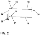
- exemplary embodiment of an internal combustion engine comprises a cylinder head 10, are integrated into the working cylinder, not shown, in each of which a reciprocating piston (not shown) oscillating between a top dead center (TDC) and bottom dead center (UT) moves.
- the cylinder head 10 includes an exhaust side 12, at which exhaust gases are discharged from the working cylinders, and an inlet side 14, at which the working cylinders fresh gas is supplied.
- Each working cylinder is associated with two intake valves (not shown) and two exhaust valves (not shown), with a fixed camshaft 16 and a variable camshaft 18 being provided.
- the fixed camshaft 16 carries intake cams 20, each actuating an intake valve, and exhaust cams 22, each actuating an exhaust valve.
- the variable camshaft 18 carries intake cams 24, each actuating an intake valve, and exhaust cams 26, each actuating an exhaust valve.
- intake cams 20, 24 and exhaust cams 22, 26 alternate as seen in the longitudinal direction. In this way, the two intake valves and exhaust valves of each working cylinder are actuated by different camshafts 16, 18.
- each of the camshafts 16, 18 is a so-called mixed camshaft, ie, each camshaft 16, 18 actuates both intake and exhaust valves via respective intake cams 20, 24 and exhaust cams 22, 26, respectively.
- the timing of the fixed camshaft 16 for the intake and exhaust valves associated therewith are fixed unchangeable.
- an adjuster 28 is arranged, via which the timing of the associated intake and exhaust valves can be changed by the second camshaft 18 is rotated by the adjuster 28.
- the fixed camshaft 16 is driven at 30 by a crankshaft, not shown, of the internal combustion engine.
- the fixed camshaft 16 in turn drives the variable camshaft 18 via gears 32.
- crankshaft angle (in ° CW) is plotted on the horizontal axis and a lifting movement (in mm) on the vertical axis.
- On the horizontal axis is at -180 ° KW, a bottom dead center (UT) of the reciprocating piston before the charge cycle, at 0 ° KW, a top dead center (TDC) of the reciprocating piston during the charge cycle and at 180 ° KW, a bottom dead center (UT) of the reciprocating after the charge change.
- a first graph 34 illustrates lift over crankshaft angle for those exhaust valves controlled by the exhaust cam 22 of the fixed camshaft 16.
- a second graph 36 (dashed) illustrates the lift over crankshaft angle for those exhaust valves controlled by the exhaust cams 26 of the variable camshaft 18.
- a third graph 38 illustrates lift over crankshaft angle for those intake valves controlled by intake cam 20 of fixed camshaft 16
- fourth graph 40 (dashed) illustrates lift over crankshaft angle for those intake valves coming in from intake lobes 24 of variable Camshaft 18 are controlled.
- Fig. 3 is shown a position of the variable camshaft with an adjustment angle of 0 ° KW, ie the camshafts 16, 18 are considered not rotated against each other.
- the exhaust valve actuated by the variable camshaft 18 opens at approximately -225 ° CA, which corresponds to 45 ° CA before the BDC of the piston.
- the corresponding exhaust valve of the fixed camshaft 16 opens at about -200 ° CA, which corresponds to 20 ° CA before UT of the piston.
- Fig. 4 is a position of the variable Nockenwelle18 shown with an adjustment angle of 10 °.
- the exhaust valve actuated by the variable camshaft 18 opens at a crankshaft angle of approximately -215 ° CA, which corresponds to 35 ° CA before UT of the piston.
- the stroke movement and thus the opening and closing shifts of the intake valve operated by the variable camshaft 18 is delayed by 10 ° with respect to the intake valve operated by the fixed camshaft 16.
- Fig. 5 is a position of the variable camshaft with an adjustment angle of about 40 °.
- the exhaust valve actuated by the variable camshaft 18 opens at a crankshaft angle of approximately -185 ° CA, which corresponds to 5 ° CA before UT of the piston.
- the stroke movement and thus the opening and closing of the intake valve operated by the variable camshaft 18 shifts 40 ° with respect to the intake valve operated by the fixed camshaft 16, late.
- the internal combustion engine in a known manner (see. DE 10 2006 042 912 A1 ) operated in a Miller cycle.
- An adjustment of the variable camshaft in an angular range of 0 ° to 5 ° is provided for a cold run of the internal combustion engine according to the invention.
- variable camshaft 18 An adjustment of the variable camshaft 18 in an angular range of 0 ° to 15 ° is provided for the full-load operation of the internal combustion engine according to the invention.
- variable camshaft 18 An adjustment of the variable camshaft 18 in an angular range of 15 ° to 50 ° is provided for operation of the internal combustion engine according to the invention with partial load.
- the expansion losses should be minimized
- the effective compression should be set at about 14 to 15 in order to reduce the emission behavior of the engine To optimize internal combustion engine.
- Fig. 6 is the course of the cylinder pressure (logarithmic, in bar) over the stroke volume (in cm 3 ) of a working cylinder of the internal combustion engine according to the invention for in the Fig. 4 and 5 illustrated adjustment positions of the variable camshaft 18 shown.
- the integral of the cylinder pressure over the stroke volume is a measure of the engine power. It can be seen that by the inventive design of the internal combustion engine with a relatively late opening of the actuated by the fixed camshaft 16 exhaust valve in conjunction with an adjustment of the actuated by the variable camshaft exhaust valve late, the engine power can be increased by 42 marked area. This increased engine power can be exploited in part-load operation for an increase in the efficiency of the internal combustion engine.
Description
Die Erfindung betrifft eine Brennkraftmaschine, insbesondere eine Dieselbrennkraftmaschine, insbesondere eines Kraftfahrzeugs, sowie ein Verfahren zum Betreiben einer solchen Brennkraftmaschine, mit mindestens einem Arbeitszylinder, dem wenigstens zwei Einlass- und zwei Auslassventile zugeordnet sind und in dem ein Hubkolben oszillierend zwischen einem oberen Totpunkt (OT) und einem unteren Totpunkt (UT) bewegt wird, wobei der Hubkolben abwechselnd mit einem Ladungswechselhub, der einen Ausstoßtakt sowie einen Ansaugtakt umfasst, und einem Arbeitshub, der einen Verdichtungstakt und einen Arbeitstakt umfasst, eine Kurbelwelle antreibt, wobei in Abhängigkeit von einem Kurbelwellenwinkel im Ladungswechselhub des Hubkolbens die Einlass- und Auslassventile geöffnet und geschlossen werden, wobei eine Verdichtung in dem Arbeitszylinder dadurch abgesenkt wird, dass nach einem UT am Ende des Ladungswechselhubes ein Schließzeitpunkt von zumindest einem Einlassventils soweit nach spät verschoben wird, dass ein Teil der zuvor im Ansaugtakt angesaugten Frischgasmenge durch dieses Einlassventil im Verdichtungstakt wieder ausgeschoben wird.The invention relates to an internal combustion engine, in particular a diesel internal combustion engine, in particular of a motor vehicle, and a method for operating such an internal combustion engine, with at least one working cylinder, the at least two inlet and two outlet valves are assigned and in which a reciprocating oscillating between a top dead center (OT ) and a bottom dead center (UT) is moved, wherein the reciprocating piston alternately with a charge cycle, which includes an exhaust stroke and an intake stroke, and a power stroke, which includes a compression stroke and a power stroke, a crankshaft, wherein a function of a crankshaft angle in Ladungswechselhub the reciprocating piston, the intake and exhaust valves are opened and closed, wherein a compression in the working cylinder is lowered by the fact that after a UT at the end of Ladungswechselhubes a closing time of at least one intake valve far late above is that a portion of the previously sucked in the intake stroke amount of fresh gas is pushed out through this inlet valve in the compression stroke again.
Beim bekannten Miller-Cycle wird der Zeitpunkt "Einlassventil schließt" (ES) nach spät verschoben. Auf diese Weise wird bereits im Zylinder befindliches Frischgas z.T. wieder in den Ansaugtrakt der Brennkraftmaschine ausgeschoben. Dies bedeutet einen Füllungsnachteil, der aber über eine Aufladung mit einem geeigneten Ladedruck kompensiert werden kann. Dabei wird beispielsweise der Ladedruck im Volumen zwischen dem Ausgang eines Turboladers und dem Einlass der Brennkraftmaschine so geregelt, dass der Ladedruck in jedem Miller-Betriebspunkt, d.h. jeder Betriebspunkt in dem der "Miller-Cycle" zur Anwendung kommt, dem theoretischen Verdichtungsenddruck in den Arbeitszylindern der Brennkraftmaschine zum Zeitpunkt Einlassventil schließt entspricht. Für die Regelung, wahlweise auch Steuerung, kommen Druck- und/oder Temperatur- und/oder Massenstromsensoren oder sinnvolle Kombisensoren der drei angesprochenen Sensortypen zum Einsatz.In the well-known Miller cycle, the time "intake valve closes" (ES) is postponed. In this way, already in-cylinder fresh gas is z.T. pushed back into the intake of the engine. This means a filling disadvantage, which can be compensated but via a charge with a suitable boost pressure. In this example, the boost pressure in the volume between the output of a turbocharger and the inlet of the internal combustion engine is controlled so that the boost pressure in each Miller operating point, i. each operating point in which the "Miller-cycle" is used, the theoretical compression end pressure in the working cylinders of the internal combustion engine at the time intake valve closes corresponds. For the control, optionally also control, come pressure and / or temperature and / or mass flow sensors or useful combination sensors of the three types of sensor used.
Der positive Effekt des Miller-Cycles mittels frühem oder spätem Zeitpunkt für das Schließen des Einlassventils auf die NOx-Emission und Homogenisierbarkeit des Dieselgemischs ist bekannt. Eine Dieselbrennkraftmaschine mit einer variablen Ventilsteuerung, die nach dem Miller-Cycle betrieben werden kann, ist aus der
Die
Ausgehend von diesem Stand der Technik lag der Erfindung die Aufgabe zugrunde, eine Brennkraftmaschine anzugeben, die sich durch einen höheren Wirkungsgrad auszeichnet.Based on this prior art, the present invention seeks to provide an internal combustion engine, which is characterized by a higher efficiency.
Diese Aufgabe wird erfindungsgemäß durch eine Brennkraftmaschine gemäß dem unabhängigen Patentanspruch 1 sowie durch ein Verfahren gemäß dem unabhängigen Patentanspruch 6 gelöst. Vorteilhafte Ausgestaltungen der Erfindung sind Gegenstand der jeweiligen abhängigen Patentansprüche und ergeben sich aus der nachfolgenden Beschreibung der Erfindung.This object is achieved by an internal combustion engine according to
Der Erfindung liegt der Gedanke zugrunde, bei einer Brennkraftmaschine gemäß der
Eine gattungsgemäße Brennkraftmaschine, die mindestens einen Arbeitszylinder mit einem zwischen einem oberen Totpunkt (OT) und einem unteren Totpunkt (UT) bewegbaren Kolben sowie jeweils mindestens zwei dem Arbeitszylinder zugeordnete Einlass- und zwei Auslassventile sowie mindestens zwei Nockenwellen aufweist, die als sogenannte gemischte Nockenwelle ausgebildet ist, d.h. diese Nockenwellen betätigen sowohl mindestens ein Auslass- und ein Einlassventil, wobei an einer der Nockenwellen, der variablen Nockenwelle, ein Versteller angeordnet ist, der die Ventilsteuerzeiten der entsprechenden Ein- und Auslassventile verstellt, ist demnach erfindungsgemäß dadurch weitergebildet, dass das Öffnen des von der festen Nockenwelle betätigten Auslassventils in einem Bereich zwischen 0°KW vor UT (unterem Totpunkt) und 25°KW vor UT, vorzugsweise in einem Bereich von 10°KW vor UT und 20°KW vor UT und besonders bevorzugt bei ca. 20°KW vor UT erfolgt. Durch dieses vergleichsweise späte Öffnen des von der festen Nockenwelle betätigten Auslassventils ergibt sich dessen erfindungsgemäß verkürzte Öffnungsdauer, da eine Verlagerung der Öffnungsdauer nach spät nicht in beliebigem Maße möglich ist, da es ansonsten zu einer Kollision des Ventils mit dem sich dann im OT befindlichen Kolben kommen würde.A generic internal combustion engine having at least one working cylinder with a movable between a top dead center (TDC) and a bottom dead center (UT) and each piston at least two the cylinder associated intake and two exhaust valves and at least two camshafts, designed as a so-called mixed camshaft is, ie these camshafts actuate both at least one exhaust and an intake valve, wherein on one of the camshaft, the variable camshaft, a phaser is arranged, which adjusts the valve timing of the respective intake and exhaust valves, is accordingly further developed according to the invention that the opening of the exhaust cam operated by the fixed camshaft in a range between 0 ° CA before UT (bottom dead center) and 25 ° CA before UT, preferably in a range of 10 ° CA before UT and 20 ° CA before UT and more preferably at about 20 ° KW before UT. By this comparatively late opening of the actuated by the fixed camshaft exhaust valve results in accordance with the invention shortened opening time, since a shift of the opening period is not possible to any extent late, otherwise there is a collision of the valve with the then located in the TDC piston would.
In einer bevorzugten Ausführungsform der erfindungsgemäßen Brennkraftmaschine ist der Versteller der variablen Nockenwelle derart ausgebildet, dass dieser einen Verstellbereich für die Ventilsteuerzeiten von ca. 50° ermöglicht.In a preferred embodiment of the internal combustion engine according to the invention, the phaser of the variable camshaft is designed such that it allows an adjustment range for the valve timing of about 50 °.
Vorzugsweise ist vorgesehen, dass in einer ersten Verstellposition der variablen Nockenwelle das von dieser Nockenwelle betätigte Auslassventil früher öffnet als das von der festen Nockenwelle betätigte Auslassventil, während das von der variablen Nockenwelle betätigte Einlassventil im Wesentlichen gleichzeitig mit dem von der festen Nockenwelle betätigten Einlassventil öffnet und schließt (d.h. übereinstimmende Öffnungsdauer). Diese erste Verstellposition kann durch einen Verstellwinkel von 0° definiert werden, bei dem die variable Nockenwelle als nicht gegenüber der festen Nockwelle verstellt (d.h. verdreht) angesehen werden kann. In dieser ersten Verstellposition mit einem Verstellwinkel von 0° kann das von der variablen Nockenwelle betätigte Auslassventil vorzugsweise bei ca. 45°KW vor UT öffnen.Preferably, in a first variable camshaft adjustment position, the exhaust valve actuated by this camshaft opens earlier than the fixed cam operated exhaust valve while the variable camshaft actuated intake valve opens substantially simultaneously with the intake cam operated intake valve closes (ie matching opening duration). This first adjustment position may be defined by an offset angle of 0 ° at which the variable camshaft may not be considered misaligned (i.e., rotated) with respect to the fixed camshaft. In this first adjustment position with an adjustment angle of 0 °, the exhaust valve actuated by the variable camshaft may preferably open at approximately 45 ° CA before BDC.
Ein Betrieb der Brennkraftmaschine in dieser ersten Verstellposition sowie in einem Bereich des Verstellwinkels von bis zu ca. 5° eignet sich vorzugsweise für einen Kaltlauf der Brennkraftmaschine, d.h. wenn diese noch nicht ihre Betriebstemperatur erreicht hat. Durch die Kombination aus einer übereinstimmenden Öffnungsdauer der Einlassventile der variablen und der festen Nockenwelle mit der definierten Überschneidung der Öffnungsdauer der von den Nockenwellen betätigten Auslassventile kann die Aufheizung eines der Brennkraftmaschine nachgeschalteten Katalysators positiv beeinflusst und eine maximale effektive Verdichtung erreicht werden, woraus ein Liefergradoptimum bei niedrigen Drehzahlen resultieren kann.An operation of the internal combustion engine in this first adjustment position and in a range of the adjustment angle of up to about 5 ° is preferably suitable for a cold run of the internal combustion engine, i. if it has not yet reached its operating temperature. The combination of a consistent opening duration of the intake valves of the variable and fixed camshaft with the defined overlap of the opening duration of the exhaust valves operated by the camshaft, the heating of a catalytic converter downstream of the catalyst can be positively influenced and a maximum effective compression can be achieved, resulting in a optimal delivery at low Speeds can result.
In einer bevorzugten Ausführungsform des erfindungsgemäßen Verfahrens kann weiterhin vorgesehen sein, die Brennkraftmaschine bei Volllast mit einem Verstellwinkel von ca. 0° bis ca. 15° zu betreiben, wodurch eine Liefergradsteigerung über einen fülligeren Hubverlauf erreicht werden kann. Zudem sinkt die effektive Verdichtung leicht, womit eine entsprechende Spitzendruckbegrenzung verbunden ist.In a preferred embodiment of the method according to the invention can also be provided to operate the engine at full load with an adjustment of about 0 ° to about 15 °, whereby a degree of delivery can be achieved over a fuller Hubverlauf. In addition, the effective compression decreases easily, which is associated with a corresponding peak pressure limit.
In einer weiterhin bevorzugten Ausführungsform des erfindungsgemäßen Verfahrens kann vorgesehen sein, die Brennkraftmaschine bei Teillast mit einem Verstellwinkel von ca. 15° bis ca. 50° zu betreiben, wodurch die Expansionsverluste reduziert und eine hinsichtlich der erzeugten Abgasemissionen vorteilhafte effektive Verdichtung in einem Bereich von 14 bis 15 erreicht werden kann.In a further preferred embodiment of the method according to the invention can be provided to operate the engine at part load with an adjustment of about 15 ° to about 50 °, thereby reducing the expansion losses and advantageous in terms of the exhaust emissions produced effective compression in a range of 14 to 15 can be achieved.
Die Erfindung wird nachfolgend anhand eines in den Zeichnungen dargestellten Ausführungsbeispiels näher erläutert. Diese zeigen in
- Fig. 1:
- eine beispielhafte Ausführungsform einer Brennkraftmaschine in schematischer Ansicht,
- Fig. 2:
- eine schematische Darstellung der Nockenwellenanordnung bei der Brennkraftmaschine gemäß
Fig. 1 , - Fig. 3:
- eine graphische Darstellung der Ventilbewegung der Einlass- und Auslassventile bei einem Verstellwinkel von 0°;
- Fig. 4:
- eine graphische Darstellung der Ventilbewegung der Einlass- und Auslassventile bei einem Verstellwinkel von 10°;
- Fig. 5:
- eine graphische Darstellung der Ventilbewegung der Einlass- und Auslassventile bei einem Verstellwinkel von 40°; und
- Fig. 6:
- ein p-V-Diagramm für die den
Fig. 4 und 5 entsprechenden Verstellpositionen der variablen Nockenwelle.
- Fig. 1:
- an exemplary embodiment of an internal combustion engine in a schematic view,
- Fig. 2:
- a schematic representation of the camshaft assembly in the internal combustion engine according to
Fig. 1 . - 3:
- a graphical representation of the valve movement of the intake and exhaust valves at an adjustment angle of 0 °;
- 4:
- a graphical representation of the valve movement of the intake and exhaust valves at an adjustment angle of 10 °;
- Fig. 5:
- a graphical representation of the valve movement of the intake and exhaust valves at an adjustment angle of 40 °; and
- Fig. 6:
- a pV diagram for the
4 and 5 corresponding adjustment positions of the variable camshaft.
Die in
Jedem Arbeitszylinder sind zwei Einlassventile (nicht dargestellt) und zwei Auslassventile (nicht dargestellt) zugeordnet, wobei eine feste Nockenwelle 16 und eine variable Nockenwelle 18 vorgesehen sind. Die feste Nockwelle 16 trägt Einlassnocken 20, die jeweils ein Einlassventil betätigen, und Auslassnocken 22, die jeweils ein Auslassventil betätigen. Ebenso trägt die variable Nockenwelle 18 Einlassnocken 24, die jeweils ein Einlassventil betätigen, und Auslassnocken 26, die jeweils ein Auslassventil betätigen. Auf beiden Nockenwellen 16, 18 wechseln sich in Längsrichtung gesehen jeweils Einlassnocken 20, 24 und Auslassnocken 22, 26 ab. Auf diese Weise werden die beiden Einlassventile und Auslassventile eines jeden Arbeitszylinders von verschiedenen Nockenwellen 16, 18 betätigt. Somit ist jede der Nockenwellen 16, 18 eine sogenannte gemischte Nockenwelle, d.h. jede Nockenwelle 16, 18 betätigt sowohl Einlass- als auch Auslassventile über entsprechende Einlassnocken 20, 24 bzw. Auslassnocken 22, 26.Each working cylinder is associated with two intake valves (not shown) and two exhaust valves (not shown), with a
Die Steuerzeiten der festen Nockenwelle 16 für die dieser zugeordneten Einlass- und Auslassventile sind unveränderbar festgelegt. An der variablen Nockenwelle 18 ist ein Versteller 28 angeordnet, über den die Steuerzeiten der dieser zugeordneten Einlass- und Auslassventile verändert werden können, indem die zweite Nockenwelle 18 durch den Versteller 28 verdreht wird. Die feste Nockenwelle 16 wird bei 30 von einer nicht dargestellten Kurbelwelle der Brennkraftmaschine angetrieben. Die feste Nockenwelle 16 treibt dann ihrerseits über Zahnräder 32 die variable Nockenwelle 18 an.The timing of the
In den
In
In
In der
Eine Verstellung der variablen Nockenwelle in einem Winkelbereich von 0° bis 5° ist für einen Kaltlauf der erfindungsgemäßen Brennkraftmaschine vorgesehen. Durch ein relativ frühes Öffnen des von der variablen Nockenwelle 18 betätigten Auslassventils soll das Aufheizen eines der Brennkraftmaschine nachgeschalteten (nicht dargestellten) Abgas-Katalysators sowie ein Hochlaufen eines (nicht dargestellten) Abgasturboladers unterstützt werden, wohingegen durch ein relativ frühes Schließen des von der variablen Nockenwelle 18 betätigten Einlassventils der Liefergrad bei niedrigen Drehzahlen der Brennkraftmaschine optimiert und eine maximale effektive Verdichtung erreicht werden soll.An adjustment of the variable camshaft in an angular range of 0 ° to 5 ° is provided for a cold run of the internal combustion engine according to the invention. By a relatively early opening of the actuated by the variable
Eine Verstellung der variablen Nockenwelle 18 in einem Winkelbereich von 0° bis 15° ist für den Volllast-Betrieb der erfindungsgemäßen Brennkraftmaschine vorgesehen. Durch ein in geringem Maße nach spät verstelltes Schließen des von der variablen Nockenwelle 18 betätigten Einlassventils soll bei einem weiterhin guten Liefergrad eine geringe Absenkung der effektiven Verdichtung mit dem Ziel der Spitzendruckbegrenzung erreicht werden. Dabei ist vorgesehen, die variable Nockenwelle 18 bei relativ niedrigen Drehzahlen in Richtung 5° Verstellwinkel und bei relativ hohen Drehzahlen in Richtung 15° Verstellwinkel zu verstellen.An adjustment of the
Eine Verstellung der variablen Nockenwelle 18 in einem Winkelbereich von 15° bis 50° ist für einem Betrieb der erfindungsgemäßen Brennkraftmaschine mit Teillast vorgesehen. Durch ein relativ spätes Öffnen des von der variablen Nockenwelle 18 betätigten Auslassventils sollen die Expansionsverluste minimiert werden, wohingegen durch ein relativ spätes Schließen des von der variablen Nockenwelle 18 betätigten Einlassventils die effektive Verdichtung bei ca. 14 bis 15 eingestellt werden soll, um das Emissionsverhalten der Brennkraftmaschine zu optimieren.An adjustment of the
In der
- 1010
- Zylinderkopfcylinder head
- 1212
- Auslassseiteoutlet
- 1414
- Einlassseiteinlet side
- 1616
- erste Nockenwellefirst camshaft
- 1818
- zweite Nockenwellesecond camshaft
- 2020
-
Einlassnocken der ersten Nockenwelle 16Intake cam of the
first camshaft 16 - 2222
-
Auslassnocken der ersten Nockenwelle 16Exhaust cam of the
first camshaft 16 - 2424
-
Einlassnocken der zweiten Nockenwelle 18Intake cam of the
second camshaft 18 - 2626
-
Auslassnocken der zweiten Nockenwelle 28Exhaust cams of the
second camshaft 28 - 2828
- Verstelleradjuster
- 3030
-
Antrieb erste Nockenwelle 16Drive
first camshaft 16 - 3232
- Zahnradgear
- 3434
- Graph: festes AuslassventilGraph: fixed exhaust valve
- 3636
- Graph: variables AuslassventilGraph: variable exhaust valve
- 3838
- Graph: festes EinlassventilGraph: fixed inlet valve
- 4040
- Graph: variables EinlassventilGraph: variable inlet valve
- 4242
- Fläche im p-V-DiagrammArea in the p-V diagram
Claims (8)
- An internal combustion engine with an operating cylinder, in which a piston is moved cyclically between an upper dead center (OT) and a lower dead center (UT), wherein two intake valves and two exhaust valves are assigned to the operating cylinder, and two cam shafts (16, 18), which in each case actuate an intake valve and an exhaust valve, wherein one cam shaft is designed as a variable cam shaft (18) with an adjuster (28) for adjusting the valve control times and the other cam shaft is designed as a fixed cam shaft with non-variable valve control times, characterized in that the opening of the exhaust valve actuated by the fixed cam shaft takes place in the range between 0° and 25° KW (crank angle) before the lower dead center of the piston.
- The internal combustion engine according to Claim 1, characterized in that the opening of the exhaust valve actuated by the fixed cam shaft takes place in a range of 10° to 20° KW before UT and preferably at approx. 20° KW before UT.
- The internal combustion engine according to Claim 1 or 2, characterized in that the adjuster (28) is designed in such a manner that said adjuster has an adjustment range of approx. 50°.
- The internal combustion engine according to any one of the preceding claims, characterized in that in a first adjustment position the exhaust valve actuated by the variable cam shaft (18) opens earlier than the exhaust valve actuated by the fixed cam shaft (16) and the intake valve actuated by the variable cam shaft (18) opens and closes simultaneously with the intake valve actuated by the fixed cam shaft (16).
- The internal combustion engine according to Claim 4, characterized in that the exhaust valve assigned to the variable cam shaft opens at approx. 45° KW before UT.
- A method for operating an internal combustion engine according to Claim 4 or 5, characterized in that said internal combustion engine is operated with an adjustment angle of 0° to approx. 5° in cold run.
- The method according to Claim 6, characterized in that the internal combustion engine is operated at full load with an adjustment angle of approx. 0° to approx. 15°.
- The method according to Claim 6 or 7, characterized in that the internal combustion engine is operated at partial load with an adjustment angle of approx. 15° to approx. 50°.
Applications Claiming Priority (1)
| Application Number | Priority Date | Filing Date | Title |
|---|---|---|---|
| DE102011103870A DE102011103870A1 (en) | 2011-06-10 | 2011-06-10 | Internal combustion engine |
Publications (3)
| Publication Number | Publication Date |
|---|---|
| EP2532860A2 EP2532860A2 (en) | 2012-12-12 |
| EP2532860A3 EP2532860A3 (en) | 2017-02-01 |
| EP2532860B1 true EP2532860B1 (en) | 2019-10-02 |
Family
ID=46146561
Family Applications (1)
| Application Number | Title | Priority Date | Filing Date |
|---|---|---|---|
| EP12003592.8A Active EP2532860B1 (en) | 2011-06-10 | 2012-05-08 | Combustion engine |
Country Status (2)
| Country | Link |
|---|---|
| EP (1) | EP2532860B1 (en) |
| DE (1) | DE102011103870A1 (en) |
Families Citing this family (1)
| Publication number | Priority date | Publication date | Assignee | Title |
|---|---|---|---|---|
| DE102012024318A1 (en) * | 2012-12-13 | 2014-06-18 | Volkswagen Aktiengesellschaft | Method for operating an internal combustion engine |
Family Cites Families (6)
| Publication number | Priority date | Publication date | Assignee | Title |
|---|---|---|---|---|
| DE10359058A1 (en) * | 2003-12-17 | 2005-07-21 | Daimlerchrysler Ag | Gas exchange valve device for internal combustion engine, has operating unit to cover cam shafts whose rotation angle is adjusted by adjusting device, and valves propelled over cam shafts that are coupled with actuators to operate valves |
| DE102006042912A1 (en) | 2006-09-13 | 2008-03-27 | Volkswagen Ag | Internal combustion engine with mixed camshafts |
| DE102007040697A1 (en) * | 2007-08-29 | 2009-03-05 | Volkswagen Ag | Internal combustion engine |
| DE102007046656B4 (en) * | 2007-09-28 | 2018-09-13 | Audi Ag | Method for operating an internal combustion engine, internal combustion engine |
| DE102007049109A1 (en) * | 2007-10-12 | 2009-04-16 | Volkswagen Ag | Internal combustion engine with mixed camshafts |
| DE102009024903A1 (en) * | 2009-06-15 | 2010-12-16 | Volkswagen Ag | Method for operating a reciprocating internal combustion engine |
-
2011
- 2011-06-10 DE DE102011103870A patent/DE102011103870A1/en not_active Withdrawn
-
2012
- 2012-05-08 EP EP12003592.8A patent/EP2532860B1/en active Active
Non-Patent Citations (1)
| Title |
|---|
| None * |
Also Published As
| Publication number | Publication date |
|---|---|
| EP2532860A2 (en) | 2012-12-12 |
| EP2532860A3 (en) | 2017-02-01 |
| DE102011103870A1 (en) | 2012-12-13 |
Similar Documents
| Publication | Publication Date | Title |
|---|---|---|
| EP2048331B1 (en) | Combustion engine with mixed camshafts | |
| EP2066874B1 (en) | Internal combustion engine with mixed camshafts | |
| EP3610147B1 (en) | Method for operating an internal combustion engine, and internal combustion engine | |
| WO2017211574A1 (en) | Method for operating an internal combustion engine, and internal combustion engine | |
| DE10359267B4 (en) | Internal combustion engine with intake valves, variable valve timing and timing | |
| DE112014000451T5 (en) | Control system for a gaseous fuel engine with cam phasing to improve engine start | |
| EP2726721B1 (en) | Internal combustion engine | |
| WO2013189698A1 (en) | Method for operating an internal combustion engine which is operated according to a self-ignition method, and internal combustion engine | |
| WO2009030694A2 (en) | Piston engine | |
| EP1331382B1 (en) | Method, computer programme, control and/or regulation device for operation of an internal combustion engine and internal combustion engine | |
| EP2264299A2 (en) | Method for operating a reciprocating piston combustion engine | |
| DE102014208950A1 (en) | Internal combustion engine and method for operating such an internal combustion engine | |
| EP2500533A2 (en) | Combustion engine with mixed cam shaft | |
| EP1306527B1 (en) | Diesel engine with variable compression ratio | |
| EP2532860B1 (en) | Combustion engine | |
| EP2976512B1 (en) | Internal combustion engine and method of operating this internal conmbustion engine | |
| DE102016200487A1 (en) | Internal combustion engine | |
| WO2016016228A1 (en) | Internal combustion engine having an adjustable compression ratio and a connecting cam and method for operating such an internal combustion engine | |
| WO2013110429A1 (en) | Internal combustion engine valve train device | |
| DE102010051832B4 (en) | Method for operating a reciprocating internal combustion engine with a swirl combustion process | |
| DE102015110558A1 (en) | Internal combustion engine and method for operating such an internal combustion engine | |
| DE102012206683B4 (en) | Valve drive for a cylinder head of an internal combustion engine | |
| EP3728818B1 (en) | Method for operating a combustion engine, and combustion engine | |
| DE102007041326A1 (en) | Method for operating internal combustion engine, particularly diesel engine, particularly of motor vehicle, involves introducing combustion air through two inlet channels in working cylinder of internal combustion engine | |
| DE102007047566A1 (en) | Internal-combustion engine operating method, involves varying closing flank such that energy conversion value is reached and adjusting flank into middle region between early and late time at relatively early time |
Legal Events
| Date | Code | Title | Description |
|---|---|---|---|
| PUAI | Public reference made under article 153(3) epc to a published international application that has entered the european phase |
Free format text: ORIGINAL CODE: 0009012 |
|
| AK | Designated contracting states |
Kind code of ref document: A2 Designated state(s): AL AT BE BG CH CY CZ DE DK EE ES FI FR GB GR HR HU IE IS IT LI LT LU LV MC MK MT NL NO PL PT RO RS SE SI SK SM TR |
|
| AX | Request for extension of the european patent |
Extension state: BA ME |
|
| PUAL | Search report despatched |
Free format text: ORIGINAL CODE: 0009013 |
|
| AK | Designated contracting states |
Kind code of ref document: A3 Designated state(s): AL AT BE BG CH CY CZ DE DK EE ES FI FR GB GR HR HU IE IS IT LI LT LU LV MC MK MT NL NO PL PT RO RS SE SI SK SM TR |
|
| AX | Request for extension of the european patent |
Extension state: BA ME |
|
| RIC1 | Information provided on ipc code assigned before grant |
Ipc: F02D 13/02 20060101AFI20161223BHEP |
|
| STAA | Information on the status of an ep patent application or granted ep patent |
Free format text: STATUS: REQUEST FOR EXAMINATION WAS MADE |
|
| 17P | Request for examination filed |
Effective date: 20170801 |
|
| RBV | Designated contracting states (corrected) |
Designated state(s): AL AT BE BG CH CY CZ DE DK EE ES FI FR GB GR HR HU IE IS IT LI LT LU LV MC MK MT NL NO PL PT RO RS SE SI SK SM TR |
|
| STAA | Information on the status of an ep patent application or granted ep patent |
Free format text: STATUS: EXAMINATION IS IN PROGRESS |
|
| 17Q | First examination report despatched |
Effective date: 20190104 |
|
| GRAP | Despatch of communication of intention to grant a patent |
Free format text: ORIGINAL CODE: EPIDOSNIGR1 |
|
| STAA | Information on the status of an ep patent application or granted ep patent |
Free format text: STATUS: GRANT OF PATENT IS INTENDED |
|
| INTG | Intention to grant announced |
Effective date: 20190520 |
|
| GRAS | Grant fee paid |
Free format text: ORIGINAL CODE: EPIDOSNIGR3 |
|
| GRAA | (expected) grant |
Free format text: ORIGINAL CODE: 0009210 |
|
| STAA | Information on the status of an ep patent application or granted ep patent |
Free format text: STATUS: THE PATENT HAS BEEN GRANTED |
|
| AK | Designated contracting states |
Kind code of ref document: B1 Designated state(s): AL AT BE BG CH CY CZ DE DK EE ES FI FR GB GR HR HU IE IS IT LI LT LU LV MC MK MT NL NO PL PT RO RS SE SI SK SM TR |
|
| REG | Reference to a national code |
Ref country code: GB Ref legal event code: FG4D Free format text: NOT ENGLISH |
|
| REG | Reference to a national code |
Ref country code: CH Ref legal event code: EP Ref country code: AT Ref legal event code: REF Ref document number: 1186423 Country of ref document: AT Kind code of ref document: T Effective date: 20191015 |
|
| REG | Reference to a national code |
Ref country code: DE Ref legal event code: R096 Ref document number: 502012015334 Country of ref document: DE |
|
| REG | Reference to a national code |
Ref country code: IE Ref legal event code: FG4D Free format text: LANGUAGE OF EP DOCUMENT: GERMAN |
|
| REG | Reference to a national code |
Ref country code: NL Ref legal event code: MP Effective date: 20191002 |
|
| REG | Reference to a national code |
Ref country code: LT Ref legal event code: MG4D |
|
| PG25 | Lapsed in a contracting state [announced via postgrant information from national office to epo] |
Ref country code: GR Free format text: LAPSE BECAUSE OF FAILURE TO SUBMIT A TRANSLATION OF THE DESCRIPTION OR TO PAY THE FEE WITHIN THE PRESCRIBED TIME-LIMIT Effective date: 20200103 Ref country code: PL Free format text: LAPSE BECAUSE OF FAILURE TO SUBMIT A TRANSLATION OF THE DESCRIPTION OR TO PAY THE FEE WITHIN THE PRESCRIBED TIME-LIMIT Effective date: 20191002 Ref country code: NO Free format text: LAPSE BECAUSE OF FAILURE TO SUBMIT A TRANSLATION OF THE DESCRIPTION OR TO PAY THE FEE WITHIN THE PRESCRIBED TIME-LIMIT Effective date: 20200102 Ref country code: SE Free format text: LAPSE BECAUSE OF FAILURE TO SUBMIT A TRANSLATION OF THE DESCRIPTION OR TO PAY THE FEE WITHIN THE PRESCRIBED TIME-LIMIT Effective date: 20191002 Ref country code: LV Free format text: LAPSE BECAUSE OF FAILURE TO SUBMIT A TRANSLATION OF THE DESCRIPTION OR TO PAY THE FEE WITHIN THE PRESCRIBED TIME-LIMIT Effective date: 20191002 Ref country code: PT Free format text: LAPSE BECAUSE OF FAILURE TO SUBMIT A TRANSLATION OF THE DESCRIPTION OR TO PAY THE FEE WITHIN THE PRESCRIBED TIME-LIMIT Effective date: 20200203 Ref country code: FI Free format text: LAPSE BECAUSE OF FAILURE TO SUBMIT A TRANSLATION OF THE DESCRIPTION OR TO PAY THE FEE WITHIN THE PRESCRIBED TIME-LIMIT Effective date: 20191002 Ref country code: BG Free format text: LAPSE BECAUSE OF FAILURE TO SUBMIT A TRANSLATION OF THE DESCRIPTION OR TO PAY THE FEE WITHIN THE PRESCRIBED TIME-LIMIT Effective date: 20200102 Ref country code: NL Free format text: LAPSE BECAUSE OF FAILURE TO SUBMIT A TRANSLATION OF THE DESCRIPTION OR TO PAY THE FEE WITHIN THE PRESCRIBED TIME-LIMIT Effective date: 20191002 Ref country code: LT Free format text: LAPSE BECAUSE OF FAILURE TO SUBMIT A TRANSLATION OF THE DESCRIPTION OR TO PAY THE FEE WITHIN THE PRESCRIBED TIME-LIMIT Effective date: 20191002 Ref country code: ES Free format text: LAPSE BECAUSE OF FAILURE TO SUBMIT A TRANSLATION OF THE DESCRIPTION OR TO PAY THE FEE WITHIN THE PRESCRIBED TIME-LIMIT Effective date: 20191002 |
|
| PG25 | Lapsed in a contracting state [announced via postgrant information from national office to epo] |
Ref country code: IS Free format text: LAPSE BECAUSE OF FAILURE TO SUBMIT A TRANSLATION OF THE DESCRIPTION OR TO PAY THE FEE WITHIN THE PRESCRIBED TIME-LIMIT Effective date: 20200224 Ref country code: CZ Free format text: LAPSE BECAUSE OF FAILURE TO SUBMIT A TRANSLATION OF THE DESCRIPTION OR TO PAY THE FEE WITHIN THE PRESCRIBED TIME-LIMIT Effective date: 20191002 Ref country code: HR Free format text: LAPSE BECAUSE OF FAILURE TO SUBMIT A TRANSLATION OF THE DESCRIPTION OR TO PAY THE FEE WITHIN THE PRESCRIBED TIME-LIMIT Effective date: 20191002 Ref country code: RS Free format text: LAPSE BECAUSE OF FAILURE TO SUBMIT A TRANSLATION OF THE DESCRIPTION OR TO PAY THE FEE WITHIN THE PRESCRIBED TIME-LIMIT Effective date: 20191002 |
|
| PG25 | Lapsed in a contracting state [announced via postgrant information from national office to epo] |
Ref country code: AL Free format text: LAPSE BECAUSE OF FAILURE TO SUBMIT A TRANSLATION OF THE DESCRIPTION OR TO PAY THE FEE WITHIN THE PRESCRIBED TIME-LIMIT Effective date: 20191002 |
|
| REG | Reference to a national code |
Ref country code: DE Ref legal event code: R097 Ref document number: 502012015334 Country of ref document: DE |
|
| PG2D | Information on lapse in contracting state deleted |
Ref country code: IS |
|
| PG25 | Lapsed in a contracting state [announced via postgrant information from national office to epo] |
Ref country code: DK Free format text: LAPSE BECAUSE OF FAILURE TO SUBMIT A TRANSLATION OF THE DESCRIPTION OR TO PAY THE FEE WITHIN THE PRESCRIBED TIME-LIMIT Effective date: 20191002 Ref country code: EE Free format text: LAPSE BECAUSE OF FAILURE TO SUBMIT A TRANSLATION OF THE DESCRIPTION OR TO PAY THE FEE WITHIN THE PRESCRIBED TIME-LIMIT Effective date: 20191002 Ref country code: RO Free format text: LAPSE BECAUSE OF FAILURE TO SUBMIT A TRANSLATION OF THE DESCRIPTION OR TO PAY THE FEE WITHIN THE PRESCRIBED TIME-LIMIT Effective date: 20191002 Ref country code: IS Free format text: LAPSE BECAUSE OF FAILURE TO SUBMIT A TRANSLATION OF THE DESCRIPTION OR TO PAY THE FEE WITHIN THE PRESCRIBED TIME-LIMIT Effective date: 20200202 |
|
| PLBE | No opposition filed within time limit |
Free format text: ORIGINAL CODE: 0009261 |
|
| STAA | Information on the status of an ep patent application or granted ep patent |
Free format text: STATUS: NO OPPOSITION FILED WITHIN TIME LIMIT |
|
| PG25 | Lapsed in a contracting state [announced via postgrant information from national office to epo] |
Ref country code: SM Free format text: LAPSE BECAUSE OF FAILURE TO SUBMIT A TRANSLATION OF THE DESCRIPTION OR TO PAY THE FEE WITHIN THE PRESCRIBED TIME-LIMIT Effective date: 20191002 Ref country code: IT Free format text: LAPSE BECAUSE OF FAILURE TO SUBMIT A TRANSLATION OF THE DESCRIPTION OR TO PAY THE FEE WITHIN THE PRESCRIBED TIME-LIMIT Effective date: 20191002 Ref country code: SK Free format text: LAPSE BECAUSE OF FAILURE TO SUBMIT A TRANSLATION OF THE DESCRIPTION OR TO PAY THE FEE WITHIN THE PRESCRIBED TIME-LIMIT Effective date: 20191002 |
|
| 26N | No opposition filed |
Effective date: 20200703 |
|
| PG25 | Lapsed in a contracting state [announced via postgrant information from national office to epo] |
Ref country code: SI Free format text: LAPSE BECAUSE OF FAILURE TO SUBMIT A TRANSLATION OF THE DESCRIPTION OR TO PAY THE FEE WITHIN THE PRESCRIBED TIME-LIMIT Effective date: 20191002 |
|
| PG25 | Lapsed in a contracting state [announced via postgrant information from national office to epo] |
Ref country code: LI Free format text: LAPSE BECAUSE OF NON-PAYMENT OF DUE FEES Effective date: 20200531 Ref country code: CH Free format text: LAPSE BECAUSE OF NON-PAYMENT OF DUE FEES Effective date: 20200531 Ref country code: MC Free format text: LAPSE BECAUSE OF FAILURE TO SUBMIT A TRANSLATION OF THE DESCRIPTION OR TO PAY THE FEE WITHIN THE PRESCRIBED TIME-LIMIT Effective date: 20191002 |
|
| REG | Reference to a national code |
Ref country code: BE Ref legal event code: MM Effective date: 20200531 |
|
| GBPC | Gb: european patent ceased through non-payment of renewal fee |
Effective date: 20200508 |
|
| PG25 | Lapsed in a contracting state [announced via postgrant information from national office to epo] |
Ref country code: LU Free format text: LAPSE BECAUSE OF NON-PAYMENT OF DUE FEES Effective date: 20200508 |
|
| PG25 | Lapsed in a contracting state [announced via postgrant information from national office to epo] |
Ref country code: IE Free format text: LAPSE BECAUSE OF NON-PAYMENT OF DUE FEES Effective date: 20200508 Ref country code: FR Free format text: LAPSE BECAUSE OF NON-PAYMENT OF DUE FEES Effective date: 20200531 Ref country code: GB Free format text: LAPSE BECAUSE OF NON-PAYMENT OF DUE FEES Effective date: 20200508 |
|
| PG25 | Lapsed in a contracting state [announced via postgrant information from national office to epo] |
Ref country code: BE Free format text: LAPSE BECAUSE OF NON-PAYMENT OF DUE FEES Effective date: 20200531 |
|
| REG | Reference to a national code |
Ref country code: AT Ref legal event code: MM01 Ref document number: 1186423 Country of ref document: AT Kind code of ref document: T Effective date: 20200508 |
|
| PG25 | Lapsed in a contracting state [announced via postgrant information from national office to epo] |
Ref country code: AT Free format text: LAPSE BECAUSE OF NON-PAYMENT OF DUE FEES Effective date: 20200508 |
|
| PG25 | Lapsed in a contracting state [announced via postgrant information from national office to epo] |
Ref country code: TR Free format text: LAPSE BECAUSE OF FAILURE TO SUBMIT A TRANSLATION OF THE DESCRIPTION OR TO PAY THE FEE WITHIN THE PRESCRIBED TIME-LIMIT Effective date: 20191002 Ref country code: MT Free format text: LAPSE BECAUSE OF FAILURE TO SUBMIT A TRANSLATION OF THE DESCRIPTION OR TO PAY THE FEE WITHIN THE PRESCRIBED TIME-LIMIT Effective date: 20191002 Ref country code: CY Free format text: LAPSE BECAUSE OF FAILURE TO SUBMIT A TRANSLATION OF THE DESCRIPTION OR TO PAY THE FEE WITHIN THE PRESCRIBED TIME-LIMIT Effective date: 20191002 |
|
| PG25 | Lapsed in a contracting state [announced via postgrant information from national office to epo] |
Ref country code: MK Free format text: LAPSE BECAUSE OF FAILURE TO SUBMIT A TRANSLATION OF THE DESCRIPTION OR TO PAY THE FEE WITHIN THE PRESCRIBED TIME-LIMIT Effective date: 20191002 |
|
| PGFP | Annual fee paid to national office [announced via postgrant information from national office to epo] |
Ref country code: DE Payment date: 20220531 Year of fee payment: 11 |
|
| REG | Reference to a national code |
Ref country code: DE Ref legal event code: R119 Ref document number: 502012015334 Country of ref document: DE |