EP2500199A2 - Integrierter Elektromotor mit Geschwindigkeitssensor, Planetengetriebe und Lenkmittel - Google Patents
Integrierter Elektromotor mit Geschwindigkeitssensor, Planetengetriebe und Lenkmittel Download PDFInfo
- Publication number
- EP2500199A2 EP2500199A2 EP11164656A EP11164656A EP2500199A2 EP 2500199 A2 EP2500199 A2 EP 2500199A2 EP 11164656 A EP11164656 A EP 11164656A EP 11164656 A EP11164656 A EP 11164656A EP 2500199 A2 EP2500199 A2 EP 2500199A2
- Authority
- EP
- European Patent Office
- Prior art keywords
- output
- sun gear
- bearings
- interior
- output shaft
- Prior art date
- Legal status (The legal status is an assumption and is not a legal conclusion. Google has not performed a legal analysis and makes no representation as to the accuracy of the status listed.)
- Withdrawn
Links
Images


Classifications
-
- B—PERFORMING OPERATIONS; TRANSPORTING
- B60—VEHICLES IN GENERAL
- B60K—ARRANGEMENT OR MOUNTING OF PROPULSION UNITS OR OF TRANSMISSIONS IN VEHICLES; ARRANGEMENT OR MOUNTING OF PLURAL DIVERSE PRIME-MOVERS IN VEHICLES; AUXILIARY DRIVES FOR VEHICLES; INSTRUMENTATION OR DASHBOARDS FOR VEHICLES; ARRANGEMENTS IN CONNECTION WITH COOLING, AIR INTAKE, GAS EXHAUST OR FUEL SUPPLY OF PROPULSION UNITS IN VEHICLES
- B60K7/00—Disposition of motor in, or adjacent to, traction wheel
- B60K7/0007—Disposition of motor in, or adjacent to, traction wheel the motor being electric
-
- B—PERFORMING OPERATIONS; TRANSPORTING
- B60—VEHICLES IN GENERAL
- B60K—ARRANGEMENT OR MOUNTING OF PROPULSION UNITS OR OF TRANSMISSIONS IN VEHICLES; ARRANGEMENT OR MOUNTING OF PLURAL DIVERSE PRIME-MOVERS IN VEHICLES; AUXILIARY DRIVES FOR VEHICLES; INSTRUMENTATION OR DASHBOARDS FOR VEHICLES; ARRANGEMENTS IN CONNECTION WITH COOLING, AIR INTAKE, GAS EXHAUST OR FUEL SUPPLY OF PROPULSION UNITS IN VEHICLES
- B60K17/00—Arrangement or mounting of transmissions in vehicles
- B60K17/04—Arrangement or mounting of transmissions in vehicles characterised by arrangement, location or kind of gearing
- B60K17/043—Transmission unit disposed in on near the vehicle wheel, or between the differential gear unit and the wheel
- B60K17/046—Transmission unit disposed in on near the vehicle wheel, or between the differential gear unit and the wheel with planetary gearing having orbital motion
-
- B—PERFORMING OPERATIONS; TRANSPORTING
- B60—VEHICLES IN GENERAL
- B60K—ARRANGEMENT OR MOUNTING OF PROPULSION UNITS OR OF TRANSMISSIONS IN VEHICLES; ARRANGEMENT OR MOUNTING OF PLURAL DIVERSE PRIME-MOVERS IN VEHICLES; AUXILIARY DRIVES FOR VEHICLES; INSTRUMENTATION OR DASHBOARDS FOR VEHICLES; ARRANGEMENTS IN CONNECTION WITH COOLING, AIR INTAKE, GAS EXHAUST OR FUEL SUPPLY OF PROPULSION UNITS IN VEHICLES
- B60K17/00—Arrangement or mounting of transmissions in vehicles
- B60K17/04—Arrangement or mounting of transmissions in vehicles characterised by arrangement, location or kind of gearing
- B60K17/14—Arrangement or mounting of transmissions in vehicles characterised by arrangement, location or kind of gearing the motor of fluid or electric gearing being disposed in, or adjacent to, traction wheel
- B60K17/145—Arrangement or mounting of transmissions in vehicles characterised by arrangement, location or kind of gearing the motor of fluid or electric gearing being disposed in, or adjacent to, traction wheel the electric gearing being disposed in or adjacent to traction wheel
-
- B—PERFORMING OPERATIONS; TRANSPORTING
- B60—VEHICLES IN GENERAL
- B60K—ARRANGEMENT OR MOUNTING OF PROPULSION UNITS OR OF TRANSMISSIONS IN VEHICLES; ARRANGEMENT OR MOUNTING OF PLURAL DIVERSE PRIME-MOVERS IN VEHICLES; AUXILIARY DRIVES FOR VEHICLES; INSTRUMENTATION OR DASHBOARDS FOR VEHICLES; ARRANGEMENTS IN CONNECTION WITH COOLING, AIR INTAKE, GAS EXHAUST OR FUEL SUPPLY OF PROPULSION UNITS IN VEHICLES
- B60K17/00—Arrangement or mounting of transmissions in vehicles
- B60K17/30—Arrangement or mounting of transmissions in vehicles the ultimate propulsive elements, e.g. ground wheels, being steerable
-
- B—PERFORMING OPERATIONS; TRANSPORTING
- B60—VEHICLES IN GENERAL
- B60K—ARRANGEMENT OR MOUNTING OF PROPULSION UNITS OR OF TRANSMISSIONS IN VEHICLES; ARRANGEMENT OR MOUNTING OF PLURAL DIVERSE PRIME-MOVERS IN VEHICLES; AUXILIARY DRIVES FOR VEHICLES; INSTRUMENTATION OR DASHBOARDS FOR VEHICLES; ARRANGEMENTS IN CONNECTION WITH COOLING, AIR INTAKE, GAS EXHAUST OR FUEL SUPPLY OF PROPULSION UNITS IN VEHICLES
- B60K7/00—Disposition of motor in, or adjacent to, traction wheel
- B60K2007/0092—Disposition of motor in, or adjacent to, traction wheel the motor axle being coaxial to the wheel axle
Definitions
- the invention relates generally to electrical wheel motor drive systems for small compact construction equipment.
- FIGS. 1-3 are substantial duplicates from U.S. Patent Number 6,852,061 .
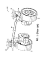
- Fig. 1 is a perspective view 100 of a pair of wheel motors in accordance with the prior art interconnected by a tie bar used for steering.
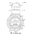
- Fig. 2 is a front view 200 of a wheel motor in accordance with the prior art.
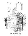
- Fig. 3 is a side, partially cross-sectional view 300 taken along line 3-3 of Fig. 2 in accordance with the prior art.
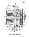
- Fig. 3A is a side, partially cross-sectional view 300A, of another embodiment of the prior art.
- wheel motor assembly 10 comprises spindle bracket 14 to which is mounted motor 18.
- the upper end 15 of spindle bracket 14 has a hollow cylindrical opening 20 formed throughout which is dimensional (sic, dimensioned) to receive the cylindrical shaft (not shown) mounted on bracket 16 so that the spindle bracket 14 can pivot about vertical axis 22.
- Motor 18 Electrical power is supplied to motor 18 through electrical cable 24 which is connected to an appropriate power source.
- the application of electrical power through cable 24 causes output shaft 26 or motor 18 to rotate.
- Output shaft 26 is supported for rotation by shaft bearing 28 positioned within a circular opening 29 through the lower end 57 of spindle bracket 14.
- An O-ring seal 30 is provided around the edge of motor 18 to prevent dust and debris from entering the motor compartment and to support the motor 18.
- a shaft lip seal 32 is provided to further seal the shaft 26 to prevent lubricant from exiting and dust and debris from entering the gear compartment 31.
- Gear compartment 31 comprises a hollow interior portion of the lower end 57 of spindle bracket 14.
- Shaft bearing 28 is retained in position by a retaining ring 34.
- Sun gear 36 is mounted on the end of output shaft 26 by a retaining ring 38 which engages a recess on the end of shaft 26.
- Sun gear 36 comprises a plurality of gear teeth which engage corresponding gear teeth on input planet gears 40 (only one of three shown).
- a ring gear 42 having a plurality of gear teeth is positioned to engage the teeth of input planet gears 40 so that rotation of the input sun gear 36 causes the input planet gears 40 to rotate within ring gear 42 to cause the input planet gears to circle around sun gear 36.
- Planet gears 40 are mounted for rotation on input planet pins 44 by lock ring 41, and are supported for rotation about input planet pins 44 by needle bearings 43.
- Pins 44 are mounted to an input carrier 46 which is joined to output sun gear 48.
- Input carrier 46 is locked to output sun gear 48 by a locking ring 49.
- Sun gear 48 is mounted for rotation around shaft 26.
- Output sun gear 48 has teeth which engage gear teeth on output planet gears 50 which are mounted for rotation to the spindle bracket 14 by output planet pins 52.
- Thrust washers 54 are provided on each side of output planet gears 50 around pin 52 and needle bearings 56 support the output planet gears 50 for easy rotation.
- hub 58 Mounted for rotation about lower end 57 of spindle bracket 14 is generally cylindrically shaped hub 58. Hub 58 is supported for rotation by bearings 60 and 62. Bearings 60 are retained in position by retaining ring 61. Joined to the interior surface 59 of hub 50 is an output ring gear 64 which engages output planet gears 50. Rotation of the output planet gears 50 caused by the rotation of the output sun gear 48 causes the output ring gear 64 to rotate causing joined hub 58 to rotate.
- the application of electrical power to motor 18 causes output shaft 26 and attached input sun gear 36 to rotate which in turn causes input planet gears to rotate around the interior of ring gear 42 which in turn rotates input carrier 46 and attached output sun gear 48 about shaft 26.
- output sun gear 48 causes output planet gears 50 to rotate which in turn causes output ring gear 64 and integrally joined hub 58 to rotate.
- a rubber wheel (not shown) is normally attached to the exterior surface 55 of hub 58 by bolts (not shown) screwed into threaded recesses 66 formed on a vertical face 68 of hub 58.
- a cover 70 overlies the open exterior end of hub 58 and is retained in position by a locking ring 72 which engages a groove at the open exterior end of hub 58.
- An O-ring seal 74 is positioned around the edge of cover 70 to prevent lubricant from exiting and dust and construction debris from entering the planetary gear compartment 31.
- a lip seal 76 is provided around the interior edge of hub 58 and the edge of spindle bracket 14 to prevent lubricant from exiting and dust and construction debris from entering the interior of the mechanism from the back side.
- Electric motor 18 has a braking mechanism 79 contained at the exterior end of motor 18 and is covered by cover 78.
- the braking mechanism operates to lock shaft 26 to prevent rotation of shaft 26 when electrical power is removed from motor 18 but to release shaft 26 for rotation whenever electrical power is applied to motor 18.
- This locking mechanism prevents movement of the wheels any time electrical power is not being applied.
- the assembly includes first and second steerable wheel motor assemblies for moving construction lifts and scaffold equipment.
- Each of the first and second steerable wheel motor assemblies for moving construction lifts and scaffold equipment includes a spindle bracket configured to be pivotably mounted at an upper end to a steering mechanism for rotation about a vertical axis.
- Each of the assemblies further includes an electric motor mounted to a lower end of the spindle bracket.
- the motor has an output shaft that rotates about an axis when electrical power is supplied to the motor.
- the output shaft is positioned through a shaft opening into an interior portion of the lower end of the spindle bracket.
- the output shaft is supported by a first set of bearings and a second set of bearings.
- the first set of bearings resides within the electric motor and the second set of bearings resides between the spindle bracket and the output shaft.
- the second set of bearings includes a speed and direction sensor integral therewith for detecting the speed and direction of rotation of the output shaft.
- the second set of bearings includes an inner race and an outer race.
- the inner race is affixed to the output shaft and rotatable therewith and the outer race is stationary.
- a magnetized impulse ring is affixed to the inner race and is rotatable therewith.
- a sensor body is affixed to the outer race of the second set of bearings which detects the magnetic impulses provided when the inner impulse ring and the shaft are rotating.
- a substantially cylindrical wheel hub is mounted to the spindle bracket for rotation about a horizontal axis coincident with the axis of rotation of the output shaft.
- the wheel hub includes an exterior surface to which a wheel can be mounted, an interior surface surrounding the interior portion of the lower end of the spindle bracket, an interior edge between the exterior and interior surfaces, and, an exterior edge between the exterior and interior surfaces.
- the hub is supported for rotation by a third set of bearings positioned adjacent the interior edge of the hub, and a fourth set of bearings positioned inwardly from the exterior edge of the hub.
- a multi-stage planetary gear system is mounted around the output shaft of the motor and positioned within the interior portion of the spindle bracket and within the cylindrical wheel hub between the exterior edge and the interior edge.
- the planetary gear system includes an input sun gear positioned between the fourth set of bearings and the exterior edge of the hub and mounted on the output shaft of the motor.
- the input sun gear includes a proximate portion and a distal portion.
- the planetary gear system further includes input planetary gears, a first ring gear affixed to the interior portion of the wheel hub, an input gear carrier including a splined interior, and, an output sun gear including a splined exterior.
- the output sun gear includes a proximate portion and a distal portion.
- a thrust washer resides between the spindle bracket and the proximate end of the output sun gear. The proximate portion of the output sun gear interengages the thrust washer and the distal portion of the output sun gear interengages the proximate portion of the input sun gear.
- An end cover is affixed to the wheel hub and is rotatable therewith.
- the end cover of the wheel hub includes a centrally located cylindrical recess therein.
- a circumferential spacer ring and a circumferential bracket reside in the cylindrical recess in the cover.
- the distal portion of the input sun gear interengages the circumferential bracket in the cylindrical recess in the cover.
- the input sun gear rotationally drives the input planetary gears which are in engagement with and react against the first ring gear producing rotation of the input gear carrier.
- the splined interior of the input gear carrier interengages the splined exterior of the output sun gear.
- the planetary gear system further includes output planetary gears driven by the splined exterior of the output sun gear.
- the output planetary gears are mounted for rotation with respect to the spindle.
- An output ring gear is positioned between the third set of bearings and the fourth set of bearings and joined to the interior surface of the wheel hub.
- the output ring gear engages the output planetary gears of the multistage planetary gear system so that rotation of the output planetary gears causes the output planetary gears and the wheel hub to rotate such that mechanical force through the planetary gear system is applied to the wheel hub.
- the speed and direction sensor which is integral with the second set of bearing unit outputs two square wave signals.
- a signal processor adapts the square wave signals for input into the microprocessor.
- the microprocessor receives the adapted square wave signals.
- An operator input station applies the desired wheel hub speed and direction to the microprocessor.
- the microprocessor receives the adapted square wave signals and compares the square wave signals to the desired wheel hub speed and direction input signals and outputs a corrective control signal according to an algorithm. Any number of algorithms may be used and the algorithms may be used to protect the motor.
- the microprocessor sometimes referred to herein as an embedded microcontroller or embedded microprocessor, protects the motors.
- a motor controller receives and processes the corrective control signal from the microprocessor and outputs a control signal to the electric motor dictating the speed and direction of the output shaft.
- Speed sensors can be used in a variety of different control scenarios some of which would be application dependent. Speed sensors may be used for traction control or to ensure that braking or acceleration is done at specific rate or within a specific distance. Speed sensors may also be used as an odometer and/or speedometer.
- a thrust washer between the spindle and the output sun gear allows control of the output sun gear and input carrier end play more precisely.
- Use of the thrust washer controls the end play of the output sun gear without requiring precise machining of the shaft within the motor and thus reduces cost and complexity in the electric motor.
- Use of the thrust washer enables proper fitting of the output sun gear within the required space. Without the use of the thrust washer, due to manufacturing tolerance buildup, the output sun gear may either be too loose or it may be too tight.
- the interengagement of the proximate portion of the output sun gear with the thrust washer, the interengagement of the distal portion of the output sun gear with the proximate portion of the first sun gear, and the interengagement of the distal portion of the input sun gear with the circumferential bracket in the cylindrical recess in the cover controls the position of the output sun gear axially.
- shoulder on output shaft must reside at the precise location distally with respect to the motor or another location on the output shaft. Put another way, shoulder on shaft must be located precisely with respect to spindle.
- the location of shoulder is important as a corresponding shoulder engages shoulder of output shaft and rotates with respect to output shaft .
- the precise location of shoulder on shaft determines whether the generally cylindrically shaped output sun gear fits correctly in the allotted space. If the shoulder is located at the proper axial location the output sun gear will fit properly. If the axial location of shoulder is located too far from shoulder, then the output sun gear will fit too tightly between shoulder and the proximate end of input sun gear. If the axial location of shoulder is not located far enough from shoulder, then output sun gear will fit too loosely between shoulder and the proximate end of input sun gear.
- Reference numeral indicates a seal residing between the output shaft and spindle adjacent washer.
- a steerable wheel motor assembly for moving construction lifts and scaffold equipment which includes a spindle bracket configured to be pivotably mounted at an upper end to a steering mechanism for rotation about a vertical axis.
- the output shaft is supported by a first set of bearings and a second set of bearings with the second set of bearings including a speed and direction sensor integral therewith for detecting the speed and direction of rotation of the output shaft.
- the sensor outputs to a control system which controls the speed and direction of the equipment.
- a thrust washer is used to position the output sun gear accurately reducing manufacturing and maintenance costs of the assembly. Use of the thrust washer reduces the cost of machining the output shaft to a high tolerance.
- a speed and direction sensor outputs two square wave signals
- a signal processor adapts the square wave signals for input into a microprocessor
- the microprocessor receives the adapted square wave signals, and then compares the adapted process signals with respect to the desired wheel hub speed and direction.
- microprocessor receives the adapted square wave signals and compares the square wave signals to the desired wheel hub speed and direction input signals and outputs a corrective control signal according to an algorithm.
- a motor controller receives and processes the corrective control signal from the microprocessor and outputs a control signal to the electric motor dictating the speed and direction of the output shaft.
- the speed sensor is used for closed-loop motor control which allows fine tuning the voltage delivered to the motor armature based on the speed measured by the sensor so that the motor speed will nearly exactly match the target (command) speed.
- a steerable wheel motor assembly for moving construction lifts and scaffold equipment, comprising:
- an assembly for moving construction lifts and scaffold equipment comprising:
- steerable wheel motor assembly for moving construction lifts and scaffold further comprising:
- an assembly for moving construction lifts and scaffold equipment comprising:
- Fig. 4 is a cross-sectional view 400 of the invention illustrating the speed sensor bearing unit 401, the thrust washer 406, the output sun gear 48 abutting the thrust washer 406 and the output shaft 26.
- An assembly 10 includes first and second steerable wheel motor assemblies for moving construction lifts and scaffold equipment.
- Each of the first and second steerable wheel motor assemblies for moving construction lifts and scaffold equipment includes a spindle bracket 14 configured to be pivotably mounted at an upper end 15 to a steering mechanism for rotation about a vertical axis 22.
- Each of the assemblies further includes an electric motor 18 mounted to a lower end of the spindle bracket.
- the motor has an output shaft 26 that rotates about an axis when electrical power is supplied to the motor.
- the output shaft is positioned through a shaft opening into an interior portion of the lower end of the spindle bracket 14.
- the output shaft is supported by a first set of bearings 461 and a second set of bearings 401.
- the first set of bearings 461 resides within the electric motor between the motor housing and the shaft 26.
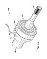
- Fig. 4B is a perspective view 400B of the speed sensor bearing unit 401 mounted on the output shaft 26.
- the second set of bearings 401 resides between spindle bracket 14 and output shaft 26.
- the second set of bearings 401 includes a speed and direction sensor integral therewith for detecting the speed and direction of rotation of the output shaft 26.
- the second set of bearings 401 includes an inner race 403 and an outer race 405 and a plurality of ball bearings 404.
- Inner race 403 is affixed to the output shaft 26 and rotatable therewith and outer race 405 is stationary.
- a magnetized impulse ring 413 is affixed to the inner race 403 and is rotatable therewith as shaft 26 rotates.
- a sensor body 414 is affixed to the outer race 405 of the second set of bearings 401 which detects the magnetic impulses provided when the inner impulse ring 413 and the shaft 26 are rotating.
- a cable 402, 408 leads from the sensor 401 to communicate with a control system illustrate in Fig. 4C .
- Reference numeral 408 indicates the external portion of the cable which extends from the motor housing as illustrated in Fig. 4 .
- the sensor-bearing units 401 are specially designed incremental encoders for motor control and they are produced by SKF Mechatronics.
- the SKF Mechatronics sensor is being set forth herein by way of example only and many different sensors and different types of sensors may be used.
- the sensor-bearing units 401 provide compact and reliable encoding which is subsequently processed and then used in a control system.
- the sensor-bearing units employed herein are intended for applications with a rotating inner ring and stationary outer ring.
- the sensor bearing unit 401 incorporates an active sensor designed to be compact and resides very close to an incremental encoder.
- the sensor's main components are the impulse ring, the sensor body with the sensors and the connecting cable.
- the composite magnetized impulse ring is attached to the stationary bearing inner race which is divided into a certain number of north and south poles.
- the sensor body is attached to the bearing outer race.
- the sensor body has two sensing cells for measuring and counting the rotation of the shaft in two different rotational directions.
- the sensor requires an external voltage supply.
- the sensor outputs two different square waves and depending on which signal is leading, the direction of rotation is determined and the speed of rotation of is determined.
- a substantially cylindrical wheel hub 58 is mounted to the spindle bracket 14 for rotation about a horizontal axis coincident with the axis of rotation of the output shaft 26.
- the wheel hub includes an exterior surface 55 to which a wheel can be mounted, an interior surface 59 surrounding the interior portion of the lower end of the spindle bracket 14, an interior edge 465 between the exterior 58 and interior 59 surfaces, and, an exterior edge 466 between the exterior 58 and interior 59 surfaces.
- the hub 58 is supported for rotation by a third set of bearings 62 positioned adjacent the interior edge 466 of the hub, and a fourth set of bearings 60 positioned inwardly from the exterior edge 465 of the hub.
- a multi-stage planetary gear system is mounted around the output shaft 26 of the motor and positioned within the interior portion of the spindle bracket 14 and within the cylindrical wheel hub 58 between the exterior edge 466 and the interior edge 465.
- the planetary gear system includes an input sun gear 36 positioned between the fourth set of bearings 60 and the exterior edge 466 of the hub 58 and mounted on the output shaft 26 of the motor.
- Input sun gear 36 includes an exterior spline which engages exterior spline 412 of output shaft 26.
- Input sun gear 36 includes a proximate portion 36B and a distal portion 36A.
- Input sun gear 36 is sometimes referred to herein as a "first" sun gear.
- Proximate refers to the side (or point) closest the motor and distal refers to the side (or point) farthest from the motor.
- the planetary gear system further includes input planetary gears 40, a first ring gear 61 affixed to the interior portion of the wheel hub 58, an input gear carrier 46 including a splined interior 46A, and, an output sun gear 48 including a splined exterior 48S.
- the input planetary gears 40 are referred to as the first planetary gears.
- the input gear carrier 46 is referred to as the first carrier.
- the output sun gear 48 includes a proximate portion 48C and a distal portion 48B.
- the output sun gear is mounted for rotation about the output shaft.
- a thrust washer 406 resides between the spindle bracket 14 and the proximate end 48C of the output sun gear 48.
- the proximate portion 48C of the output sun gear 48 interengages the thrust washer 406 and the distal portion 48B of the output sun gear 48 interengages the proximate portion 36B of the input sun gear 36.
- An end cover 70 is affixed to the wheel hub 58 and is rotatable therewith.
- the end cover of the wheel hub includes an interior, the interior includes a centrally located cylindrical recess 330R therein.
- a circumferential spacer ring 330 and a circumferential bracket 331 reside in the cylindrical recess 330R in the cover.
- the distal portion 36A of the input sun gear 36 interengages the circumferential bracket 331 in the cylindrical recess 330R in the cover.
- shoulder 301 on output shaft 26 must reside at the precise location distally with respect to the motor or another location on the output shaft. Put another way, shoulder 301 on shaft 26 must be located precisely with respect to spindle 14.
- the location of shoulder 301 is important as a corresponding shoulder 48A of output sun gear 48 engages shoulder 301 of output shaft 26 and rotates with respect to output shaft 26.
- the precise location of shoulder 301 on shaft 26 determines whether the generally cylindrically shaped output sun gear 48 fits correctly in the allotted space.
- the output sun gear 48 will fit properly. If the axial location of shoulder 301 is located too far from shoulder 302, then the output sun gear will fit too tightly between shoulder 301 and the proximate end 36B of input sun gear 36. If the axial location of shoulder 301 is not located far enough from shoulder 302, then output sun gear 48 will fit too loosely between shoulder 301 and the proximate end 36B of input sun gear 36.
- the input sun gear 36 rotationally drives the input planetary gears 40 which are in engagement with and react against the first ring gear 42 producing rotation of the input gear carrier 46.
- the splined interior 46A of the input gear carrier 46 interengages the splined exterior 48S of the output sun gear 48.
- the planetary gear system further includes output planetary gears 50 driven by the splined exterior 48S of the output sun gear 48S.
- the output planetary gears are mounted for rotation with respect to the spindle bracket such that rotation of the output sun gear causes the output planetary gears to rotate.
- Reference numeral 407 indicates a seal residing between the output shaft 26 and spindle 14 adjacent washer 406.
- An output ring gear 64 joined to the interior of the wheel hub is positioned between the third set of bearings 62 and the fourth set of bearings 60 and is joined to the interior surface 59 of the wheel hub.
- the output ring gear 64 engages the output planetary gears 50 of the multistage planetary gear system so that rotation of the output planetary gears 50 causes output ring gear 64 and the wheel hub 58 to rotate such that mechanical force through the planetary gear system is applied to the wheel hub.
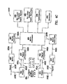
- Fig. 4C is a schematic 400C of the microprocessor 450, speed and direction control sensors 401, 431, the signal processors 420, 440, the motor controllers 422, 442, the motors 423, 443 and the respective outputs for both wheels.
- Fig. 4C illustrates the operation of a 2 wheel drive system. Four wheel drive systems are specifically contemplated.
- the speed and direction sensors 401, 431 output two square wave signals 401A, 431A, 401 B, 431 B which are out of phase as designated by phase angle, [], (REFERENCE NUMERAL 499) with respect to each other.
- the direction of shaft 26 is determined by the relationship between the output signals 401A, 401 B of the bearing unit sensor.
- a signal processor 420, 440 adapts the square wave signals for input into the microprocessor 450.
- the microprocessor 450 receives the adapted square wave signals.
- An operator input station applies the desired wheel hub speed 490 and direction 491 to the microprocessor 450.
- the microprocessor 450 receives the adapted square wave signals 420A, 440A and compares the square wave signals to the desired wheel hub speed 490 and direction 491 input signals and outputs a corrective control signal 450A, 450B according to an algorithm. Any number of algorithms may be used and the algorithms may be used to protect the motor and to protect the operator of the equipment.
- the microprocessor 450 sometimes referred to herein as an embedded microcontroller or embedded microprocessor, protects the motors.
- a motor controller 422, 442 receives and processes the corrective control signal 450A, 450B from the microprocessor 450 and outputs a control signal 422A, 442A to the electric motor 423, 442 dictating the speed and direction of the output shaft.
- Sensors 401, 431 detect the speed and direction 423F, 443F of the motor 423, 443.
Landscapes
- Engineering & Computer Science (AREA)
- Chemical & Material Sciences (AREA)
- Combustion & Propulsion (AREA)
- Transportation (AREA)
- Mechanical Engineering (AREA)
- Retarders (AREA)
- Power Steering Mechanism (AREA)
Applications Claiming Priority (1)
| Application Number | Priority Date | Filing Date | Title |
|---|---|---|---|
| US13/050,895 US8449424B2 (en) | 2011-03-17 | 2011-03-17 | Integral electric motor with speed sensor, planetary gearbox and steering means |
Publications (2)
| Publication Number | Publication Date |
|---|---|
| EP2500199A2 true EP2500199A2 (de) | 2012-09-19 |
| EP2500199A3 EP2500199A3 (de) | 2014-09-03 |
Family
ID=44117684
Family Applications (1)
| Application Number | Title | Priority Date | Filing Date |
|---|---|---|---|
| EP11164656.8A Withdrawn EP2500199A3 (de) | 2011-03-17 | 2011-05-03 | Integrierter Elektromotor mit Geschwindigkeitssensor, Planetengetriebe und Lenkmittel |
Country Status (11)
| Country | Link |
|---|---|
| US (1) | US8449424B2 (de) |
| EP (1) | EP2500199A3 (de) |
| KR (1) | KR200475811Y1 (de) |
| CN (1) | CN202384908U (de) |
| AU (1) | AU2011202097B1 (de) |
| BR (1) | BRPI1104780A2 (de) |
| CA (1) | CA2742221C (de) |
| RU (1) | RU114439U1 (de) |
| SG (1) | SG184607A1 (de) |
| TW (1) | TWM423400U (de) |
| ZA (1) | ZA201104964B (de) |
Cited By (1)
| Publication number | Priority date | Publication date | Assignee | Title |
|---|---|---|---|---|
| CN106696593A (zh) * | 2017-01-06 | 2017-05-24 | 苏州凤凰动力工业有限公司 | 带减速机构的麦克纳姆轮 |
Families Citing this family (43)
| Publication number | Priority date | Publication date | Assignee | Title |
|---|---|---|---|---|
| US8863885B2 (en) * | 2009-10-02 | 2014-10-21 | Volvo Lastvagnar Ab | Wheel hub unit |
| GB201104917D0 (en) * | 2011-03-24 | 2011-05-04 | Qinetiq Ltd | Gear reduction mechanism |
| AU2013202301B2 (en) | 2012-10-25 | 2015-10-01 | Auburn Gear, Inc. | Wheel drive transmission unit |
| US9638285B2 (en) * | 2013-11-14 | 2017-05-02 | Razor Usa Llc | Hub motor arrangement or vehicle with hub motor arrangement |
| US9660500B2 (en) | 2013-11-14 | 2017-05-23 | Razor Usa Llc | Hub motor arrangement or vehicle with hub motor arrangement |
| FR3029466B1 (fr) * | 2014-12-03 | 2018-03-23 | Moteurs Leroy-Somer | Dispositif d'entrainement pour chariot ou analogue |
| US9511661B2 (en) | 2015-03-12 | 2016-12-06 | Deere & Company | Driven wheel unit including an axially compact two-speed planetary gear drive assembly |
| US20150192207A1 (en) * | 2015-03-19 | 2015-07-09 | Caterpillar Inc. | Shaft seal assembly for final drive system |
| US9618084B2 (en) | 2015-08-25 | 2017-04-11 | Deere & Company | Compact planetary arrangement for final drive |
| USD800198S1 (en) | 2016-01-21 | 2017-10-17 | Auburn Gear, Inc. | Combined electric motor and planetary transmission |
| US9903126B2 (en) | 2016-06-13 | 2018-02-27 | Robert L. Rowsome | Movable scaffold |
| US10766361B2 (en) | 2016-08-15 | 2020-09-08 | Auburn Gear, Inc. | Wheel drive transmission |
| US11307063B2 (en) | 2016-12-23 | 2022-04-19 | Gtc Law Group Pc & Affiliates | Inspection robot for horizontal tube inspection having vertically positionable sensor carriage |
| US12358141B2 (en) | 2016-12-23 | 2025-07-15 | Gecko Robotics, Inc. | Systems, methods, and apparatus for providing interactive inspection map for inspection robot |
| US12162160B2 (en) | 2016-12-23 | 2024-12-10 | Gecko Robotics, Inc. | System, apparatus and method for improved location identification with prism |
| WO2018119450A1 (en) | 2016-12-23 | 2018-06-28 | Gecko Robotics, Inc. | Inspection robot |
| US10239401B2 (en) | 2017-01-23 | 2019-03-26 | Auburn Gear, Llc | Electric motor and gearing assembly |
| US10272773B2 (en) | 2017-03-06 | 2019-04-30 | Fairfield Manufacturing Company, Inc. | Planetary wheel drive using thrust washer—cover arrangement |
| US10132372B2 (en) | 2017-03-06 | 2018-11-20 | Fairfield Manufacturing Company, Inc. | Planetary wheel drive brake |
| US10093177B2 (en) | 2017-03-06 | 2018-10-09 | Fairfield Manufacturing Company, Inc. | Compact planetary wheel drive |
| US10066735B1 (en) | 2017-03-06 | 2018-09-04 | Fairfield Manufacturing Company, Inc. | Planetary wheel drive single wall lugged output carrier |
| US10495185B2 (en) | 2017-03-06 | 2019-12-03 | Fairfield Manufacturing Company, Inc. | Planetary wheel drive using bushings |
| CN109510390B (zh) * | 2017-09-15 | 2021-07-09 | 日本电产株式会社 | 驱动装置 |
| CN108608859A (zh) * | 2018-03-23 | 2018-10-02 | 北京极智嘉科技有限公司 | 驱动轮及移动机器人 |
| US11220171B2 (en) | 2018-05-30 | 2022-01-11 | Cecil A. Weeramantry | Drivetrain architecture |
| US10876596B1 (en) | 2018-06-29 | 2020-12-29 | Hydro-Gear Limited Partnership | Electric motor with compound planetary gear drive |
| US11166410B1 (en) | 2018-07-23 | 2021-11-09 | Hydro-Gear Limited Partnership | Electric offset planetary drive |
| US11345232B2 (en) | 2018-09-06 | 2022-05-31 | Volvo Construction Equipment Ab | Wheel hub arrangement for a driving wheel of a vehicle |
| EP3934861B1 (de) | 2019-03-08 | 2025-02-26 | Gecko Robotics, Inc. | Prüfroboter |
| KR102645080B1 (ko) * | 2019-06-27 | 2024-03-07 | 에이치엘만도 주식회사 | 인휠 모터용 연결 조립체 및 이를 포함하는 모빌리티 |
| US11511727B2 (en) * | 2019-09-20 | 2022-11-29 | Cnh Industrial America Llc | Caster wheel orientation sensor assembly |
| US11757330B2 (en) | 2019-12-19 | 2023-09-12 | Black & Decker, Inc. | Canned outer-rotor brushless motor for a power tool |
| US11437900B2 (en) | 2019-12-19 | 2022-09-06 | Black & Decker Inc. | Modular outer-rotor brushless motor for a power tool |
| US11597282B1 (en) | 2020-04-07 | 2023-03-07 | Parker-Hannifin Corporation | Closed-loop control of vehicle speed |
| US11865698B2 (en) | 2021-04-20 | 2024-01-09 | Gecko Robotics, Inc. | Inspection robot with removeable interface plates and method for configuring payload interfaces |
| CA3173120A1 (en) | 2021-04-22 | 2022-10-22 | Chase David | Systems, methods, and apparatus for ultra-sonic inspection of a surface |
| CN113147889B (zh) * | 2021-04-27 | 2024-10-29 | 苏州邦弘智能科技有限公司 | 一种转向轮 |
| US12428102B2 (en) | 2021-05-19 | 2025-09-30 | Razor Usa Llc | Motorized mid-drive unit |
| US12240559B2 (en) | 2021-06-18 | 2025-03-04 | Razor Usa Llc | Hub motor arrangements, systems, and methods |
| US12176794B2 (en) | 2021-11-19 | 2024-12-24 | Black & Decker Inc. | Outer-rotor brushless motor for a power tool |
| DE102021213063B4 (de) | 2021-11-22 | 2023-08-03 | Zf Friedrichshafen Ag | Lenkantrieb für eine Lenkachse eines lenkbaren Fahrzeugs, Lenkachse und Flurförderzeug |
| DE102021213067A1 (de) | 2021-11-22 | 2023-05-25 | Zf Friedrichshafen Ag | Lenkantrieb für eine Lenkachse eines lenkbaren Fahrzeugs, Lenkachse und Flurförderzeug |
| WO2023111723A1 (en) * | 2021-12-15 | 2023-06-22 | 3M Innovative Properties Company | Degradable crosslinkers for (meth)acrylic resins and methods thereof |
Citations (1)
| Publication number | Priority date | Publication date | Assignee | Title |
|---|---|---|---|---|
| US6852061B2 (en) | 2002-09-30 | 2005-02-08 | Benjamin Warren Schoon | Planetary gearbox with integral electric motor and steering means. |
Family Cites Families (33)
| Publication number | Priority date | Publication date | Assignee | Title |
|---|---|---|---|---|
| US2726726A (en) | 1950-08-23 | 1955-12-13 | Letourneau Inc | Electric vehicle wheel |
| US3163250A (en) | 1960-06-09 | 1964-12-29 | Raymond Corp | Narrow aisle material handling truck |
| NL281008A (de) | 1961-07-17 | |||
| GB1089755A (en) | 1965-02-03 | 1967-11-08 | Lansing Bagnall Ltd | Improvements in or relating to motor driven trucks |
| FR2066195A5 (de) | 1969-10-21 | 1971-08-06 | Dso Balkancar | |
| US3812928A (en) | 1972-05-12 | 1974-05-28 | Allis Chalmers | Electric powered wheel |
| US3865203A (en) | 1973-03-08 | 1975-02-11 | Hibma Anne Marie | Scaffold drive and steering unit |
| US3892300A (en) | 1973-08-22 | 1975-07-01 | Gen Electric | Motorized wheel brake system |
| CA1039083A (en) | 1975-07-04 | 1978-09-26 | Teijin Seiki Company Limited | Reduction gear driving mechanism |
| US4088202A (en) | 1976-08-25 | 1978-05-09 | Costello Clifford T | Scaffolding cart |
| JPS5610840A (en) * | 1979-07-05 | 1981-02-03 | Imazaike Seikou Kk | Damper |
| US4330045A (en) | 1979-09-14 | 1982-05-18 | Reliance Electric Company | Vehicle wheel mechanism |
| DE3015818C2 (de) | 1980-04-22 | 1982-08-19 | Mannesmann AG, 4000 Düsseldorf | Drehfeste Verbindung eines axial beweglichen Planetenträgers mit einem Zapfen, insbesondere dem Tragzapfen eines hydrostatischen Fahrgetriebes |
| US4930590A (en) | 1989-05-11 | 1990-06-05 | Deere & Company | Motor and transmission assembly |
| JP2849201B2 (ja) | 1990-11-20 | 1999-01-20 | アイシン・エイ・ダブリュ株式会社 | 減速機付ホィールモータ |
| US5087229A (en) | 1991-05-06 | 1992-02-11 | General Motors Corporation | Independently suspended steerable motor wheel apparatus |
| FR2679842A1 (fr) | 1991-07-29 | 1993-02-05 | Shm Management Services Ag | Module de roulement moteur, notamment pour vehicule automobile. |
| DE4421428C1 (de) | 1994-06-18 | 1995-07-27 | Fichtel & Sachs Ag | Mit einem Elektromotor zu einer Baueinheit verbindbares Planetengetriebe |
| US5813488A (en) | 1996-06-14 | 1998-09-29 | Deere & Company | Electric wheel drive for a utility vehicle |
| DE19904552A1 (de) | 1998-03-19 | 1999-09-23 | Linde Ag | Radantrieb für Flurförderzeuge |
| SE516990C2 (sv) | 1998-12-29 | 2002-04-02 | Volvo Car Corp | Arrangemang för hjulupphängning i fordon |
| US6457681B1 (en) * | 2000-12-07 | 2002-10-01 | Mike's Train House, Inc. | Control, sound, and operating system for model trains |
| ITTO20010708A1 (it) * | 2001-07-19 | 2003-01-19 | Skf Ind Spa | Dispositivo di tenuta per cuscinetti. |
| TW577836B (en) | 2002-04-09 | 2004-03-01 | Taiwan Bicycle Ind R&D Center | Control system and method for electromotive vehicle |
| US7100722B2 (en) * | 2002-08-29 | 2006-09-05 | Peerless-Winsmith, Inc. | Wheel assembly including a DC motor mounted within the HUB and drive connected to the wheel |
| JP2007016846A (ja) * | 2005-07-06 | 2007-01-25 | Ntn Corp | インホイールモータの軸受装置 |
| KR100747210B1 (ko) | 2005-08-30 | 2007-08-07 | 현대자동차주식회사 | 엘피아이 엔진 시스템 |
| JP5052084B2 (ja) * | 2006-09-19 | 2012-10-17 | Ntn株式会社 | インホイール型モータ内蔵センサ付きアクスルユニット |
| JP4819633B2 (ja) | 2006-09-26 | 2011-11-24 | ヤマハ発動機株式会社 | 鞍乗型車両用のベルト式無段変速機及び鞍乗型車両 |
| JP2008249353A (ja) * | 2007-03-29 | 2008-10-16 | Ntn Corp | 回転検出装置および回転検出装置付き軸受 |
| TWI330600B (en) | 2008-06-13 | 2010-09-21 | Ind Tech Res Inst | Electric vehicle and control method thereof |
| US8133143B2 (en) * | 2008-06-16 | 2012-03-13 | Fairfield Manufacturing Company, Inc. | Gear reducer electric motor assembly with internal brake |
| JP5436191B2 (ja) * | 2009-12-21 | 2014-03-05 | Ntn株式会社 | インホイール型モータ内蔵センサ付き車輪用軸受装置 |
-
2011
- 2011-03-17 US US13/050,895 patent/US8449424B2/en not_active Expired - Fee Related
- 2011-05-03 EP EP11164656.8A patent/EP2500199A3/de not_active Withdrawn
- 2011-05-06 AU AU2011202097A patent/AU2011202097B1/en not_active Ceased
- 2011-05-19 TW TW100208949U patent/TWM423400U/zh not_active IP Right Cessation
- 2011-06-06 CA CA2742221A patent/CA2742221C/en not_active Expired - Fee Related
- 2011-06-23 KR KR2020110005746U patent/KR200475811Y1/ko not_active Expired - Fee Related
- 2011-07-05 ZA ZA2011/04964A patent/ZA201104964B/en unknown
- 2011-07-27 CN CN2011202687373U patent/CN202384908U/zh not_active Expired - Lifetime
- 2011-08-03 SG SG2011055787A patent/SG184607A1/en unknown
- 2011-08-05 BR BRPI1104780-1A patent/BRPI1104780A2/pt not_active Application Discontinuation
- 2011-08-15 RU RU2011134234/11U patent/RU114439U1/ru not_active IP Right Cessation
Patent Citations (1)
| Publication number | Priority date | Publication date | Assignee | Title |
|---|---|---|---|---|
| US6852061B2 (en) | 2002-09-30 | 2005-02-08 | Benjamin Warren Schoon | Planetary gearbox with integral electric motor and steering means. |
Cited By (1)
| Publication number | Priority date | Publication date | Assignee | Title |
|---|---|---|---|---|
| CN106696593A (zh) * | 2017-01-06 | 2017-05-24 | 苏州凤凰动力工业有限公司 | 带减速机构的麦克纳姆轮 |
Also Published As
| Publication number | Publication date |
|---|---|
| US8449424B2 (en) | 2013-05-28 |
| SG184607A1 (en) | 2012-10-30 |
| KR20120006677U (ko) | 2012-09-27 |
| CN202384908U (zh) | 2012-08-15 |
| TWM423400U (en) | 2012-02-21 |
| EP2500199A3 (de) | 2014-09-03 |
| ZA201104964B (en) | 2012-03-28 |
| AU2011202097B1 (en) | 2012-05-31 |
| CA2742221C (en) | 2013-04-02 |
| US20120238389A1 (en) | 2012-09-20 |
| KR200475811Y1 (ko) | 2015-01-05 |
| RU114439U1 (ru) | 2012-03-27 |
| CA2742221A1 (en) | 2012-09-17 |
| BRPI1104780A2 (pt) | 2013-05-14 |
Similar Documents
| Publication | Publication Date | Title |
|---|---|---|
| CA2742221C (en) | Integral electric motor with speed sensor, planetary gearbox and steering means | |
| AU745277B2 (en) | Drive mechanism for a vehicle, especially a multilane electromobile | |
| US20110016960A1 (en) | Device For Detecting Angular Position, Electric Motor, Steering Column And Reduction Gear | |
| EP2664487A1 (de) | Radinterne motorantriebsvorrichtung | |
| CN210617839U (zh) | 一种快速更换脚轮的agv舵轮 | |
| JP2008260372A (ja) | 車両の操舵制御装置 | |
| JP2012045978A (ja) | 車両用操舵装置 | |
| US4900997A (en) | Device to guide an object around two axes of rotation | |
| CN110039569A (zh) | 一种机器人关节 | |
| JP2013181645A (ja) | 電気自動車用駆動装置 | |
| CN110316278A (zh) | 一种差速驱动舵轮 | |
| CN108566040A (zh) | 一种嵌入式外转电机减速一体机 | |
| JP2017001423A (ja) | 後輪転舵制御装置 | |
| JP5862062B2 (ja) | モータ駆動ユニット | |
| CN101878583A (zh) | 电动机组和齿轮传动装置 | |
| US20080127757A1 (en) | Drive Device | |
| CN109372974B (zh) | 一种带多位置锁紧机构的高精度轴系 | |
| WO2016129436A1 (ja) | 後輪転舵装置 | |
| CN117007041A (zh) | 一种高精度高可靠性锁定装置 | |
| US10053137B2 (en) | Rear wheel steering device | |
| CN212959705U (zh) | 一种舵轮 | |
| CN207758863U (zh) | 一种舵轮驱动装置 | |
| JP3170259U (ja) | 速度センサ、遊星ギアボックス、および操舵手段を備える一体型の電動モータ | |
| US7694601B2 (en) | Gear device and electric power steering apparatus | |
| CN103567469A (zh) | 数控螺旋锥齿轮铣齿机刀具主轴装置 |
Legal Events
| Date | Code | Title | Description |
|---|---|---|---|
| PUAI | Public reference made under article 153(3) epc to a published international application that has entered the european phase |
Free format text: ORIGINAL CODE: 0009012 |
|
| AK | Designated contracting states |
Kind code of ref document: A2 Designated state(s): AL AT BE BG CH CY CZ DE DK EE ES FI FR GB GR HR HU IE IS IT LI LT LU LV MC MK MT NL NO PL PT RO RS SE SI SK SM TR |
|
| AX | Request for extension of the european patent |
Extension state: BA ME |
|
| PUAL | Search report despatched |
Free format text: ORIGINAL CODE: 0009013 |
|
| AK | Designated contracting states |
Kind code of ref document: A3 Designated state(s): AL AT BE BG CH CY CZ DE DK EE ES FI FR GB GR HR HU IE IS IT LI LT LU LV MC MK MT NL NO PL PT RO RS SE SI SK SM TR |
|
| AX | Request for extension of the european patent |
Extension state: BA ME |
|
| RIC1 | Information provided on ipc code assigned before grant |
Ipc: B60K 17/30 20060101ALI20140731BHEP Ipc: B60K 17/04 20060101ALI20140731BHEP Ipc: B60K 7/00 20060101AFI20140731BHEP |
|
| 17P | Request for examination filed |
Effective date: 20141230 |
|
| RAX | Requested extension states of the european patent have changed |
Extension state: BA Payment date: 20141230 Extension state: ME Payment date: 20141230 |
|
| RBV | Designated contracting states (corrected) |
Designated state(s): AL AT BE BG CH CY CZ DE DK EE ES FI FR GB GR HR HU IE IS IT LI LT LU LV MC MK MT NL NO PL PT RO RS SE SI SK SM TR |
|
| STAA | Information on the status of an ep patent application or granted ep patent |
Free format text: STATUS: EXAMINATION IS IN PROGRESS |
|
| 17Q | First examination report despatched |
Effective date: 20170908 |
|
| STAA | Information on the status of an ep patent application or granted ep patent |
Free format text: STATUS: THE APPLICATION IS DEEMED TO BE WITHDRAWN |
|
| 18D | Application deemed to be withdrawn |
Effective date: 20200219 |