EP2500132A1 - Procédé et dispositif de commande de machine-outil - Google Patents
Procédé et dispositif de commande de machine-outil Download PDFInfo
- Publication number
- EP2500132A1 EP2500132A1 EP09851275A EP09851275A EP2500132A1 EP 2500132 A1 EP2500132 A1 EP 2500132A1 EP 09851275 A EP09851275 A EP 09851275A EP 09851275 A EP09851275 A EP 09851275A EP 2500132 A1 EP2500132 A1 EP 2500132A1
- Authority
- EP
- European Patent Office
- Prior art keywords
- machining
- workpiece
- tool
- machining tool
- operating condition
- Prior art date
- Legal status (The legal status is an assumption and is not a legal conclusion. Google has not performed a legal analysis and makes no representation as to the accuracy of the status listed.)
- Withdrawn
Links
Images


Classifications
-
- G—PHYSICS
- G05—CONTROLLING; REGULATING
- G05B—CONTROL OR REGULATING SYSTEMS IN GENERAL; FUNCTIONAL ELEMENTS OF SUCH SYSTEMS; MONITORING OR TESTING ARRANGEMENTS FOR SUCH SYSTEMS OR ELEMENTS
- G05B19/00—Programme-control systems
- G05B19/02—Programme-control systems electric
- G05B19/18—Numerical control [NC], i.e. automatically operating machines, in particular machine tools, e.g. in a manufacturing environment, so as to execute positioning, movement or co-ordinated operations by means of programme data in numerical form
-
- B—PERFORMING OPERATIONS; TRANSPORTING
- B23—MACHINE TOOLS; METAL-WORKING NOT OTHERWISE PROVIDED FOR
- B23Q—DETAILS, COMPONENTS, OR ACCESSORIES FOR MACHINE TOOLS, e.g. ARRANGEMENTS FOR COPYING OR CONTROLLING; MACHINE TOOLS IN GENERAL CHARACTERISED BY THE CONSTRUCTION OF PARTICULAR DETAILS OR COMPONENTS; COMBINATIONS OR ASSOCIATIONS OF METAL-WORKING MACHINES, NOT DIRECTED TO A PARTICULAR RESULT
- B23Q15/00—Automatic control or regulation of feed movement, cutting velocity or position of tool or work
- B23Q15/007—Automatic control or regulation of feed movement, cutting velocity or position of tool or work while the tool acts upon the workpiece
- B23Q15/12—Adaptive control, i.e. adjusting itself to have a performance which is optimum according to a preassigned criterion
-
- B—PERFORMING OPERATIONS; TRANSPORTING
- B23—MACHINE TOOLS; METAL-WORKING NOT OTHERWISE PROVIDED FOR
- B23Q—DETAILS, COMPONENTS, OR ACCESSORIES FOR MACHINE TOOLS, e.g. ARRANGEMENTS FOR COPYING OR CONTROLLING; MACHINE TOOLS IN GENERAL CHARACTERISED BY THE CONSTRUCTION OF PARTICULAR DETAILS OR COMPONENTS; COMBINATIONS OR ASSOCIATIONS OF METAL-WORKING MACHINES, NOT DIRECTED TO A PARTICULAR RESULT
- B23Q17/00—Arrangements for observing, indicating or measuring on machine tools
- B23Q17/09—Arrangements for observing, indicating or measuring on machine tools for indicating or measuring cutting pressure or for determining cutting-tool condition, e.g. cutting ability, load on tool
- B23Q17/0952—Arrangements for observing, indicating or measuring on machine tools for indicating or measuring cutting pressure or for determining cutting-tool condition, e.g. cutting ability, load on tool during machining
- B23Q17/0971—Arrangements for observing, indicating or measuring on machine tools for indicating or measuring cutting pressure or for determining cutting-tool condition, e.g. cutting ability, load on tool during machining by measuring mechanical vibrations of parts of the machine
- B23Q17/0976—Detection or control of chatter
-
- G—PHYSICS
- G05—CONTROLLING; REGULATING
- G05B—CONTROL OR REGULATING SYSTEMS IN GENERAL; FUNCTIONAL ELEMENTS OF SUCH SYSTEMS; MONITORING OR TESTING ARRANGEMENTS FOR SUCH SYSTEMS OR ELEMENTS
- G05B2219/00—Program-control systems
- G05B2219/30—Nc systems
- G05B2219/37—Measurements
- G05B2219/37434—Measuring vibration of machine or workpiece or tool
-
- G—PHYSICS
- G05—CONTROLLING; REGULATING
- G05B—CONTROL OR REGULATING SYSTEMS IN GENERAL; FUNCTIONAL ELEMENTS OF SUCH SYSTEMS; MONITORING OR TESTING ARRANGEMENTS FOR SUCH SYSTEMS OR ELEMENTS
- G05B2219/00—Program-control systems
- G05B2219/30—Nc systems
- G05B2219/37—Measurements
- G05B2219/37435—Vibration of machine
-
- G—PHYSICS
- G05—CONTROLLING; REGULATING
- G05B—CONTROL OR REGULATING SYSTEMS IN GENERAL; FUNCTIONAL ELEMENTS OF SUCH SYSTEMS; MONITORING OR TESTING ARRANGEMENTS FOR SUCH SYSTEMS OR ELEMENTS
- G05B2219/00—Program-control systems
- G05B2219/30—Nc systems
- G05B2219/45—Nc applications
- G05B2219/45147—Machining blade, airfoil
Definitions
- the present invention relates to a machine tool control method and a machine tool control device that prevent chatter vibrations from occurring during machining of a workpiece in a machine tool that performs cutting and the like.
- chatter vibrations For example, during cutting, when vibrations of a machining tool in operation resonate with natural vibrations of a workpiece, chatter vibrations are caused.
- the chatter vibrations cause problems such as deteriorated machining surface roughness of the workpiece and damaged cutting edges of the machining tool due to the vibrations.
- Patent Literature 1 A method that enables to solve the problems caused by the chatter vibrations is described in Patent Literature 1, for example.
- This method includes obtaining vibration data for a workpiece at a current process, estimating whether chatter vibrations will occur at the next process with higher finishing precision by using the obtained vibration data, and modifying machining data for machining the workpiece at the next process based on a result of the estimation as to whether chatter vibrations will occur.
- chatter vibrations have occurred in the workpiece at each process, the chatter vibrations at the process are suppressed based on the vibration data for the workpiece, which is obtained at each process.
- the chatter vibrations that have occurred in the workpiece are suppressed by increasing a feed rate of the machining tool, decreasing a cutting speed (the number of revolutions) of the machining tool relative to the workpiece, or decreasing a cutting amount of the machining tool with respect to the workpiece.
- Patent Literature 1 Japanese Patent Application Laid-open No. 2006-150504
- chatter vibrations cannot always be prevented from occurring. This is because natural vibrations of a workpiece change with changes in mass and rigidity of the workpiece during cutting. Thus, during machining of the workpiece, natural vibrations of the machining tool resonate with the natural vibrations of the workpiece, which causes chatter vibrations.
- operating conditions of the machining tool such as the feed rate, the number of revolutions, and the cutting amount of the machining tool, are changed to suppress the chatter vibrations.
- the present invention has been achieved in view of the above problems, and an object of the invention is to provide a machine tool control method and a machine tool control device that enable to improve machining surface roughness of a workpiece and reduce machining costs.
- a machine tool control method includes: a step of setting natural vibrations of a workpiece to be obtained before and after machining of the workpiece, and setting vibration components of a machining tool to be generated during machining; a step of determining an operating condition of the machining tool out of a range where the vibration components of the machining tool resonate with the natural vibrations of the workpiece within a region of the natural vibrations between before and after the machining; and a step of performing machining of the workpiece based on the determined operating condition of the machining tool.
- the machine tool control method performs machining of the workpiece under the operating condition of the machining tool, in which the vibration components of the machining tool do not resonate with the natural vibrations of the workpiece even in a region where the mass and rigidity of the workpiece change during the machining of the workpiece, which prevents chatter vibrations from occurring. Consequently, there is no need to change the operating condition of the machining tool during machining of the workpiece to suppress chatter vibrations. This improves machining surface roughness of the workpiece, and reduces machining costs because its machining time is not increased.
- the operating condition of the machining tool is number of revolutions of the machining tool with a feed rate and a cutting amount of the machining tool being constant.
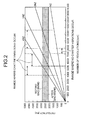
- the natural vibrations of the workpiece and the vibration components of the machining tool to be generated during the machining are set on a Campbell diagram.
- a machine tool control device includes: a setting unit that sets natural vibrations of a workpiece to be obtained before and after machining of the workpiece, and sets vibration components of a machining tool to be generated during the machining; a determining unit that determines an operating condition of the machining tool out of a range where the vibration components of the machining tool resonate with the natural vibrations of the workpiece within a region of the natural vibrations between before and after the machining; and a control unit that performs machining of the workpiece based on the determined operating condition of the machining tool.
- the machine tool control device performs machining of the workpiece under the operating condition of the machining tool, in which the vibration components of the machining tool do not resonate with the natural vibrations of the workpiece even in a region where the mass and rigidity of the workpiece change during the machining of the workpiece, which prevents chatter vibrations from occurring. Consequently, there is no need to change the operating condition of the machining tool during machining of the workpiece to suppress chatter vibrations. This improves machining surface roughness of the workpiece, and reduces machining costs because its machining time is not increased.
- chatter vibrations are prevented from occurring, thereby avoiding a situation where an operating condition of a machining tool is changed during machining of a workpiece. This improves machining surface roughness of the workpiece, and prevents increase in the machining time to reduce machining costs.
- FIG. 1 is a schematic configuration diagram of a machine tool according to an embodiment of the present invention and a control device therefor.
- FIG. 2 is a Campbell diagram for determining an operating condition of a machining tool.
- FIG. 3 is a flowchart of an operation (a control method) of the control device for the machine tool shown in FIG. 1 .
- a workpiece machining device 1 as a machine tool includes a machining unit 2 and a control device 4.
- a bed 21 is provided at a bottom of the machining unit 2.
- a gate-shaped column 22 stands on the bed 21.
- a saddle 25 is supported on a front surface of the column 22 reciprocatably through guides 23 and 24 extending in the X-axis direction (left-right direction).
- a spindle head 27 is supported on a front surface of the saddle 25 through a guide 26 extending in the Z-axis direction (vertical direction) along which the spindle head 27 can move up and down.
- a machining head 28 is supported on an undersurface of the spindle head 27 rotatably about a rotation axis P.
- a machining tool T is held at the machining head 28.
- the machining head 28 has a damper 28a that absorbs contact pressure generated when the machining tool T contacts with a workpiece W.
- a table 30 is supported on the bed 21 slidably through a guide 29 extending in the Y-axis direction (front-rear direction).
- a workpiece holding unit 31 that holds the workpiece W is provided on the table 30.
- the workpiece W shown in FIG. 1 exemplifies a turbine blade to be used for a gas turbine or the like.
- the machining unit 2 is configured to move the machining tool T in the X-axis direction (left-right direction) and the Z-axis direction (vertical direction), and move the workpiece W in the Y-axis direction (front-rear direction).
- the movements in the X-axis, Z-axis, and Y-axis directions are driven by a moving-mechanism driving unit 46 mentioned below.
- the machining unit 2 is also configured to rotate the machining tool T about the rotation axis P.
- the rotation of the machining tool T is driven by a machining-tool-rotation driving unit 47 mentioned below.
- the workpiece machining device 1 moves the machining tool T in the X-axis and Z-axis directions while rotating the machining tool T about the rotation axis P, and moves the workpiece W in the Y-axis direction to bring the machining tool T into contact with the workpiece W, thereby performing cutting of the workpiece W.
- the control device 4 includes a microcomputer and the like, and controls an operation of the machining unit 2.
- the control device 4 has a control unit 41.
- the control unit 41 connects to a storage unit 42, an input unit 43, a setting unit 44, a determining unit 45, the moving-mechanism driving unit 46, and the machining-tool-rotation driving unit 47.
- the various information input to the input unit 43 includes natural vibrations of the workpiece W, and vibration components of the machining tool T to be generated during machining.
- the natural vibrations of the workpiece W include both of those before and after the machining.
- the natural vibrations of the workpiece W before and after the machining can be obtained by the finite element analysis or experimental modal analysis based on design data for the workpiece W.
- the vibration components of the machining tool T include a frequency component calculated by a product (NZ) of the number [N] of revolutions of the machining tool T and the number [Z] of cutting edges of the machining tool T, and harmonic components of the frequency component.
- the natural vibrations of the workpiece W include those obtained when the workpiece W is machined in a torsion mode and in a bending mode.
- the workpiece W in the torsion mode, load is applied in a torsional direction when a longitudinally central portion of the workpiece W is machined, for example.
- the bending mode load is applied in a bending direction when a longitudinal end of the workpiece W exemplified in FIG. 1 is machined.
- the natural vibrations of the workpiece W are greater, and a difference in the natural vibrations between before and after machining of the workpiece W is greater, and accordingly chatter vibrations are more likely to occur, compared to in the bending mode. Therefore, the natural vibrations obtained when the workpiece W is machined in the torsion mode are described below in the present embodiment.
- the setting unit 44 sets the natural vibrations of the workpiece W and the vibration components of the machining tool T during the machining, which have been input to the input unit 43, on a Campbell diagram shown in FIG. 2 .
- the determining unit 45 refers to the Campbell diagram to determine the operating condition of the machining tool T out of a range where the vibration components of the machining tool T resonate with the natural vibrations of the workpiece W within a region of the natural vibrations between before and after the machining.
- the number of revolutions of the machining tool T is defined as the operating condition of the machining tool T with the feed rate and the cutting amount of the machining tool T being constant. Because the number of revolutions of the machining tool T is used to determine the vibration components of the machining tool T, the number of revolutions is more preferable as the operating condition.
- control unit 41 controls the moving-mechanism driving unit 46 and the machining-tool-rotation driving unit 47 primarily based on the operating condition of the machining tool T, which is determined by the determining unit 45.
- control a control method of the workpiece machining device 1 by the control device 4 is described below.
- the natural vibrations of the workpiece W before and after machining of the workpiece W are first input to the input unit 43 (Step S1).
- the setting unit 44 sets a region of the natural vibrations of the workpiece W between before and after the machining on the Campbell diagram (Step S2).
- the vertical axis represents the frequency [Hz] while the horizontal axis represents the number of revolutions [rpm].
- the setting unit 44 sets the region (hatched area) of the natural vibrations of the workpiece W between before and after the machining on the Campbell diagram.
- the vibration components of the machining tool T during the machining are input to the input unit 43 (Step S3).
- the setting unit 44 sets the vibration components of the machining tool T during the machining on the Campbell diagram (Step S4).
- the setting unit 44 sets the frequency component calculated by the product (NZ) of the number [N] of revolutions of the machining tool T and the number [Z] of cutting edges of the machining tool T, and harmonic components (2NZ, 3NZ, 4NZ...) of the frequency component as the vibration components of the machining tool T during the machining on the Campbell diagram, as shown in FIG. 2 .
- the natural vibrations of the workpiece W and the vibration components of the machining tool T during the machining are set on the Campbell diagram so that the determination of the number of revolutions of the machining tool T is confirmed easily.
- the determining unit 45 then refers to the Campbell diagram to determine the number of revolutions of the machining tool T out of a range where the vibration components of the machining tool T resonate with the natural vibrations of the workpiece W within the region of the natural vibrations between before and after the machining (Step S5). This obtains a range of the number of revolutions where no chatter vibrations occur, as shown in FIG. 2 .
- the control unit 41 then controls the machining-tool-rotation driving unit 47 based on the number of revolutions (operating condition) of the machining tool T while controlling the moving-mechanism driving unit 46, to perform machining of the workpiece W (Step S6), and then this control is finished.
- Steps S1 and S2 and Steps S3 and S4 can be performed in the reverse order. That is, it is possible to input first the vibration components of the machining tool T during the machining (Step S3) and set the vibration components of the machining tool T during the machining on the Campbell diagram (Step S4), and then input the natural vibrations of the workpiece W before and after the machining (Step S1) and set the region of the natural vibrations of the workpiece W between before and after the machining on the Campbell diagram (Step S2).
- the machine tool control method and the machine tool control device enable to determine the number of revolutions (operating condition) of the machining tool T out of the range where the vibration components of the machining tool T resonate with the natural vibrations of the workpiece W within the region of the natural vibrations between before and after the machining, and perform machining of the workpiece W based on the determined number of revolutions of the machining tool T.
- machining of the workpiece W is performed at the number of revolutions of the machining tool T, at which the vibration components of the machining tool T do not resonate with the natural vibrations of the workpiece W, even in a region where the mass and rigidity of the workpiece W change during the machining of the workpiece W. This prevents chatter vibrations from occurring.
- the machine tool control method and the machine tool control device according to the present invention are suitable for improving the machining surface roughness of the workpiece and reducing the machining costs.
Applications Claiming Priority (1)
| Application Number | Priority Date | Filing Date | Title |
|---|---|---|---|
| PCT/JP2009/069342 WO2011058645A1 (fr) | 2009-11-13 | 2009-11-13 | Procédé et dispositif de commande de machine-outil |
Publications (2)
| Publication Number | Publication Date |
|---|---|
| EP2500132A1 true EP2500132A1 (fr) | 2012-09-19 |
| EP2500132A4 EP2500132A4 (fr) | 2013-05-29 |
Family
ID=43991323
Family Applications (1)
| Application Number | Title | Priority Date | Filing Date |
|---|---|---|---|
| EP09851275.9A Withdrawn EP2500132A4 (fr) | 2009-11-13 | 2009-11-13 | Procédé et dispositif de commande de machine-outil |
Country Status (5)
| Country | Link |
|---|---|
| US (1) | US20120226374A1 (fr) |
| EP (1) | EP2500132A4 (fr) |
| KR (1) | KR101354859B1 (fr) |
| CN (1) | CN102596495A (fr) |
| WO (1) | WO2011058645A1 (fr) |
Families Citing this family (8)
| Publication number | Priority date | Publication date | Assignee | Title |
|---|---|---|---|---|
| CN102416580A (zh) * | 2011-12-07 | 2012-04-18 | 常州市新特力工具有限公司 | 镗床的控制装置 |
| JP5851910B2 (ja) * | 2012-03-29 | 2016-02-03 | 三菱重工業株式会社 | 工作機械の制御方法、及び工作機械 |
| CN103372787A (zh) * | 2012-04-28 | 2013-10-30 | 台中精机厂股份有限公司 | 工具机智能化适应性切削振动抑制方法与系统 |
| FR3014717B1 (fr) * | 2013-12-17 | 2016-01-29 | Eads Europ Aeronautic Defence | Dispositif de controle du percage ou du fraisurage d'une piece de haute-precision |
| CN107052894A (zh) * | 2017-04-21 | 2017-08-18 | 李其龙 | 一种消除共振的装置及数控车床 |
| JP6959278B2 (ja) * | 2019-02-27 | 2021-11-02 | ファナック株式会社 | びびり振動判定装置、機械学習装置及びシステム |
| JP2022039715A (ja) * | 2020-08-28 | 2022-03-10 | キヤノン株式会社 | 制御装置、インプリント装置および物品製造方法 |
| CN116638643B (zh) * | 2023-06-27 | 2024-02-06 | 沈阳和研科技股份有限公司 | 一种划片机共振的解决方法 |
Citations (1)
| Publication number | Priority date | Publication date | Assignee | Title |
|---|---|---|---|---|
| EP1296210A1 (fr) * | 2000-06-30 | 2003-03-26 | Mori Seiki Co., Ltd. | Dispositif et procede de simulation d'operations d'usinage pour machines a commande numerique |
Family Cites Families (14)
| Publication number | Priority date | Publication date | Assignee | Title |
|---|---|---|---|---|
| JPS59150903A (ja) * | 1983-02-09 | 1984-08-29 | Toshiba Corp | 回転機械の翼配列構造 |
| US5816122A (en) * | 1996-04-30 | 1998-10-06 | General Dynamics Advanced Technology Systems, Inc. | Apparatus and method for adaptive suppression of vibrations in mechanical systems |
| US6241435B1 (en) * | 1998-03-25 | 2001-06-05 | Vought Aircraft Industries, Inc. | Universal adaptive machining chatter control fixture |
| JPH11300578A (ja) * | 1998-04-21 | 1999-11-02 | Toshiba Mach Co Ltd | 工作機械の数値制御装置 |
| JP4075361B2 (ja) * | 2001-11-27 | 2008-04-16 | 東ソー株式会社 | Mg含有ITOスパッタリングターゲットの製造方法 |
| US6810302B2 (en) * | 2003-03-31 | 2004-10-26 | Sikorsky Aircraft Corporation | Process and methodology for selecting cutting parameters for titanium |
| JP2005074569A (ja) * | 2003-09-01 | 2005-03-24 | Mitsubishi Heavy Ind Ltd | プログラム、コンピュータ装置、多軸加工機、ncプログラムの生成方法、ワークの加工方法 |
| JP2006150504A (ja) | 2004-11-29 | 2006-06-15 | Mitsubishi Heavy Ind Ltd | びびり振動予測防止加工装置、びびり振動予測防止加工装置のびびり振動予測防止方法 |
| JP2006159345A (ja) * | 2004-12-07 | 2006-06-22 | Fanuc Ltd | 制御装置 |
| US20080105094A1 (en) * | 2004-12-20 | 2008-05-08 | Renishaw Plc | Machine and Control System |
| DE102005023317A1 (de) * | 2005-05-20 | 2006-11-23 | P & L Gmbh & Co. Kg | Verfahren zur Schwingungsoptimierung einer Werkzeugmaschine |
| DE102005057175B4 (de) * | 2005-11-30 | 2009-03-26 | Siemens Ag | Verfahren zur Reduktion von Schwingungen eines Maschinenelements und/oder eines Werkstücks |
| IL177336A (en) * | 2006-08-07 | 2013-05-30 | Hanita Metal Works Ltd | Anti-vibration stabilized finger milling |
| JP5536611B2 (ja) * | 2010-10-15 | 2014-07-02 | オークマ株式会社 | 工作機械のモニタ方法及びモニタ装置、工作機械 |
-
2009
- 2009-11-13 EP EP09851275.9A patent/EP2500132A4/fr not_active Withdrawn
- 2009-11-13 KR KR1020127011551A patent/KR101354859B1/ko not_active IP Right Cessation
- 2009-11-13 CN CN2009801624279A patent/CN102596495A/zh active Pending
- 2009-11-13 US US13/505,983 patent/US20120226374A1/en not_active Abandoned
- 2009-11-13 WO PCT/JP2009/069342 patent/WO2011058645A1/fr active Application Filing
Patent Citations (1)
| Publication number | Priority date | Publication date | Assignee | Title |
|---|---|---|---|---|
| EP1296210A1 (fr) * | 2000-06-30 | 2003-03-26 | Mori Seiki Co., Ltd. | Dispositif et procede de simulation d'operations d'usinage pour machines a commande numerique |
Non-Patent Citations (4)
| Title |
|---|
| BRAVO ET AL: "Stability limits of milling considering the flexibility of the workpiece and the machine", INTERNATIONAL JOURNAL OF MACHINE TOOL DESIGN AND RESEARCH, PERGAMON PRESS, OXFORD, GB, vol. 45, no. 15, 1 December 2005 (2005-12-01), pages 1669-1680, XP005084069, ISSN: 0020-7357, DOI: 10.1016/J.IJMACHTOOLS.2005.03.004 * |
| MANE ET AL: "Stability-based spindle speed control during flexible workpiece high-speed milling", INTERNATIONAL JOURNAL OF MACHINE TOOL DESIGN AND RESEARCH, PERGAMON PRESS, OXFORD, GB, vol. 48, no. 2, 31 October 2007 (2007-10-31), pages 184-194, XP022323197, ISSN: 0020-7357 * |
| See also references of WO2011058645A1 * |
| YONG ZHOU ET AL: "Torsion Vibration Analysis of Lead-screw Feed Drives with Changeable Table Position and Work-piece Mass", MECHATRONICS AND AUTOMATION, 2007. ICMA 2007. INTERNATIONAL CONFERENCE ON, IEEE, PI, 1 August 2007 (2007-08-01), pages 2194-2199, XP031135088, ISBN: 978-1-4244-0827-6 * |
Also Published As
| Publication number | Publication date |
|---|---|
| KR101354859B1 (ko) | 2014-01-22 |
| EP2500132A4 (fr) | 2013-05-29 |
| US20120226374A1 (en) | 2012-09-06 |
| KR20120079136A (ko) | 2012-07-11 |
| CN102596495A (zh) | 2012-07-18 |
| WO2011058645A1 (fr) | 2011-05-19 |
Similar Documents
| Publication | Publication Date | Title |
|---|---|---|
| EP2500132A1 (fr) | Procédé et dispositif de commande de machine-outil | |
| JP5258921B2 (ja) | 工作機械及びその加工制御装置 | |
| JP6143222B2 (ja) | 工作機械の異常診断装置及び異常診断方法 | |
| JP2012213830A5 (fr) | ||
| JP5507410B2 (ja) | 工作機械における主軸回転速度のモニタ方法及びモニタ装置、工作機械 | |
| JP6439542B2 (ja) | 数値制御装置と制御方法 | |
| US9662727B2 (en) | Machine tool for threading processes | |
| US9690283B2 (en) | Machine tool for a threading process | |
| JP4848393B2 (ja) | 工作機械の制御方法および制御装置 | |
| WO2016059729A1 (fr) | Dispositif de diagnostic de processus de coupe par vibrations | |
| WO2015037143A1 (fr) | Procédé d'évaluation de trajectoire d'outil et procédé et dispositif de génération de trajectoire d'outil | |
| CN111002088B (zh) | 机床 | |
| JP5543890B2 (ja) | 工具摩耗検出方法及び工作機械 | |
| WO2020085451A1 (fr) | Machine-outil et dispositif de commande | |
| JP5226484B2 (ja) | びびり振動抑制方法 | |
| JP6302794B2 (ja) | 回転速度表示方法 | |
| JP2016190276A (ja) | 数値制御装置と制御方法 | |
| KR102128553B1 (ko) | 공작기계의 진동 제어 방법 | |
| JP6735266B2 (ja) | 工作機械、加工方法、および加工プログラム | |
| CN111230586B (zh) | 控制装置以及控制方法 | |
| JP2014061568A (ja) | びびり振動抑制方法および工作機械 | |
| JP5666397B2 (ja) | 工作機械 | |
| JP2019000943A (ja) | 工作機械、加工方法、および加工プログラム | |
| JPWO2019123593A1 (ja) | 数値制御装置 | |
| JP7039772B1 (ja) | 表示装置、工作機械、および表示方法 |
Legal Events
| Date | Code | Title | Description |
|---|---|---|---|
| PUAI | Public reference made under article 153(3) epc to a published international application that has entered the european phase |
Free format text: ORIGINAL CODE: 0009012 |
|
| 17P | Request for examination filed |
Effective date: 20120420 |
|
| AK | Designated contracting states |
Kind code of ref document: A1 Designated state(s): AT BE BG CH CY CZ DE DK EE ES FI FR GB GR HR HU IE IS IT LI LT LU LV MC MK MT NL NO PL PT RO SE SI SK SM TR |
|
| DAX | Request for extension of the european patent (deleted) | ||
| A4 | Supplementary search report drawn up and despatched |
Effective date: 20130503 |
|
| RIC1 | Information provided on ipc code assigned before grant |
Ipc: B23Q 17/09 20060101ALI20130425BHEP Ipc: G05B 19/18 20060101ALI20130425BHEP Ipc: B23Q 15/12 20060101AFI20130425BHEP |
|
| STAA | Information on the status of an ep patent application or granted ep patent |
Free format text: STATUS: THE APPLICATION HAS BEEN WITHDRAWN |
|
| 18W | Application withdrawn |
Effective date: 20130913 |