EP2500100B1 - Dispositif d'entraînement et dispositif de machine de travail - Google Patents
Dispositif d'entraînement et dispositif de machine de travail Download PDFInfo
- Publication number
- EP2500100B1 EP2500100B1 EP20120159842 EP12159842A EP2500100B1 EP 2500100 B1 EP2500100 B1 EP 2500100B1 EP 20120159842 EP20120159842 EP 20120159842 EP 12159842 A EP12159842 A EP 12159842A EP 2500100 B1 EP2500100 B1 EP 2500100B1
- Authority
- EP
- European Patent Office
- Prior art keywords
- drive device
- gear
- drive
- pumps
- pulley
- Prior art date
- Legal status (The legal status is an assumption and is not a legal conclusion. Google has not performed a legal analysis and makes no representation as to the accuracy of the status listed.)
- Not-in-force
Links
- 230000008878 coupling Effects 0.000 claims description 58
- 238000010168 coupling process Methods 0.000 claims description 58
- 238000005859 coupling reaction Methods 0.000 claims description 58
- 239000012530 fluid Substances 0.000 description 28
- 230000005540 biological transmission Effects 0.000 description 17
- 238000000034 method Methods 0.000 description 7
- 238000010276 construction Methods 0.000 description 5
- 230000001419 dependent effect Effects 0.000 description 3
- 230000001133 acceleration Effects 0.000 description 2
- 238000013016 damping Methods 0.000 description 2
- 238000009434 installation Methods 0.000 description 2
- 230000002238 attenuated effect Effects 0.000 description 1
- 238000001816 cooling Methods 0.000 description 1
- 230000007423 decrease Effects 0.000 description 1
- 238000005265 energy consumption Methods 0.000 description 1
- 238000005516 engineering process Methods 0.000 description 1
- 210000003746 feather Anatomy 0.000 description 1
- 230000007257 malfunction Effects 0.000 description 1
- 238000000926 separation method Methods 0.000 description 1
- 238000004904 shortening Methods 0.000 description 1
- 230000001360 synchronised effect Effects 0.000 description 1
- 238000011144 upstream manufacturing Methods 0.000 description 1
Images


Classifications
-
- B—PERFORMING OPERATIONS; TRANSPORTING
- B02—CRUSHING, PULVERISING, OR DISINTEGRATING; PREPARATORY TREATMENT OF GRAIN FOR MILLING
- B02C—CRUSHING, PULVERISING, OR DISINTEGRATING IN GENERAL; MILLING GRAIN
- B02C13/00—Disintegrating by mills having rotary beater elements ; Hammer mills
- B02C13/26—Details
- B02C13/30—Driving mechanisms
-
- B—PERFORMING OPERATIONS; TRANSPORTING
- B02—CRUSHING, PULVERISING, OR DISINTEGRATING; PREPARATORY TREATMENT OF GRAIN FOR MILLING
- B02C—CRUSHING, PULVERISING, OR DISINTEGRATING IN GENERAL; MILLING GRAIN
- B02C18/00—Disintegrating by knives or other cutting or tearing members which chop material into fragments
- B02C18/06—Disintegrating by knives or other cutting or tearing members which chop material into fragments with rotating knives
- B02C18/16—Details
- B02C18/24—Drives
Definitions
- the present invention relates to a drive device according to the preamble of claim 1, as well as a working machine device according to the preamble of claim 12.
- the DE 94 00 147 U is considered to be the closest prior art.
- the EP 2 317 097 is considered as state of the art under Article 54 (3) EPC.
- pump transfer cases are provided, both at least one hydraulic pump, and at least one working machine, such as a crusher, drive.
- the hydraulic pump in turn drives, for example, a hydraulic motor, which drives, for example, the chassis of the tree rail.
- the work machine is usually driven by a wedge disk and a corresponding belt drive, wherein between the output of the pump distributor gear and the wedge disk, a fluid coupling is interposed.
- the object of the present invention was therefore to reduce the burden on the drive device in case of failure.
- this object is achieved by a drive device with the characterizing features of claim 1.
- the fluid coupling and the Downstream wedge disk and possibly downstream machine are subjected to a torque or the torque curve are interrupted.
- reacts much faster to a fault and the torque flow between the pump distributor gear and wedge disk or downstream machine can be interrupted quickly by the clutch.
- the clutch for example as a friction clutch, the torque transmission for the downstream components, for example, can be ramped up slowly, so that can represent a predetermined starting over the clutch, whereby, for example, a gentle start-up realized and the life of the drive device can be increased.
- the hydraulic pump is connected via a clutch for transmitting a rotational movement or torque with the pump distributor gearbox.
- the hydraulic pump can be used, for example, to drive a hydraulic motor.
- the hydraulic motor can be used for example for driving wheels or track of a construction machine.
- the hydraulic pump can optionally be switched on and off, for example, to avoid the idling losses of the hydraulic pumps during the actual operation "breaking". This reduces the energy consumption of the entire drive device.
- the drive means is connected via a flexible coupling with the pump distributor gearbox.
- the elastic coupling can once have the function of a "damping clutch” and once that of a “compensating clutch”.
- At least one further hydraulic pump is connected via an associated clutch with the pump distributor gearbox.
- the wedge disk between the clutch and the fluid coupling is arranged, wherein the wedge disk is deposited on bearings on the housing of the pump distributor gear.
- the pump distributor gearbox comprises a gear stage, in particular a one-stage or multi-stage gear stage with a ratio i equal to 1 or i not equal to 1.
- a gear stage in particular a one-stage or multi-stage gear stage with a ratio i equal to 1 or i not equal to 1.
- the fluid coupling is a hydrodynamic coupling operating according to the Föttinger principle.
- the coupling parts of the input and output side are not mechanically connected to each other. Rather, in particular a fluid serves as a torque transmitting means.
- the clutch works wear-free and limits the starting and maximum torque in the drive train. Furthermore, it serves as a start-up aid for the engine, as overload protection in case of failure and for torsional vibration separation.
- the clutch for the wedge plate is received in the housing of the pump distributor gearbox.
- a compact drive means can be provided.
- a friction clutch with suitable for "wet run” coverings is preferably used.
- Wet-running multi-plate clutches for example, build much smaller than dry friction clutches with the same power transmission.
- Wet running linings are considered as appropriate during dynamic acceleration processes Wear / design wear-free, while dry running pads are always subject to wear.
- Another object of the present invention has been to propose an improved working machine device, in particular to propose a working machine device whose loads can be reduced for the working machine device in case of failure.
- the drive device of the working machine device is a drive device according to at least one of claims 1 to 11 enables the advantages of the drive device according to the invention to be used for the working machine device according to the invention , ie the load of the working machine device can be reduced for the accident, since the torque flow through the clutch can be interrupted quickly. Since it is possible to represent a predetermined starting process via the clutch, it is also possible, for example, to realize a gentle starting of the working machine device and to extend its service life.
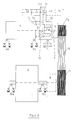
- a drive device essentially comprises a drive means 1, a pump distributor gear 4, a clutch 4a, at least one hydraulic pump 5, a fluid coupling 6, and a wedge disk 7a. Also, the drive means may comprise a further clutch 4b.
- a working machine device essentially comprises a drive device according to the invention, as well as a working machine 9. Furthermore, the working machine device according to the invention comprises a wedge disk 7c and a corresponding belt drive 7b for connection to the wedge disk 7a of the drive device.
- the drive devices described above are usually carried out with a diesel engine or with an electric motor. But also more drive means are possible. The following description is based on the example "Diesel engine as drive means" (see FIG. 1 ).
- the pump distributor gear 4 is flanged.
- the diesel engine 1 is mounted, for example, on the frame of a mobile construction machine (not shown) with corresponding fastening elements 2a / 2b.
- the pump distributor gear 4 can also be fastened to the frame of the construction machine with corresponding fastening elements 2c.
- the pump distributor gear has a housing 12.
- a flexible coupling 3 can be flanged, which in turn is arranged on a transmission input shaft 10 of the pump distributor 4.
- the elastic coupling 3 once has the function of a "damping clutch” and once that of a "compensating clutch".
- the torque flow between the transmission input shaft 10 and a transmission output shaft 11 of the pump distributor gear 4 is to be interrupted or connected with a shiftable clutch 4a.
- the actuation of the switchable couplings 4a / 4b to 4i is not relevant to the function here and can therefore be chosen arbitrarily.
- Common types of operation are hydraulic or pneumatic pressure, electromagnetic force, spring force, mechanical operations, etc.
- the following descriptions refer to couplings that are actuated by hydraulic pressure.
- the transmission input shaft 10 and the transmission output shaft 11 are mounted with bearings in the housing 12 of the pump distributor gear 4.
- On the transmission output shaft 11 of the pump distributor gear 4 is a working according to the "Föttinger principle" fluid coupling 6, also called hydrodynamic coupling (eg, with constant oil filling) plugged.
- the gearbox output torque of the pump distributor gear 4 is thus at the same time the drive torque of the fluid coupling 6.
- the fluid coupling allows the following inertia and possible load moments, which high loads for switchable Couplings mean, for all components, such as the friction elements of the switchable clutch, all torque-transmitting components and connections such as: shafts, gears, feather key connections, screw, clamping set connections, splines, are gently accelerated.
- the wedge plate 7a On the output side of the fluid coupling 6, the wedge plate 7a is attached.
- This wedge disk 7a is spatially seen in the first preferred embodiment of the invention shown here between the pump distributor gear 4 and the fluid coupling 6 and is mounted on the housing 12 of the pump distributor gear 4 via bearings.
- the belt drive 7b can now, as exemplified in FIG. 1 shown, a work machine, such as crusher 9, drive via a second wedge disk 7c.
- flat belts are also considered instead of the V-belts.
- a start-up process with the previously outlined drive device or work machine device can be designed as follows.
- the components used have the following state.
- the diesel engine 1 is not started, the clutch 4a, in particular the switchable Friction clutch 4a, is open, ie without pressure and the torque flow between the transmission input 10 and transmission output 11 is thus interrupted, the machine is preferably load torque-free (in the example described, the crusher 9 is empty) and also the optional, switchable clutches 4b to 4i can be opened ,
- the diesel engine 1 is now started first. Then it is raised to the switch-on speed (eg idle speed, "increased" idle speed, oa) of the switchable clutch 4a.
- the shiftable friction clutch 4a is turned on, that is, the clutch 4a is subjected to hydraulic pressure and the torque transmission between the transmission input shaft 10 and the transmission output shaft 11 is thus produced.
- the unit pump distributor gear 4 and switchable couplings 4a / 4b to 4i is a self-sufficient assembly.
- individual, several or all of the optional switchable clutches 4b to 4i can be switched on in order to drive the hydraulic pump (s) 5 / 5a to 5i).
- the pressure level can now be increased to eg the operating pressure.
- the height of the transmittable torque of the shiftable friction clutch 4a is adjustable.
- the diesel engine 1 can be brought to a higher speed level, eg operating speed.
- the following inertia and possible load moments which mean high loads for switchable clutches, are now gently accelerated for all components.
- the previously described unit is part of a modular system; ie in drive devices in which lower load conditions (lower mass moments of inertia to be accelerated, no or only small load moments, etc.) occur, it is also possible to accomplish the startup process only via the shiftable friction clutch 4a.
- the fluid coupling 6 can be omitted from the unit and the transmission output shaft is connected via adapter flanges directly to the wedge disk 7a.
- the kit offers the use or the waiver of an elastic coupling 3 and / or the switchable clutches 4b to 4i for switching on or off of the hydraulic pump (s).
- a further embodiment of the drive device according to the invention or the working machine device according to the invention is in the Fig. 2 shown.
- the drive device according to Fig. 2 differs from the drive device according to Fig. 1 in that the wedge disk 7a is not arranged between the shifting clutch 4a or the outgoing shaft 11 of the shifting clutch 4a and the fluid coupling 6, but the wedge disc 7a is deposited directly on the fluid coupling 6.
- the output side of the fluid coupling 6 consists of a wedge disk 7 a which is mounted on a hollow shaft of the fluid coupling 6.
- a further embodiment of the drive device according to the invention or the working machine device according to the invention is in the Fig. 3 shown.
- the drive device according to Fig. 3 differs from the drive device according to Fig. 1 and Fig. 2 in that the main drive is no longer guided directly through the pump distributor gearbox 4, but experiences a misalignment with the driving machine via a gear stage (1, 2 or multi-stage with i equal to 1 or i not equal to 1).
- This can analogously to the embodiment according to Fig. 2 , as shown, but also analogous to Fig. 1 , that is, with the arrangement of the wedge disk 7a proposed there, be implemented.
- one of the intermediate shafts could be used to drive a hydraulic pump.
- a reverse operation could be achieved via a further clutch.
Landscapes
- Engineering & Computer Science (AREA)
- Food Science & Technology (AREA)
- Arrangement Of Transmissions (AREA)
- Rotary Pumps (AREA)
Claims (14)
- Dispositif d'entraînement pour un dispositif de machine de travail, comportant au moins- un moyen d'entraînement (1), une boîte de transfert de pompe (4), une pompe hydraulique (5), un accouplement hydraulique (6) et une poulie à courroie trapézoïdale (7a),- le moyen d'entraînement (1) entraînant la boîte de transfert de pompe (4),- la boîte de transfert de pompe (4) entraînant l'au moins une pompe hydraulique (5),- la boîte de transfert de pompe (4) entraînant la poulie à courroie trapézoïdale (7a) par le biais de l'accouplement hydraulique (6),caractérisé en ce
qu'un embrayage de commutation (4a) pouvant être actionné lors du fonctionnement est interposé entre la boîte de transfert de pompe (4) et la poulie à courroie trapézoïdale (7a). - Dispositif d'entraînement selon la revendication 1, caractérisé en ce que l'embrayage de commutation (4a) est monté en amont de l'accouplement hydraulique (6).
- Dispositif d'entraînement selon au moins l'une quelconque des revendications précédentes, caractérisé en ce que la boîte de transfert de pompe comprend un boîtier (12).
- Dispositif d'entraînement selon au moins l'une quelconque des revendications précédentes, caractérisé en ce que la pompe hydraulique (5) est entraînée par la boîte de transfert de pompe (4) par le biais d'un embrayage de commutation (4b).
- Dispositif d'entraînement selon au moins l'une quelconque des revendications précédentes, caractérisé en ce qu'un accouplement élastique (3) est interposé entre le moyen d'entraînement (1) et la boîte de transfert de pompe (4).
- Dispositif d'entraînement selon au moins l'une quelconque des revendications précédentes, caractérisé en ce qu'au moins une pompe hydraulique supplémentaire (5a, 5b, 5i) est reliée à la boîte de transfert de pompe (4) par le biais d'un embrayage de commutation associé (4i).
- Dispositif d'entraînement selon au moins l'une quelconque des revendications précédentes, caractérisé en ce que la poulie à courroie trapézoïdale (7a) est disposée entre l'embrayage de commutation (4a) et l'accouplement hydraulique (6), la poulie à courroie trapézoïdale (7a) étant montée sur le boîtier (12) de la boîte de transfert de pompe (4) par le biais de paliers.
- Dispositif d'entraînement selon au moins l'une quelconque des revendications précédentes, caractérisé en ce que la poulie à courroie trapézoïdale (7a) est montée directement sur l'accouplement hydraulique (6).
- Dispositif d'entraînement selon au moins l'une quelconque des revendications précédentes, caractérisé en ce que la boîte de transfert de pompe comporte un étage de transmission, en particulier un étage de transmission à un ou plusieurs rapports avec un rapport de transmission i égal à 1 ou i différent de 1.
- Dispositif d'entraînement selon au moins l'une quelconque des revendications précédentes, caractérisé en ce que l'accouplement hydraulique est un accouplement hydrodynamique fonctionnant suivant le « principe de Föttinger ».
- Dispositif d'entraînement selon au moins l'une quelconque des revendications précédentes, caractérisé en ce que l'embrayage de commutation (4a) pour la poulie à courroie trapézoïdale (7a) est reçu dans le boîtier (12) de la boîte de transfert de pompe (4).
- Dispositif de machine de travail, comportant un dispositif d'entraînement et une machine de travail (9), caractérisé en ce qu'il s'agit d'un dispositif d'entraînement selon au moins l'une quelconque des revendications 1 à 11.
- Dispositif de machine de travail selon la revendication 12, caractérisé en ce que le dispositif de machine de travail comporte une poulie à courroie trapézoïdale (7c) et un entraînement par courroie (7b), la poulie à courroie trapézoïdale (7c) étant conçue pour l'entraînement de la machine de travail (9) et la poulie à courroie trapézoïdale (7c) de la machine de travail (9) étant reliée à la poulie à courroie trapézoïdale (7a) du dispositif d'entraînement par le biais de l'entraînement par courroie (7b).
- Dispositif de machine de travail selon au moins l'une quelconque des revendications précédentes, caractérisé en ce qu'un arbre, un arbre de cardan, un accouplement d'arbre, une transmission et/ou un accouplement à dents est disposé entre la poulie à courroie trapézoïdale (7c) et la machine de travail.
Applications Claiming Priority (1)
| Application Number | Priority Date | Filing Date | Title |
|---|---|---|---|
| DE102011014530 | 2011-03-18 |
Publications (2)
| Publication Number | Publication Date |
|---|---|
| EP2500100A1 EP2500100A1 (fr) | 2012-09-19 |
| EP2500100B1 true EP2500100B1 (fr) | 2014-03-12 |
Family
ID=45936785
Family Applications (1)
| Application Number | Title | Priority Date | Filing Date |
|---|---|---|---|
| EP20120159842 Not-in-force EP2500100B1 (fr) | 2011-03-18 | 2012-03-16 | Dispositif d'entraînement et dispositif de machine de travail |
Country Status (2)
| Country | Link |
|---|---|
| EP (1) | EP2500100B1 (fr) |
| ES (1) | ES2470319T3 (fr) |
Cited By (2)
| Publication number | Priority date | Publication date | Assignee | Title |
|---|---|---|---|---|
| CN105833945A (zh) * | 2015-02-02 | 2016-08-10 | 西门子公司 | 驱动装置 |
| CN111212689A (zh) * | 2017-10-25 | 2020-05-29 | 克磊镘有限公司 | 用于操作破碎机的驱动系统和用于操作破碎机的方法 |
Families Citing this family (1)
| Publication number | Priority date | Publication date | Assignee | Title |
|---|---|---|---|---|
| DE102017220029B4 (de) * | 2017-11-10 | 2023-05-11 | Zf Friedrichshafen Ag | Verfahren zum Betreiben einer Arbeitsmaschine mit einer Drehmomentmesseinrichtung |
Family Cites Families (8)
| Publication number | Priority date | Publication date | Assignee | Title |
|---|---|---|---|---|
| DE2917766A1 (de) * | 1979-04-20 | 1980-10-23 | Buehler Ag Geb | Ruehrwerksmuehle |
| DE9400147U1 (de) * | 1994-01-07 | 1994-03-03 | ECO Umwelttechnik Vertriebs-GmbH i.K., 87616 Marktoberdorf | Einrichtung zum Zerkleinern |
| SE523037C2 (sv) * | 2000-11-02 | 2004-03-23 | Sandvik Ab | Sätt och anordning vid krossanläggning |
| US6769248B2 (en) * | 2002-06-13 | 2004-08-03 | Turbo Research, Inc. | Fluid coupling for mobile equipment |
| CN2607196Y (zh) * | 2003-02-26 | 2004-03-24 | 江苏正昌集团有限公司 | 垃圾破碎机 |
| EP2148955B2 (fr) * | 2007-04-23 | 2021-01-13 | Wirtgen GmbH | Engin de travaux publics automoteur |
| DE502009000291D1 (de) * | 2009-05-25 | 2011-02-24 | Joseph Voegele Ag | Straßenfertiger und Verfahren |
| AT508989B1 (de) * | 2009-10-29 | 2011-12-15 | Stefan Hartl | Antrieb für schwere geräte |
-
2012
- 2012-03-16 ES ES12159842.9T patent/ES2470319T3/es active Active
- 2012-03-16 EP EP20120159842 patent/EP2500100B1/fr not_active Not-in-force
Cited By (3)
| Publication number | Priority date | Publication date | Assignee | Title |
|---|---|---|---|---|
| CN105833945A (zh) * | 2015-02-02 | 2016-08-10 | 西门子公司 | 驱动装置 |
| CN111212689A (zh) * | 2017-10-25 | 2020-05-29 | 克磊镘有限公司 | 用于操作破碎机的驱动系统和用于操作破碎机的方法 |
| CN111212689B (zh) * | 2017-10-25 | 2021-06-11 | 克磊镘有限公司 | 用于操作破碎机的驱动系统和用于操作破碎机的方法 |
Also Published As
| Publication number | Publication date |
|---|---|
| EP2500100A1 (fr) | 2012-09-19 |
| ES2470319T3 (es) | 2014-06-23 |
Similar Documents
| Publication | Publication Date | Title |
|---|---|---|
| EP2655113B1 (fr) | Module hybride pour un groupe motopropulseur d'un véhicule | |
| DE102004061020B4 (de) | Drehmomentübertragungseinheit und Antriebsstrang mit dieser | |
| EP2718132B1 (fr) | Module hybride pour une chaîne cinématique d'un véhicule | |
| EP2841203B1 (fr) | Système d'entraînement et système de machine de travail | |
| EP1275867B1 (fr) | Embrayage double | |
| DE112016005787B4 (de) | Trennkupplung für ein Kraftfahrzeug | |
| WO2018054414A1 (fr) | Système d'embrayage multiple et module hybride pour véhicule automobile | |
| WO2017076658A1 (fr) | Dispositif de désaccouplement moteur à combustion interne phev-transmission | |
| EP3593002B1 (fr) | Dispositif d'embrayage et module hybride | |
| EP2017493A2 (fr) | Machine de construction, embrayage et procédé d'embrayage du flux de force | |
| WO2017101930A1 (fr) | Embrayage de coupure pour un véhicule à moteur | |
| WO2019086073A1 (fr) | Système d'embrayage multiple et module hybride pour véhicule automobile | |
| WO2023241751A1 (fr) | Double embrayage sec avec sous-embrayages actionnables individuellement | |
| DE102017111858B4 (de) | Hybridmodul und Antriebsanordnung für ein Kraftfahrzeug | |
| EP2500100B1 (fr) | Dispositif d'entraînement et dispositif de machine de travail | |
| DE102015118398A1 (de) | Antriebseinrichtung und Arbeitsmaschineneinrichtung | |
| WO2017202408A1 (fr) | Dispositif embrayage et module hybride | |
| EP3649360A1 (fr) | Ensemble amortisseur de torsion et véhicule à moteur | |
| DE102021114158A1 (de) | Elektromotor zum elektrischen Antrieb eines Kraftfahrzeugs | |
| DE102017211261B4 (de) | Schwungstartkupplungsanordnung, Torsionsdämpferanordnung sowie Kraftfahrzeug | |
| EP2041444B1 (fr) | Embrayage à huile hydraulique | |
| DE102017211258A1 (de) | Antriebsstranganordnung sowie Kraftfahrzeug | |
| DE102017211260A1 (de) | Schwungstartkupplungsanordnung, Torsionsdämpferanordnung sowie Kraftfahrzeug | |
| EP1693602A1 (fr) | Tranmission avec élément de fixation précontraint | |
| DE102014205948A1 (de) | Radiale Doppelkupplungsanordnung mit radial beabstandeten Betätigungssystemen |
Legal Events
| Date | Code | Title | Description |
|---|---|---|---|
| PUAI | Public reference made under article 153(3) epc to a published international application that has entered the european phase |
Free format text: ORIGINAL CODE: 0009012 |
|
| AK | Designated contracting states |
Kind code of ref document: A1 Designated state(s): AL AT BE BG CH CY CZ DE DK EE ES FI FR GB GR HR HU IE IS IT LI LT LU LV MC MK MT NL NO PL PT RO RS SE SI SK SM TR |
|
| AX | Request for extension of the european patent |
Extension state: BA ME |
|
| 17P | Request for examination filed |
Effective date: 20130319 |
|
| RIC1 | Information provided on ipc code assigned before grant |
Ipc: B02C 13/30 20060101ALI20130411BHEP Ipc: B02C 18/24 20060101AFI20130411BHEP |
|
| GRAP | Despatch of communication of intention to grant a patent |
Free format text: ORIGINAL CODE: EPIDOSNIGR1 |
|
| INTG | Intention to grant announced |
Effective date: 20130701 |
|
| GRAP | Despatch of communication of intention to grant a patent |
Free format text: ORIGINAL CODE: EPIDOSNIGR1 |
|
| INTG | Intention to grant announced |
Effective date: 20140107 |
|
| GRAS | Grant fee paid |
Free format text: ORIGINAL CODE: EPIDOSNIGR3 |
|
| GRAA | (expected) grant |
Free format text: ORIGINAL CODE: 0009210 |
|
| AK | Designated contracting states |
Kind code of ref document: B1 Designated state(s): AL AT BE BG CH CY CZ DE DK EE ES FI FR GB GR HR HU IE IS IT LI LT LU LV MC MK MT NL NO PL PT RO RS SE SI SK SM TR |
|
| REG | Reference to a national code |
Ref country code: GB Ref legal event code: FG4D Free format text: NOT ENGLISH |
|
| REG | Reference to a national code |
Ref country code: CH Ref legal event code: EP |
|
| REG | Reference to a national code |
Ref country code: AT Ref legal event code: REF Ref document number: 655874 Country of ref document: AT Kind code of ref document: T Effective date: 20140315 |
|
| REG | Reference to a national code |
Ref country code: IE Ref legal event code: FG4D Free format text: LANGUAGE OF EP DOCUMENT: GERMAN |
|
| REG | Reference to a national code |
Ref country code: DE Ref legal event code: R096 Ref document number: 502012000407 Country of ref document: DE Effective date: 20140424 |
|
| REG | Reference to a national code |
Ref country code: ES Ref legal event code: FG2A Ref document number: 2470319 Country of ref document: ES Kind code of ref document: T3 Effective date: 20140623 |
|
| REG | Reference to a national code |
Ref country code: NL Ref legal event code: VDEP Effective date: 20140312 |
|
| PG25 | Lapsed in a contracting state [announced via postgrant information from national office to epo] |
Ref country code: LT Free format text: LAPSE BECAUSE OF FAILURE TO SUBMIT A TRANSLATION OF THE DESCRIPTION OR TO PAY THE FEE WITHIN THE PRESCRIBED TIME-LIMIT Effective date: 20140312 Ref country code: NO Free format text: LAPSE BECAUSE OF FAILURE TO SUBMIT A TRANSLATION OF THE DESCRIPTION OR TO PAY THE FEE WITHIN THE PRESCRIBED TIME-LIMIT Effective date: 20140612 |
|
| REG | Reference to a national code |
Ref country code: LT Ref legal event code: MG4D |
|
| PG25 | Lapsed in a contracting state [announced via postgrant information from national office to epo] |
Ref country code: SE Free format text: LAPSE BECAUSE OF FAILURE TO SUBMIT A TRANSLATION OF THE DESCRIPTION OR TO PAY THE FEE WITHIN THE PRESCRIBED TIME-LIMIT Effective date: 20140312 Ref country code: CY Free format text: LAPSE BECAUSE OF FAILURE TO SUBMIT A TRANSLATION OF THE DESCRIPTION OR TO PAY THE FEE WITHIN THE PRESCRIBED TIME-LIMIT Effective date: 20140312 |
|
| PG25 | Lapsed in a contracting state [announced via postgrant information from national office to epo] |
Ref country code: LV Free format text: LAPSE BECAUSE OF FAILURE TO SUBMIT A TRANSLATION OF THE DESCRIPTION OR TO PAY THE FEE WITHIN THE PRESCRIBED TIME-LIMIT Effective date: 20140312 Ref country code: RS Free format text: LAPSE BECAUSE OF FAILURE TO SUBMIT A TRANSLATION OF THE DESCRIPTION OR TO PAY THE FEE WITHIN THE PRESCRIBED TIME-LIMIT Effective date: 20140312 Ref country code: HR Free format text: LAPSE BECAUSE OF FAILURE TO SUBMIT A TRANSLATION OF THE DESCRIPTION OR TO PAY THE FEE WITHIN THE PRESCRIBED TIME-LIMIT Effective date: 20140312 |
|
| PG25 | Lapsed in a contracting state [announced via postgrant information from national office to epo] |
Ref country code: RO Free format text: LAPSE BECAUSE OF FAILURE TO SUBMIT A TRANSLATION OF THE DESCRIPTION OR TO PAY THE FEE WITHIN THE PRESCRIBED TIME-LIMIT Effective date: 20140312 Ref country code: CZ Free format text: LAPSE BECAUSE OF FAILURE TO SUBMIT A TRANSLATION OF THE DESCRIPTION OR TO PAY THE FEE WITHIN THE PRESCRIBED TIME-LIMIT Effective date: 20140312 Ref country code: EE Free format text: LAPSE BECAUSE OF FAILURE TO SUBMIT A TRANSLATION OF THE DESCRIPTION OR TO PAY THE FEE WITHIN THE PRESCRIBED TIME-LIMIT Effective date: 20140312 Ref country code: IS Free format text: LAPSE BECAUSE OF FAILURE TO SUBMIT A TRANSLATION OF THE DESCRIPTION OR TO PAY THE FEE WITHIN THE PRESCRIBED TIME-LIMIT Effective date: 20140712 Ref country code: NL Free format text: LAPSE BECAUSE OF FAILURE TO SUBMIT A TRANSLATION OF THE DESCRIPTION OR TO PAY THE FEE WITHIN THE PRESCRIBED TIME-LIMIT Effective date: 20140312 Ref country code: BG Free format text: LAPSE BECAUSE OF FAILURE TO SUBMIT A TRANSLATION OF THE DESCRIPTION OR TO PAY THE FEE WITHIN THE PRESCRIBED TIME-LIMIT Effective date: 20140612 |
|
| PG25 | Lapsed in a contracting state [announced via postgrant information from national office to epo] |
Ref country code: PL Free format text: LAPSE BECAUSE OF FAILURE TO SUBMIT A TRANSLATION OF THE DESCRIPTION OR TO PAY THE FEE WITHIN THE PRESCRIBED TIME-LIMIT Effective date: 20140312 Ref country code: SK Free format text: LAPSE BECAUSE OF FAILURE TO SUBMIT A TRANSLATION OF THE DESCRIPTION OR TO PAY THE FEE WITHIN THE PRESCRIBED TIME-LIMIT Effective date: 20140312 |
|
| REG | Reference to a national code |
Ref country code: DE Ref legal event code: R097 Ref document number: 502012000407 Country of ref document: DE |
|
| PG25 | Lapsed in a contracting state [announced via postgrant information from national office to epo] |
Ref country code: PT Free format text: LAPSE BECAUSE OF FAILURE TO SUBMIT A TRANSLATION OF THE DESCRIPTION OR TO PAY THE FEE WITHIN THE PRESCRIBED TIME-LIMIT Effective date: 20140714 |
|
| PLBE | No opposition filed within time limit |
Free format text: ORIGINAL CODE: 0009261 |
|
| STAA | Information on the status of an ep patent application or granted ep patent |
Free format text: STATUS: NO OPPOSITION FILED WITHIN TIME LIMIT |
|
| PG25 | Lapsed in a contracting state [announced via postgrant information from national office to epo] |
Ref country code: DK Free format text: LAPSE BECAUSE OF FAILURE TO SUBMIT A TRANSLATION OF THE DESCRIPTION OR TO PAY THE FEE WITHIN THE PRESCRIBED TIME-LIMIT Effective date: 20140312 Ref country code: MC Free format text: LAPSE BECAUSE OF FAILURE TO SUBMIT A TRANSLATION OF THE DESCRIPTION OR TO PAY THE FEE WITHIN THE PRESCRIBED TIME-LIMIT Effective date: 20140312 |
|
| 26N | No opposition filed |
Effective date: 20141215 |
|
| PG25 | Lapsed in a contracting state [announced via postgrant information from national office to epo] |
Ref country code: RS Free format text: LAPSE BECAUSE OF FAILURE TO SUBMIT A TRANSLATION OF THE DESCRIPTION OR TO PAY THE FEE WITHIN THE PRESCRIBED TIME-LIMIT Effective date: 20140903 |
|
| REG | Reference to a national code |
Ref country code: FR Ref legal event code: ST Effective date: 20150213 |
|
| REG | Reference to a national code |
Ref country code: DE Ref legal event code: R097 Ref document number: 502012000407 Country of ref document: DE Effective date: 20141215 |
|
| PG25 | Lapsed in a contracting state [announced via postgrant information from national office to epo] |
Ref country code: FR Free format text: LAPSE BECAUSE OF NON-PAYMENT OF DUE FEES Effective date: 20140512 |
|
| PG25 | Lapsed in a contracting state [announced via postgrant information from national office to epo] |
Ref country code: SI Free format text: LAPSE BECAUSE OF FAILURE TO SUBMIT A TRANSLATION OF THE DESCRIPTION OR TO PAY THE FEE WITHIN THE PRESCRIBED TIME-LIMIT Effective date: 20140312 |
|
| REG | Reference to a national code |
Ref country code: CH Ref legal event code: PL |
|
| PG25 | Lapsed in a contracting state [announced via postgrant information from national office to epo] |
Ref country code: CH Free format text: LAPSE BECAUSE OF NON-PAYMENT OF DUE FEES Effective date: 20150331 Ref country code: LI Free format text: LAPSE BECAUSE OF NON-PAYMENT OF DUE FEES Effective date: 20150331 |
|
| PG25 | Lapsed in a contracting state [announced via postgrant information from national office to epo] |
Ref country code: MT Free format text: LAPSE BECAUSE OF FAILURE TO SUBMIT A TRANSLATION OF THE DESCRIPTION OR TO PAY THE FEE WITHIN THE PRESCRIBED TIME-LIMIT Effective date: 20140312 |
|
| PG25 | Lapsed in a contracting state [announced via postgrant information from national office to epo] |
Ref country code: SM Free format text: LAPSE BECAUSE OF FAILURE TO SUBMIT A TRANSLATION OF THE DESCRIPTION OR TO PAY THE FEE WITHIN THE PRESCRIBED TIME-LIMIT Effective date: 20140312 |
|
| PG25 | Lapsed in a contracting state [announced via postgrant information from national office to epo] |
Ref country code: GR Free format text: LAPSE BECAUSE OF FAILURE TO SUBMIT A TRANSLATION OF THE DESCRIPTION OR TO PAY THE FEE WITHIN THE PRESCRIBED TIME-LIMIT Effective date: 20140613 |
|
| PG25 | Lapsed in a contracting state [announced via postgrant information from national office to epo] |
Ref country code: HU Free format text: LAPSE BECAUSE OF FAILURE TO SUBMIT A TRANSLATION OF THE DESCRIPTION OR TO PAY THE FEE WITHIN THE PRESCRIBED TIME-LIMIT; INVALID AB INITIO Effective date: 20120316 Ref country code: LU Free format text: LAPSE BECAUSE OF NON-PAYMENT OF DUE FEES Effective date: 20140316 Ref country code: TR Free format text: LAPSE BECAUSE OF FAILURE TO SUBMIT A TRANSLATION OF THE DESCRIPTION OR TO PAY THE FEE WITHIN THE PRESCRIBED TIME-LIMIT Effective date: 20140312 |
|
| PG25 | Lapsed in a contracting state [announced via postgrant information from national office to epo] |
Ref country code: MK Free format text: LAPSE BECAUSE OF FAILURE TO SUBMIT A TRANSLATION OF THE DESCRIPTION OR TO PAY THE FEE WITHIN THE PRESCRIBED TIME-LIMIT Effective date: 20140312 |
|
| PG25 | Lapsed in a contracting state [announced via postgrant information from national office to epo] |
Ref country code: AL Free format text: LAPSE BECAUSE OF FAILURE TO SUBMIT A TRANSLATION OF THE DESCRIPTION OR TO PAY THE FEE WITHIN THE PRESCRIBED TIME-LIMIT Effective date: 20140312 |
|
| PGFP | Annual fee paid to national office [announced via postgrant information from national office to epo] |
Ref country code: IE Payment date: 20220322 Year of fee payment: 11 Ref country code: GB Payment date: 20220321 Year of fee payment: 11 Ref country code: FI Payment date: 20220322 Year of fee payment: 11 Ref country code: DE Payment date: 20220331 Year of fee payment: 11 Ref country code: AT Payment date: 20220322 Year of fee payment: 11 |
|
| PGFP | Annual fee paid to national office [announced via postgrant information from national office to epo] |
Ref country code: IT Payment date: 20220323 Year of fee payment: 11 Ref country code: BE Payment date: 20220321 Year of fee payment: 11 |
|
| PGFP | Annual fee paid to national office [announced via postgrant information from national office to epo] |
Ref country code: ES Payment date: 20220527 Year of fee payment: 11 |
|
| REG | Reference to a national code |
Ref country code: DE Ref legal event code: R119 Ref document number: 502012000407 Country of ref document: DE |
|
| PG25 | Lapsed in a contracting state [announced via postgrant information from national office to epo] |
Ref country code: FI Free format text: LAPSE BECAUSE OF NON-PAYMENT OF DUE FEES Effective date: 20230316 |
|
| REG | Reference to a national code |
Ref country code: AT Ref legal event code: MM01 Ref document number: 655874 Country of ref document: AT Kind code of ref document: T Effective date: 20230316 |
|
| GBPC | Gb: european patent ceased through non-payment of renewal fee |
Effective date: 20230316 |
|
| REG | Reference to a national code |
Ref country code: BE Ref legal event code: MM Effective date: 20230331 |
|
| REG | Reference to a national code |
Ref country code: IE Ref legal event code: MM4A |
|
| PG25 | Lapsed in a contracting state [announced via postgrant information from national office to epo] |
Ref country code: GB Free format text: LAPSE BECAUSE OF NON-PAYMENT OF DUE FEES Effective date: 20230316 |
|
| PG25 | Lapsed in a contracting state [announced via postgrant information from national office to epo] |
Ref country code: IE Free format text: LAPSE BECAUSE OF NON-PAYMENT OF DUE FEES Effective date: 20230316 Ref country code: GB Free format text: LAPSE BECAUSE OF NON-PAYMENT OF DUE FEES Effective date: 20230316 Ref country code: DE Free format text: LAPSE BECAUSE OF NON-PAYMENT OF DUE FEES Effective date: 20231003 Ref country code: AT Free format text: LAPSE BECAUSE OF NON-PAYMENT OF DUE FEES Effective date: 20230316 |
|
| PG25 | Lapsed in a contracting state [announced via postgrant information from national office to epo] |
Ref country code: BE Free format text: LAPSE BECAUSE OF NON-PAYMENT OF DUE FEES Effective date: 20230331 |
|
| PG25 | Lapsed in a contracting state [announced via postgrant information from national office to epo] |
Ref country code: IT Free format text: LAPSE BECAUSE OF NON-PAYMENT OF DUE FEES Effective date: 20230316 |
|
| REG | Reference to a national code |
Ref country code: ES Ref legal event code: FD2A Effective date: 20240507 |
|
| PG25 | Lapsed in a contracting state [announced via postgrant information from national office to epo] |
Ref country code: ES Free format text: LAPSE BECAUSE OF NON-PAYMENT OF DUE FEES Effective date: 20230317 |
|
| PG25 | Lapsed in a contracting state [announced via postgrant information from national office to epo] |
Ref country code: ES Free format text: LAPSE BECAUSE OF NON-PAYMENT OF DUE FEES Effective date: 20230317 |