EP2500100B1 - Drive device and work machine device - Google Patents
Drive device and work machine device Download PDFInfo
- Publication number
- EP2500100B1 EP2500100B1 EP20120159842 EP12159842A EP2500100B1 EP 2500100 B1 EP2500100 B1 EP 2500100B1 EP 20120159842 EP20120159842 EP 20120159842 EP 12159842 A EP12159842 A EP 12159842A EP 2500100 B1 EP2500100 B1 EP 2500100B1
- Authority
- EP
- European Patent Office
- Prior art keywords
- drive device
- gear
- drive
- pumps
- pulley
- Prior art date
- Legal status (The legal status is an assumption and is not a legal conclusion. Google has not performed a legal analysis and makes no representation as to the accuracy of the status listed.)
- Not-in-force
Links
- 230000008878 coupling Effects 0.000 claims description 58
- 238000010168 coupling process Methods 0.000 claims description 58
- 238000005859 coupling reaction Methods 0.000 claims description 58
- 239000012530 fluid Substances 0.000 description 28
- 230000005540 biological transmission Effects 0.000 description 17
- 238000000034 method Methods 0.000 description 7
- 238000010276 construction Methods 0.000 description 5
- 230000001419 dependent effect Effects 0.000 description 3
- 230000001133 acceleration Effects 0.000 description 2
- 238000013016 damping Methods 0.000 description 2
- 238000009434 installation Methods 0.000 description 2
- 230000002238 attenuated effect Effects 0.000 description 1
- 238000001816 cooling Methods 0.000 description 1
- 230000007423 decrease Effects 0.000 description 1
- 238000005265 energy consumption Methods 0.000 description 1
- 238000005516 engineering process Methods 0.000 description 1
- 210000003746 feather Anatomy 0.000 description 1
- 230000007257 malfunction Effects 0.000 description 1
- 238000000926 separation method Methods 0.000 description 1
- 238000004904 shortening Methods 0.000 description 1
- 230000001360 synchronised effect Effects 0.000 description 1
- 238000011144 upstream manufacturing Methods 0.000 description 1
Images


Classifications
-
- B—PERFORMING OPERATIONS; TRANSPORTING
- B02—CRUSHING, PULVERISING, OR DISINTEGRATING; PREPARATORY TREATMENT OF GRAIN FOR MILLING
- B02C—CRUSHING, PULVERISING, OR DISINTEGRATING IN GENERAL; MILLING GRAIN
- B02C13/00—Disintegrating by mills having rotary beater elements ; Hammer mills
- B02C13/26—Details
- B02C13/30—Driving mechanisms
-
- B—PERFORMING OPERATIONS; TRANSPORTING
- B02—CRUSHING, PULVERISING, OR DISINTEGRATING; PREPARATORY TREATMENT OF GRAIN FOR MILLING
- B02C—CRUSHING, PULVERISING, OR DISINTEGRATING IN GENERAL; MILLING GRAIN
- B02C18/00—Disintegrating by knives or other cutting or tearing members which chop material into fragments
- B02C18/06—Disintegrating by knives or other cutting or tearing members which chop material into fragments with rotating knives
- B02C18/16—Details
- B02C18/24—Drives
Definitions
- the present invention relates to a drive device according to the preamble of claim 1, as well as a working machine device according to the preamble of claim 12.
- the DE 94 00 147 U is considered to be the closest prior art.
- the EP 2 317 097 is considered as state of the art under Article 54 (3) EPC.
- pump transfer cases are provided, both at least one hydraulic pump, and at least one working machine, such as a crusher, drive.
- the hydraulic pump in turn drives, for example, a hydraulic motor, which drives, for example, the chassis of the tree rail.
- the work machine is usually driven by a wedge disk and a corresponding belt drive, wherein between the output of the pump distributor gear and the wedge disk, a fluid coupling is interposed.
- the object of the present invention was therefore to reduce the burden on the drive device in case of failure.
- this object is achieved by a drive device with the characterizing features of claim 1.
- the fluid coupling and the Downstream wedge disk and possibly downstream machine are subjected to a torque or the torque curve are interrupted.
- reacts much faster to a fault and the torque flow between the pump distributor gear and wedge disk or downstream machine can be interrupted quickly by the clutch.
- the clutch for example as a friction clutch, the torque transmission for the downstream components, for example, can be ramped up slowly, so that can represent a predetermined starting over the clutch, whereby, for example, a gentle start-up realized and the life of the drive device can be increased.
- the hydraulic pump is connected via a clutch for transmitting a rotational movement or torque with the pump distributor gearbox.
- the hydraulic pump can be used, for example, to drive a hydraulic motor.
- the hydraulic motor can be used for example for driving wheels or track of a construction machine.
- the hydraulic pump can optionally be switched on and off, for example, to avoid the idling losses of the hydraulic pumps during the actual operation "breaking". This reduces the energy consumption of the entire drive device.
- the drive means is connected via a flexible coupling with the pump distributor gearbox.
- the elastic coupling can once have the function of a "damping clutch” and once that of a “compensating clutch”.
- At least one further hydraulic pump is connected via an associated clutch with the pump distributor gearbox.
- the wedge disk between the clutch and the fluid coupling is arranged, wherein the wedge disk is deposited on bearings on the housing of the pump distributor gear.
- the pump distributor gearbox comprises a gear stage, in particular a one-stage or multi-stage gear stage with a ratio i equal to 1 or i not equal to 1.
- a gear stage in particular a one-stage or multi-stage gear stage with a ratio i equal to 1 or i not equal to 1.
- the fluid coupling is a hydrodynamic coupling operating according to the Föttinger principle.
- the coupling parts of the input and output side are not mechanically connected to each other. Rather, in particular a fluid serves as a torque transmitting means.
- the clutch works wear-free and limits the starting and maximum torque in the drive train. Furthermore, it serves as a start-up aid for the engine, as overload protection in case of failure and for torsional vibration separation.
- the clutch for the wedge plate is received in the housing of the pump distributor gearbox.
- a compact drive means can be provided.
- a friction clutch with suitable for "wet run” coverings is preferably used.
- Wet-running multi-plate clutches for example, build much smaller than dry friction clutches with the same power transmission.
- Wet running linings are considered as appropriate during dynamic acceleration processes Wear / design wear-free, while dry running pads are always subject to wear.
- Another object of the present invention has been to propose an improved working machine device, in particular to propose a working machine device whose loads can be reduced for the working machine device in case of failure.
- the drive device of the working machine device is a drive device according to at least one of claims 1 to 11 enables the advantages of the drive device according to the invention to be used for the working machine device according to the invention , ie the load of the working machine device can be reduced for the accident, since the torque flow through the clutch can be interrupted quickly. Since it is possible to represent a predetermined starting process via the clutch, it is also possible, for example, to realize a gentle starting of the working machine device and to extend its service life.
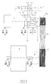
- a drive device essentially comprises a drive means 1, a pump distributor gear 4, a clutch 4a, at least one hydraulic pump 5, a fluid coupling 6, and a wedge disk 7a. Also, the drive means may comprise a further clutch 4b.
- a working machine device essentially comprises a drive device according to the invention, as well as a working machine 9. Furthermore, the working machine device according to the invention comprises a wedge disk 7c and a corresponding belt drive 7b for connection to the wedge disk 7a of the drive device.
- the drive devices described above are usually carried out with a diesel engine or with an electric motor. But also more drive means are possible. The following description is based on the example "Diesel engine as drive means" (see FIG. 1 ).
- the pump distributor gear 4 is flanged.
- the diesel engine 1 is mounted, for example, on the frame of a mobile construction machine (not shown) with corresponding fastening elements 2a / 2b.
- the pump distributor gear 4 can also be fastened to the frame of the construction machine with corresponding fastening elements 2c.
- the pump distributor gear has a housing 12.
- a flexible coupling 3 can be flanged, which in turn is arranged on a transmission input shaft 10 of the pump distributor 4.
- the elastic coupling 3 once has the function of a "damping clutch” and once that of a "compensating clutch".
- the torque flow between the transmission input shaft 10 and a transmission output shaft 11 of the pump distributor gear 4 is to be interrupted or connected with a shiftable clutch 4a.
- the actuation of the switchable couplings 4a / 4b to 4i is not relevant to the function here and can therefore be chosen arbitrarily.
- Common types of operation are hydraulic or pneumatic pressure, electromagnetic force, spring force, mechanical operations, etc.
- the following descriptions refer to couplings that are actuated by hydraulic pressure.
- the transmission input shaft 10 and the transmission output shaft 11 are mounted with bearings in the housing 12 of the pump distributor gear 4.
- On the transmission output shaft 11 of the pump distributor gear 4 is a working according to the "Föttinger principle" fluid coupling 6, also called hydrodynamic coupling (eg, with constant oil filling) plugged.
- the gearbox output torque of the pump distributor gear 4 is thus at the same time the drive torque of the fluid coupling 6.
- the fluid coupling allows the following inertia and possible load moments, which high loads for switchable Couplings mean, for all components, such as the friction elements of the switchable clutch, all torque-transmitting components and connections such as: shafts, gears, feather key connections, screw, clamping set connections, splines, are gently accelerated.
- the wedge plate 7a On the output side of the fluid coupling 6, the wedge plate 7a is attached.
- This wedge disk 7a is spatially seen in the first preferred embodiment of the invention shown here between the pump distributor gear 4 and the fluid coupling 6 and is mounted on the housing 12 of the pump distributor gear 4 via bearings.
- the belt drive 7b can now, as exemplified in FIG. 1 shown, a work machine, such as crusher 9, drive via a second wedge disk 7c.
- flat belts are also considered instead of the V-belts.
- a start-up process with the previously outlined drive device or work machine device can be designed as follows.
- the components used have the following state.
- the diesel engine 1 is not started, the clutch 4a, in particular the switchable Friction clutch 4a, is open, ie without pressure and the torque flow between the transmission input 10 and transmission output 11 is thus interrupted, the machine is preferably load torque-free (in the example described, the crusher 9 is empty) and also the optional, switchable clutches 4b to 4i can be opened ,
- the diesel engine 1 is now started first. Then it is raised to the switch-on speed (eg idle speed, "increased" idle speed, oa) of the switchable clutch 4a.
- the shiftable friction clutch 4a is turned on, that is, the clutch 4a is subjected to hydraulic pressure and the torque transmission between the transmission input shaft 10 and the transmission output shaft 11 is thus produced.
- the unit pump distributor gear 4 and switchable couplings 4a / 4b to 4i is a self-sufficient assembly.
- individual, several or all of the optional switchable clutches 4b to 4i can be switched on in order to drive the hydraulic pump (s) 5 / 5a to 5i).
- the pressure level can now be increased to eg the operating pressure.
- the height of the transmittable torque of the shiftable friction clutch 4a is adjustable.
- the diesel engine 1 can be brought to a higher speed level, eg operating speed.
- the following inertia and possible load moments which mean high loads for switchable clutches, are now gently accelerated for all components.
- the previously described unit is part of a modular system; ie in drive devices in which lower load conditions (lower mass moments of inertia to be accelerated, no or only small load moments, etc.) occur, it is also possible to accomplish the startup process only via the shiftable friction clutch 4a.
- the fluid coupling 6 can be omitted from the unit and the transmission output shaft is connected via adapter flanges directly to the wedge disk 7a.
- the kit offers the use or the waiver of an elastic coupling 3 and / or the switchable clutches 4b to 4i for switching on or off of the hydraulic pump (s).
- a further embodiment of the drive device according to the invention or the working machine device according to the invention is in the Fig. 2 shown.
- the drive device according to Fig. 2 differs from the drive device according to Fig. 1 in that the wedge disk 7a is not arranged between the shifting clutch 4a or the outgoing shaft 11 of the shifting clutch 4a and the fluid coupling 6, but the wedge disc 7a is deposited directly on the fluid coupling 6.
- the output side of the fluid coupling 6 consists of a wedge disk 7 a which is mounted on a hollow shaft of the fluid coupling 6.
- a further embodiment of the drive device according to the invention or the working machine device according to the invention is in the Fig. 3 shown.
- the drive device according to Fig. 3 differs from the drive device according to Fig. 1 and Fig. 2 in that the main drive is no longer guided directly through the pump distributor gearbox 4, but experiences a misalignment with the driving machine via a gear stage (1, 2 or multi-stage with i equal to 1 or i not equal to 1).
- This can analogously to the embodiment according to Fig. 2 , as shown, but also analogous to Fig. 1 , that is, with the arrangement of the wedge disk 7a proposed there, be implemented.
- one of the intermediate shafts could be used to drive a hydraulic pump.
- a reverse operation could be achieved via a further clutch.
Landscapes
- Engineering & Computer Science (AREA)
- Food Science & Technology (AREA)
- Arrangement Of Transmissions (AREA)
- Rotary Pumps (AREA)
Description
Die vorliegende Erfindung betrifft eine Antriebseinrichtung gemäß dem Oberbegriff des Anspruchs 1 , sowie eine Arbeitsmaschineneinrichtung gemäß dem Oberbegriff des Anspruchs 12.The present invention relates to a drive device according to the preamble of claim 1, as well as a working machine device according to the preamble of
Die
Bei Antriebseinrichtungen für schwere Lasten, beispielsweise bei Antriebseinrichtungen für Baumaschinen, sind Pumpenverteilergetriebe vorgesehen, die sowohl mindestens eine Hydraulikpumpe, als auch mindestens eine Arbeitsmaschine, wie beispielsweise einen Brecher, antreiben. Die Hydraulikpumpe wiederum treibt beispielsweise einen Hydraulikmotor an, der beispielsweise das Fahrwerk der Baumschiene antreibt. Die Arbeitsmaschine wird in der Regel über eine Keilscheibe und einen entsprechenden Riementrieb angetrieben, wobei zwischen dem Abtrieb des Pumpenverteilergetriebes und der Keilscheibe eine Strömungskupplung zwischengeschaltet ist.In drive devices for heavy loads, for example in drive equipment for construction machinery, pump transfer cases are provided, both at least one hydraulic pump, and at least one working machine, such as a crusher, drive. The hydraulic pump in turn drives, for example, a hydraulic motor, which drives, for example, the chassis of the tree rail. The work machine is usually driven by a wedge disk and a corresponding belt drive, wherein between the output of the pump distributor gear and the wedge disk, a fluid coupling is interposed.
Insbesondere im Zusammenhang mit Betriebsstörungen, wie beispielsweise einem unvorhergesehenem abrupten Stoppen der Arbeitsmaschine, beispielsweise einem Klemmen des Brechers, entsteht eine hohe Belastung für die Strömungskupplung und auch die vor- und nachgeschalteten Komponenten. Grundsätzlich kann für diesen Fall das Fluid aus der Strömungskupplung abgelassen werden, wodurch die Belastung zunächst zurückgeht. Andererseits nimmt dieser Vorgang einige Zeit in Anspruch.In particular, in connection with malfunction, such as an unforeseen abrupt stop the machine, such as a jamming of the crusher, creates a high load on the fluid coupling and the upstream and downstream components. In principle, the fluid can be drained from the fluid coupling for this case, whereby the load initially decreases. On the other hand, this process takes some time.
Die Aufgabe der vorliegenden Erfindung bestand somit darin, die Belastungen für die Antriebseinrichtung im Störfall zu reduzieren.The object of the present invention was therefore to reduce the burden on the drive device in case of failure.
Erfindungsgemäß wird diese Aufgabe durch eine Antriebseinrichtung mit den kennzeichnenden Merkmalen des Anspruchs 1 gelöst. Über diese Schaltkupplung kann die Strömungskupplung und die nachgeschaltete Keilscheibe und die ggf. nachgeschaltete Arbeitsmaschine mit einem Drehmoment beaufschlagt werden bzw. der Drehmomentverlauf unterbrochen werden. Hierdurch kann auf einen Störfall viel schneller reagiert und der Drehmomentfluss zwischen Pumpenverteilergetriebe und Keilscheibe bzw. nachgeschalteter Arbeitsmaschine durch die Schaltkupplung rasch unterbrochen werden. Durch entsprechende Ausgestaltung der Schaltkupplung, beispielsweise als Reibkupplung, kann die Drehmomentübertragung für die nachgeschalteten Komponenten beispielsweise auch langsam hochgefahren werden, so dass sich über die Schaltkupplung ein vorbestimmter Anfahrvorgang darstellen lässt, wodurch beispielsweise ein schonendes Anfahren realisiert und die Lebensdauer der Antriebseinrichtung erhöht werden kann.According to the invention this object is achieved by a drive device with the characterizing features of claim 1. About this clutch, the fluid coupling and the Downstream wedge disk and possibly downstream machine are subjected to a torque or the torque curve are interrupted. As a result, reacts much faster to a fault and the torque flow between the pump distributor gear and wedge disk or downstream machine can be interrupted quickly by the clutch. By appropriate design of the clutch, for example as a friction clutch, the torque transmission for the downstream components, for example, can be ramped up slowly, so that can represent a predetermined starting over the clutch, whereby, for example, a gentle start-up realized and the life of the drive device can be increased.
Weitere vorteilhafte Ausgestaltungen der vorgeschlagene Erfindung ergeben sich insbesondere aus den Unteransprüchen. Die Merkmale der Unteransprüche können grundsätzlich beliebig miteinander kombiniert werden.Further advantageous embodiments of the proposed invention will become apparent in particular from the dependent claims. The features of the subclaims can basically be combined with each other arbitrarily.
In einer weiteren vorteilhaften Ausgestaltung der erfindungsgemäßen Antriebseinrichtung kann vorgesehen sein, dass die Hydraulikpumpe über eine Schaltkupplung zur Übertragung einer Drehbewegung bzw. eines Drehmomentes mit dem Pumpenverteilergetriebe verbunden ist. Die Hydraulikpumpe kann beispielsweise zum Antrieb eines Hydraulikmotors eingesetzt werden. Der Hydraulikmotor kann beispielsweise zum Antrieb von Rädern oder Raupenkette einer Baumaschine eingesetzt werden. Mit der Schaltkupplung kann die Hydraulikpumpe wahlweise zu- bzw. abgeschaltet werden, um beispielsweise die Leerlaufverluste der Hydraulikpumpen während des eigentlichen Arbeitsvorgangs "Brechen" zu vermeiden. Dadurch sinkt der Energieverbrauch der gesamten Antriebseinrichtung.In a further advantageous embodiment of the drive device according to the invention can be provided that the hydraulic pump is connected via a clutch for transmitting a rotational movement or torque with the pump distributor gearbox. The hydraulic pump can be used, for example, to drive a hydraulic motor. The hydraulic motor can be used for example for driving wheels or track of a construction machine. With the clutch, the hydraulic pump can optionally be switched on and off, for example, to avoid the idling losses of the hydraulic pumps during the actual operation "breaking". This reduces the energy consumption of the entire drive device.
In einer weiteren vorteilhaften Ausgestaltung der erfindungsgemäßen Antriebseinrichtung kann vorgesehen sein, dass das Antriebsmittel über eine elastische Kupplung mit dem Pumpenverteilergetriebe verbunden ist. Die elastische Kupplung kann einmal die Funktion einer "Dämpfungskupplung" und einmal die einer "Ausgleichskupplung" haben. Vorteilhafterweise können mit der elastische Kupplung Schwingungen in Umfangsrichtung (= Drehmomentspitzen) gedämpft und Ausrichtungsfehler zwischen Antriebsmittel und Pumpenverteilergetriebe ausgeglichen werden.In a further advantageous embodiment of the drive device according to the invention can be provided that the drive means is connected via a flexible coupling with the pump distributor gearbox. The elastic coupling can once have the function of a "damping clutch" and once that of a "compensating clutch". Advantageously, with the elastic coupling vibrations in the circumferential direction (= torque peaks) attenuated and alignment errors between the drive means and pump distributor gearbox can be compensated.
In einer weiteren vorteilhaften Ausgestaltung der erfindungsgemäßen Antriebseinrichtung kann vorgesehen sein, dass mindestens eine weitere Hydraulikpumpe über eine zugeordnete Schaltkupplung mit dem Pumpenverteilergetriebe verbunden ist. Hierdurch kann die Energiebilanz der Antriebseinrichtung optimiert werden, da die aktuell nicht benötigten Hydraulikpumpen abgeschaltet werden können und somit keine Verlustleistungen produzieren.In a further advantageous embodiment of the drive device according to the invention can be provided that at least one further hydraulic pump is connected via an associated clutch with the pump distributor gearbox. As a result, the energy balance of the drive device can be optimized because the currently not required hydraulic pumps can be switched off and thus produce no power losses.
In einer weiteren vorteilhaften Ausgestaltung der erfindungsgemäßen Antriebseinrichtung kann vorgesehen sein, dass die Keilscheibe zwischen der Schaltkupplung und der Strömungskupplung angeordnet ist, wobei die Keilscheibe über Lager auf dem Gehäuse des Pumpenverteilergetriebes abgelagert ist. Dies hat den Vorteil, dass die Radialkräfte des Riementriebs über die Lager der Keilscheibe von dem stehenden Gehäuse des Pumpenverteilergetriebes aufgenommen werden können.In a further advantageous embodiment of the drive device according to the invention can be provided that the wedge disk between the clutch and the fluid coupling is arranged, wherein the wedge disk is deposited on bearings on the housing of the pump distributor gear. This has the advantage that the radial forces of the belt drive can be absorbed by the bearings of the wedge disk of the stationary housing of the pump distributor gearbox.
In einer weiteren vorteilhaften Ausgestaltung der erfindungsgemäßen Antriebseinrichtung kann vorgesehen sein, dass das Pumpenverteilergetriebe eine Getriebestufe, insbesondere eine ein oder mehrstufige Getriebestufe mit einer Übersetzung i gleich 1 oder i ungleich 1 umfasst. Hierdurch kann sich ein Achseversatz zwischen der Antriebsachse des Pumpenverteilergetriebes und der Achse der Keilscheibe geschaffen werden. Ferner können durch die Getriebestufe folgende weitere Vorteile erreicht werden. Der axiale Einbauraum kann verkürzt werden. Eine Variation der Drehzahlen für die Keilscheibe bzw. die Hydraulikpumpe(n) bei entsprechenden Übersetzungen der Getriebestufe ist möglich. Auch ist bei ungerader Getriebestufenanzahl auch eine Drehrichtungsumkehr möglich.In a further advantageous embodiment of the drive device according to the invention it can be provided that the pump distributor gearbox comprises a gear stage, in particular a one-stage or multi-stage gear stage with a ratio i equal to 1 or i not equal to 1. This can cause an axis offset between the drive axis of the pump distributor gear and the axis of the wedge disk are created. Furthermore, the following additional advantages can be achieved by the gear stage. The axial installation space can be shortened. A variation of the speeds for the wedge disk or the hydraulic pump (s) with corresponding ratios of the gear stage is possible. Also, a reverse rotation is possible with odd gear stage number.
In einer weiteren vorteilhaften Ausgestaltung der erfindungsgemäßen Antriebseinrichtung kann vorgesehen sein, dass es sich bei der Strömungskupplung um eine nach dem Föttingerprinzip arbeitende hydrodynamische Kupplung handelt. Bei Strömungskupplungen nach dem Föttingerprinzip sind die Kupplungsteile der An- und Abtriebsseite mechanisch nicht miteinander verbunden. Vielmehr dient insbesondere ein Fluid als Drehmomentübertragungsmittel. Somit arbeitet die Kupplung verschleißfrei und begrenzt das Anfahr- und Maximaldrehmoment im Antriebsstrang. Des weiteren dient sie als Anlaufhilfe für den Motor, als Überlastschutz im Störfall und zur Drehschwingungstrennung.In a further advantageous embodiment of the drive device according to the invention, it may be provided that the fluid coupling is a hydrodynamic coupling operating according to the Föttinger principle. In fluid couplings according to the Föttinger principle, the coupling parts of the input and output side are not mechanically connected to each other. Rather, in particular a fluid serves as a torque transmitting means. Thus, the clutch works wear-free and limits the starting and maximum torque in the drive train. Furthermore, it serves as a start-up aid for the engine, as overload protection in case of failure and for torsional vibration separation.
In einer weiteren vorteilhaften Ausgestaltung der erfindungsgemäßen Antriebseinrichtung kann vorgesehen sein, dass die Schaltkupplung für die Keilscheibe im Gehäuse des Pumpenverteilergetriebes aufgenommen ist. Durch die Unterbringung der Schaltkupplung in dem Gehäuse des Pumpenverteilergetriebes kann eine kompakte Antriebseinrichtung bereitgestellt werden. Im Getriebe wird vorzugsweise eine Reibungskupplung mit für "Nasslauf" geeigneten Belägen eingesetzt werden. Nasslaufende Lamellenkupplungen z.B. bauen bei gleicher Leistungsübertragung wesentlich kleiner als trockenlaufende Reibungskupplungen. Nasslaufende Beläge sind bei dynamischen Beschleunigungsvorgängen bei entsprechender Belastung / Auslegung verschleißfrei, während trockenlaufende Beläge immer Verschleißbehaftet sind.In a further advantageous embodiment of the drive device according to the invention can be provided that the clutch for the wedge plate is received in the housing of the pump distributor gearbox. By housing the clutch in the housing of the pump distributor, a compact drive means can be provided. In the transmission, a friction clutch with suitable for "wet run" coverings is preferably used. Wet-running multi-plate clutches, for example, build much smaller than dry friction clutches with the same power transmission. Wet running linings are considered as appropriate during dynamic acceleration processes Wear / design wear-free, while dry running pads are always subject to wear.
Eine weitere Aufgabe der vorliegenden Erfindung hat darin gelegen, eine verbesserte Arbeitsmaschineneinrichtung vorzuschlagen, insbesondere eine Arbeitsmaschineneinrichtung vorzuschlagen, deren Belastungen für die Arbeitsmaschineneinrichtung im Störfall reduziert werden kann.Another object of the present invention has been to propose an improved working machine device, in particular to propose a working machine device whose loads can be reduced for the working machine device in case of failure.
Erfindungsgemäß wird diese Aufgabe durch eine Arbeitsmaschineneinrichtung mit den kennzeichnenden Merkmalen des Anspruchs 12. Dadurch, dass es sich bei der Antriebseinrichtung der Arbeitsmaschineneinrichtung um einen Antriebseinrichtung gemäß mindestens einem der Ansprüche 1 bis 11 handelt, können die Vorteile der erfindungsgemäßen Antriebseinrichtung für die erfindungsgemäße Arbeitsmaschineneinrichtung genutzt werden, sprich die Belastung der Arbeitsmaschineneinrichtung können für den Störfall reduziert werden, da der Drehmomentfluss durch die Schaltkupplung rasch unterbrochen werden kann. Da sich über die Schaltkupplung ein vorbestimmter Anfahrvorgang darstellen lässt, kann beispielsweise ebenfalls ein schonendes Anfahren der Arbeitsmaschineneinrichtung realisieren und deren Lebensdauer verlängert werden.According to the invention, this object is achieved by a working machine device having the characterizing features of
Weitere vorteilhafte Ausgestaltungen der vorgeschlagene Erfindung ergeben sich insbesondere aus den Unteransprüchen. Die Merkmale der Unteransprüche können grundsätzlich beliebig miteinander kombiniert werden.Further advantageous embodiments of the proposed invention will become apparent in particular from the dependent claims. The features of the subclaims can basically be combined with each other arbitrarily.
Weitere Merkmale und Vorteile der vorliegenden Erfindung werden deutlich anhand der nachfolgenden Beschreibung bevorzugter Ausführungsbeispiele unter Bezugnahme auf die beiliegenden Abbildungen. Darin zeigen
- Fig. 1
- eine erfindungsgemäße Antriebseinrichtung und eine erfindungsgemäße Arbeitsmaschineneinrichtung in einer ersten Ausführungsform;
- Fig. 2
- eine erfindungsgemäße Antriebseinrichtung und eine erfindungsgemäße Arbeitsmaschineneinrichtung in einer zweiten Ausführungsform;
- Fig. 3
- eine erfindungsgemäße Antriebseinrichtung und eine erfindungsgemäße Arbeitsmaschineneinrichtung in einer dritten Ausführungsform.
- Fig. 1
- a drive device according to the invention and a work machine device according to the invention in a first embodiment;
- Fig. 2
- a drive device according to the invention and a work machine device according to the invention in a second embodiment;
- Fig. 3
- a drive device according to the invention and a working machine device according to the invention in a third embodiment.
Folgende Bezugszeichen werden in den Abbildungen verwendet:
- 1
- Antriebsmittel / Dieselmotor
- 1a
- Motorschwungrad
- 1b
- Anschlussgehäuse
- 2a
- Befestigungselement
- 2b
- Befestigungselement
- 2c
- Befestigungselement
- 3
- elastische Kupplung
- 4
- Pumpenverteilergetriebe
- 4a
- Schaltkupplung
- 4b
- Schaltkupplung
- 4i
- weitere Schaltkupplung
- 5
- Hydraulikpumpe
- 5a
- Hydraulikpumpe
- 5b
- Hydraulikpumpe
- 5i
- weitere Hydraulikpumpe
- 6
- Strömungskupplung
- 7a
- Keilscheibe
- 7b
- Riementrieb
- 7c
- Keilscheibe
- 8
- weitere Komponenten, wie z.B. Wellen, Kardanwellen, Wellenkupplungen, Getriebe, Zahnkupplungen, usw.
- 9
- Arbeitsmaschine
- 10
- Getriebeeingangswelle
- 11
- Getriebeabgangswelle
- 12
- Gehäuse
- 1
- Drive means / diesel engine
- 1a
- flywheel
- 1b
- connection housing
- 2a
- fastener
- 2 B
- fastener
- 2c
- fastener
- 3
- elastic coupling
- 4
- Splitterbox
- 4a
- clutch
- 4b
- clutch
- 4i
- further clutch
- 5
- hydraulic pump
- 5a
- hydraulic pump
- 5b
- hydraulic pump
- 5i
- further hydraulic pump
- 6
- fluid coupling
- 7a
- wedge disk
- 7b
- belt drive
- 7c
- wedge disk
- 8th
- other components, such as shafts, cardan shafts, shaft couplings, gears, gear couplings, etc.
- 9
- working machine
- 10
- Transmission input shaft
- 11
- Gear shaft
- 12
- casing
Zunächst wird auf
Eine erfindungsgemäße Antriebseinrichtung umfasst im Wesentlichen ein Antriebsmittel 1 , ein Pumpenverteilergetriebe 4, eine Schaltkupplung 4a, mindestens eine Hydraulikpumpe 5, eine Strömungskupplung 6, sowie eine Keilscheibe 7a. Auch kann die Antriebseinrichtung eine weitere Schaltkupplung 4b umfassen.A drive device according to the invention essentially comprises a drive means 1, a pump distributor gear 4, a clutch 4a, at least one
Eine erfindungsgemäße Arbeitsmaschineneinrichtung umfasst im Wesentlichen eine erfindungsgemäße Antriebseinrichtung, sowie eine Arbeitsmaschine 9. Ferner umfasst die erfindungsgemäße Arbeitsmaschineneinrichtung eine Keilscheibe 7c und einen entsprechenden Riementrieb 7b zur Verbindung mit der Keilscheibe 7a der Antriebseinrichtung.A working machine device according to the invention essentially comprises a drive device according to the invention, as well as a working
Um den Anlaufvorgang bei Antriebseinrichtungen, bei denen hohe Anforderungen (z.B.: große zu beschleunigende Massenträgheiten, lange Rutschzeiten, hohe Lastmomente, usw.) an reibschlüssige Schaltkupplungen gestellt werden (so genannte "Schweranläufe"), für die verwendeten Komponenten ohne steuerungstechnische Maßnahmen sicherer zu machen, ist das folgend beschriebene Antriebskonzept erarbeitet worden.To the startup process in drive systems where high demands (eg: large inertia to be accelerated, long slipping, high load torque, etc.) to frictional clutches are made (so-called "heavy starts"), for the components used without control technology To make measures more secure, the drive concept described below has been developed.
Die oben beschriebenen Antriebseinrichtungen werden in der Regel mit einem Dieselmotor oder mit einen E-Motor ausgeführt. Aber auch weitere Antriebsmittel sind möglich. Die folgende Beschreibung erfolgt am Beispiel "Dieselmotor als Antriebsmittel" (siehe
Ferner wird nachfolgend beispielhaft von einer mobilen Baumaschine als Arbeitsmaschineneinrichtung bzw. Brecher als Arbeitsmaschine ausgegangen, ohne dass dies als Einschränkung der Erfindung verstanden werden soll.Furthermore, the following is an example of a mobile construction machine as a working machine device or crusher as a working machine, without this being to be understood as a limitation of the invention.
Direkt an einem Anschlussgehäuse 1 b des Dieselmotors 1 wird das Pumpenverteilergetriebe 4 angeflanscht. Der Dieselmotor 1 ist z.B. auf den Rahmen einer mobilen Baumaschine (nicht dargestellt) mit entsprechenden Befestigungselementen 2a / 2b befestigt. Optional kann das Pumpenverteilergetriebe 4 ebenfalls mit entsprechenden Befestigungselementen 2c an den Rahmen der Baumaschine befestigt werden. Das Pumpenverteilergetriebe weist ein Gehäuse 12 auf. An einem Motorschwungrad 1a kann eine elastische Kupplung 3 angeflanscht werden, die wiederum auf einer Getriebeeingangswelle 10 des Pumpenverteilergetriebes 4 angeordnet ist. Die elastische Kupplung 3 hat einmal die Funktion einer "Dämpfungskupplung" und einmal die einer "Ausgleichskupplung". Somit sind deren Aufgaben, Schwingungen in Umfangsrichtung (= Drehmomentspitzen) zu dämpfen und Ausrichtungsfehler zwischen Dieselmotor 1 und Pumpenverteilergetriebe 4 auszugleichen. Auf der Getriebeeingangswelle 10 des Pumpenverteilergetriebes 4 befindet sich das antreibende Zahnrad für den "Pumpenstrang" / die "Pumpenstränge". Die Anzahl und der Typ der Hydraulikpumpe(n) 5 / 5a bis 5i und deren Anschlussgeometrien ist anwendungsspezifisch und kann somit stark variieren. Erfindungsgemäß ist vorgesehen, dass diese Pumpenstränge mit Hilfe von schaltbaren Kupplungen 4b bis 4i, die innerhalb oder auch außerhalb des Pumpenverteilergetriebes 4 angeordnet sein können, zu- bzw. wegzuschalten.Directly to a
Hierdurch kann die Energiebilanz der Maschine optimiert werden, da die aktuell nicht benötigten Hydraulikpumpen abgeschaltet werden können und somit keine Verlustleistungen produzieren. Der Drehmomentenfluß zwischen der Getriebeeingangswelle 10 und einer Getriebeabgangswelle 11 des Pumpenverteilergetriebes 4 ist mit einer schaltbaren Kupplung 4a zu unterbrechen bzw. miteinander zu verbinden.As a result, the energy balance of the machine can be optimized because the currently not required hydraulic pumps can be switched off and thus produce no power losses. The torque flow between the
Die Betätigungsart der schaltbaren Kupplungen 4a / 4b bis 4i ist hier für die Funktion nicht relevant und kann somit beliebig gewählt werden. Häufige Betätigungsarten sind hydraulischer oder pneumatischer Druck, elektromagnetische Kraft, Federkraft, mechanische Betätigungen usw. Die folgenden Beschreibungen beziehen sich auf Kupplungen, die über hydraulischen Druck betätigt werden.The actuation of the switchable couplings 4a / 4b to 4i is not relevant to the function here and can therefore be chosen arbitrarily. Common types of operation are hydraulic or pneumatic pressure, electromagnetic force, spring force, mechanical operations, etc. The following descriptions refer to couplings that are actuated by hydraulic pressure.
Die Getriebeeingangswelle 10 als auch die Getriebeabgangswelle 11 sind mit Lagern in dem Gehäuse 12 des Pumpenverteilergetriebes 4 gelagert. Auf der Getriebeabgangswelle 11 des Pumpenverteilergetriebes 4 ist eine nach dem "Föttingerprinzip" arbeitende Strömungskupplung 6, auch hydrodynamische Kupplung (z.B. mit konstanter Ölfüllung) genannt, aufgesteckt. Das Getriebeabtriebsmoment des Pumpenverteilergetriebes 4 ist somit zugleich das Antriebsmoment der Strömungskupplung 6. Durch die Strömungskupplung können die nachfolgenden Massenträgheiten und eventuelle Lastmomente, welche hohe Belastungen für schaltbare Kupplungen bedeuten, für alle Komponenten, wie beispielsweise die Reibelemente der schaltbaren Kupplung, alle drehmomentübertragenden Bauteile und Verbindungen wie z.B.: Wellen, Zahnräder, Passfederverbindungen, Schraubverbindungen, Spannsatzverbindungen, Steckverzahnungen, schonend beschleunigt werden.The
An der Abtriebsseite der Strömungskupplung 6 ist die Keilscheibe 7a befestigt. Diese Keilscheibe 7a befindet sich in der hier zunächst dargestellten bevorzugten ersten Ausführungsform der Erfindung räumlich gesehen zwischen dem Pumpenverteilergetriebe 4 und der Strömungskupplung 6 und ist über Lager auf dem Gehäuse 12 des Pumpenverteilergetriebes 4 abgelagert. Dies hat den Vorteil, dass die Radialkräfte des Riementriebs 7b über die Lager der Keilscheibe 7a von dem stehenden Gehäuse des Pumpenverteilergetriebes 4 aufgenommen werden. Der Riementrieb 7b kann nun, wie beispielhaft in
Ein Anlaufvorgang mit der zuvor skizzierten Antriebseinrichtung bzw. Arbeitsmaschineneinrichtung kann sich wie folgt gestalten.A start-up process with the previously outlined drive device or work machine device can be designed as follows.
Im Ruhezustand der Antriebseinrichtung haben die verwendeten Komponenten folgenden Zustand. Der Dieselmotor 1 ist nicht gestartet, die Schaltkupplung 4a, insbesondere die schaltbare Reibungskupplung 4a, ist geöffnet, d.h. drucklos und der Drehmomentfluss zwischen Getriebeeingang 10 und Getriebeausgang 11 ist somit unterbrochen, die Arbeitsmaschine ist vorzugsweise lastmomentfrei (im beschriebenen Beispiel ist somit der Brecher 9 leer) und auch die optionalen, schaltbaren Kupplungen 4b bis 4i können geöffnet sein. Um die Antriebseinrichtung aus dem Ruhezustand in den Betriebszustand zu überführen, wird nun als erstes der Dieselmotor 1 gestartet. Anschließend wird er auf die Einschaltdrehzahl (z.B. Leerlaufdrehzahl, "erhöhte" Leerlaufdrehzahl, o.a.) der schaltbaren Kupplung 4a hochgefahren. In diesem Zustand wird die schaltbare Reibungskupplung 4a eingeschaltet, d.h. die Kupplung 4a wird mit hydraulischen Druck beaufschlagt und die Drehmomentübertragung zwischen Getriebeeingangswelle 10 und Getriebeabgangswelle 11 ist somit hergestellt. Im Falle von hydraulisch betätigten Kupplungen kann die Versorgung der schaltbaren Kupplung 4a, aber auch die der optionalen Schaltkupplungen 4b bis 4i, mit Schalt- und / oder auch Kühlöl vorzugsweise mit Hydraulikpumpen erfolgen, die an dem Pumpenverteilergetriebe 4 befestigt sind. Somit ist die Einheit Pumpenverteilergetriebe 4 und schaltbare Kupplungen 4a / 4b bis 4i eine autarke Baugruppe. Vorher, in diesem Zustand oder auch nachher können einzelne, mehrere oder alle der optionalen, schaltbaren Kupplungen 4b bis 4i zugeschaltet werden um die Hydraulikpumpe(n) 5 / 5a bis 5i) anzutreiben. Bei Betätigung der schaltbaren Reibungskupplung 4a werden nur die Massenträgheiten zwischen dem Abtrieb der schaltbaren Reibungskupplung 4a bis zu der Strömungskupplung 6 selber auf die (Einschalt-) Drehzahl des Dieselmotors 1 beschleunigt. Eine zusätzliche Belastung für die schaltbare Reibungskupplung 4a ergibt sich aus der Kupplungskennlinie der Strömungskupplung 6, die wiederum abhängig ist von der jeweiligen Ausführung (z.B. Strömungskupplungen ohne oder mit Verzögerungskammer, mit großer Verzögerungskammer, mit fliehkraftbetätigten Ventilen, usw.) der Strömungskupplung 6. Die Betätigung der schaltbaren Reibungskupplung 4a während der Synchronisation (= Beschleunigungsvorgang) kann z.B. auf einem niedrigeren Druckniveau (z.B. Einschaltdruck) erfolgen. Nachdem die schaltbare Reibungskupplung 4a synchronisiert hat, kann nun das Druckniveau auf z.B. den Betriebsdruck erhöht werden. Somit ist über die Höhe des hydraulischen Druck die Höhe des übertragbaren Drehmoments der schaltbaren Reibungskupplung 4a einstellbar. Jetzt kann der Dieselmotor 1 auf ein höheres Drehzahlniveau, z.B. Betriebsdrehzahl, gebracht werden. Abhängig von der Kupplungskennlinie der Strömungskupplung 6 werden nun die nachfolgenden Massenträgheiten und eventuelle Lastmomente, welche hohe Belastungen für schaltbare Kupplungen bedeuten, für alle Komponenten schonend beschleunigt.When the drive device is at rest, the components used have the following state. The diesel engine 1 is not started, the clutch 4a, in particular the switchable Friction clutch 4a, is open, ie without pressure and the torque flow between the
Aus dieser Verknüpfung der Einzelkomponenten (elastische Kupplung 3) (optional), Pumpenverteilergetriebe 4 mit schaltbarer Kupplung 4a, schaltbare Kupplung(en) 4b bis 4i (optional), Strömungskupplung 6 mit konstanter Ölfüllung die nach dem Föttingerprinzip arbeitet und eine gelagerte Keilscheibe 7a ist eine Einheit entwickelt worden, mit denen Arbeitsmaschinen zu- und auch abschaltbar angetrieben werden können. Im Falle einer Blockade der Arbeitsmaschine 9 kann durch die schaltbare Kupplung 4a der nachfolgende Antriebsstrang von dem leistungsstarken, antreibenden Dieselmotor 1 schnell getrennt werden. Andernfalls würde der Dieselmotor gegen den blockierten Brecher arbeiten, wodurch wiederum hohe Belastungen für alle Komponenten entstehen. Die Einheit kann durch die Auswahl der Einzelkomponenten und deren Betätigung so abgestimmt werden, dass jede Einzelkomponente nur gering belastet wird und somit eine lange, sichere und wirtschaftliche Lebensdauer für sie zu erwarten ist. Die bisher geschilderte Einheit ist Bestandteil eines Baukastensystems; d.h. bei Antriebseinrichtungen bei denen niedrigere Belastungszustände (geringere zu beschleunigende Massenträgheitsmomente, keine oder nur geringe Lastmomente, usw.) vorkommen, ist es auch möglich den Anlaufvorgang nur über die schaltbare Reibungskupplung 4a zu bewerkstelligen. In diesem Fall kann die Strömungskupplung 6 aus der Einheit entfallen und die Getriebeabgangswelle wird über Adapterflansche direkt mit der Keilscheibe 7a verbunden. Auch bietet der Baukasten den Einsatz oder den Verzicht auf eine elastische Kupplung 3 und / oder der schaltbaren Kupplungen 4b bis 4i zum zu- oder abschalten der Hydraulikpumpe(n).From this combination of the individual components (elastic coupling 3) (optional), pump distributor gear 4 with switchable coupling 4a, switchable coupling (s) 4b to 4i (optional),
Eine weitere Ausführungsform der erfindungsgemäßen Antriebseinrichtung bzw. der erfindungsgemäßen Arbeitsmaschineneinrichtung ist in der
Im Wesentlichen kann auf die obigen Ausführungen verwiesen werden. Die Antriebseinrichtung gemäß
Der Vorteil dieser Anordnung liegt darin, dass der "Riementrieb" von einer Seite frei zugänglich ist; d.h. bei der Montage bzw. Demontage der Riemen auf die Keilscheiben brauchen diese nicht über die Strömungskupplung geführt werden.The advantage of this arrangement is that the "belt drive" is freely accessible from one side; ie during assembly or disassembly of the belt on the wedge discs they do not need to be guided through the fluid coupling.
Eine weitere Ausführungsform der erfindungsgemäßen Antriebseinrichtung bzw. der erfindungsgemäßen Arbeitsmaschineneinrichtung ist in der
Diese Ausführungsform zeichnet sich durch folgende Vorteile aus:
- Verkürzung des axialen Einbauraums
- Mögliche Variation der Drehzahl im Hauptantriebsstrang bei entsprechenden Übersetzungen der Getriebestufe
- Mögliche Drehrichtungsumkehr bei ungerader Getriebestufenanzahl
- Shortening of the axial installation space
- Possible variation of the speed in the main drive train with corresponding gear ratios
- Possible direction of rotation reversal with odd number of gears
Claims (14)
- Drive device for a work machine device, comprising at least- one drive means (1), one power take-off gear for pumps (4), one hydraulic pump (5), one flow coupling (6) and one V-pulley (7a),- the drive means (1) driving the power take-off gear for pumps (4),- the power take-off gear for pumps (4) driving the at least one hydraulic pump (5),- the power take-off gear for pumps (4) driving the V-pulley (7a) via the flow coupling (6),characterized in that- a shift clutch (4a) actuable during operation is interposed between the power take-off gear for pumps (4) and V-pulley (7a).
- Drive device according to Claim 1, characterized in that the flow coupling (6) is preceded by the shift clutch (4a).
- Drive device according to at least one of the preceding claims, characterized in that the power take-off gear for pumps has a housing (12).
- Drive device according to at least one of the preceding claims, characterized in that the hydraulic pump (5) is driven by the power take-off gear for pumps (4) via a shift clutch (4b).
- Drive device according to at least one of the preceding claims, characterized in that an elastic coupling (3) is interposed between the drive means (1) and the power take-off gear for pumps (4).
- Drive device according to at least one of the preceding claims, characterized in that at least one further hydraulic pump (5a, 5b, 5i) is connected to the power take-off gear for pumps (4) via an assigned shift clutch (4i).
- Drive device according to at least one of the preceding claims, characterized in that the V-pulley (7a) is arranged between the shift clutch (4a) and the flow coupling (6), the V-pulley (7a) being mounted on the housing (12) of the power take-off gear for pumps (4) via bearings.
- Drive device according to at least one of the preceding claims, characterized in that the V-pulley (7a) is mounted directly on the flow coupling (6).
- Drive device according to at least one of the preceding claims, characterized in that the power take-off gear for pumps comprises a gear stage, in particular a single-step or multiple-step gear stage with a ratio i equal to 1 or i unequal to 1.
- Drive device according to at least one of the preceding claims, characterized in that the flow coupling is a hydrodynamic coupling operating according to the "Föttinger principle".
- Drive device according to at least one of the preceding claims, characterized in that the shift clutch (4a) for the V-pulley (7a) is accommodated in the housing (12) of the power take-off gear for pumps (4).
- Work machine device, comprising a drive device and a work machine (9), characterized in that the said drive device is a drive device according to at least one of Claims 1 to 11.
- Work machine device according to Claim 12, characterized in that the work machine device comprises a V-pulley (7c) and a belt drive (7b), the V-pulley (7c) being set up for driving the work machine (9), and the V-pulley (7c) of the work machine (9) being connected to the V-pulley (7a) of the drive device via the belt drive (7b).
- Work machine device according to at least one of the preceding claims, characterized in that a shaft, cardan shaft, shaft coupling, gear and/or denture clutch is arranged between the V-pulley (7c) and the work machine.
Applications Claiming Priority (1)
| Application Number | Priority Date | Filing Date | Title |
|---|---|---|---|
| DE102011014530 | 2011-03-18 |
Publications (2)
| Publication Number | Publication Date |
|---|---|
| EP2500100A1 EP2500100A1 (en) | 2012-09-19 |
| EP2500100B1 true EP2500100B1 (en) | 2014-03-12 |
Family
ID=45936785
Family Applications (1)
| Application Number | Title | Priority Date | Filing Date |
|---|---|---|---|
| EP20120159842 Not-in-force EP2500100B1 (en) | 2011-03-18 | 2012-03-16 | Drive device and work machine device |
Country Status (2)
| Country | Link |
|---|---|
| EP (1) | EP2500100B1 (en) |
| ES (1) | ES2470319T3 (en) |
Cited By (2)
| Publication number | Priority date | Publication date | Assignee | Title |
|---|---|---|---|---|
| CN105833945A (en) * | 2015-02-02 | 2016-08-10 | 西门子公司 | Drive arrangement |
| CN111212689A (en) * | 2017-10-25 | 2020-05-29 | 克磊镘有限公司 | Drive system for operating a crusher and method for operating a crusher |
Families Citing this family (1)
| Publication number | Priority date | Publication date | Assignee | Title |
|---|---|---|---|---|
| DE102017220029B4 (en) * | 2017-11-10 | 2023-05-11 | Zf Friedrichshafen Ag | Method for operating a work machine with a torque measuring device |
Family Cites Families (8)
| Publication number | Priority date | Publication date | Assignee | Title |
|---|---|---|---|---|
| DE2917766A1 (en) * | 1979-04-20 | 1980-10-23 | Buehler Ag Geb | Agitator-type grinding machine - has rotor and grinder drum assembly mounted resiliently on supporting structure |
| DE9400147U1 (en) * | 1994-01-07 | 1994-03-03 | ECO Umwelttechnik Vertriebs-GmbH i.K., 87616 Marktoberdorf | Shredding device |
| SE523037C2 (en) * | 2000-11-02 | 2004-03-23 | Sandvik Ab | Methods and apparatus for crushing plant |
| US6769248B2 (en) * | 2002-06-13 | 2004-08-03 | Turbo Research, Inc. | Fluid coupling for mobile equipment |
| CN2607196Y (en) * | 2003-02-26 | 2004-03-24 | 江苏正昌集团有限公司 | Refuse crusher |
| US8376653B2 (en) * | 2007-04-23 | 2013-02-19 | Wirtgen Gmbh | Self-propelled road construction machine |
| DE502009000291D1 (en) * | 2009-05-25 | 2011-02-24 | Joseph Voegele Ag | Paver and process |
| AT508989B1 (en) * | 2009-10-29 | 2011-12-15 | Stefan Hartl | DRIVE FOR HEAVY EQUIPMENT |
-
2012
- 2012-03-16 EP EP20120159842 patent/EP2500100B1/en not_active Not-in-force
- 2012-03-16 ES ES12159842.9T patent/ES2470319T3/en active Active
Cited By (3)
| Publication number | Priority date | Publication date | Assignee | Title |
|---|---|---|---|---|
| CN105833945A (en) * | 2015-02-02 | 2016-08-10 | 西门子公司 | Drive arrangement |
| CN111212689A (en) * | 2017-10-25 | 2020-05-29 | 克磊镘有限公司 | Drive system for operating a crusher and method for operating a crusher |
| CN111212689B (en) * | 2017-10-25 | 2021-06-11 | 克磊镘有限公司 | Drive system for operating a crusher and method for operating a crusher |
Also Published As
| Publication number | Publication date |
|---|---|
| ES2470319T3 (en) | 2014-06-23 |
| EP2500100A1 (en) | 2012-09-19 |
Similar Documents
| Publication | Publication Date | Title |
|---|---|---|
| EP2655113B1 (en) | Hybrid module for a drive train of a vehicle | |
| DE102004061020B4 (en) | Torque transfer unit and drive train with this | |
| EP2718132B1 (en) | Hybrid module for a drivetrain of a vehicle | |
| EP2841203B1 (en) | Driving device and work machine device | |
| EP1275867B1 (en) | Dual clutch | |
| DE112016005787B4 (en) | Separating clutch for a motor vehicle | |
| WO2018054414A1 (en) | Multi-clutch device and hybrid module for a motor vehicle | |
| WO2017076658A1 (en) | Internal combustion engine decoupling device of a phev transmission unit | |
| EP3593002B1 (en) | Clutch device and hybrid module | |
| EP2017493A2 (en) | Construction machine, clutch and method for shifting power flow | |
| WO2017101930A1 (en) | Disconnect clutch for a motor vehicle | |
| WO2019086073A1 (en) | Multi-clutch device and hybrid module for a motor vehicle | |
| WO2023241751A1 (en) | Dry dual clutch with individually actuatable sub-clutches | |
| EP2500100B1 (en) | Drive device and work machine device | |
| DE102015118398A1 (en) | Drive device and working machine device | |
| WO2017202408A1 (en) | Clutch device and hybrid module | |
| DE102017111858B4 (en) | Hybrid module and drive arrangement for a motor vehicle | |
| EP3649360A1 (en) | Torsion damping assembly and motor vehicle | |
| DE102021114158A1 (en) | Electric motor for the electric drive of a motor vehicle | |
| DE102017211261B4 (en) | Inertia start clutch arrangement, torsion damper arrangement and motor vehicle | |
| EP2041444B1 (en) | Hydraulically-actuated clutch | |
| DE102017211258A1 (en) | Drive train arrangement and motor vehicle | |
| DE102017211260A1 (en) | Flystart clutch assembly, torsion damper assembly and motor vehicle | |
| EP1693602A1 (en) | Transmission with preloaded fixing element | |
| DE102014205948A1 (en) | Radial dual clutch assembly with radially spaced actuation systems |
Legal Events
| Date | Code | Title | Description |
|---|---|---|---|
| PUAI | Public reference made under article 153(3) epc to a published international application that has entered the european phase |
Free format text: ORIGINAL CODE: 0009012 |
|
| AK | Designated contracting states |
Kind code of ref document: A1 Designated state(s): AL AT BE BG CH CY CZ DE DK EE ES FI FR GB GR HR HU IE IS IT LI LT LU LV MC MK MT NL NO PL PT RO RS SE SI SK SM TR |
|
| AX | Request for extension of the european patent |
Extension state: BA ME |
|
| 17P | Request for examination filed |
Effective date: 20130319 |
|
| RIC1 | Information provided on ipc code assigned before grant |
Ipc: B02C 13/30 20060101ALI20130411BHEP Ipc: B02C 18/24 20060101AFI20130411BHEP |
|
| GRAP | Despatch of communication of intention to grant a patent |
Free format text: ORIGINAL CODE: EPIDOSNIGR1 |
|
| INTG | Intention to grant announced |
Effective date: 20130701 |
|
| GRAP | Despatch of communication of intention to grant a patent |
Free format text: ORIGINAL CODE: EPIDOSNIGR1 |
|
| INTG | Intention to grant announced |
Effective date: 20140107 |
|
| GRAS | Grant fee paid |
Free format text: ORIGINAL CODE: EPIDOSNIGR3 |
|
| GRAA | (expected) grant |
Free format text: ORIGINAL CODE: 0009210 |
|
| AK | Designated contracting states |
Kind code of ref document: B1 Designated state(s): AL AT BE BG CH CY CZ DE DK EE ES FI FR GB GR HR HU IE IS IT LI LT LU LV MC MK MT NL NO PL PT RO RS SE SI SK SM TR |
|
| REG | Reference to a national code |
Ref country code: GB Ref legal event code: FG4D Free format text: NOT ENGLISH |
|
| REG | Reference to a national code |
Ref country code: CH Ref legal event code: EP |
|
| REG | Reference to a national code |
Ref country code: AT Ref legal event code: REF Ref document number: 655874 Country of ref document: AT Kind code of ref document: T Effective date: 20140315 |
|
| REG | Reference to a national code |
Ref country code: IE Ref legal event code: FG4D Free format text: LANGUAGE OF EP DOCUMENT: GERMAN |
|
| REG | Reference to a national code |
Ref country code: DE Ref legal event code: R096 Ref document number: 502012000407 Country of ref document: DE Effective date: 20140424 |
|
| REG | Reference to a national code |
Ref country code: ES Ref legal event code: FG2A Ref document number: 2470319 Country of ref document: ES Kind code of ref document: T3 Effective date: 20140623 |
|
| REG | Reference to a national code |
Ref country code: NL Ref legal event code: VDEP Effective date: 20140312 |
|
| PG25 | Lapsed in a contracting state [announced via postgrant information from national office to epo] |
Ref country code: LT Free format text: LAPSE BECAUSE OF FAILURE TO SUBMIT A TRANSLATION OF THE DESCRIPTION OR TO PAY THE FEE WITHIN THE PRESCRIBED TIME-LIMIT Effective date: 20140312 Ref country code: NO Free format text: LAPSE BECAUSE OF FAILURE TO SUBMIT A TRANSLATION OF THE DESCRIPTION OR TO PAY THE FEE WITHIN THE PRESCRIBED TIME-LIMIT Effective date: 20140612 |
|
| REG | Reference to a national code |
Ref country code: LT Ref legal event code: MG4D |
|
| PG25 | Lapsed in a contracting state [announced via postgrant information from national office to epo] |
Ref country code: SE Free format text: LAPSE BECAUSE OF FAILURE TO SUBMIT A TRANSLATION OF THE DESCRIPTION OR TO PAY THE FEE WITHIN THE PRESCRIBED TIME-LIMIT Effective date: 20140312 Ref country code: CY Free format text: LAPSE BECAUSE OF FAILURE TO SUBMIT A TRANSLATION OF THE DESCRIPTION OR TO PAY THE FEE WITHIN THE PRESCRIBED TIME-LIMIT Effective date: 20140312 |
|
| PG25 | Lapsed in a contracting state [announced via postgrant information from national office to epo] |
Ref country code: LV Free format text: LAPSE BECAUSE OF FAILURE TO SUBMIT A TRANSLATION OF THE DESCRIPTION OR TO PAY THE FEE WITHIN THE PRESCRIBED TIME-LIMIT Effective date: 20140312 Ref country code: RS Free format text: LAPSE BECAUSE OF FAILURE TO SUBMIT A TRANSLATION OF THE DESCRIPTION OR TO PAY THE FEE WITHIN THE PRESCRIBED TIME-LIMIT Effective date: 20140312 Ref country code: HR Free format text: LAPSE BECAUSE OF FAILURE TO SUBMIT A TRANSLATION OF THE DESCRIPTION OR TO PAY THE FEE WITHIN THE PRESCRIBED TIME-LIMIT Effective date: 20140312 |
|
| PG25 | Lapsed in a contracting state [announced via postgrant information from national office to epo] |
Ref country code: RO Free format text: LAPSE BECAUSE OF FAILURE TO SUBMIT A TRANSLATION OF THE DESCRIPTION OR TO PAY THE FEE WITHIN THE PRESCRIBED TIME-LIMIT Effective date: 20140312 Ref country code: CZ Free format text: LAPSE BECAUSE OF FAILURE TO SUBMIT A TRANSLATION OF THE DESCRIPTION OR TO PAY THE FEE WITHIN THE PRESCRIBED TIME-LIMIT Effective date: 20140312 Ref country code: EE Free format text: LAPSE BECAUSE OF FAILURE TO SUBMIT A TRANSLATION OF THE DESCRIPTION OR TO PAY THE FEE WITHIN THE PRESCRIBED TIME-LIMIT Effective date: 20140312 Ref country code: IS Free format text: LAPSE BECAUSE OF FAILURE TO SUBMIT A TRANSLATION OF THE DESCRIPTION OR TO PAY THE FEE WITHIN THE PRESCRIBED TIME-LIMIT Effective date: 20140712 Ref country code: NL Free format text: LAPSE BECAUSE OF FAILURE TO SUBMIT A TRANSLATION OF THE DESCRIPTION OR TO PAY THE FEE WITHIN THE PRESCRIBED TIME-LIMIT Effective date: 20140312 Ref country code: BG Free format text: LAPSE BECAUSE OF FAILURE TO SUBMIT A TRANSLATION OF THE DESCRIPTION OR TO PAY THE FEE WITHIN THE PRESCRIBED TIME-LIMIT Effective date: 20140612 |
|
| PG25 | Lapsed in a contracting state [announced via postgrant information from national office to epo] |
Ref country code: PL Free format text: LAPSE BECAUSE OF FAILURE TO SUBMIT A TRANSLATION OF THE DESCRIPTION OR TO PAY THE FEE WITHIN THE PRESCRIBED TIME-LIMIT Effective date: 20140312 Ref country code: SK Free format text: LAPSE BECAUSE OF FAILURE TO SUBMIT A TRANSLATION OF THE DESCRIPTION OR TO PAY THE FEE WITHIN THE PRESCRIBED TIME-LIMIT Effective date: 20140312 |
|
| REG | Reference to a national code |
Ref country code: DE Ref legal event code: R097 Ref document number: 502012000407 Country of ref document: DE |
|
| PG25 | Lapsed in a contracting state [announced via postgrant information from national office to epo] |
Ref country code: PT Free format text: LAPSE BECAUSE OF FAILURE TO SUBMIT A TRANSLATION OF THE DESCRIPTION OR TO PAY THE FEE WITHIN THE PRESCRIBED TIME-LIMIT Effective date: 20140714 |
|
| PLBE | No opposition filed within time limit |
Free format text: ORIGINAL CODE: 0009261 |
|
| STAA | Information on the status of an ep patent application or granted ep patent |
Free format text: STATUS: NO OPPOSITION FILED WITHIN TIME LIMIT |
|
| PG25 | Lapsed in a contracting state [announced via postgrant information from national office to epo] |
Ref country code: DK Free format text: LAPSE BECAUSE OF FAILURE TO SUBMIT A TRANSLATION OF THE DESCRIPTION OR TO PAY THE FEE WITHIN THE PRESCRIBED TIME-LIMIT Effective date: 20140312 Ref country code: MC Free format text: LAPSE BECAUSE OF FAILURE TO SUBMIT A TRANSLATION OF THE DESCRIPTION OR TO PAY THE FEE WITHIN THE PRESCRIBED TIME-LIMIT Effective date: 20140312 |
|
| 26N | No opposition filed |
Effective date: 20141215 |
|
| PG25 | Lapsed in a contracting state [announced via postgrant information from national office to epo] |
Ref country code: RS Free format text: LAPSE BECAUSE OF FAILURE TO SUBMIT A TRANSLATION OF THE DESCRIPTION OR TO PAY THE FEE WITHIN THE PRESCRIBED TIME-LIMIT Effective date: 20140903 |
|
| REG | Reference to a national code |
Ref country code: FR Ref legal event code: ST Effective date: 20150213 |
|
| REG | Reference to a national code |
Ref country code: DE Ref legal event code: R097 Ref document number: 502012000407 Country of ref document: DE Effective date: 20141215 |
|
| PG25 | Lapsed in a contracting state [announced via postgrant information from national office to epo] |
Ref country code: FR Free format text: LAPSE BECAUSE OF NON-PAYMENT OF DUE FEES Effective date: 20140512 |
|
| PG25 | Lapsed in a contracting state [announced via postgrant information from national office to epo] |
Ref country code: SI Free format text: LAPSE BECAUSE OF FAILURE TO SUBMIT A TRANSLATION OF THE DESCRIPTION OR TO PAY THE FEE WITHIN THE PRESCRIBED TIME-LIMIT Effective date: 20140312 |
|
| REG | Reference to a national code |
Ref country code: CH Ref legal event code: PL |
|
| PG25 | Lapsed in a contracting state [announced via postgrant information from national office to epo] |
Ref country code: CH Free format text: LAPSE BECAUSE OF NON-PAYMENT OF DUE FEES Effective date: 20150331 Ref country code: LI Free format text: LAPSE BECAUSE OF NON-PAYMENT OF DUE FEES Effective date: 20150331 |
|
| PG25 | Lapsed in a contracting state [announced via postgrant information from national office to epo] |
Ref country code: MT Free format text: LAPSE BECAUSE OF FAILURE TO SUBMIT A TRANSLATION OF THE DESCRIPTION OR TO PAY THE FEE WITHIN THE PRESCRIBED TIME-LIMIT Effective date: 20140312 |
|
| PG25 | Lapsed in a contracting state [announced via postgrant information from national office to epo] |
Ref country code: SM Free format text: LAPSE BECAUSE OF FAILURE TO SUBMIT A TRANSLATION OF THE DESCRIPTION OR TO PAY THE FEE WITHIN THE PRESCRIBED TIME-LIMIT Effective date: 20140312 |
|
| PG25 | Lapsed in a contracting state [announced via postgrant information from national office to epo] |
Ref country code: GR Free format text: LAPSE BECAUSE OF FAILURE TO SUBMIT A TRANSLATION OF THE DESCRIPTION OR TO PAY THE FEE WITHIN THE PRESCRIBED TIME-LIMIT Effective date: 20140613 |
|
| PG25 | Lapsed in a contracting state [announced via postgrant information from national office to epo] |
Ref country code: HU Free format text: LAPSE BECAUSE OF FAILURE TO SUBMIT A TRANSLATION OF THE DESCRIPTION OR TO PAY THE FEE WITHIN THE PRESCRIBED TIME-LIMIT; INVALID AB INITIO Effective date: 20120316 Ref country code: LU Free format text: LAPSE BECAUSE OF NON-PAYMENT OF DUE FEES Effective date: 20140316 Ref country code: TR Free format text: LAPSE BECAUSE OF FAILURE TO SUBMIT A TRANSLATION OF THE DESCRIPTION OR TO PAY THE FEE WITHIN THE PRESCRIBED TIME-LIMIT Effective date: 20140312 |
|
| PG25 | Lapsed in a contracting state [announced via postgrant information from national office to epo] |
Ref country code: MK Free format text: LAPSE BECAUSE OF FAILURE TO SUBMIT A TRANSLATION OF THE DESCRIPTION OR TO PAY THE FEE WITHIN THE PRESCRIBED TIME-LIMIT Effective date: 20140312 |
|
| PG25 | Lapsed in a contracting state [announced via postgrant information from national office to epo] |
Ref country code: AL Free format text: LAPSE BECAUSE OF FAILURE TO SUBMIT A TRANSLATION OF THE DESCRIPTION OR TO PAY THE FEE WITHIN THE PRESCRIBED TIME-LIMIT Effective date: 20140312 |
|
| PGFP | Annual fee paid to national office [announced via postgrant information from national office to epo] |
Ref country code: IE Payment date: 20220322 Year of fee payment: 11 Ref country code: GB Payment date: 20220321 Year of fee payment: 11 Ref country code: FI Payment date: 20220322 Year of fee payment: 11 Ref country code: DE Payment date: 20220331 Year of fee payment: 11 Ref country code: AT Payment date: 20220322 Year of fee payment: 11 |
|
| PGFP | Annual fee paid to national office [announced via postgrant information from national office to epo] |
Ref country code: IT Payment date: 20220323 Year of fee payment: 11 Ref country code: BE Payment date: 20220321 Year of fee payment: 11 |
|
| PGFP | Annual fee paid to national office [announced via postgrant information from national office to epo] |
Ref country code: ES Payment date: 20220527 Year of fee payment: 11 |
|
| REG | Reference to a national code |
Ref country code: DE Ref legal event code: R119 Ref document number: 502012000407 Country of ref document: DE |
|
| PG25 | Lapsed in a contracting state [announced via postgrant information from national office to epo] |
Ref country code: FI Free format text: LAPSE BECAUSE OF NON-PAYMENT OF DUE FEES Effective date: 20230316 |
|
| REG | Reference to a national code |
Ref country code: AT Ref legal event code: MM01 Ref document number: 655874 Country of ref document: AT Kind code of ref document: T Effective date: 20230316 |
|
| GBPC | Gb: european patent ceased through non-payment of renewal fee |
Effective date: 20230316 |
|
| REG | Reference to a national code |
Ref country code: BE Ref legal event code: MM Effective date: 20230331 |
|
| REG | Reference to a national code |
Ref country code: IE Ref legal event code: MM4A |
|
| PG25 | Lapsed in a contracting state [announced via postgrant information from national office to epo] |
Ref country code: GB Free format text: LAPSE BECAUSE OF NON-PAYMENT OF DUE FEES Effective date: 20230316 |
|
| PG25 | Lapsed in a contracting state [announced via postgrant information from national office to epo] |
Ref country code: IE Free format text: LAPSE BECAUSE OF NON-PAYMENT OF DUE FEES Effective date: 20230316 Ref country code: GB Free format text: LAPSE BECAUSE OF NON-PAYMENT OF DUE FEES Effective date: 20230316 Ref country code: DE Free format text: LAPSE BECAUSE OF NON-PAYMENT OF DUE FEES Effective date: 20231003 Ref country code: AT Free format text: LAPSE BECAUSE OF NON-PAYMENT OF DUE FEES Effective date: 20230316 |
|
| PG25 | Lapsed in a contracting state [announced via postgrant information from national office to epo] |
Ref country code: BE Free format text: LAPSE BECAUSE OF NON-PAYMENT OF DUE FEES Effective date: 20230331 |
|
| PG25 | Lapsed in a contracting state [announced via postgrant information from national office to epo] |
Ref country code: IT Free format text: LAPSE BECAUSE OF NON-PAYMENT OF DUE FEES Effective date: 20230316 |
|
| REG | Reference to a national code |
Ref country code: ES Ref legal event code: FD2A Effective date: 20240507 |
|
| PG25 | Lapsed in a contracting state [announced via postgrant information from national office to epo] |
Ref country code: ES Free format text: LAPSE BECAUSE OF NON-PAYMENT OF DUE FEES Effective date: 20230317 |
|
| PG25 | Lapsed in a contracting state [announced via postgrant information from national office to epo] |
Ref country code: ES Free format text: LAPSE BECAUSE OF NON-PAYMENT OF DUE FEES Effective date: 20230317 |