EP2498591B1 - Pflanztopf - Google Patents
Pflanztopf Download PDFInfo
- Publication number
- EP2498591B1 EP2498591B1 EP10771644.1A EP10771644A EP2498591B1 EP 2498591 B1 EP2498591 B1 EP 2498591B1 EP 10771644 A EP10771644 A EP 10771644A EP 2498591 B1 EP2498591 B1 EP 2498591B1
- Authority
- EP
- European Patent Office
- Prior art keywords
- plant pot
- rod
- tab
- base
- receptacles
- Prior art date
- Legal status (The legal status is an assumption and is not a legal conclusion. Google has not performed a legal analysis and makes no representation as to the accuracy of the status listed.)
- Active
Links
Images


Classifications
-
- A—HUMAN NECESSITIES
- A01—AGRICULTURE; FORESTRY; ANIMAL HUSBANDRY; HUNTING; TRAPPING; FISHING
- A01G—HORTICULTURE; CULTIVATION OF VEGETABLES, FLOWERS, RICE, FRUIT, VINES, HOPS OR SEAWEED; FORESTRY; WATERING
- A01G9/00—Cultivation in receptacles, forcing-frames or greenhouses; Edging for beds, lawn or the like
- A01G9/12—Supports for plants; Trellis for strawberries or the like
- A01G9/122—Stakes
- A01G9/124—Means for holding stakes upright in, on, or beside pots
-
- A—HUMAN NECESSITIES
- A01—AGRICULTURE; FORESTRY; ANIMAL HUSBANDRY; HUNTING; TRAPPING; FISHING
- A01G—HORTICULTURE; CULTIVATION OF VEGETABLES, FLOWERS, RICE, FRUIT, VINES, HOPS OR SEAWEED; FORESTRY; WATERING
- A01G9/00—Cultivation in receptacles, forcing-frames or greenhouses; Edging for beds, lawn or the like
- A01G9/02—Receptacles, e.g. flower-pots or boxes; Glasses for cultivating flowers
- A01G9/021—Pots formed in one piece; Materials used therefor
-
- A—HUMAN NECESSITIES
- A01—AGRICULTURE; FORESTRY; ANIMAL HUSBANDRY; HUNTING; TRAPPING; FISHING
- A01G—HORTICULTURE; CULTIVATION OF VEGETABLES, FLOWERS, RICE, FRUIT, VINES, HOPS OR SEAWEED; FORESTRY; WATERING
- A01G22/00—Cultivation of specific crops or plants not otherwise provided for
- A01G22/60—Flowers; Ornamental plants
- A01G22/63—Orchids
Definitions
- the present invention relates to a plant pot for growing orchids, the panicle of which can be supported with a stick, with a raised base compared to a lower installation level, which has at least one receptacle for a stick.
- the panicles When growing orchids in particular, the panicles are supported at a certain time with a stick to be inserted into a plant pot.
- the problem here is the fixation of the rod.
- the rod can be supported by substrate and, if necessary, root system, which, however, can lead to misalignment of the rod and inadequate support, in particular in the case of loose substrates for orchids and further developing root system.
- the rod is correctly held by the edge of the hole, but due to the fact that the hole edge runs approximately at a height above a horizontal standing surface on the rod, there is also only insufficient support.
- an insert plate for plant pots which has hollow cylindrical receptacles fastened to it, into which stems of plants can be inserted from above.
- a separate insert plate is known, can be stabilized by the support devices in a plant pot and thus be arranged.
- At least one tab is assigned to the receptacle of the plant pot, by means of which a force can be exerted on a rod which can be inserted or inserted into the receptacle.
- This tab represents an additional guide or holder compared to the other contact points of the floor or the receptacle, which can additionally fix the rod.
- the tab is inserted by inserting a rod, i.e. if the plant pot is used as intended, it can be transferred by the receptacle into a position which is partially angled or folded down relative to a surrounding area of the receptacle and projects downward from the floor. In the position of use, the tab thus stands down as part of the floor from the rest of the floor.
- a torque can be exerted on it due to the force exerted by the plate.
- the rod with its part located above the floor is preferably pressed or rotated in the direction of a central longitudinal central axis.
- the tab is part of the receptacle and thus part of the bottom.
- the force to be exerted by the tab on a rod to be introduced into the plant pot can result as a counterforce to a force applied by inserting the rod into the plant pot.
- the panicle support rod is not necessarily part of the invention. Furthermore, the tab is part of the plant pot, which in the use position with a rod has a folded, kinked or bent end.
- the tab merges into the bottom of the plant pot.
- the material of the bottom of the plant pot or of the plant pot itself can be made so elastic that the tab can be moved downwards, but the rest of the bottom can easily remain in its integrity.
- the tab is connected to the rest of the floor by means of a film hinge formed by a line of weakness in the plant pot, the tab then being able to kink or fold down when a rod is inserted.
- this film hinge is so strong that a force can be exerted on the rod after it has been arranged. If the tab is sufficiently elastic, it will partially nestle against the rod, which means that it can be held better, particularly due to frictional forces.
- the tab is designed in such a way that in a non-use position it leads away from a central longitudinal central axis, starting from its connection to the rest of the floor.
- it can be triangular, be formed with a tip leading away from the central longitudinal central axis or also in a U or V shape.
- the connection to the rest of the floor is formed by a line of weakness or by a film hinge.
- the rest of the tab is also formed by lines of weakness at the bottom. This is particularly advantageous in the case of a large number of receptacles formed in a base. The bottom is thus closed until a rod is inserted through a receptacle. As a result, less substrate loss occurs.
- the tab which is made in particular from the material of the base and with this in one piece, is designed to be elastic in an advantageous further development and can in particular at least partially lean against a rod to be inserted into the plant pot, as a result of which this can be guided better.
- Plant pots according to the invention with a plurality of receptacles in the base area make it easier to arrange a stick to be inserted if they are distributed more or less regularly over the base.
- An irregular distribution of the individual recordings on the floor can also improve the arrangement of a rod.
- the rod can be inserted into the ground without having to pay attention to certain target areas. It should be borne in mind here that the rods are only inserted into the plant pot when the plants and substrate have already been arranged in the plant pot and the bottom of the pot is no longer visible from above.
- At least two receptacles are preferably at least partially spaced differently from a central longitudinal central axis, so that receptacles are arranged on different circumferential lines around a central longitudinal central axis. This further simplifies the use of the support rod.
- rods with different diameters can advantageously be used.
- the receptacles are arranged around a central region of the base which has no receptacle, as a result of which no damage to the base occurs in particular when removed from a planter.
- the pot is produced, in particular, by injection molding, the bottom of the pot provided with the receptacles being able to have flow aids which also ensure good formation of tabs in the edge regions of the plant pot.
- a flow aid can be brought about from a central injection point in the radial direction by larger diameters in the tool, as a result of which finely formed tabs lying away from the injection point can also be provided with sufficient material.
- the plant pot according to the invention then has thicker ribs in the base, which simultaneously stabilize the base.
- Individual recordings can advantageously be separated from one another via guides, for example by elevations or thickening of the base, so that rods to be inserted into the plant pot from above are guided in the direction of a line of weakness or a lug tip. This makes it easier to insert a rod to be provided.
- Such guides can in particular be connected to flow aids or simultaneously represent flow aids, which further simplifies the production of the plant pot.
- a force exerted on a stick to be inserted in its holding position in the plant pot can be increased in particular if the tab abuts against a support which can be partially elastic when it is pressed out, folded or bent downwards from the ground.
- This can be, for example, corners, projections or molded-on springs of the base, which can be connected in one piece to the base.
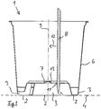
- Fig. 1 shows a plant pot 1 according to the invention, which stands above bases 2 of feet 3 on a set-up level 4.
- the feet 3 are formed in one piece with a circumferential wall 6 which has, for example, side ventilation slots.
- a circumferential wall 6 which has, for example, side ventilation slots.
- it can also be a transparent plastic wall.
- a floor 7 which is raised in relation to the installation level 4.
- the tip of a rod 8 inserted through a receptacle of the base 7 projects into the space formed between the installation level 4 and the base 7.
- the receptacle formed by the plant pot according to the invention with a tab 11 engages a part of the rod 8 located above the base 7 Torque acting in the direction of a central longitudinal central axis 9. This torque results from the different contact points of the rod 8 shown in the figure on the one hand on a tab 11 and on the other hand at the level of the bottom 7.
- the contact point on the tab 11 is located at the end of the tab pointing away from the central longitudinal central axis 9, while on the on the other side of the rod 8, the edge of the recess in the receptacle through which the rod 8 is pushed through forms at least one contact point, often a contact surface or line.
- These contact points are located at different heights above the installation level 4, so that the rod experiences a torque which is caused by a Components marked arrow 12 parallel to the installation plane 4 and in the direction of the central longitudinal central axis 9.
- the floor 7 has a plurality of receptacles arranged around a central dome 13, which (see FIG. Fig. 2 ) cover the floor 7.
- a receptacle is formed by a tab 15 delimited by a recess 14, the recess itself and the edge thereof.
- the recesses 14 have a main folding line 16, which is shown only with a small number of tabs. This line 16 forms the transition of the tab to the rest of the floor.
- the tabs point with in their in a use position Fig. 1 end resting on the rod 8 away from a central longitudinal central axis 9. A torque in the direction of the central longitudinal central axis 9 can be generated via each receptacle.
- Flow aids 17 are also arranged regularly around the central longitudinal central axis 9, so that the receptacles or their tabs 15 located in the outer bottom edge regions are also supplied with sufficient material during a production run.
- the cavities forming the tabs 15 of an associated tool are thus adequately supplied with plastic from a central injection point located on the axis 9.
- the different tabs 15 are at different distances from the central axis, so that a multitude of positions of a rod 8 is made possible.
- the flow aids 17 can be slightly raised compared to the rest of the base 7 and can be provided with falling flanks, so that a rod tip that meets a flow aid slides to the left or right to a tab.
- the recordings of the plant pot according to the invention Fig. 3 and 4 each have three tabs 15, which are separated from one another by a line of weakness or recess 18 with a Y-shaped shape.
- the individual tabs 15 are designed in the manner of an isosceles triangle with a longer base.
- the areas located between the flow aids can be provided with different numbers of receptacles. So are in the embodiment according to Fig. 4 six flow aids are provided in the radial direction, while in the embodiment according to Fig. 3 eight flow aids 17 can be used. This changes the number of receptacles arranged between the flow aids.
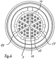
- each receptacle has more than one tab 15. What is common to these receptacles is that they can be transferred by inserting a rod into a position which at least partially folds down from the floor 7 and which is at least partially folded down relative to a surrounding area of the receptacle. When pushing the rod through a receptacle according to Figures 3 . 4 . 5 and 6 the associated tabs 15 exert a force evenly distributed along the circumference of a rod 8 on the latter.
- the clamping force exerted by the elastic tabs is distributed over their respective contact surface on the rod, so that the rod is more securely in the receptacle due to higher friction.
- Additional flow aids in the form of thickenings of the base 7 can be arranged between the individual tabs 15, which simultaneously form guides.
- a rod 8 is based on the example of FIG Fig. 3 up to for example the Fig. 6 supported more evenly around the circumference.
- the tabs are all V-shaped.
- the tip of a tab can additionally be provided with a shape adapted to the circumferential shape of the rod.
Landscapes
- Life Sciences & Earth Sciences (AREA)
- Environmental Sciences (AREA)
- Cultivation Receptacles Or Flower-Pots, Or Pots For Seedlings (AREA)
Description
- Die vorliegende Erfindung betrifft einen Pflanztopf zur Aufzucht von Orchideen, deren Rispe mit einem Stab gestützt werden kann, mit einem gegenüber einer unteren Aufstellebene erhöhten Boden, der wenigstens eine Aufnahme für einen Stab aufweist.
- Bei der Aufzucht von insbesondere Orchideen werden die Rispen zu einem bestimmten Zeitpunkt mit einem in einen Pflanztopf einzusteckenden Stab gestützt. Problematisch ist hierbei die Fixierung des Stabes. Einerseits kann der Stab durch Substrat und gegebenenfalls Wurzelwerk gestützt werden, was jedoch insbesondere bei losem Substrat für Orchideen und sich weiter ausbildendem Wurzelwerk zu Schiefstellungen des Stabes und mangelhafter Abstützung führen kann. Andererseits ist es bekannt, einen Stab durch eine im Boden eines Pflanztopfes vorzusehende Aufnahme in Form eines Loches hindurchzustecken, wobei der Durchmesser des Stabes auf das im Boden des Pflanztopfes befindliche Loch abzustimmen ist. Hierbei wird der Stab bei dessen korrekter Dimensionierung durch den Lochrand zwar gehalten, aufgrund der in etwa auf einer Höhe oberhalb einer waagerechten Standfläche am Stab verlaufenden Anlage des Lochrandes ergibt sich jedoch ebenfalls nur eine mangelhafte Abstützung.
- Ein entsprechender gattungsgemäßer Gegenstand ist der
DE 10 2008 024 741 A1 zu entnehmen. - Aus der
GB 2418339 GB 2405306 - Es ist daher Aufgabe der vorliegenden Erfindung, einen Pflanztopf dergestalt weiter zu bilden, dass ein in den Pflanztopf einzusteckender Stab ausreichend abgestützt werden kann.
- Die Aufgabe wird gelöst durch einen Pflanztopf gemäß Anspruch 1. Vorteilhafte Weiterbildungen eines Pflanztopfes sind den auf den Anspruch 1 rückbezogenen Unteransprüchen sowie der nachfolgenden Beschreibung zu entnehmen.
- Erfindungsgemäß ist der Aufnahme des Pflanztopfes zumindest eine Lasche zugeordnet, mittels der auf einen in die Aufnahme einsteckbaren oder einzusteckenden Stab eine Kraft ausgeübt werden kann. Diese Lasche stellt gegenüber den weiteren Anlagepunkten des Bodens bzw. der Aufnahme eine zusätzliche Führung oder Halterung dar, die den Stab zusätzlich fixieren kann.
- Hierbei ist die Lasche durch Einführen eines Stabes, d.h. bei bestimmungsgemäßer Verwendung des Pflanztopfes, durch die Aufnahme in eine teilweise gegenüber einem Umgebungsbereich der Aufnahme abgewinkelte oder abgeklappte, nach unten vom Boden abstehende Position überführbar. In der Gebrauchsstellung steht die Lasche somit als Teil des Bodens nach unten vom Rest des Bodens ab.
- Insbesondere kann zur gezielten Führung des Stabes in eine Vorzugsrichtung aufgrund der von der Lasche ausgeübten Kraft ein Drehmoment auf diesen ausgeübt werden. Hierbei wird der Stab mit seinem oberhalb des Bodens befindlichen Teil vorzugsweise in Richtung einer zentralen Längsmittelachse gedrückt bzw. gedreht. Erfindungsgemäß ist die Lasche Teil der Aufnahme und somit Teil des Bodens.
- Die von der Lasche auf einen in den Pflanztopf einzubringenden Stab auszuübende Kraft kann sich als Gegenkraft auf eine durch Einstecken des Stabes in den Pflanztopf aufgebrachte Kraft ergeben.
- Der Stab zum Stützen einer Rispe ist nicht notwendigerweise Teil der Erfindung. Des Weiteren ist die Lasche ein Teil des Pflanztopfes, welches in der Gebrauchsstellung mit Stab ein abgeklapptes, abgeknicktes oder gebogenes Ende aufweist.
- Anderenends geht die Lasche in den Pflanztopfboden über.
- Das Material des Bodens des Pflanztopfes oder des Pflanztopfes selbst kann hierbei so elastisch ausgebildet sein, dass die Lasche zwar nach unten bewegbar ist, der Rest Bodens jedoch ohne Weiteres in seiner Integrität bestehen bleiben kann. Hierbei ist Lasche mittels eines durch eine Schwächungslinie des Pflanztopfes ausgebildeten Filmscharniers mit dem Rest des Bodens verbunden, wobei die Lasche dann bei Einschieben eines Stabes abknicken oder abklappen kann. Insbesondere ist dieses Filmscharnier so stark ausgebildet, dass nach Anordnung des Stabes auf diesen eine Kraft ausgeübt werden kann. Bei einer ausreichend elastischen Lasche schmiegt sich diese teilweise an den Stab an, wodurch dieser insbesondere aufgrund von Reibungskräften besser gehalten werden kann.
- Durch eine in einer Gebrauchsstellung an dem Stab anliegende Lasche, die nach unten vom Boden in Richtung Aufstellebene absteht, wird auf den Stab unterhalb des Pflanztopfbodens eine Kraft ausgeübt. Sofern der Stab an weiteren Anlagepunkten der Aufnahme auf Bodenhöhe abgestützt ist, ergibt sich aufgrund der unterschiedlichen Höhe der Anlagepunkte der Lasche einerseits und der Aufnahme andererseits ein Drehmoment auf den Stab, welches insbesondere den oberhalb des Bodens befindlichen Teil des Stabes in Richtung einer zentralen Längsmittelachse drücken kann.
- Erfindungsgemäß ist die Lasche dergestalt ausgebildet, dass sie in einer Nichtbenutzungsposition ausgehend von ihrer Verbindung mit dem Rest des Bodens von einer zentralen Längsmittelachse wegführt. Sie kann hierbei beispielsweise dreieckig, mit einer von der zentralen Längsmittelachse wegführenden Spitze oder auch u- oder v-förmig ausgebildet sein. Die Verbindung zum Rest des Bodens ist durch eine Schwächungslinie bzw. durch ein Filmscharnier ausgebildet. Auch der Rest der Lasche ist durch bodenseitige Schwächungslinien ausgebildet. Dies ist insbesondere bei einer Vielzahl von in einem Boden ausgebildeten Aufnahmen von Vorteil. Der Boden ist somit so lange geschlossen, bis ein Stab durch eine Aufnahme durchgesteckt wird. Demzufolge tritt weniger Substratverlust auf.
- Die insbesondere aus dem Material des Bodens und mit diesem einstöckig hergestellte Lasche ist bei einer vorteilhaften Weiterbildung elastisch ausgebildet und kann sich insbesondere zumindest teilweise an einen in den Pflanztopf einzusteckenden Stab anlehnen, wodurch dieser besser geführt werden kann.
- Erfindungsgemäße Pflanztöpfe mit einer Mehrzahl von Aufnahmen im Bodenbereich machen die Anordnung eines einzusteckenden Stabes einfacher, wenn sie mehr oder weniger regelmäßig über den Boden verteilt sind. Auch eine unregelmäßige Verteilung der einzelnen Aufnahmen auf den Boden kann die Anordnung eines Stabes verbessern. Der Stab kann ohne auf bestimmte Zielbereiche achten zu müssen in den Boden eingesteckt werden. Hierbei ist zu bedenken, dass die Stäbe insbesondere dann erst in den Pflanztopf eingesteckt werden, wenn bereits Pflanzen und Substrat im Pflanztopf angeordnet sind und der Boden des Topfes von oben nicht mehr sichtbar ist.
- Vorzugsweise sind zumindest zwei Aufnahmen von einer zentralen Längsmittelachse wenigstens teilweise unterschiedlich beabstandet, so dass auf unterschiedlichen Umfangslinien um eine zentrale Längsmittelachse Aufnahmen angeordnet sind. Dies vereinfacht die Verwendung des Stützstabes weiterhin.
- Bei einer mit einer oder mehreren elastischen oder abknickbaren Laschen versehenen Aufnahme können vorteilhafterweise Stäbe mit verschiedenen Durchmessern verwendet werden.
- Bei einer weiteren vorteilhaften Ausgestaltung der Erfindung sind die Aufnahmen um einen zentralen, keine Aufnahme aufweisenden Bereich des Bodens angeordnet, wodurch insbesondere bei einer Entnahme aus einem Übertopf keine Beschädigung des Bodens auftritt.
- Erfindungsgemäß ist der Topf insbesondere im Spritzgußverfahren hergestellt, wobei der mit den Aufnahmen versehene Topfboden Fließhilfen aufweisen kann, die auch in Randbereichen des Pflanztopfes eine gute Ausbildung von Laschen gewährleisten. Eine solche Fließhilfe kann von einem zentralen Anspritzpunkt in radialer Richtung durch größere Durchmesser im Werkzeug bewirkt werden, wodurch auch vom Anspritzpunkt entfernt liegende und fein ausgebildete Laschen mit ausreichend Material versehen werden können. Der erfindungsgemäße Pflanztopf weist dann dickere Rippen im Boden auf, die gleichzeitig eine Stabilisierung des Bodens bewirken.
- Einzelne Aufnahmen können vorteilhafterweise über Führungen beispielsweise durch Erhebungen oder Verdickungen des Bodens voneinander getrennt werden, so dass von oben in den Pflanztopf einzusteckende Stäbe in Richtung einer Schwächungslinie bzw. einer Laschenspitze geführt werden. Dies erleichtert ein Einstecken eines vorzusehenden Stabes. Solche Führungen können insbesondere mit Fließhilfen verbunden sein oder gleichzeitig Fließhilfen darstellen, was die Herstellung des Pflanztopfes weiter vereinfacht.
- Eine auf einen einzusteckenden Stab in dessen Haltestellung im Pflanztopf ausgeübte Kraft kann insbesondere dann vergrößert werden, wenn die Lasche bei einem nach unten aus dem Boden Herausdrücken, -klappen oder -biegen gegen eine Abstützung stößt, die teilelastisch sein kann. Hierbei kann es sich beispielsweise um Ecken, Vorsprünge oder auch angeformte Federn des Bodens, die insbesondere einstückig mit diesem verbunden sein können, handeln.
- Weitere Vorteile und Einzelheiten der Erfindung lassen sich der nachfolgenden Figurenbeschreibung entnehmen. Schematisch dargestellt zeigt:
- Fig. 1
- einen Längsschnitt durch einen erfindungsgemäßen Pflanztopf
- Fig. 2
- den Gegenstand nach
Figur 1 in einer Draufsicht - Fig. 3
- einen weiteren erfindungsgemäßen Gegenstand in einer Draufsicht,
- Fig. 4
- einen weiteren erfindungsgemäßen Gegenstand in einer Draufsicht,
- Fig. 5
- einen weiteren erfindungsgemäßen Gegenstand in einer Draufsicht,
- Fig. 6
- einen weiteren erfindungsgemäßen Gegenstand in einer Draufsicht.
- Gleich oder ähnlich wirkende Teile sind - sofern dienlich - mit identischen Bezugsziffern versehen. Einzelne technische Merkmale der nachfolgend beschriebenen Ausführungsbeispiele können auch mit den Merkmalen der vorbeschriebenen Ausführungsbeispiele zu erfindungsgemäßen Weiterbildungen führen.
-
Fig. 1 zeigt einen erfindungsgemäßen Pflanztopf 1, der über Unterseiten 2 von Füßen 3 auf einer Aufstellebene 4 steht. Die Füße 3 sind bei diesem Ausführungsbeispiel einstückig mit einer umlaufenden Wand 6 ausgebildet, die beispielsweise seitliche Lüftungsschlitze aufweist. Alternativ oder ergänzend kann es sich auch um eine durchsichtige Kunststoffwand handeln. - Ebenfalls einstückig mit den Füßen 3 und somit auch mit der Wand 6 ist ein Boden 7 ausgebildet, der gegenüber der Aufstellebene 4 erhöht ist. In den zwischen Aufstellebene 4 und Boden 7 ausgebildeten Zwischenraum ragt die Spitze eines durch eine Aufnahme des Bodens 7 hindurch gesteckten Stabes 8. Durch die von dem erfindungsgemäßen Pflanztopf mit einer Lasche 11 ausgebildete Aufnahme wird auf einen oberhalb des Bodens 7 befindlichen Teil des Stabes 8 ein in Richtung einer zentralen Längsmittelachse 9 wirkenden Drehmoment ausgeübt. Dieses Drehmoment ergibt sich aufgrund der in der Figur dargestellten unterschiedlichen Anlagepunkte des Stabes 8 einerseits an einer Lasche 11 und andererseits auf Höhe des Bodens 7. Der Anlagepunkt an der Lasche 11 liegt an dem von der zentralen Längsmittelachse 9 wegweisende Ende der Lasche, während auf der anderen Seite des Stabes 8 der Rand der Ausnehmung der Aufnahme, durch die der Stab 8 durchgesteckt ist, wenigstens einen Anlagepunkt, oftmals eine Anlagefläche oder -linieausbildet. Diese Anlagepunkte befinden sich in unterschiedlichen Höhen über der Aufstellebene 4, so dass der Stab ein Drehmoment erfährt, welches eine durch einen Pfeil 12 gekennzeichnete Komponente parallel zur Aufstellebene 4 und in Richtung der zentralen Längsmittelachse 9 aufweist.
- Der Boden 7 weist eine Vielzahl von um einen zentralen Dom 13 herum angeordnete Aufnahmen auf, die (sh.
Fig. 2 ) den Boden 7 bedecken. Eine Aufnahme wird hierbei durch eine von einer Ausnehmung 14 begrenzte Lasche 15, der Ausnehmung selbst sowie deren Rand ausgebildet. Die Ausnehmungen 14 weisen eine Hauptklapplinie 16 auf, die nur bei einer geringen Anzahl von Laschen eingezeichnet ist. Diese Linie 16 bildet den Übergang der Lasche zum Rest des Bodens aus. Die Laschen weisen mit ihrem in einer Gebrauchstellung gemäßFig. 1 am Stab 8 anliegenden Ende von einer zentralen Längsmittelachse 9 weg. Über jede Aufnahme kann ein Drehmoment in Richtung der zentralen Längsmittelachse 9 erzeugt werden. - Fließhilfen 17 sind ebenfalls regelmäßig um die zentrale Längsmittelachse 9 angeordnet, damit auch die in den äußeren Bodenrandbereichen befindlichen Aufnahmen bzw. deren Laschen 15 während eines Fertigungsganges mit ausreichend Material versorgt werden. Die die Laschen 15 ausbildenden Hohlräume eines zugehörigen Werkzeugs werden so von einem zentralen Anspritzpunkt, der sich auf der Achse 9 befindet, ausreichend mit Kunststoff versorgt.
- Die verschiedenen Laschen 15 weisen unterschiedliche Entfernungen von der Zentralachse auf, so dass eine Vielzahl von Positionierungen eines Stabes 8 ermöglicht wird. Die Fließhilfen 17 können gegenüber dem Rest des Bodens 7 geringfügig erhöht und mit abfallenden Flanken versehen sein, so dass eine Stabspitze, die auf eine Fließhilfe trifft, nach links oder rechts hin zu einer Lasche abgleitet.
- Die Aufnahmen des erfindungsgemäßen Pflanztopfs gemäß
Fig. 3 und4 weisen jeweils drei Laschen 15 auf, die über eine Schwächungslinie oder Ausnehmung 18 mit einer Y-förmigen Form voneinander getrennt sind. Die einzelnen Laschen 15 sind nach Art eines gleichschenkligen Dreiecks mit einer längeren Basis ausgebildet. - Je nach Anzahl der vorzusehenden Fließhilfen 17 können die zwischen den Fließhilfen befindlichen Bereiche mit unterschiedlich vielen Aufnahmen versehen werden. So sind in dem Ausführungsbeispiel gemäß
Fig. 4 sechs Fließhilfen in radialer Richtung vorgesehen, während in dem Ausführungsbeispiel gemäßFig. 3 acht Fließhilfen 17 verwendet werden. Hierdurch ändert sich die Anzahl der zwischen den Fließhilfen angeordneten Aufnahmen. - In den Ausführungsbeispielen nach den
Figuren 3 bis 6 weist jede Aufnahme mehr als eine Lasche 15 auf. Gemeinsam ist diesen Aufnahmen, dass sie durch Einführung eines Stabes in eine gegenüber einem Umgebungsbereich der Aufnahme wenigstens teilweise abgeklappte nach unten von dem Boden 7 abstehende Position überführbar sind. Bei einem Durchstecken des Stabes durch eine Aufnahme nach denFiguren 3 ,4 ,5 und6 wird von den zugehörigen Laschen 15 eine gleichmäßig entlang des Umfangs eines Stabes 8 verteilte Kraft auf diesen ausgeübt. Insbesondere bei den etwas längeren Laschen 15 der Ausführungsbeispiele gemäßFigur 5 und6 ist die von den elastischen Laschen ausgeübte Klemmkraft über deren jeweilige Anlagefläche an dem Stab verteilt, so dass sich der Stab aufgrund höherer Reibung sicherer in der Aufnahme befindet. Zwischen den einzelnen, Laschen 15 aufweisenden Aufnahmen können zusätzliche Fließhilfen in Form von Verdickungen des Bodens 7 angeordnet sein, die gleichzeitig Führungen ausbilden. Mit zunehmender Anzahl von Laschen wird ein Stab 8 ausgehend von dem Beispiel derFig. 3 bis hin zum Beispiel derFig. 6 gleichmäßiger entlang des Umfangs verteilt abgestützt. Hierbei sind die Laschen alle v-förmig ausgebildet. Zur noch besseren Anlage einer Lasche an einen Stab kann die Spitze einer Lasche zusätzlich mit einer auf die Umfangsform des Stabes angepassten Form versehen sein.
Claims (10)
- Pflanztopf zur Aufzucht von Orchideen, deren Rispe mit einem Stab (8) gestützt werden kann, mit einem gegenüber einer unteren Aufstellebene (4) erhöhten Boden (7) des Pflanztopfes, der eine Mehrzahl von Aufnahmen für einen Stab (8) aufweist, dadurch gekennzeichnet, dass den Aufnahmen jeweils zumindest eine als Teil des Bodens ausgebildete Lasche (15) zugeordnet ist, mittels der auf einen in die Aufnahme einsteckbaren Stab (8) eine Kraft ausübbar ist, wobei die Laschen (15) jeweils durch Einführen des Stabes (8) durch die Aufnahme in eine gegenüber einem Umgebungsbereich der Aufnahme wenigstens teilweise abgeklappte, nach unten von dem Boden (7) abstehende Position überführbar sind, wobei die Laschen (15) in einer Nichtbenutzungsposition ausgehend von ihrer Verbindung (16) mit dem Rest des Bodens (7) von einer zentralen Längsmittelachse (9) wegführen und durch bodenseitige Schwächungslinien ausgebildet sind.
- Pflanztopf nach Anspruch 1, dadurch gekennzeichnet, dass die Lasche (15) elastisch ausgebildet ist.
- Pflanztopf nach Anspruch 2, dadurch gekennzeichnet, dass die Lasche (15) aufgrund ihrer Elastizität zur zumindest teilweisen Anlage an den in den Pflanztopf einzusteckenden Stab (8) ausgebildet ist.
- Pflanztopf nach einem der vorherigen Ansprüche, dadurch gekennzeichnet, dass die Aufnahme wenigstens eine weitere Lasche aufweist.
- Pflanztopf nach einem der vorherigen Ansprüche, dadurch gekennzeichnet, dass die Aufnahmen über eine Führung (17) voneinander getrennt sind.
- Pflanztopf nach einem der vorherigen Ansprüche, dadurch gekennzeichnet, dass zumindest zwei Aufnahmen von einer zentralen Längsmittelachse (9) unterschiedlich weit beabstandet sind.
- Pflanztopf nach einem der vorherigen Ansprüche, dadurch gekennzeichnet, dass die Aufnahmen um einen zentralen und keine Aufnahmen aufweisenden Bodenbereich (13) herum angeordnet sind.
- Pflanztopf nach einem der vorherigen Ansprüche, gekennzeichnet durch wenigstens eine vom Boden ausgebildete Fließhilfe.
- Pflanztopf nach einem der vorherigen Ansprüche, gekennzeichnet durch einen vorzugsweise aus Bambus hergestellten Stab zum Stützen einer Rispe.
- Pflanztopf nach einem der vorherigen Ansprüche, gekennzeichnet durch eine Abstützung der Lasche (15), die durch eine auf einer Unterseite des Bodens (7) angeordnete Anformung ausgebildet wird.
Applications Claiming Priority (2)
| Application Number | Priority Date | Filing Date | Title |
|---|---|---|---|
| DE202009015315U DE202009015315U1 (de) | 2009-11-12 | 2009-11-12 | Pflanztopf |
| PCT/EP2010/006011 WO2011057693A1 (de) | 2009-11-12 | 2010-10-01 | Pflanztopf |
Publications (2)
| Publication Number | Publication Date |
|---|---|
| EP2498591A1 EP2498591A1 (de) | 2012-09-19 |
| EP2498591B1 true EP2498591B1 (de) | 2020-02-26 |
Family
ID=43414282
Family Applications (1)
| Application Number | Title | Priority Date | Filing Date |
|---|---|---|---|
| EP10771644.1A Active EP2498591B1 (de) | 2009-11-12 | 2010-10-01 | Pflanztopf |
Country Status (3)
| Country | Link |
|---|---|
| EP (1) | EP2498591B1 (de) |
| DE (1) | DE202009015315U1 (de) |
| WO (1) | WO2011057693A1 (de) |
Families Citing this family (2)
| Publication number | Priority date | Publication date | Assignee | Title |
|---|---|---|---|---|
| CN102511293A (zh) * | 2011-12-29 | 2012-06-27 | 贵州省农作物品种资源研究所 | 野生流苏贝母兰的人工栽培方法 |
| DE202024100718U1 (de) * | 2024-02-14 | 2025-05-20 | Pöppelmann Holding GmbH & Co. KG | Pflanztopf für die Orchideenkultivierung |
Family Cites Families (5)
| Publication number | Priority date | Publication date | Assignee | Title |
|---|---|---|---|---|
| DE4120745A1 (de) * | 1991-06-24 | 1991-12-12 | Fremmer Hans Kilian | Pflanzenanker |
| US6474266B1 (en) * | 1999-07-01 | 2002-11-05 | Sea Side Innovations Llc | Plant anchor |
| GB2405306B (en) * | 2003-08-29 | 2007-01-03 | Christopher Matthew Felton | Plant support system |
| GB2418339A (en) * | 2004-09-22 | 2006-03-29 | Richard Peter Pickard | Plant pot cane holder |
| NL2000657C2 (nl) * | 2007-05-22 | 2008-11-25 | Voskamp Vollebregt Holding B V | Plantpot, alsmede combinatie met staander en werkwijze. |
-
2009
- 2009-11-12 DE DE202009015315U patent/DE202009015315U1/de not_active Expired - Lifetime
-
2010
- 2010-10-01 WO PCT/EP2010/006011 patent/WO2011057693A1/de not_active Ceased
- 2010-10-01 EP EP10771644.1A patent/EP2498591B1/de active Active
Non-Patent Citations (1)
| Title |
|---|
| None * |
Also Published As
| Publication number | Publication date |
|---|---|
| WO2011057693A1 (de) | 2011-05-19 |
| EP2498591A1 (de) | 2012-09-19 |
| DE202009015315U1 (de) | 2011-03-24 |
Similar Documents
| Publication | Publication Date | Title |
|---|---|---|
| EP2387876B1 (de) | Pflanz-Anordnung | |
| EP1068053B1 (de) | Vorrichtung zum entfernen von ausbrechteilen aus einem werkstoffbogen oder dergleichen | |
| DE3300590C2 (de) | Flaschenkasten aus Kunststoff | |
| EP2943239B1 (de) | Befestigungselement und spritze | |
| DE102009006542A1 (de) | Verankerungsvorrichtung | |
| WO2023099243A1 (de) | Abstandshalter zum halten von übereinandergestapelten pipettenspitzenträgern auf abstand voneinander | |
| DE102012017899B4 (de) | Halter für einen langgestreckten Gegenstand | |
| DE202012100582U1 (de) | Haltevorrichtung, insbesondere Verpackung, zur Fixierung von stehenden Tuben | |
| DE102015011768B4 (de) | Flexible Schutzkappe für längliche Gegenstände | |
| WO2011057693A1 (de) | Pflanztopf | |
| DE2918530A1 (de) | Halterung, insbesondere zur verlegung und befestigung von rohren von fussbodenheizungen auf fussboeden | |
| DE69106320T2 (de) | Trogförmiger Behälter zum Verpacken von Obst, Gemüse oder dergleichen. | |
| EP2703576B1 (de) | Abdeckvorrichtung zur Überdeckung des Rohreintritts eines Ablaufelementes eines Entwässerungssystems | |
| DE102008024741A1 (de) | Pflanzgefäß, sowie Kombination mit Stütze und Verfahren | |
| DE19957977B4 (de) | Vorrichtung aus Abdeckelement und Gewindebolzen | |
| DE202010015471U1 (de) | Topfdisplay für Pflanztöpfe | |
| EP1932972B1 (de) | Spülkasten mit kombinierter Füllventil- und Ablaufventilsitzhalterung | |
| DE102022112571B3 (de) | Pflanzenstützgitter | |
| EP1312449A2 (de) | Vorrichtung zum Entfernen von Ausbrechteilen aus einem Werkstoffbogen od.dgl. | |
| EP2303071B1 (de) | Vorrichtung zur erhöhung der standsicherheit von gefässen, wie töpfen, vasen oder dergleichen | |
| DE102022114037A1 (de) | Bürstenkopf für eine WC-Bürste | |
| DE3042571C2 (de) | Zündverteiler für Brennkraftmaschinen | |
| DE202020101592U1 (de) | Blumenkasten | |
| DE102024102912A1 (de) | Magnetadapter | |
| DE10229543A1 (de) | Anordnung zur Positionierung von Strukturelementen an einer Tragstange eines Kleinmöbels |
Legal Events
| Date | Code | Title | Description |
|---|---|---|---|
| PUAI | Public reference made under article 153(3) epc to a published international application that has entered the european phase |
Free format text: ORIGINAL CODE: 0009012 |
|
| 17P | Request for examination filed |
Effective date: 20120314 |
|
| AK | Designated contracting states |
Kind code of ref document: A1 Designated state(s): AL AT BE BG CH CY CZ DE DK EE ES FI FR GB GR HR HU IE IS IT LI LT LU LV MC MK MT NL NO PL PT RO SE SI SK SM TR |
|
| DAX | Request for extension of the european patent (deleted) | ||
| STAA | Information on the status of an ep patent application or granted ep patent |
Free format text: STATUS: EXAMINATION IS IN PROGRESS |
|
| 17Q | First examination report despatched |
Effective date: 20171006 |
|
| REG | Reference to a national code |
Ref country code: DE Ref legal event code: R079 Ref document number: 502010016509 Country of ref document: DE Free format text: PREVIOUS MAIN CLASS: A01G0009120000 Ipc: A01G0009020000 |
|
| GRAP | Despatch of communication of intention to grant a patent |
Free format text: ORIGINAL CODE: EPIDOSNIGR1 |
|
| STAA | Information on the status of an ep patent application or granted ep patent |
Free format text: STATUS: GRANT OF PATENT IS INTENDED |
|
| RIC1 | Information provided on ipc code assigned before grant |
Ipc: A01G 9/12 20060101ALI20190617BHEP Ipc: A01G 9/02 20180101AFI20190617BHEP |
|
| INTG | Intention to grant announced |
Effective date: 20190719 |
|
| GRAJ | Information related to disapproval of communication of intention to grant by the applicant or resumption of examination proceedings by the epo deleted |
Free format text: ORIGINAL CODE: EPIDOSDIGR1 |
|
| STAA | Information on the status of an ep patent application or granted ep patent |
Free format text: STATUS: EXAMINATION IS IN PROGRESS |
|
| GRAP | Despatch of communication of intention to grant a patent |
Free format text: ORIGINAL CODE: EPIDOSNIGR1 |
|
| STAA | Information on the status of an ep patent application or granted ep patent |
Free format text: STATUS: GRANT OF PATENT IS INTENDED |
|
| INTC | Intention to grant announced (deleted) | ||
| INTG | Intention to grant announced |
Effective date: 20191009 |
|
| GRAS | Grant fee paid |
Free format text: ORIGINAL CODE: EPIDOSNIGR3 |
|
| GRAA | (expected) grant |
Free format text: ORIGINAL CODE: 0009210 |
|
| STAA | Information on the status of an ep patent application or granted ep patent |
Free format text: STATUS: THE PATENT HAS BEEN GRANTED |
|
| AK | Designated contracting states |
Kind code of ref document: B1 Designated state(s): AL AT BE BG CH CY CZ DE DK EE ES FI FR GB GR HR HU IE IS IT LI LT LU LV MC MK MT NL NO PL PT RO SE SI SK SM TR |
|
| REG | Reference to a national code |
Ref country code: GB Ref legal event code: FG4D Free format text: NOT ENGLISH |
|
| REG | Reference to a national code |
Ref country code: CH Ref legal event code: EP |
|
| REG | Reference to a national code |
Ref country code: AT Ref legal event code: REF Ref document number: 1236519 Country of ref document: AT Kind code of ref document: T Effective date: 20200315 |
|
| REG | Reference to a national code |
Ref country code: IE Ref legal event code: FG4D Free format text: LANGUAGE OF EP DOCUMENT: GERMAN |
|
| REG | Reference to a national code |
Ref country code: DE Ref legal event code: R096 Ref document number: 502010016509 Country of ref document: DE |
|
| REG | Reference to a national code |
Ref country code: NL Ref legal event code: FP |
|
| PG25 | Lapsed in a contracting state [announced via postgrant information from national office to epo] |
Ref country code: FI Free format text: LAPSE BECAUSE OF FAILURE TO SUBMIT A TRANSLATION OF THE DESCRIPTION OR TO PAY THE FEE WITHIN THE PRESCRIBED TIME-LIMIT Effective date: 20200226 Ref country code: NO Free format text: LAPSE BECAUSE OF FAILURE TO SUBMIT A TRANSLATION OF THE DESCRIPTION OR TO PAY THE FEE WITHIN THE PRESCRIBED TIME-LIMIT Effective date: 20200526 |
|
| REG | Reference to a national code |
Ref country code: LT Ref legal event code: MG4D |
|
| PG25 | Lapsed in a contracting state [announced via postgrant information from national office to epo] |
Ref country code: BG Free format text: LAPSE BECAUSE OF FAILURE TO SUBMIT A TRANSLATION OF THE DESCRIPTION OR TO PAY THE FEE WITHIN THE PRESCRIBED TIME-LIMIT Effective date: 20200526 Ref country code: HR Free format text: LAPSE BECAUSE OF FAILURE TO SUBMIT A TRANSLATION OF THE DESCRIPTION OR TO PAY THE FEE WITHIN THE PRESCRIBED TIME-LIMIT Effective date: 20200226 Ref country code: GR Free format text: LAPSE BECAUSE OF FAILURE TO SUBMIT A TRANSLATION OF THE DESCRIPTION OR TO PAY THE FEE WITHIN THE PRESCRIBED TIME-LIMIT Effective date: 20200527 Ref country code: LV Free format text: LAPSE BECAUSE OF FAILURE TO SUBMIT A TRANSLATION OF THE DESCRIPTION OR TO PAY THE FEE WITHIN THE PRESCRIBED TIME-LIMIT Effective date: 20200226 Ref country code: IS Free format text: LAPSE BECAUSE OF FAILURE TO SUBMIT A TRANSLATION OF THE DESCRIPTION OR TO PAY THE FEE WITHIN THE PRESCRIBED TIME-LIMIT Effective date: 20200626 Ref country code: SE Free format text: LAPSE BECAUSE OF FAILURE TO SUBMIT A TRANSLATION OF THE DESCRIPTION OR TO PAY THE FEE WITHIN THE PRESCRIBED TIME-LIMIT Effective date: 20200226 |
|
| PG25 | Lapsed in a contracting state [announced via postgrant information from national office to epo] |
Ref country code: CZ Free format text: LAPSE BECAUSE OF FAILURE TO SUBMIT A TRANSLATION OF THE DESCRIPTION OR TO PAY THE FEE WITHIN THE PRESCRIBED TIME-LIMIT Effective date: 20200226 Ref country code: SK Free format text: LAPSE BECAUSE OF FAILURE TO SUBMIT A TRANSLATION OF THE DESCRIPTION OR TO PAY THE FEE WITHIN THE PRESCRIBED TIME-LIMIT Effective date: 20200226 Ref country code: RO Free format text: LAPSE BECAUSE OF FAILURE TO SUBMIT A TRANSLATION OF THE DESCRIPTION OR TO PAY THE FEE WITHIN THE PRESCRIBED TIME-LIMIT Effective date: 20200226 Ref country code: EE Free format text: LAPSE BECAUSE OF FAILURE TO SUBMIT A TRANSLATION OF THE DESCRIPTION OR TO PAY THE FEE WITHIN THE PRESCRIBED TIME-LIMIT Effective date: 20200226 Ref country code: SM Free format text: LAPSE BECAUSE OF FAILURE TO SUBMIT A TRANSLATION OF THE DESCRIPTION OR TO PAY THE FEE WITHIN THE PRESCRIBED TIME-LIMIT Effective date: 20200226 Ref country code: DK Free format text: LAPSE BECAUSE OF FAILURE TO SUBMIT A TRANSLATION OF THE DESCRIPTION OR TO PAY THE FEE WITHIN THE PRESCRIBED TIME-LIMIT Effective date: 20200226 Ref country code: ES Free format text: LAPSE BECAUSE OF FAILURE TO SUBMIT A TRANSLATION OF THE DESCRIPTION OR TO PAY THE FEE WITHIN THE PRESCRIBED TIME-LIMIT Effective date: 20200226 Ref country code: LT Free format text: LAPSE BECAUSE OF FAILURE TO SUBMIT A TRANSLATION OF THE DESCRIPTION OR TO PAY THE FEE WITHIN THE PRESCRIBED TIME-LIMIT Effective date: 20200226 Ref country code: PT Free format text: LAPSE BECAUSE OF FAILURE TO SUBMIT A TRANSLATION OF THE DESCRIPTION OR TO PAY THE FEE WITHIN THE PRESCRIBED TIME-LIMIT Effective date: 20200719 |
|
| REG | Reference to a national code |
Ref country code: DE Ref legal event code: R097 Ref document number: 502010016509 Country of ref document: DE |
|
| PLBE | No opposition filed within time limit |
Free format text: ORIGINAL CODE: 0009261 |
|
| STAA | Information on the status of an ep patent application or granted ep patent |
Free format text: STATUS: NO OPPOSITION FILED WITHIN TIME LIMIT |
|
| PG25 | Lapsed in a contracting state [announced via postgrant information from national office to epo] |
Ref country code: IT Free format text: LAPSE BECAUSE OF FAILURE TO SUBMIT A TRANSLATION OF THE DESCRIPTION OR TO PAY THE FEE WITHIN THE PRESCRIBED TIME-LIMIT Effective date: 20200226 |
|
| 26N | No opposition filed |
Effective date: 20201127 |
|
| PG25 | Lapsed in a contracting state [announced via postgrant information from national office to epo] |
Ref country code: SI Free format text: LAPSE BECAUSE OF FAILURE TO SUBMIT A TRANSLATION OF THE DESCRIPTION OR TO PAY THE FEE WITHIN THE PRESCRIBED TIME-LIMIT Effective date: 20200226 Ref country code: PL Free format text: LAPSE BECAUSE OF FAILURE TO SUBMIT A TRANSLATION OF THE DESCRIPTION OR TO PAY THE FEE WITHIN THE PRESCRIBED TIME-LIMIT Effective date: 20200226 |
|
| REG | Reference to a national code |
Ref country code: CH Ref legal event code: PL |
|
| GBPC | Gb: european patent ceased through non-payment of renewal fee |
Effective date: 20201001 |
|
| PG25 | Lapsed in a contracting state [announced via postgrant information from national office to epo] |
Ref country code: LU Free format text: LAPSE BECAUSE OF NON-PAYMENT OF DUE FEES Effective date: 20201001 Ref country code: MC Free format text: LAPSE BECAUSE OF FAILURE TO SUBMIT A TRANSLATION OF THE DESCRIPTION OR TO PAY THE FEE WITHIN THE PRESCRIBED TIME-LIMIT Effective date: 20200226 |
|
| REG | Reference to a national code |
Ref country code: BE Ref legal event code: MM Effective date: 20201031 |
|
| PG25 | Lapsed in a contracting state [announced via postgrant information from national office to epo] |
Ref country code: FR Free format text: LAPSE BECAUSE OF NON-PAYMENT OF DUE FEES Effective date: 20201031 |
|
| PG25 | Lapsed in a contracting state [announced via postgrant information from national office to epo] |
Ref country code: GB Free format text: LAPSE BECAUSE OF NON-PAYMENT OF DUE FEES Effective date: 20201001 Ref country code: LI Free format text: LAPSE BECAUSE OF NON-PAYMENT OF DUE FEES Effective date: 20201031 Ref country code: BE Free format text: LAPSE BECAUSE OF NON-PAYMENT OF DUE FEES Effective date: 20201031 Ref country code: CH Free format text: LAPSE BECAUSE OF NON-PAYMENT OF DUE FEES Effective date: 20201031 |
|
| PG25 | Lapsed in a contracting state [announced via postgrant information from national office to epo] |
Ref country code: IE Free format text: LAPSE BECAUSE OF NON-PAYMENT OF DUE FEES Effective date: 20201001 |
|
| REG | Reference to a national code |
Ref country code: AT Ref legal event code: MM01 Ref document number: 1236519 Country of ref document: AT Kind code of ref document: T Effective date: 20201001 |
|
| PG25 | Lapsed in a contracting state [announced via postgrant information from national office to epo] |
Ref country code: AT Free format text: LAPSE BECAUSE OF NON-PAYMENT OF DUE FEES Effective date: 20201001 |
|
| PG25 | Lapsed in a contracting state [announced via postgrant information from national office to epo] |
Ref country code: TR Free format text: LAPSE BECAUSE OF FAILURE TO SUBMIT A TRANSLATION OF THE DESCRIPTION OR TO PAY THE FEE WITHIN THE PRESCRIBED TIME-LIMIT Effective date: 20200226 Ref country code: MT Free format text: LAPSE BECAUSE OF FAILURE TO SUBMIT A TRANSLATION OF THE DESCRIPTION OR TO PAY THE FEE WITHIN THE PRESCRIBED TIME-LIMIT Effective date: 20200226 Ref country code: CY Free format text: LAPSE BECAUSE OF FAILURE TO SUBMIT A TRANSLATION OF THE DESCRIPTION OR TO PAY THE FEE WITHIN THE PRESCRIBED TIME-LIMIT Effective date: 20200226 |
|
| PG25 | Lapsed in a contracting state [announced via postgrant information from national office to epo] |
Ref country code: MK Free format text: LAPSE BECAUSE OF FAILURE TO SUBMIT A TRANSLATION OF THE DESCRIPTION OR TO PAY THE FEE WITHIN THE PRESCRIBED TIME-LIMIT Effective date: 20200226 Ref country code: AL Free format text: LAPSE BECAUSE OF FAILURE TO SUBMIT A TRANSLATION OF THE DESCRIPTION OR TO PAY THE FEE WITHIN THE PRESCRIBED TIME-LIMIT Effective date: 20200226 |
|
| PGFP | Annual fee paid to national office [announced via postgrant information from national office to epo] |
Ref country code: NL Payment date: 20251023 Year of fee payment: 16 |
|
| PGFP | Annual fee paid to national office [announced via postgrant information from national office to epo] |
Ref country code: DE Payment date: 20251020 Year of fee payment: 16 |