EP2498038B1 - Fin member for heat exchanger - Google Patents
Fin member for heat exchanger Download PDFInfo
- Publication number
- EP2498038B1 EP2498038B1 EP10828076.9A EP10828076A EP2498038B1 EP 2498038 B1 EP2498038 B1 EP 2498038B1 EP 10828076 A EP10828076 A EP 10828076A EP 2498038 B1 EP2498038 B1 EP 2498038B1
- Authority
- EP
- European Patent Office
- Prior art keywords
- engagement recesses
- fin member
- pipe member
- sections
- fin
- Prior art date
- Legal status (The legal status is an assumption and is not a legal conclusion. Google has not performed a legal analysis and makes no representation as to the accuracy of the status listed.)
- Active
Links
- 239000012530 fluid Substances 0.000 claims description 6
- 239000000463 material Substances 0.000 claims description 4
- 230000015572 biosynthetic process Effects 0.000 description 6
- 238000005260 corrosion Methods 0.000 description 4
- 230000007797 corrosion Effects 0.000 description 4
- 238000000034 method Methods 0.000 description 4
- 239000013049 sediment Substances 0.000 description 4
- 238000010521 absorption reaction Methods 0.000 description 2
- 238000003795 desorption Methods 0.000 description 2
- 239000000446 fuel Substances 0.000 description 2
- 230000001105 regulatory effect Effects 0.000 description 2
- 230000003247 decreasing effect Effects 0.000 description 1
- 230000003467 diminishing effect Effects 0.000 description 1
- 230000000694 effects Effects 0.000 description 1
- 230000001788 irregular Effects 0.000 description 1
- 230000001737 promoting effect Effects 0.000 description 1
- 230000003019 stabilising effect Effects 0.000 description 1
- 230000008961 swelling Effects 0.000 description 1
Images


Classifications
-
- F—MECHANICAL ENGINEERING; LIGHTING; HEATING; WEAPONS; BLASTING
- F28—HEAT EXCHANGE IN GENERAL
- F28F—DETAILS OF HEAT-EXCHANGE AND HEAT-TRANSFER APPARATUS, OF GENERAL APPLICATION
- F28F13/00—Arrangements for modifying heat-transfer, e.g. increasing, decreasing
- F28F13/06—Arrangements for modifying heat-transfer, e.g. increasing, decreasing by affecting the pattern of flow of the heat-exchange media
- F28F13/12—Arrangements for modifying heat-transfer, e.g. increasing, decreasing by affecting the pattern of flow of the heat-exchange media by creating turbulence, e.g. by stirring, by increasing the force of circulation
-
- B—PERFORMING OPERATIONS; TRANSPORTING
- B21—MECHANICAL METAL-WORKING WITHOUT ESSENTIALLY REMOVING MATERIAL; PUNCHING METAL
- B21D—WORKING OR PROCESSING OF SHEET METAL OR METAL TUBES, RODS OR PROFILES WITHOUT ESSENTIALLY REMOVING MATERIAL; PUNCHING METAL
- B21D53/00—Making other particular articles
- B21D53/02—Making other particular articles heat exchangers or parts thereof, e.g. radiators, condensers fins, headers
- B21D53/022—Making the fins
-
- F—MECHANICAL ENGINEERING; LIGHTING; HEATING; WEAPONS; BLASTING
- F28—HEAT EXCHANGE IN GENERAL
- F28F—DETAILS OF HEAT-EXCHANGE AND HEAT-TRANSFER APPARATUS, OF GENERAL APPLICATION
- F28F1/00—Tubular elements; Assemblies of tubular elements
- F28F1/10—Tubular elements and assemblies thereof with means for increasing heat-transfer area, e.g. with fins, with projections, with recesses
- F28F1/12—Tubular elements and assemblies thereof with means for increasing heat-transfer area, e.g. with fins, with projections, with recesses the means being only outside the tubular element
- F28F1/126—Tubular elements and assemblies thereof with means for increasing heat-transfer area, e.g. with fins, with projections, with recesses the means being only outside the tubular element consisting of zig-zag shaped fins
-
- B—PERFORMING OPERATIONS; TRANSPORTING
- B21—MECHANICAL METAL-WORKING WITHOUT ESSENTIALLY REMOVING MATERIAL; PUNCHING METAL
- B21D—WORKING OR PROCESSING OF SHEET METAL OR METAL TUBES, RODS OR PROFILES WITHOUT ESSENTIALLY REMOVING MATERIAL; PUNCHING METAL
- B21D53/00—Making other particular articles
- B21D53/02—Making other particular articles heat exchangers or parts thereof, e.g. radiators, condensers fins, headers
-
- F—MECHANICAL ENGINEERING; LIGHTING; HEATING; WEAPONS; BLASTING
- F28—HEAT EXCHANGE IN GENERAL
- F28F—DETAILS OF HEAT-EXCHANGE AND HEAT-TRANSFER APPARATUS, OF GENERAL APPLICATION
- F28F2215/00—Fins
-
- Y—GENERAL TAGGING OF NEW TECHNOLOGICAL DEVELOPMENTS; GENERAL TAGGING OF CROSS-SECTIONAL TECHNOLOGIES SPANNING OVER SEVERAL SECTIONS OF THE IPC; TECHNICAL SUBJECTS COVERED BY FORMER USPC CROSS-REFERENCE ART COLLECTIONS [XRACs] AND DIGESTS
- Y10—TECHNICAL SUBJECTS COVERED BY FORMER USPC
- Y10T—TECHNICAL SUBJECTS COVERED BY FORMER US CLASSIFICATION
- Y10T29/00—Metal working
- Y10T29/49—Method of mechanical manufacture
- Y10T29/4935—Heat exchanger or boiler making
- Y10T29/49377—Tube with heat transfer means
- Y10T29/49378—Finned tube
- Y10T29/4938—Common fin traverses plurality of tubes
Description
- The present invention relates to a fin member as set out in the preamble of
claim 1 for use in heat absorption and desorption pipework for various fluids such as fuel pipes, oil pipes etc. for automotive and general industrial applications, EGR gas coolers, air conditioners for regulating temperature and/or humidity in residential spaces, and other heat exchangers, aiming to obtain a heat exchanger that excels in heat exchange performance and efficiency of assemblyJP 2005 201622 A - Conventionally, as a fin member for use in heat absorption and desorption pipework for various fluids such as fuel pipes, oil pipes etc. for automotive and general industrial applications, EGR gas coolers, air conditioners for regulating temperature and/ or humidity in residential spaces, and other heat exchangers, a kind such as shown in
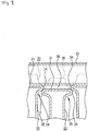
Patent document 1 has been generally known. According to this conventional technology, plate material is folded into a corrugated shape, while, as shown inFig. 8 , the folded sections (30) formed by the folding are pressed and deformed into a recessed shape to form engagement recesses (31) such that a pipe member (32) through which fluid flows can be disposed at the engagement recesses (31). The deformation pressing of the engagement recesses (31) causes swollen sections (34) to protrude at both sides of each fin's (33) folded section (30), and in a state where a pipe member (32) is disposed at the engagement recesses (31), swollen sections (34) of neighbouring folded sections (30) are brought into linear or punctual contact with each other. - Patent document 1:
JP 2005 201622 A - However, although in accordance with the
above Patent document 1 swollen sections (34) are formed at the engagement recesses (31) formed in the folded section (30) of every fin (33), when a pipe member (32) is assembled onto the fin member (35) and a pressing force in axial direction of the pipe member (32) is applied to the fins (33), the swollen sections (34) of the respective fins (33) make point-shaped or line-shaped contact with each other. Therefore, the mutual contact of the swollen sections (34) becomes unstable, such that at the time of said assembly situations may easily arise where the contacting portions of swollen sections (34) slip in radial direction of the pipe member (32) or, as shown inFig. 8 , one of two contacting swollen sections (34) rides over the other. - When in this way slippage in radial direction of the pipe member (32) or ride-over occur at the contacting portions of the swollen sections (34), the fin member (35) deforms irregularly such that the engagement recesses (31) can no longer be kept on the same arc surface, and it becomes difficult to stably mount the pipe member (32) onto the engagement recesses (31) of the fin member (35). Moreover, as to those portions where slippage in radial direction of the pipe member (32) or ride-over have occurred, non-contacting portions (36) arise between the engagement recesses (31) and the circumferential surface of the pipe member (32) that make it difficult to bring both into contact, causing the heat conducting area to diminish and bringing about a danger of decreasing heat exchange performance. Furthermore, at the non-contacting portions (36) dirt, sediments and the like are liable to build up, promoting the occurrence of corrosion of the fin member (35) and the pipe member (32). Also, because as explained above the swollen sections (34) of the fins (33) are able to be brought into mutual contact in point-shaped or line-shaped fashion only, the contact area between the folded sections (30) of the fins (33) also becomes small in comparison to a case where the swollen sections (34) are brought into surface contact with each other. This leads to a lack in stability of the shape of the fins (33) and the overall shape of the fin member (35), together with the thermal conduction between the folded sections (30) becoming unstable such that the heat exchange performance is liable to drop.
- The present invention attempts to solve the above-mentioned problems, by stabilising the mutual contact between the swollen sections of the fins to prevent ride-over and slippage in radial direction of the pipe member from occurring at the contacting portions of the fins, such that when, in order to make every contacting portion of the fin member adhere reliably, a sufficient pressing force is exerted on the pipe member and the fin member, irregular deformation of the fin member is suppressed and stable mounting of a pipe member to the fin member enabled, while preventing the contact area of the fin member and the pipe member as well as the mutual contact area of the folded section of the fins from diminishing to improve heat exchange performance. Moreover, it aims at preventing corrosion of the fin member and pipe member due to adherence of dirt, sediments and the like for improved durability.
- According to the invention of the present application, in order to solve the above-mentioned problems, a plate material is repeatedly folded over itself into a corrugated shape to form corrugated fins. The folded sections, which are formed by the folding, are deformed by pressing into a recessed shape to form engagement recesses. A pipe member for passing a fluid therethrough is engagingly disposable at the engagement recesses. The deformation by pressing of the engagement recesses cause swollen sections to protrude at both sides of each folded section with respect to the folding-over direction of the folded section and form flat butt surfaces at the tips of the swollen sections, such that adjacent butt surfaces are caused to be in surface contact with each other when a pipe member is disposed at the engagement recesses.
- Furthermore, the butt surfaces may be formed to become perpendicular to a pipe axis direction of a pipe member engagingly disposed on the fin member. Due to the formation in this way, when neighbouring butt surfaces are brought into surface contact, the contact surface become disposed perpendicular to the the pipe axis direction of the pipe member. Therefore, even if a large pressing force is applied in axial direction of the fin member during mounting of a pipe member to the fin member, this large pressing force will act perpendicularly on the reciprocal contact surfaces of the butt surfaces such that the occurrence of a force in radial direction of the pipe member is enabled to be suppressed all the more efficiently, and at the portions of mutual contact between the butt surfaces slippage in radial direction of the pipe member will not occur. Therefore, it becomes possible to press the fin member with said large pressing force to increase the contact surface pressure between the butt surfaces, thus enlarging the thermally conducting area for further improvement of the heat exchange performance.
- Moreover, the cross-sectional contour shape of the engagement recesses may be an arc shape, an oval shape, an elliptical shape, or similar shape matched to the cross-sectional contour shape of the pipe member.
- Because according to the present invention, as mentioned above, flat butt surfaces are provided at the tip of each swollen section in preferably perpendicular orientation to the central axis of the pipe member to be engaged, when assembling the pipe member with the fin member, even if each part is pressed with a strong pressing force in order to increase the contact surface pressure at all areas of contact between the pipe member and fin member, it becomes possible to bring the flat butt surfaces of neighbouring fins into surface contact with each other while hindering the occurrence of forces in radial direction of the pipe member between the contact surfaces. Therefore, compared to a case where the swollen sections are mutually brought into linear or punctual contact, forces in radial direction of the pipe member are more difficult to occur, assembly is enabled to be stabilised, and ride-over as well as slippage in radial direction of the pipe member are enabled to be inhibited even when a pressing force in the folding-over direction of the fins acts on the contacting portions of the swollen sections. Therefore, because the engagement recesses formed in the fin member are enabled to be kept on the same arc surface, the pipe member is enabled to be stably engaged and assembled with the fin member, and the circumferential surface of the pipe member is enabled to be brought by strong surface pressure into reliable surface contact with all engagement recesses formed in the fin member, such that it becomes possible to increase the area of thermal conduction for improved heat exchange performance.
- Moreover, because by preventing, as described above, ride-over and slippage in radial direction of the pipe member from occurring at the contacting portions of the swollen sections to thereby maintain all engagement recesses of the fin member on the same arc surface, all engagement recesses of the fin member are enabled to be brought into reliable surface contact with the circumferential surface of the pipe member to make intervening gaps disappear or become extremely small, it becomes possible to prevent the fin member and pipe member from corroding due to intrusion of dirt, sediments and the like, such that also corrosion resistance and longevity are enabled to be simultaneously achieved.
-
- [
Fig. 1 ] Perspective view showing a fin member in accordance withEmbodiment 1. - [
Fig. 2 ] Cross-sectional view along line A-A inFig. 1 . - [
Fig. 3 ] Side view of the fin member. - [
Fig. 4 ] Top view of the fin member. - [
Fig. 5 ] Perspective view showing the fin member with a top die and a bottom die for forming engagement recesses and butt surfaces. - [
Fig. 6 ] Cross-sectional view showing the process of forming the engagement recesses and butt surfaces in the fin member. - [
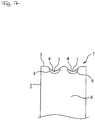
Fig. 7 ] Side view of a fin member in accordance withEmbodiment 2. - [
Fig. 8 ] Cross-sectional view showing an example of a conventional fin member in a state where swollen sections have ridden over each other. - To explain
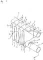
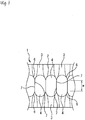
Embodiment 1 of the invention on the basis ofFigs. 1 to 6 , (1) is a fin member formed, as shown inFig. 1 , by successively subjecting a belt-shaped plate material to repeated alternate folding into a corrugated shape to stack up a plurality of fins (2) composed of flat sections (9) and folded sections (3). In the fin member (1), the apex of each folded section (3) formed by the above folding is deformed into a recessed shape by pressing inwardly in direction perpendicular to the stacking direction of the plurality of fins (2) to form corresponding engagement recesses (4) at the apex of each folded section (3), thereby enabling a pipe member (5) for passing a fluid, as shown inFigs. 1 and2 , to be engagingly arranged within an arc-shaped surface formed by the engagement recesses (4). Furthermore, it sometimes may occur that the flat sections (9) become slightly distorted due to external forces acting at the time of folding, the time of engagingly arranging the pipe member (5) onto the fin member (1) etc. and in consequence are unable to present a perfectly flat surface. - Moreover, in the fin member (1), as shown in
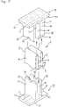
Fig. 2 , along with the forming of the engagement recesses (4), swollen sections (6) are induced to protrude from the folded sections (3) toward both sides in stacking direction. At the tip of the swollen sections (6), as shown inFig. 4 , substantially crescent-shaped flat butt surfaces (7) are formed perpendicular to the axial direction of the pipe member (5), i.e. the stacking direction of the fins (2). In the present embodiment, by making use of a top die (8) and a bottom die (10), deformation pressing of the engagement recesses (4) is performed that incorporates formation of the butt surfaces (7). The top die (8) and the bottom die (10), as shown inFig. 5 , are composed of a base section (13) with protrusions (11) of semicircular cross-sectional shape formed protruding in-line from one side (12), and of protruding walls (15) formed protruding perpendicularly to the central axis of the protrusions (11) at uniform intervening spacing (14) from said one side (12) of the base section (13). On the protruding walls (15), at the centre of the end thereof, respective arc-shaped channels (16) are formed, which are matched to the protrusions (11) such that the curvature radii differ by the plate thickness dimension. In a state when the top die (8) and the bottom die (10) are combined as shown inFig. 6 , the protrusions (11) of the top die (8) and the channels (16) of respective protruding walls (15) of the bottom die (10), as well as the protrusions (11) of the bottom die (10) and the channels (16) of respective protruding walls (15) of the top die (8), are enabled to engage each other. - Then, as indicated by arrows in
Fig. 5 , the fins (2) of the fin member (1) are arranged within the spacing (14) of the protruding walls (15) of the bottom die (10) and the top die (8), the folded sections (3) of the fins (2) being arranged individually between the protrusions (11) of the top die (8) and the channels (16) of the protruding walls (15) of the bottom die (10), as well as between the protrusions (11) of the bottom die (10) and the engagement recesses (4) of the protruding walls (15) of the top die (8). In this state, as shown inFig. 6 , the top die (8) and the bottom die (10) are pushed against each other. In consequence, the folded sections (3) of the fins (2), which are sandwiched between the protrusions (11) of the top die (8) and the channels (16) of the protruding walls (15) of the bottom die (10) as well as between the protrusions (11) of the bottom die (10) and the channels (16) of the protruding walls (15) of the top die (8), deform along the curved shape of the protrusions (11) and channels (16) such that, as shown inFigs. 1 to 4 , the engagement recesses (4) at the folded sections (3) of the fin member (1) are formed. - Moreover, when in this way press-deforming the apices of the folded sections (3) inwardly in direction perpendicular to the stacking direction of the fins (2), in co-occurrence with the same, as shown in
Fig. 6 , the swollen sections (6) protrude from the folding sections (3) toward both sides in stacking direction, such that the tips of the swollen sections (6) hit against the flat wall surfaces (17) of the protruding walls (15) of the top die (8) and the bottom die (10), which are perpendicular to the stacking direction of the fins (2), to respectively form the flat butt surfaces (7) at the tip of each swollen section (6). By employing a top die (8) and a bottom die (10) in this way, the present embodiment enables to perform the process of forming the engagement recesses (4) at each fin (2) of the fin member (1) simultaneously with the process of forming the flat butt surfaces (7) perpendicular to the stacking direction of the fins (2) at each swollen section (6), thus enabling to achieve process speedup and optimisation. - Moreover, the forming of flat butt surfaces (7) in this way at the tip of each swollen section (6) enables, as shown in
Fig. 2 , to bring the flat butt surfaces (7) of neighbouring fins (2) into surface contact with each other when assembling a pipe member (5) with the fin member (1), even if each part is pressed with a strong pressing force in order to increase the contact surface pressure at all areas of contact between the pipe member (5) and fin member (1), while hindering the occurrence of forces in radial direction of the pipe member (5) between the contact surfaces. Therefore, compared to a case where the swollen sections (6) are mutually brought into linear or punctual contact, forces in radial direction of the pipe member (5) are more difficult to occur, assembly is enabled to be stabilised, and ride-over as well as slippage in radial direction of the pipe member (5) are enabled to be inhibited even when a pressing force in the stacking direction of the fins (2) acts on the contacting portions of the swollen sections (6). Therefore, because the engagement recesses (4) formed in the fin member (1) are enabled to be kept on the same arc surface, the pipe member (5) is enabled to be stably engaged and assembled with the fin member (1), and the circumferential surface of the pipe member (5) is enabled to be brought by strong surface pressure into reliable surface contact with all engagement recesses (4) formed in the fin member (1), such that it becomes possible to increase the area of thermal conduction for improved heat exchange performance. - Moreover, because by preventing, as described above, ride-over and slippage in radial direction of the pipe member (5) from occurring at the contacting portions of the swollen sections (6) to thereby maintain all engagement recesses (4) of the fin member (1) on the same arc surface, all engagement recesses (4) of the fin member (1) are enabled to be brought into reliable surface contact with the circumferential surface of the pipe member (5) to make intervening gaps disappear or become extremely small, it becomes possible to prevent the fin member (1) and pipe member (5) from corroding due to intrusion of dirt, sediments and the like, such that also corrosion resistance and longevity are enabled to be simultaneously achieved.
- Moreover, because by bringing, as described above, the flat butt surfaces (7) formed in swollen sections (6) of neighbouring folded sections (3) of the fin member (1) into reliable surface contact with each other, the area of contact between adjacent fin members (1) is enabled to be increased in comparison to a case where the butt surfaces (7) are brought into linear or punctual contact, such that also in this respect heat exchange performance is enabled to be improved.
- Moreover, because in the present embodiment the butt surfaces (7) of each fin (2) of the fin member (1) are formed to become perpendicular to the pipe axis direction of a pipe member (5) that is to be assembled with the fin member (1), as shown in
Figs. 3 and4 , when the butt surfaces (7) mutually are brought into surface contact, their contacting surfaces will be disposed perpendicular to the pipe axis direction of the pipe member (5). Therefore, even if a large pressing force is applied in axial direction of the fin member (1) during attachment of a pipe member (5) to the fin member (1), this large pressing force will act perpendicularly to the surfaces of mutual contact of the butt surfaces (7) such that the occurrence of a force in radial direction of the pipe member (5) is enabled to be suppressed all the more efficiently, and at the portions of mutual contact between the butt surfaces (7) slippage in radial direction of the pipe member (5) will not occur. Therefore, it becomes possible to press the fin member (1) with said large pressing force to increase the contact surface pressure between the butt surfaces (7), thus enlarging the thermally conducting area for further improvement of the heat exchange performance. - Preferably, the butt surfaces (7) are formed with a height of 0.5 mm to 2.5 mm, and a width of 4.5 mm to 6.5 mm. Further, in the present description the "height" of a flat butt surface (7), as indicated by the arrows h in
Fig. 3 , refers to the distance from the top to the bottom of the butt surface (7), whereas the "width" of the butt surface, as indicated by the arrows w inFigs. 3 and4 , refers to the distance from one tip to the other. If the height of the butt surfaces (7) is less than 0.5 mm or the width of the butt surfaces (7) is less than 4.5 mm, contact between the butt surfaces (7) will be insufficient when the butt surfaces (7) are brought into contact with each other, such that it may easily happen that the swollen section (6) on one side will ride over the swollen section (6) on the other side, or that a slippage in radial direction of the pipe member (5) will occur at the position of contact. And, if the height of the butt surfaces (7) is made greater than 2.5 mm or the width of the butt surfaces (7) is made greater than 6.5 mm, the formation width, formation depth etc. of the engagement recesses (4) have to be made undesirably large, risking to cause cracks to appear at the engagement recesses (4) of the fin member (1), particularly in the vicinity of the rim of the butt surfaces (7). - Whereas in
above Embodiment 1, as shown inFig. 1 , engagement recesses (4) were provided one-by-one at each folded section (3) of the fin member (1), in thepresent Embodiment 2, as shown inFig. 7 , two engagement recesses (4) are formed at each folded section (3), spaced apart in the width direction of the folded section (3). Because the present embodiment enables, by forming more than one engagement recess (4) per folded section (3), to arrange a plurality of pipe members (5) on one fin member (1), the contact area between the fin member (1) and the pipe members (5) is enlarged in comparison to a case where only one pipe member (5) is arranged on one fin member (1), thereby enabling to achieve an improved heat exchange performance. However, in case that a plurality of engagement recesses (4) is formed per folded section (3) as in the present embodiment, when the formation spacing of the individual engagement recesses (4) is made too narrow there is a risk that neighbouring swollen sections (6) will interfere with each other, such that the swelling of the swollen sections (6) is suppressed, and the formation of the butt surfaces (7) cannot be sufficiently performed. - In
present Embodiment 2 and aboveEmbodiment 1, cases have been explained where engagement recesses (4) of arc-shaped cross-sectional contour shape are formed in the fin member (1). However, in other different embodiments it is also possible to make the cross-sectional contour shape of the engagement recesses (4) an arbitrary shape such as an oval shape or elliptic shape that matches a cross-sectional shape of the pipe member (5). -
- 3
- folded section
- 4
- engagement recess
- 5
- pipe member
- 6
- swollen section
- 7
- butt surface
Claims (3)
- A fin member (1) for a heat exchanger, comprising corrugated fins (2) formed by repeatedly folding a plate material over itself into a corrugated shape, wherein folded sections (3) formed by the folding are deformed by pressing into a recessed shape to form engagement recesses (4) for engagingly disposing a pipe member (32) for carrying a fluid at the engagement recesses (4), wherein the deformation by pressing of the engagement recesses (4) has caused swollen sections (6) to protrude at both sides of each folded section (3) with respect to the folding-over direction of the folded section (3)
characterized in that flat butt surfaces (7) are formed at the tips of the swollen sections (6), such that adjacent butt surfaces can be brought into surface contact with each other in a state when a pipe member (5) is disposed at the engagement recesses. - The fin member (1) for a heat exchanger according to claim 1, wherein the butt surfaces (7) are formed to become perpendicular to a stacking direction of the fins.
- The fin member (1) for a heat exchanger according to claim 1, wherein the engagement recesses (4) comprise an arc-shaped, ovally shaped, or elliptically shaped cross-sectional contour shape.
Applications Claiming Priority (2)
| Application Number | Priority Date | Filing Date | Title |
|---|---|---|---|
| JP2009254191A JP5495720B2 (en) | 2009-11-05 | 2009-11-05 | Fin member for heat exchanger |
| PCT/JP2010/006366 WO2011055515A1 (en) | 2009-11-05 | 2010-10-28 | Fin member for heat exchanger |
Publications (3)
| Publication Number | Publication Date |
|---|---|
| EP2498038A1 EP2498038A1 (en) | 2012-09-12 |
| EP2498038A4 EP2498038A4 (en) | 2015-03-04 |
| EP2498038B1 true EP2498038B1 (en) | 2016-12-21 |
Family
ID=43969758
Family Applications (1)
| Application Number | Title | Priority Date | Filing Date |
|---|---|---|---|
| EP10828076.9A Active EP2498038B1 (en) | 2009-11-05 | 2010-10-28 | Fin member for heat exchanger |
Country Status (4)
| Country | Link |
|---|---|
| US (1) | US9097472B2 (en) |
| EP (1) | EP2498038B1 (en) |
| JP (1) | JP5495720B2 (en) |
| WO (1) | WO2011055515A1 (en) |
Families Citing this family (12)
| Publication number | Priority date | Publication date | Assignee | Title |
|---|---|---|---|---|
| US20140318753A1 (en) | 2013-04-29 | 2014-10-30 | Ford Global Technologies, Llc | Heat exchanger |
| DE202011050322U1 (en) * | 2011-06-01 | 2012-09-03 | Caradon Stelrad B.V. | Roll formed convector sheet |
| PL221028B1 (en) | 2011-06-24 | 2016-02-29 | Aic Spółka Akcyjna | Pipeline package of the heat exchanger |
| KR101402674B1 (en) * | 2012-10-31 | 2014-06-09 | (주) 비지오텍코리아 | Spiral condenser for heating and air conditioning device |
| PL222892B1 (en) | 2012-12-12 | 2016-09-30 | Aic Spółka Z Ograniczoną Odpowiedzialnością | Method for developing the surface of the heat exchange in the heat exchanger and the heat exchanger package with the heat-exchange surface |
| KR102218301B1 (en) | 2013-07-30 | 2021-02-22 | 삼성전자주식회사 | Heat exchanger and corrugated fin thereof |
| JP6276539B2 (en) * | 2013-08-26 | 2018-02-07 | 三菱重工業株式会社 | HEAT EXCHANGER AND HEAT EXCHANGER MANUFACTURING METHOD |
| KR102122256B1 (en) * | 2013-12-24 | 2020-06-12 | 엘지전자 주식회사 | Heat Exchanger |
| KR101566546B1 (en) * | 2014-05-19 | 2015-11-05 | 군산대학교산학협력단 | Louver fin type heat exchanger |
| CN106871691A (en) * | 2015-12-10 | 2017-06-20 | 爱克奇换热技术(太仓)有限公司 | Heat exchanger |
| CN109297344B (en) * | 2017-07-24 | 2021-09-03 | 爱克奇换热技术(太仓)有限公司 | Sheet, method and apparatus for manufacturing sheet, and heat exchanger |
| CN114777549B (en) * | 2022-06-20 | 2022-09-20 | 甘肃蓝科石化高新装备股份有限公司 | Finned tube with tube-fin bridge for gas to flow in different regions |
Family Cites Families (7)
| Publication number | Priority date | Publication date | Assignee | Title |
|---|---|---|---|---|
| JPS55175797U (en) * | 1979-05-30 | 1980-12-17 | ||
| JPH01181092A (en) * | 1988-01-14 | 1989-07-19 | Nippon Denso Co Ltd | Heat exchanger |
| JP2000220982A (en) * | 1999-01-27 | 2000-08-08 | Zexel Corp | Heat exchanger |
| DE50207354D1 (en) * | 2001-04-28 | 2006-08-10 | Behr Gmbh & Co Kg | Folded multi-chamber flat tube |
| US6688380B2 (en) * | 2002-06-28 | 2004-02-10 | Aavid Thermally, Llc | Corrugated fin heat exchanger and method of manufacture |
| JP2004333023A (en) * | 2003-05-08 | 2004-11-25 | Toyo Radiator Co Ltd | Flat tube for aluminum heat exchanger |
| JP4520774B2 (en) * | 2003-12-15 | 2010-08-11 | 臼井国際産業株式会社 | Heat exchanger |
-
2009
- 2009-11-05 JP JP2009254191A patent/JP5495720B2/en active Active
-
2010
- 2010-10-28 EP EP10828076.9A patent/EP2498038B1/en active Active
- 2010-10-28 WO PCT/JP2010/006366 patent/WO2011055515A1/en active Application Filing
- 2010-10-28 US US13/508,499 patent/US9097472B2/en active Active
Non-Patent Citations (1)
| Title |
|---|
| None * |
Also Published As
| Publication number | Publication date |
|---|---|
| WO2011055515A1 (en) | 2011-05-12 |
| US9097472B2 (en) | 2015-08-04 |
| US20120273182A1 (en) | 2012-11-01 |
| JP5495720B2 (en) | 2014-05-21 |
| EP2498038A4 (en) | 2015-03-04 |
| EP2498038A1 (en) | 2012-09-12 |
| JP2011099610A (en) | 2011-05-19 |
Similar Documents
| Publication | Publication Date | Title |
|---|---|---|
| EP2498038B1 (en) | Fin member for heat exchanger | |
| US8516699B2 (en) | Method of manufacturing a heat exchanger having a contoured insert | |
| US9395121B2 (en) | Heat exchanger having convoluted fin end and method of assembling the same | |
| JP3998938B2 (en) | Heat exchanger and manufacturing method thereof | |
| US6729389B2 (en) | Heat transfer apparatus with zigzag passage | |
| US8235098B2 (en) | Heat exchanger flat tube with oblique elongate dimples | |
| US7621317B2 (en) | Self-breaking radiator side plates | |
| US5482115A (en) | Heat exchanger and plate fin therefor | |
| US10436156B2 (en) | Air fin for a heat exchanger, and method of making the same | |
| US20070012425A1 (en) | Heat exchanger | |
| JP2007139376A (en) | Heat exchanger | |
| JP4681139B2 (en) | Heat transfer tube, method for manufacturing the same, multi-tube heat exchanger using the heat transfer tube, and radiator built-in oil cooler | |
| JP2009192174A (en) | Manufacturing method of heat exchanger, and heat exchanger | |
| WO2008047827A1 (en) | Heat exchanger tube and method of producing the same | |
| US20110203782A1 (en) | Heat exchanger fins, assemblies and methods | |
| KR20140020702A (en) | Heat exchanger tube, heat exchanger tube assembly, and methods of making the same | |
| US20070255213A1 (en) | Tube and method of producing the same | |
| EP2583030B1 (en) | Tube in fire tube boiler | |
| JP2002350071A (en) | Double pipe heat exchanger | |
| JP2005049007A (en) | Heat exchanger tube having embedded fin member | |
| JP4256217B2 (en) | Heat transfer tube | |
| WO2006055916A2 (en) | Heat exchanger tube and method of making | |
| JP4506435B2 (en) | Heat exchanger | |
| JP2007327690A (en) | Piping body for heat exchange | |
| JP2002318093A (en) | Heat exchanger |
Legal Events
| Date | Code | Title | Description |
|---|---|---|---|
| PUAI | Public reference made under article 153(3) epc to a published international application that has entered the european phase |
Free format text: ORIGINAL CODE: 0009012 |
|
| 17P | Request for examination filed |
Effective date: 20120510 |
|
| AK | Designated contracting states |
Kind code of ref document: A1 Designated state(s): AL AT BE BG CH CY CZ DE DK EE ES FI FR GB GR HR HU IE IS IT LI LT LU LV MC MK MT NL NO PL PT RO RS SE SI SK SM TR |
|
| DAX | Request for extension of the european patent (deleted) | ||
| A4 | Supplementary search report drawn up and despatched |
Effective date: 20150129 |
|
| RIC1 | Information provided on ipc code assigned before grant |
Ipc: B21D 53/02 20060101ALI20150123BHEP Ipc: F28F 1/30 20060101AFI20150123BHEP Ipc: F28F 1/12 20060101ALI20150123BHEP Ipc: F28F 1/32 20060101ALI20150123BHEP Ipc: F28F 13/12 20060101ALI20150123BHEP |
|
| GRAP | Despatch of communication of intention to grant a patent |
Free format text: ORIGINAL CODE: EPIDOSNIGR1 |
|
| RIC1 | Information provided on ipc code assigned before grant |
Ipc: F28F 13/12 20060101ALI20160615BHEP Ipc: F28F 1/30 20060101AFI20160615BHEP Ipc: F28F 1/12 20060101ALI20160615BHEP Ipc: F28F 1/32 20060101ALI20160615BHEP Ipc: B21D 53/02 20060101ALI20160615BHEP |
|
| INTG | Intention to grant announced |
Effective date: 20160721 |
|
| STAA | Information on the status of an ep patent application or granted ep patent |
Free format text: STATUS: GRANT OF PATENT IS INTENDED |
|
| GRAS | Grant fee paid |
Free format text: ORIGINAL CODE: EPIDOSNIGR3 |
|
| GRAA | (expected) grant |
Free format text: ORIGINAL CODE: 0009210 |
|
| STAA | Information on the status of an ep patent application or granted ep patent |
Free format text: STATUS: THE PATENT HAS BEEN GRANTED |
|
| AK | Designated contracting states |
Kind code of ref document: B1 Designated state(s): AL AT BE BG CH CY CZ DE DK EE ES FI FR GB GR HR HU IE IS IT LI LT LU LV MC MK MT NL NO PL PT RO RS SE SI SK SM TR |
|
| REG | Reference to a national code |
Ref country code: GB Ref legal event code: FG4D |
|
| REG | Reference to a national code |
Ref country code: CH Ref legal event code: EP |
|
| REG | Reference to a national code |
Ref country code: IE Ref legal event code: FG4D |
|
| REG | Reference to a national code |
Ref country code: AT Ref legal event code: REF Ref document number: 855855 Country of ref document: AT Kind code of ref document: T Effective date: 20170115 |
|
| REG | Reference to a national code |
Ref country code: DE Ref legal event code: R096 Ref document number: 602010039054 Country of ref document: DE |
|
| PG25 | Lapsed in a contracting state [announced via postgrant information from national office to epo] |
Ref country code: LV Free format text: LAPSE BECAUSE OF FAILURE TO SUBMIT A TRANSLATION OF THE DESCRIPTION OR TO PAY THE FEE WITHIN THE PRESCRIBED TIME-LIMIT Effective date: 20161221 |
|
| REG | Reference to a national code |
Ref country code: LT Ref legal event code: MG4D |
|
| REG | Reference to a national code |
Ref country code: NL Ref legal event code: MP Effective date: 20161221 |
|
| PG25 | Lapsed in a contracting state [announced via postgrant information from national office to epo] |
Ref country code: SE Free format text: LAPSE BECAUSE OF FAILURE TO SUBMIT A TRANSLATION OF THE DESCRIPTION OR TO PAY THE FEE WITHIN THE PRESCRIBED TIME-LIMIT Effective date: 20161221 Ref country code: NO Free format text: LAPSE BECAUSE OF FAILURE TO SUBMIT A TRANSLATION OF THE DESCRIPTION OR TO PAY THE FEE WITHIN THE PRESCRIBED TIME-LIMIT Effective date: 20170321 Ref country code: LT Free format text: LAPSE BECAUSE OF FAILURE TO SUBMIT A TRANSLATION OF THE DESCRIPTION OR TO PAY THE FEE WITHIN THE PRESCRIBED TIME-LIMIT Effective date: 20161221 Ref country code: GR Free format text: LAPSE BECAUSE OF FAILURE TO SUBMIT A TRANSLATION OF THE DESCRIPTION OR TO PAY THE FEE WITHIN THE PRESCRIBED TIME-LIMIT Effective date: 20170322 |
|
| REG | Reference to a national code |
Ref country code: AT Ref legal event code: MK05 Ref document number: 855855 Country of ref document: AT Kind code of ref document: T Effective date: 20161221 |
|
| PG25 | Lapsed in a contracting state [announced via postgrant information from national office to epo] |
Ref country code: FI Free format text: LAPSE BECAUSE OF FAILURE TO SUBMIT A TRANSLATION OF THE DESCRIPTION OR TO PAY THE FEE WITHIN THE PRESCRIBED TIME-LIMIT Effective date: 20161221 Ref country code: RS Free format text: LAPSE BECAUSE OF FAILURE TO SUBMIT A TRANSLATION OF THE DESCRIPTION OR TO PAY THE FEE WITHIN THE PRESCRIBED TIME-LIMIT Effective date: 20161221 Ref country code: HR Free format text: LAPSE BECAUSE OF FAILURE TO SUBMIT A TRANSLATION OF THE DESCRIPTION OR TO PAY THE FEE WITHIN THE PRESCRIBED TIME-LIMIT Effective date: 20161221 |
|
| PG25 | Lapsed in a contracting state [announced via postgrant information from national office to epo] |
Ref country code: NL Free format text: LAPSE BECAUSE OF FAILURE TO SUBMIT A TRANSLATION OF THE DESCRIPTION OR TO PAY THE FEE WITHIN THE PRESCRIBED TIME-LIMIT Effective date: 20161221 |
|
| PG25 | Lapsed in a contracting state [announced via postgrant information from national office to epo] |
Ref country code: IS Free format text: LAPSE BECAUSE OF FAILURE TO SUBMIT A TRANSLATION OF THE DESCRIPTION OR TO PAY THE FEE WITHIN THE PRESCRIBED TIME-LIMIT Effective date: 20170421 Ref country code: RO Free format text: LAPSE BECAUSE OF FAILURE TO SUBMIT A TRANSLATION OF THE DESCRIPTION OR TO PAY THE FEE WITHIN THE PRESCRIBED TIME-LIMIT Effective date: 20161221 Ref country code: CZ Free format text: LAPSE BECAUSE OF FAILURE TO SUBMIT A TRANSLATION OF THE DESCRIPTION OR TO PAY THE FEE WITHIN THE PRESCRIBED TIME-LIMIT Effective date: 20161221 Ref country code: EE Free format text: LAPSE BECAUSE OF FAILURE TO SUBMIT A TRANSLATION OF THE DESCRIPTION OR TO PAY THE FEE WITHIN THE PRESCRIBED TIME-LIMIT Effective date: 20161221 Ref country code: SK Free format text: LAPSE BECAUSE OF FAILURE TO SUBMIT A TRANSLATION OF THE DESCRIPTION OR TO PAY THE FEE WITHIN THE PRESCRIBED TIME-LIMIT Effective date: 20161221 |
|
| PG25 | Lapsed in a contracting state [announced via postgrant information from national office to epo] |
Ref country code: IT Free format text: LAPSE BECAUSE OF FAILURE TO SUBMIT A TRANSLATION OF THE DESCRIPTION OR TO PAY THE FEE WITHIN THE PRESCRIBED TIME-LIMIT Effective date: 20161221 Ref country code: BG Free format text: LAPSE BECAUSE OF FAILURE TO SUBMIT A TRANSLATION OF THE DESCRIPTION OR TO PAY THE FEE WITHIN THE PRESCRIBED TIME-LIMIT Effective date: 20170321 Ref country code: PL Free format text: LAPSE BECAUSE OF FAILURE TO SUBMIT A TRANSLATION OF THE DESCRIPTION OR TO PAY THE FEE WITHIN THE PRESCRIBED TIME-LIMIT Effective date: 20161221 Ref country code: AT Free format text: LAPSE BECAUSE OF FAILURE TO SUBMIT A TRANSLATION OF THE DESCRIPTION OR TO PAY THE FEE WITHIN THE PRESCRIBED TIME-LIMIT Effective date: 20161221 Ref country code: ES Free format text: LAPSE BECAUSE OF FAILURE TO SUBMIT A TRANSLATION OF THE DESCRIPTION OR TO PAY THE FEE WITHIN THE PRESCRIBED TIME-LIMIT Effective date: 20161221 Ref country code: BE Free format text: LAPSE BECAUSE OF FAILURE TO SUBMIT A TRANSLATION OF THE DESCRIPTION OR TO PAY THE FEE WITHIN THE PRESCRIBED TIME-LIMIT Effective date: 20161221 Ref country code: PT Free format text: LAPSE BECAUSE OF FAILURE TO SUBMIT A TRANSLATION OF THE DESCRIPTION OR TO PAY THE FEE WITHIN THE PRESCRIBED TIME-LIMIT Effective date: 20170421 Ref country code: SM Free format text: LAPSE BECAUSE OF FAILURE TO SUBMIT A TRANSLATION OF THE DESCRIPTION OR TO PAY THE FEE WITHIN THE PRESCRIBED TIME-LIMIT Effective date: 20161221 |
|
| REG | Reference to a national code |
Ref country code: DE Ref legal event code: R097 Ref document number: 602010039054 Country of ref document: DE |
|
| REG | Reference to a national code |
Ref country code: FR Ref legal event code: PLFP Year of fee payment: 8 |
|
| PLBE | No opposition filed within time limit |
Free format text: ORIGINAL CODE: 0009261 |
|
| STAA | Information on the status of an ep patent application or granted ep patent |
Free format text: STATUS: NO OPPOSITION FILED WITHIN TIME LIMIT |
|
| 26N | No opposition filed |
Effective date: 20170922 |
|
| PG25 | Lapsed in a contracting state [announced via postgrant information from national office to epo] |
Ref country code: DK Free format text: LAPSE BECAUSE OF FAILURE TO SUBMIT A TRANSLATION OF THE DESCRIPTION OR TO PAY THE FEE WITHIN THE PRESCRIBED TIME-LIMIT Effective date: 20161221 |
|
| PG25 | Lapsed in a contracting state [announced via postgrant information from national office to epo] |
Ref country code: SI Free format text: LAPSE BECAUSE OF FAILURE TO SUBMIT A TRANSLATION OF THE DESCRIPTION OR TO PAY THE FEE WITHIN THE PRESCRIBED TIME-LIMIT Effective date: 20161221 |
|
| PG25 | Lapsed in a contracting state [announced via postgrant information from national office to epo] |
Ref country code: MC Free format text: LAPSE BECAUSE OF FAILURE TO SUBMIT A TRANSLATION OF THE DESCRIPTION OR TO PAY THE FEE WITHIN THE PRESCRIBED TIME-LIMIT Effective date: 20161221 |
|
| REG | Reference to a national code |
Ref country code: CH Ref legal event code: PL |
|
| REG | Reference to a national code |
Ref country code: IE Ref legal event code: MM4A |
|
| PG25 | Lapsed in a contracting state [announced via postgrant information from national office to epo] |
Ref country code: CH Free format text: LAPSE BECAUSE OF NON-PAYMENT OF DUE FEES Effective date: 20171031 Ref country code: LI Free format text: LAPSE BECAUSE OF NON-PAYMENT OF DUE FEES Effective date: 20171031 Ref country code: LU Free format text: LAPSE BECAUSE OF NON-PAYMENT OF DUE FEES Effective date: 20171028 |
|
| PG25 | Lapsed in a contracting state [announced via postgrant information from national office to epo] |
Ref country code: MT Free format text: LAPSE BECAUSE OF NON-PAYMENT OF DUE FEES Effective date: 20171028 |
|
| REG | Reference to a national code |
Ref country code: FR Ref legal event code: PLFP Year of fee payment: 9 |
|
| PG25 | Lapsed in a contracting state [announced via postgrant information from national office to epo] |
Ref country code: IE Free format text: LAPSE BECAUSE OF NON-PAYMENT OF DUE FEES Effective date: 20171028 |
|
| PG25 | Lapsed in a contracting state [announced via postgrant information from national office to epo] |
Ref country code: HU Free format text: LAPSE BECAUSE OF FAILURE TO SUBMIT A TRANSLATION OF THE DESCRIPTION OR TO PAY THE FEE WITHIN THE PRESCRIBED TIME-LIMIT; INVALID AB INITIO Effective date: 20101028 |
|
| PG25 | Lapsed in a contracting state [announced via postgrant information from national office to epo] |
Ref country code: CY Free format text: LAPSE BECAUSE OF NON-PAYMENT OF DUE FEES Effective date: 20161221 |
|
| PG25 | Lapsed in a contracting state [announced via postgrant information from national office to epo] |
Ref country code: MK Free format text: LAPSE BECAUSE OF FAILURE TO SUBMIT A TRANSLATION OF THE DESCRIPTION OR TO PAY THE FEE WITHIN THE PRESCRIBED TIME-LIMIT Effective date: 20161221 |
|
| PG25 | Lapsed in a contracting state [announced via postgrant information from national office to epo] |
Ref country code: TR Free format text: LAPSE BECAUSE OF FAILURE TO SUBMIT A TRANSLATION OF THE DESCRIPTION OR TO PAY THE FEE WITHIN THE PRESCRIBED TIME-LIMIT Effective date: 20161221 |
|
| PG25 | Lapsed in a contracting state [announced via postgrant information from national office to epo] |
Ref country code: AL Free format text: LAPSE BECAUSE OF FAILURE TO SUBMIT A TRANSLATION OF THE DESCRIPTION OR TO PAY THE FEE WITHIN THE PRESCRIBED TIME-LIMIT Effective date: 20161221 |
|
| PGFP | Annual fee paid to national office [announced via postgrant information from national office to epo] |
Ref country code: GB Payment date: 20231020 Year of fee payment: 14 |
|
| PGFP | Annual fee paid to national office [announced via postgrant information from national office to epo] |
Ref country code: FR Payment date: 20231025 Year of fee payment: 14 Ref country code: DE Payment date: 20231020 Year of fee payment: 14 |