WO2011055515A1 - Fin member for heat exchanger - Google Patents
Fin member for heat exchanger Download PDFInfo
- Publication number
- WO2011055515A1 WO2011055515A1 PCT/JP2010/006366 JP2010006366W WO2011055515A1 WO 2011055515 A1 WO2011055515 A1 WO 2011055515A1 JP 2010006366 W JP2010006366 W JP 2010006366W WO 2011055515 A1 WO2011055515 A1 WO 2011055515A1
- Authority
- WO
- WIPO (PCT)
- Prior art keywords
- contact
- fin
- fin member
- pipe member
- fins
- Prior art date
Links
Images


Classifications
-
- F—MECHANICAL ENGINEERING; LIGHTING; HEATING; WEAPONS; BLASTING
- F28—HEAT EXCHANGE IN GENERAL
- F28F—DETAILS OF HEAT-EXCHANGE AND HEAT-TRANSFER APPARATUS, OF GENERAL APPLICATION
- F28F13/00—Arrangements for modifying heat-transfer, e.g. increasing, decreasing
- F28F13/06—Arrangements for modifying heat-transfer, e.g. increasing, decreasing by affecting the pattern of flow of the heat-exchange media
- F28F13/12—Arrangements for modifying heat-transfer, e.g. increasing, decreasing by affecting the pattern of flow of the heat-exchange media by creating turbulence, e.g. by stirring, by increasing the force of circulation
-
- B—PERFORMING OPERATIONS; TRANSPORTING
- B21—MECHANICAL METAL-WORKING WITHOUT ESSENTIALLY REMOVING MATERIAL; PUNCHING METAL
- B21D—WORKING OR PROCESSING OF SHEET METAL OR METAL TUBES, RODS OR PROFILES WITHOUT ESSENTIALLY REMOVING MATERIAL; PUNCHING METAL
- B21D53/00—Making other particular articles
- B21D53/02—Making other particular articles heat exchangers or parts thereof, e.g. radiators, condensers fins, headers
- B21D53/022—Making the fins
-
- F—MECHANICAL ENGINEERING; LIGHTING; HEATING; WEAPONS; BLASTING
- F28—HEAT EXCHANGE IN GENERAL
- F28F—DETAILS OF HEAT-EXCHANGE AND HEAT-TRANSFER APPARATUS, OF GENERAL APPLICATION
- F28F1/00—Tubular elements; Assemblies of tubular elements
- F28F1/10—Tubular elements and assemblies thereof with means for increasing heat-transfer area, e.g. with fins, with projections, with recesses
- F28F1/12—Tubular elements and assemblies thereof with means for increasing heat-transfer area, e.g. with fins, with projections, with recesses the means being only outside the tubular element
- F28F1/126—Tubular elements and assemblies thereof with means for increasing heat-transfer area, e.g. with fins, with projections, with recesses the means being only outside the tubular element consisting of zig-zag shaped fins
-
- B—PERFORMING OPERATIONS; TRANSPORTING
- B21—MECHANICAL METAL-WORKING WITHOUT ESSENTIALLY REMOVING MATERIAL; PUNCHING METAL
- B21D—WORKING OR PROCESSING OF SHEET METAL OR METAL TUBES, RODS OR PROFILES WITHOUT ESSENTIALLY REMOVING MATERIAL; PUNCHING METAL
- B21D53/00—Making other particular articles
- B21D53/02—Making other particular articles heat exchangers or parts thereof, e.g. radiators, condensers fins, headers
-
- F—MECHANICAL ENGINEERING; LIGHTING; HEATING; WEAPONS; BLASTING
- F28—HEAT EXCHANGE IN GENERAL
- F28F—DETAILS OF HEAT-EXCHANGE AND HEAT-TRANSFER APPARATUS, OF GENERAL APPLICATION
- F28F2215/00—Fins
-
- Y—GENERAL TAGGING OF NEW TECHNOLOGICAL DEVELOPMENTS; GENERAL TAGGING OF CROSS-SECTIONAL TECHNOLOGIES SPANNING OVER SEVERAL SECTIONS OF THE IPC; TECHNICAL SUBJECTS COVERED BY FORMER USPC CROSS-REFERENCE ART COLLECTIONS [XRACs] AND DIGESTS
- Y10—TECHNICAL SUBJECTS COVERED BY FORMER USPC
- Y10T—TECHNICAL SUBJECTS COVERED BY FORMER US CLASSIFICATION
- Y10T29/00—Metal working
- Y10T29/49—Method of mechanical manufacture
- Y10T29/4935—Heat exchanger or boiler making
- Y10T29/49377—Tube with heat transfer means
- Y10T29/49378—Finned tube
- Y10T29/4938—Common fin traverses plurality of tubes
Definitions
- the present invention is used for various heat absorbing and radiating pipes such as fuel pipes and oil pipes for automobiles and general industries, EGR gas cooling devices, air conditioners that adjust the temperature and humidity of residential spaces, and other heat exchangers.
- the object relates to the fin member, and an object is to obtain a heat exchanger excellent in heat exchange performance and assembly performance.
- fin members used for various heat-absorbing and radiating pipes such as fuel pipes and oil pipes for automobiles and general industries, EGR gas cooling devices, air conditioners that adjust the temperature and humidity of residential spaces, and other heat exchangers
- Japanese Patent Application Laid-Open No. H10-228707 a known one is known.
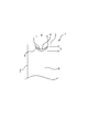
- the plate material is bent into a corrugated shape to form corrugated fins, and as shown in FIG. 8, the bent portion (30) formed by the bending process is pressed and deformed into a concave shape.
- an engagement recess (31) is formed, and a pipe member (32) through which a fluid flows is disposed in the engagement recess (31).
- the pressing deformation of the engaging recess (31) causes the bulging portion (34) to protrude on both sides of the bent portion (30) of each fin (33) and the pipe member (32 to the engaging recess (31). ) are arranged, the bulging portions (34) of the adjacent bent portions (30) are brought into line contact or point contact with each other.
- the bulging portions (34) of the fins (33) can be brought into contact with each other only in the form of dots or lines, so that the bulging portions (34) are in surface contact with each other.
- the contact area between the bent portions (30) of the fins (33) is also reduced, the stability of the shape of the fin (33) and the overall shape of the fin member (35) is lost, and the bent portions (30) are mutually connected. The heat conduction between them becomes unstable, and there is a possibility that the heat exchange performance is lowered.
- the present invention seeks to solve the above-described problems, and stabilizes the mutual contact between the bulging portions of the fins, so that the fins ride on the contact portions of the fins and the pipe members are displaced in the radial direction.
- the present invention repeatedly folds the plate material into a corrugated shape to form a corrugated fin, and presses and deforms the bent portion formed by the bending process into a concave shape.
- an engaging recess is formed, and a pipe member that circulates fluid is placed in the engaging recess, and the pressing deformation of the engaging recess bulges on both sides in the stacking direction of the bent portion.
- the protruding portion is formed, a flat abutting surface is formed at the tip of the bulging portion, and the adjacent abutting surfaces are brought into surface contact with each other in a state where the pipe member is disposed in the engaging recess.
- the abutting surface may be formed so as to be perpendicular to the tube axis direction of the tube member assembled to the fin member.
- the contact surfaces are arranged perpendicular to the tube axis direction of the tube member. Therefore, even when a large pressing force is applied in the axial direction of the fin member when the pipe member is assembled to the fin member, the large pressing force acts perpendicularly to the contact surfaces of the abutting surfaces. Since the generation of force in the radial direction can be more effectively suppressed, the pipe member is not displaced in the radial direction at the contact portions between the abutting surfaces. Therefore, it is possible to press the fin member with the large pressing force described above to increase the contact surface pressure between the abutting surfaces to increase the heat conduction area and further improve the heat exchange performance.
- the engagement concave portion may have a shape corresponding to the cross-sectional contour shape of the pipe member, such as an arc shape, an oval shape, or an elliptical shape.
- the present invention provides the flat abutting surface at the tip of the bulging portion, preferably perpendicular to the axis of the tube member to be engaged. Therefore, when assembling the tube member to the fin member, Even if each part is pressed with a large pressing force to increase the contact surface pressure of all the contact surfaces of the fin member, the flat abutting surfaces formed on the bulging portions of the adjacent bent portions of the fin member are brought into surface contact with each other. And the radial force of the pipe member is less likely to be generated between the contact surfaces.
- the radial force of the pipe member is less likely to be generated when the bulging portions formed in the bent portion are brought into contact with each other, thereby stabilizing the assembly.
- the engagement recesses formed in the fin member can be kept on the same arc surface, so that the fin member can be stably assembled to the tube member, and the engagement recesses of the fin member and the fin member and the tube can be combined.
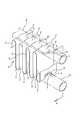
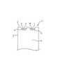
- FIG. 3 is a perspective view illustrating a fin member according to the first embodiment.
- FIG. 2 is a sectional view taken along line AA in FIG. 1.
- the side view of a fin member The top view of a fin member.
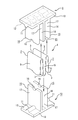
- the perspective view which shows the upper mold
- Sectional drawing which shows the process of forming an engagement recessed part and a contact surface in a fin member.
- FIG. Sectional drawing which shows the state in which the bulging part mutual riding generate
- Embodiment 1 of the present invention will be described with reference to FIGS. 1 to 6.
- (1) is a fin member, and as shown in FIG. A plurality of fins (2) constituted by the portion (9) and the bent portion (3) are stacked.
- the fin member (1) has the top of the bent portion (3) formed in each fin (2) by the bending process inward in the direction perpendicular to the stacking direction of the plurality of fins (2).
- one engaging recess (4) is formed at the top of each bent portion (3), and fluid is circulated through the arcuate surface formed by this engaging recess (4).
- the pipe member (5) to be engaged can be engaged and disposed as shown in FIGS.
- the flat plate portion (9) is slightly deformed by an external force that acts during the bending process or when the pipe member (5) is placed and engaged with the fin member (1) to form a completely flat surface. It may not be present.
- the fin member (1) projects the bulging portions (6) on both sides in the stacking direction of the bent portion (3) along with the formation of the engaging recess (4).
- a substantially crescent-shaped flat abutting surface perpendicular to the axial direction of the pipe member (5), that is, the stacking direction of the fins (2)).
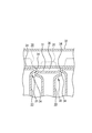
- the upper mold (8) and the lower mold (10) are used to press and deform the engaging recess (4) with the formation of the abutting surface (7).
- the upper mold (8) and the lower mold (10) include a base part (13) in which protrusions (11) having a semicircular cross section are formed in a row on one surface (12), and the base part. (13) A projecting wall (15) is formed on one surface (12) so as to project perpendicularly to the axial center of the ridge (11) via a fixed arrangement interval (14). In the projecting wall (15), arc-shaped concave grooves (16) are formed one by one at the center of the tip of the projecting wall (15) so as to correspond to the protrusion (11) so that the radius of curvature differs by the plate thickness.
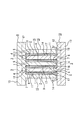
- the upper mold (8) and the lower mold (10) are combined as shown in FIG.
- the fins (2) of the fin member (1) are arranged at the arrangement interval (14) of the projecting wall (15) of the lower mold (10) and the upper mold (8),
- the bent portion (3) of each fin (2) is inserted between the protrusion (11) of the upper die (8) and the groove (16) of the protruding wall (15) of the lower die (10), and the lower die. It arrange
- the upper die (8) and the lower die (10) are brought into contact with each other.
- the bulging portion (6) protrudes on both sides in the stacking direction, and the tip of the bulging portion (6) is the fin (2) of the protruding wall (15) of the upper die (8) and the lower die (10).
- the engagement recess (4) is formed in each fin (2) of the fin member (1); Since it is possible to simultaneously perform the work of forming a flat abutting surface (7) perpendicular to the stacking direction of the fins (2) on each bulging portion (6), the work can be speeded up and made efficient. It becomes possible.
- the engagement recess (4) formed in the fin member (1) can be kept on the same arc surface, so that the fin member (1) and the pipe member (5) can be stably engaged and assembled.
- all the engagement recesses (4) formed in the fin member (1) and the outer peripheral surface of the pipe member (5) can be reliably brought into surface contact with high surface pressure, the heat conduction area is increased. Thus, the heat exchange performance can be improved.
- the abutting surfaces can be obtained by reliably bringing flat abutting surfaces (7) formed on the bulging portions (6) of the adjacent bent portions (3) of the fin member (1) into surface contact with each other. (7) Compared to the case of making line contact or point contact with each other, it becomes possible to increase the contact area between adjacent fin members (1), and also in this respect, the heat exchange performance can be improved. It becomes possible.
- the abutting surface (7) of each fin (2) of the fin member (1) is perpendicular to the tube axis direction of the tube member (5) assembled to the fin member (1).
- the contact surface is in the tube axis direction of the tube member (5).
- the abutting surface (7) is preferably formed with a vertical width of 0.5 mm to 2.5 mm and a horizontal width of 4.5 mm to 6.5 mm.
- the “vertical width” of the flat abutting surface (7) means the length from the upper end to the lower end of the abutting surface (7) as shown by the arrow h in FIG.
- the “horizontal width” for the time being means the length from one end to the other end of the abutting surface as indicated by an arrow w in FIGS. 3 and 4.
- the abutting surfaces (7) are brought into contact with each other.
- the contact between the abutment surfaces (7) becomes insufficient, and one bulging portion (6) rides on the other bulging portion (6), or a pipe member ( 5)
- the deviation in the radial direction is likely to occur.
- the formation width of the engaging recess (4), The formation depth and the like must be increased unnecessarily, and there is a risk of causing cracks and the like in the vicinity of the engaging recess (4) of the fin member (1), particularly the periphery of the abutting surface (7).
- one engagement recess (4) is provided in each bent portion (3) of the fin member (1).
- two engagement recesses (4) are formed in each bent portion (3) at intervals in the width direction of the bent portion (3).
- the cross-sectional contour shape of the engaging recess (1) it is possible to make the cross-sectional contour shape of the engaging recess (1) an arbitrary shape such as an oval or an ellipse corresponding to the cross-sectional shape of the pipe member (5).
Landscapes
- Engineering & Computer Science (AREA)
- Physics & Mathematics (AREA)
- Mechanical Engineering (AREA)
- Thermal Sciences (AREA)
- General Engineering & Computer Science (AREA)
- Geometry (AREA)
- Heat-Exchange Devices With Radiators And Conduit Assemblies (AREA)
Abstract
A fin member for a heat exchanger is configured in such a manner that swollen sections of the fins of the fin member are adapted to be in stable contact with each other to prevent the contact sections between the fins from riding over each other and also prevent a pipe member from being displaced in the radial direction. As a result of the configuration, the pipe member is stably mounted to the fin member, and this increases the area of the contact between the fin member and the pipe member and the area of the contact between folded sections of the fins to improve the heat exchange performance.
A plate material is repeatedly folded over itself into a corrugated shape to form corrugated fins. The folded sections (3) which are formed by the folding are pressed and deformed into a recessed shape to form engagement recesses (4). A pipe member (5) through which fluid flows is disposed at the engagement recesses (4). The pressing and deformation of the engagement recesses (4) cause swollen sections (6) to protrude at both sides of each folded section (3) with respect to the folding-over direction of the folded section (3) and form flat butt surfaces (7) at the tips of the swollen sections (6). Adjacent butt surfaces (7) are caused to be in surface contact with each other with the pipe member (5) disposed at the engagement recesses (4).
Description
本発明は、自動車用、一般産業用のフューエルパイプ、オイルパイプ等の各種流体の吸放熱配管、EGRガス冷却装置、居住用空間の温湿度を調整する空調機、その他の熱交換器に使用するフィン部材に係るもので、熱交換性能及び組み付け性能に優れた熱交換器を得る事を目的とするものである。
INDUSTRIAL APPLICABILITY The present invention is used for various heat absorbing and radiating pipes such as fuel pipes and oil pipes for automobiles and general industries, EGR gas cooling devices, air conditioners that adjust the temperature and humidity of residential spaces, and other heat exchangers. The object relates to the fin member, and an object is to obtain a heat exchanger excellent in heat exchange performance and assembly performance.
従来、自動車用、一般産業用のフューエルパイプ、オイルパイプ等の各種流体の吸放熱配管、EGRガス冷却装置、居住用空間の温湿度を調整する空調機、その他の熱交換器に使用するフィン部材として、特許文献1に示す如きものが公知となっている。この従来技術に於いては、板材をコルゲート状に折曲加工してコルゲートフィンとするとともに、図8に示す如く、上記折曲加工により形成される折曲部(30)を凹状に押圧変形して係合凹部(31)を形成し、この係合凹部(31)に流体を流通する管部材(32)を配置するものとしている。また、前記係合凹部(31)の押圧変形は、各フィン(33)の折曲部(30)の両側に膨出部(34)を突出させるとともに係合凹部(31)に管部材(32)を配置した状態で、隣り合う折曲部(30)の膨出部(34)相互を線接触又は点接触させるものとしている。
Conventionally, fin members used for various heat-absorbing and radiating pipes such as fuel pipes and oil pipes for automobiles and general industries, EGR gas cooling devices, air conditioners that adjust the temperature and humidity of residential spaces, and other heat exchangers As shown in Japanese Patent Application Laid-Open No. H10-228707, a known one is known. In this prior art, the plate material is bent into a corrugated shape to form corrugated fins, and as shown in FIG. 8, the bent portion (30) formed by the bending process is pressed and deformed into a concave shape. Thus, an engagement recess (31) is formed, and a pipe member (32) through which a fluid flows is disposed in the engagement recess (31). In addition, the pressing deformation of the engaging recess (31) causes the bulging portion (34) to protrude on both sides of the bent portion (30) of each fin (33) and the pipe member (32 to the engaging recess (31). ) Are arranged, the bulging portions (34) of the adjacent bent portions (30) are brought into line contact or point contact with each other.
しかしながら、上記特許文献1に於いては、各フィン(33)の折曲部(30)に形成した係合凹部(31)に膨出部(34)を形成しているものの、管部材(32)をフィン部材(35)に組み付けて、各フィン(33)に対して管部材(32)の軸方向に押圧力を作用させた時に、各フィン(33)の膨出部(34)相互が点状又は線状に接触するものとなる。そのため、膨出部(34)相互の接触が不安定なものとなり、上記組み付けの際に、膨出部(34)の接触部分が管部材(32)の径方向にズレたり、図8に示す如く、接触している2つの膨出部(34)のうちの一方が他方に乗り上げたりする事態が生じやすいものとなっていた。
However, in Patent Document 1, although the bulging portion (34) is formed in the engagement recess (31) formed in the bent portion (30) of each fin (33), the pipe member (32 ) Are attached to the fin members (35), and a pressing force is applied to the fins (33) in the axial direction of the pipe members (32). It comes in contact with dots or lines. For this reason, the mutual contact between the bulging portions (34) becomes unstable, and the contact portion of the bulging portion (34) shifts in the radial direction of the pipe member (32) during the assembly, as shown in FIG. As described above, a situation in which one of the two bulging portions (34) that are in contact with each other easily climbs over the other is likely to occur.
そして、このように膨出部(34)の接触部分に管部材(35)の径方向へのズレや乗り上げが生じると、フィン部材(35)が不規則に変形し、フィン部材(35)の複数の係合凹部(31)を同一円弧面に保つことができないものとなるため、フィン部材(35)の係合凹部(31)に管部材(32)を安定して組み付けることが困難なものとなる。また、上記の管部材(35)の径方向へのズレや乗り上げが生じた部分については、フィン部材(35)の係合凹部(31)と管部材(32)の外周面の間に非接触部(36)が生じたり、両者を面接触させることが困難なものとなったりするため、熱伝導面積が減少し、熱交換性能を低下させる虞れがある。また、上記の非接触部(36)には汚物や堆積物等が堆積しやすいものとなり、フィン部材(35)や管部材(32)に腐食を生じやすいものとなっていた。また、上述の如く、各フィン(33)の膨出部(34)相互は点状又は線状にしか接触させることができないため、膨出部(34)相互を面接触させる場合と比較して各フィン(33)の折曲部(30)相互間の接触面積も小さくなり、フィン(33)の形状、フィン部材(35)の全体形状の安定性を欠くと共に、折曲部(30)相互間の熱伝導も不安定となって、熱交換性能が低下する虞れがあった。
When the radial displacement or climbing of the pipe member (35) occurs in the contact portion of the bulging portion (34) in this way, the fin member (35) is irregularly deformed, and the fin member (35) Since the plurality of engaging recesses (31) cannot be maintained on the same arc surface, it is difficult to stably assemble the pipe member (32) to the engaging recess (31) of the fin member (35). It becomes. Further, the portion where the pipe member (35) is displaced or climbed in the radial direction is not contacted between the engaging recess (31) of the fin member (35) and the outer peripheral surface of the pipe member (32). Since the portion (36) is generated or it is difficult to bring the two into surface contact, the heat conduction area may be reduced and the heat exchange performance may be reduced. Further, filth and deposits are easily deposited on the non-contact portion (36), and the fin member (35) and the pipe member (32) are likely to be corroded. Further, as described above, the bulging portions (34) of the fins (33) can be brought into contact with each other only in the form of dots or lines, so that the bulging portions (34) are in surface contact with each other. The contact area between the bent portions (30) of the fins (33) is also reduced, the stability of the shape of the fin (33) and the overall shape of the fin member (35) is lost, and the bent portions (30) are mutually connected. The heat conduction between them becomes unstable, and there is a possibility that the heat exchange performance is lowered.
そこで、本願発明は上述の如き課題を解決しようとするものであって、各フィンの膨出部相互の接触を安定させ、各フィンの接触部分に乗り上げや管部材の径方向へのズレが発生するのを防止することにより、フィン部材の各接触部を確実に密着させるために管部材やフィン部材に対する充分な押圧力を作用させても、フィン部材の不規則な変形を抑制し、フィン部材に管部材を安定して組み付けることを可能とするとともに、フィン部材と管部材の接触面積、各フィンの折曲部相互の接触面積の減少を防止して熱交換性能を向上させようとするものである。また、汚物や堆積物等の付着によるフィン部材や管部材の腐食を防止して耐久性を向上させようとするものである。
Therefore, the present invention seeks to solve the above-described problems, and stabilizes the mutual contact between the bulging portions of the fins, so that the fins ride on the contact portions of the fins and the pipe members are displaced in the radial direction. By preventing the irregular deformation of the fin member even if a sufficient pressing force is applied to the pipe member or the fin member in order to securely contact each contact portion of the fin member, It is possible to improve the heat exchange performance by preventing the decrease of the contact area between the fin member and the tube member and the contact area between the bent parts of each fin. It is. Further, it is intended to improve durability by preventing corrosion of the fin member and the pipe member due to adhesion of dirt and deposits.
本願発明は上述の如き課題を解決するため、板材をコルゲート状に折曲加工を繰り返して重積させてコルゲートフィンとするとともに、上記折曲加工により形成される折曲部を凹状に押圧変形して係合凹部を形成し、この係合凹部に流体を流通する管部材を係合配置するものに於いて、前記係合凹部の押圧変形は、折曲部の重積方向の両側に膨出部を突出させるとともに、この膨出部の先端に平坦な突当面を形成し、係合凹部に管部材を配置した状態で、隣り合う突当面相互を面接触させるものである。
In order to solve the above-described problems, the present invention repeatedly folds the plate material into a corrugated shape to form a corrugated fin, and presses and deforms the bent portion formed by the bending process into a concave shape. In this configuration, an engaging recess is formed, and a pipe member that circulates fluid is placed in the engaging recess, and the pressing deformation of the engaging recess bulges on both sides in the stacking direction of the bent portion. The protruding portion is formed, a flat abutting surface is formed at the tip of the bulging portion, and the adjacent abutting surfaces are brought into surface contact with each other in a state where the pipe member is disposed in the engaging recess.
また、突当面は、フィン部材に組み付ける管部材の管軸方向に対して垂直となるように形成しても良い。このように形成することにより、隣り合う突当面相互を面接触させた際に、その接触面が、管部材の管軸方向に対して垂直に配置されるものとなる。そのため、フィン部材に管部材を組み付ける際に、フィン部材の軸方向に大きな押圧力を作用させたとしても、この大きな押圧力が突当面相互の接触面に対して垂直に働くものとなり、管部材の径方向に力が発生するのを一層効果的に抑制することができるため、突当面相互の接触部分に管部材の径方向へのズレが生じないものとなる。そのため、上記の大きな押圧力でフィン部材を押圧して、突当面相互の接触面圧を高めて熱伝導面積を増加させ、熱交換性能を一層向上させることが可能となる。
Further, the abutting surface may be formed so as to be perpendicular to the tube axis direction of the tube member assembled to the fin member. By forming in this way, when the adjacent abutting surfaces are brought into surface contact with each other, the contact surfaces are arranged perpendicular to the tube axis direction of the tube member. Therefore, even when a large pressing force is applied in the axial direction of the fin member when the pipe member is assembled to the fin member, the large pressing force acts perpendicularly to the contact surfaces of the abutting surfaces. Since the generation of force in the radial direction can be more effectively suppressed, the pipe member is not displaced in the radial direction at the contact portions between the abutting surfaces. Therefore, it is possible to press the fin member with the large pressing force described above to increase the contact surface pressure between the abutting surfaces to increase the heat conduction area and further improve the heat exchange performance.
また、係合凹部は、断面輪郭形状を円弧状、長円状又は楕円状などの管部材の断面輪郭形状に対応した形状のものであっても良い。
Further, the engagement concave portion may have a shape corresponding to the cross-sectional contour shape of the pipe member, such as an arc shape, an oval shape, or an elliptical shape.
本発明は上述の如く、膨出部の先端に平坦な突当面を好ましくは係合される管部材の軸心に垂直に設けているから、フィン部材に管部材を組み付ける際に、たとえ管部材とフィン部材のすべての接触面の接触面圧を高めるべく大きな押圧力で各部を押圧しても、フィン部材の隣り合う折曲部の膨出部に形成した平坦な突当面同士を面接触させることが可能となると共に接触面間に管部材の径方向の力は発生しにくくなる。そのため、膨出部同士を線接触又は点接触させる場合と比較して、折曲部に形成した膨出部同士の接触に際し管部材の径方向の力が発生しにくくなり、組付を安定させることが可能となり、膨出部の接触部分に、乗り上げや管部材の径方向へのズレが生じるのを抑制することが可能となる。そのため、フィン部材に形成した係合凹部を同一円弧面に保つことができるから、フィン部材を管部材に安定して組み付けることが可能となるとともに、フィン部材の係合凹部相互及びフィン部材と管部材の外周面を高い面圧で面接触させることにより各接触部での熱伝導面積を増加させ、熱交換性能を向上させることが可能となる。
As described above, the present invention provides the flat abutting surface at the tip of the bulging portion, preferably perpendicular to the axis of the tube member to be engaged. Therefore, when assembling the tube member to the fin member, Even if each part is pressed with a large pressing force to increase the contact surface pressure of all the contact surfaces of the fin member, the flat abutting surfaces formed on the bulging portions of the adjacent bent portions of the fin member are brought into surface contact with each other. And the radial force of the pipe member is less likely to be generated between the contact surfaces. Therefore, compared to the case where the bulging portions are brought into line contact or point contact, the radial force of the pipe member is less likely to be generated when the bulging portions formed in the bent portion are brought into contact with each other, thereby stabilizing the assembly. Thus, it is possible to prevent the bulging part from contacting and getting out of the pipe member in the radial direction. For this reason, the engagement recesses formed in the fin member can be kept on the same arc surface, so that the fin member can be stably assembled to the tube member, and the engagement recesses of the fin member and the fin member and the tube can be combined. By bringing the outer peripheral surface of the member into surface contact with high surface pressure, it is possible to increase the heat conduction area at each contact portion and improve the heat exchange performance.
また、前述の如く、膨出部の接触部分に乗り上げや管部材の径方向へのズレが生じるのを抑制し、フィン部材の係合凹部を同一円弧面(管部材が楕円管であれば同一楕円面)に保つことにより、フィン部材の係合凹部と管部材の外周面を確実に面接触させ、両者間に隙間を発生させないか極めて小さくすることが可能となる。そのため、フィン部材と管部材の隙間に汚物や堆積物等が入り込んで、フィン部材及び管部材が腐食するのを抑制することが可能となり、耐食性が向上し、長寿命化を同時に図ることも可能となる。
Further, as described above, it is possible to suppress the occurrence of climbing on the contact portion of the bulging portion and the radial displacement of the pipe member, and to make the engaging recess of the fin member have the same arc surface (the same if the pipe member is an elliptic tube). By maintaining an elliptical surface), it is possible to ensure that the engagement concave portion of the fin member and the outer peripheral surface of the pipe member are in surface contact with each other, so that no gap is generated between them or is extremely small. Therefore, it is possible to suppress the entry of dirt and deposits into the gap between the fin member and the pipe member, thereby preventing the fin member and the pipe member from corroding, improving the corrosion resistance, and simultaneously extending the service life. It becomes.
本発明の実施例1を図1~6において説明すると、(1)はフィン部材で、図1に示す如く、帯状の板材を連続してコルゲート状に交互に折曲加工を繰り返すことにより、平板部(9)と折曲部(3)により構成される複数のフィン(2)を重積して形成している。また、フィン部材(1)は、上記折曲加工により各フィン(2)に形成される折曲部(3)の頂部を、複数のフィン(2)の重積方向とは垂直方向内向きに凹状に押圧変形させることにより、各折曲部(3)の頂部に係合凹部(4)を1個ずつ形成し、この係合凹部(4)により形成される円弧状面に、流体を流通する管部材(5)を図1、2に示す如く係合配置可能としている。 なお、平板部(9)は、上記折曲加工時やフィン部材(1)への管部材(5)の係合配置による組付加工時に作用する外力により多少変形して、完全な平坦面を呈し得ないこともあり得るものである。
Embodiment 1 of the present invention will be described with reference to FIGS. 1 to 6. (1) is a fin member, and as shown in FIG. A plurality of fins (2) constituted by the portion (9) and the bent portion (3) are stacked. In addition, the fin member (1) has the top of the bent portion (3) formed in each fin (2) by the bending process inward in the direction perpendicular to the stacking direction of the plurality of fins (2). By pressing and deforming into a concave shape, one engaging recess (4) is formed at the top of each bent portion (3), and fluid is circulated through the arcuate surface formed by this engaging recess (4). The pipe member (5) to be engaged can be engaged and disposed as shown in FIGS. The flat plate portion (9) is slightly deformed by an external force that acts during the bending process or when the pipe member (5) is placed and engaged with the fin member (1) to form a completely flat surface. It may not be present.
また、フィン部材(1)は、図2に示す如く、係合凹部(4)の形成に伴って前記折曲部(3)の重積方向両側に膨出部(6)を突出させ、図4に示す如く、この膨出部(6)の先端に、前記管部材(5)の軸方向、即ち、各フィン(2)の重積方向に垂直で、ほぼ三日月状の平坦な突当面(7)を形成している。また、本実施例に於いては、上型(8)及び下型(10)を用いて、上記突当面(7)の形成を伴う係合凹部(4)の押圧変形を行う。上記上型(8)及び下型(10)は、図5に示す如く、断面半円状の突条(11)を一面(12)に一列突出形成した基盤部(13)と、この基盤部(13)の一面(12)に一定の配置間隔(14)を介して前記突条(11)の軸心に対して垂直に突出形成した突出壁(15)とからなる。この突出壁(15)には、その先端部中央に、上記突条(11)と曲率半径が板肉厚寸法だけ異なるよう対応させた円弧状の凹溝(16)を1個ずつ形成しており、図6に示す如く上型(8)と下型(10)とを組み合わせた状態で、上型(8)の突条(11)と下型(10)の各突出壁(15)の凹溝(16)とを、また、下型(10)の突条(11)と上型(8)の各突出壁(15)の凹溝(16)とを、それぞれ係合可能としている。
Further, as shown in FIG. 2, the fin member (1) projects the bulging portions (6) on both sides in the stacking direction of the bent portion (3) along with the formation of the engaging recess (4). 4, at the tip of the bulging portion (6) is a substantially crescent-shaped flat abutting surface (perpendicular to the axial direction of the pipe member (5), that is, the stacking direction of the fins (2)). 7) is formed. In this embodiment, the upper mold (8) and the lower mold (10) are used to press and deform the engaging recess (4) with the formation of the abutting surface (7). As shown in FIG. 5, the upper mold (8) and the lower mold (10) include a base part (13) in which protrusions (11) having a semicircular cross section are formed in a row on one surface (12), and the base part. (13) A projecting wall (15) is formed on one surface (12) so as to project perpendicularly to the axial center of the ridge (11) via a fixed arrangement interval (14). In the projecting wall (15), arc-shaped concave grooves (16) are formed one by one at the center of the tip of the projecting wall (15) so as to correspond to the protrusion (11) so that the radius of curvature differs by the plate thickness. In the state where the upper mold (8) and the lower mold (10) are combined as shown in FIG. 6, the protrusions (11) of the upper mold (8) and the protruding walls (15) of the lower mold (10) The groove (16) can be engaged with the protrusion (11) of the lower mold (10) and the groove (16) of each protruding wall (15) of the upper mold (8).
そして、図5に矢印で示す如く、フィン部材(1)の各フィン(2)を、下型(10)及び上型(8)の突出壁(15)の配置間隔(14)に配置し、各フィン(2)の折曲部(3)を、上型(8)の突条(11)と下型(10)の突出壁(15)の凹溝(16)の間、及び、下型(10)の突条(11)と上型(8)の突出壁(15)の係合凹部(4)の間に各々配置する。この状態で、図6に示す如く、上型(8)と下型(10)を突き合わせる。これにより、上型(8)の突条(11)と下型(10)の突出壁(15)の凹溝(16)、及び下型(10)の突条(11)と上型(8)の突出壁(15)の凹溝(16)に挟まれた各フィン(2)の折曲部(3)が、突条(11)及び凹溝(16)の湾曲形状に沿って変形し、図1~図4に示す如く、フィン部材(1)の折曲部(3)に係合凹部(4)が形成される。
Then, as indicated by arrows in FIG. 5, the fins (2) of the fin member (1) are arranged at the arrangement interval (14) of the projecting wall (15) of the lower mold (10) and the upper mold (8), The bent portion (3) of each fin (2) is inserted between the protrusion (11) of the upper die (8) and the groove (16) of the protruding wall (15) of the lower die (10), and the lower die. It arrange | positions between the protrusion (11) of (10), and the engagement recessed part (4) of the protrusion wall (15) of an upper mold | type (8), respectively. In this state, as shown in FIG. 6, the upper die (8) and the lower die (10) are brought into contact with each other. Thus, the protrusion (11) of the upper mold (8) and the groove (16) of the protruding wall (15) of the lower mold (10), and the protrusion (11) and upper mold (8) of the lower mold (10) ), The bent portion (3) of each fin (2) sandwiched between the concave grooves (16) of the protruding wall (15) is deformed along the curved shapes of the ridges (11) and the concave grooves (16). As shown in FIGS. 1 to 4, an engagement recess (4) is formed in the bent portion (3) of the fin member (1).
また、このように折曲部(3)の頂部を前記各フィン(2)の重積方向とは垂直で内向きに押圧変形させると、図6に示す如く、これに伴って折曲部(3)の重積方向両側に膨出部(6)が突出し、この膨出部(6)の先端が上型(8)、下型(10)の突出壁(15)の前記各フィン(2)の重積方向に垂直で平坦な側壁面(17)に突き当たり、上記各膨出部(6)の先端に平坦な突当面(7)が各々形成される。本実施例に於いてはこのように、上型(8)及び下型(10)を用いて、フィン部材(1)の各フィン(2)に係合凹部(4)を形成する作業と、各膨出部(6)に各フィン(2)の重積方向に垂直で平坦な突当面(7)を形成する作業を同時に行うことが可能となるため、作業の迅速化及び効率化を図ることが可能となる。
Further, when the top portion of the bent portion (3) is pressed and deformed inwardly in a direction perpendicular to the stacking direction of the fins (2), as shown in FIG. 3) The bulging portion (6) protrudes on both sides in the stacking direction, and the tip of the bulging portion (6) is the fin (2) of the protruding wall (15) of the upper die (8) and the lower die (10). ) Abuts on the flat side wall surface (17) perpendicular to the stacking direction, and a flat abutting surface (7) is formed at the tip of each bulging portion (6). In this embodiment, as described above, using the upper mold (8) and the lower mold (10), the engagement recess (4) is formed in each fin (2) of the fin member (1); Since it is possible to simultaneously perform the work of forming a flat abutting surface (7) perpendicular to the stacking direction of the fins (2) on each bulging portion (6), the work can be speeded up and made efficient. It becomes possible.
また、このように各膨出部(6)の先端に平坦な突当面(7)を形成することにより、フィン部材(1)と管部材(5)を組み付ける際に、たとえ管部材(5)とフィン部材(1)のすべての接触面の接触面圧を高めるべく大きな押圧力で各部を押圧しても、図2に示す如く、隣り合うフィン(2)の平坦な突当面(7)同士を面接触させることが可能となると共に接触面間に管部材(5)の径方向の力は発生しにくくなる。そのため、膨出部(6)相互を線接触又は点接触させる場合と比較して、折曲部(3)に形成した膨出部(6)同士の接触に際し管部材(5)の径方向の力が発生しにくくなり、組付を安定させることが可能となり、膨出部(6)の接触部分にフィン(2)の重積方向の押圧力が作用しても乗り上げや管部材(5)の径方向へのズレが生じるのを抑制することが可能となる。そのため、フィン部材(1)に形成した係合凹部(4)を同一円弧面に保つことができるから、フィン部材(1)と管部材(5)を安定して係合し、組み付けることが可能となるとともに、フィン部材(1)に形成された全ての係合凹部(4)と管部材(5)の外周面を高い面圧で確実に面接触させることができるため、熱伝導面積を増加させ、熱交換性能を向上させることが可能となる。
Moreover, when the flat abutting surface (7) is formed at the tip of each bulging part (6) in this way, when the fin member (1) and the pipe member (5) are assembled, the pipe member (5) As shown in FIG. 2, even if each part is pressed with a large pressing force to increase the contact surface pressure of all the contact surfaces of the fin member (1), the flat abutting surfaces (7) of adjacent fins (2) Can be brought into surface contact, and the radial force of the pipe member (5) is less likely to be generated between the contact surfaces. Therefore, compared with the case where the bulging portions (6) are brought into line contact or point contact with each other, the bulging portions (6) formed in the bent portion (3) are contacted with each other in the radial direction of the pipe member (5). Force is less likely to be generated, and it is possible to stabilize the assembly. Even if the pressing force in the stacking direction of the fin (2) acts on the contact portion of the bulging portion (6), the climbing or pipe member (5) It is possible to suppress the occurrence of deviation in the radial direction. Therefore, the engagement recess (4) formed in the fin member (1) can be kept on the same arc surface, so that the fin member (1) and the pipe member (5) can be stably engaged and assembled. In addition, since all the engagement recesses (4) formed in the fin member (1) and the outer peripheral surface of the pipe member (5) can be reliably brought into surface contact with high surface pressure, the heat conduction area is increased. Thus, the heat exchange performance can be improved.
また、前述の如く、膨出部(6)の接触部分に乗り上げや管部材(5)の径方向へのズレが生じるのを抑制し、フィン部材(1)の係合凹部(4)を同一円弧面に保つことにより、フィン部材(1)の全ての係合凹部(4)と管部材(5)の外周面を確実に面接触させ、両者間の隙間を無くすか極めて小さくすることが可能となるため、フィン部材(1)と管部材(5)の隙間に汚物や堆積物等が入り込んで、フィン部材(1)及び管部材(5)が腐食するのを抑制することが可能となり、耐食性が向上し、長寿命化を同時に図ることも可能となる。
Further, as described above, it is possible to prevent the pipe member (5) from getting on the contact portion of the bulging portion (6) and the radial displacement of the pipe member (5), and the same engagement recess (4) of the fin member (1). By maintaining the circular arc surface, it is possible to ensure that all the engagement recesses (4) of the fin member (1) and the outer peripheral surface of the pipe member (5) are in surface contact, and the gap between the two is eliminated or extremely small. Therefore, it becomes possible to suppress the entry of filth and deposits into the gap between the fin member (1) and the pipe member (5), and corrosion of the fin member (1) and the pipe member (5). Corrosion resistance is improved and it is possible to extend the service life at the same time.
また、上述の如く、フィン部材(1)の隣り合う折曲部(3)の膨出部(6)に形成した平坦な突当面(7)同士を確実に面接触させることにより、上記突当面(7)同士を線接触又は点接触させる場合と比較し、隣接するフィン部材(1)同士の接触面積を増大させることが可能となり、この点に於いても、熱交換性能を向上させることが可能となる。
In addition, as described above, the abutting surfaces can be obtained by reliably bringing flat abutting surfaces (7) formed on the bulging portions (6) of the adjacent bent portions (3) of the fin member (1) into surface contact with each other. (7) Compared to the case of making line contact or point contact with each other, it becomes possible to increase the contact area between adjacent fin members (1), and also in this respect, the heat exchange performance can be improved. It becomes possible.
また、本実施例に於いては、フィン部材(1)の各フィン(2)の突当面(7)を、フィン部材(1)に組み付ける管部材(5)の管軸方向に対して垂直となるように形成しているため、図3、図4に示す如く、隣り合う突当面(7)相互を面接触させた際に、その接触面が、管部材(5)の管軸方向に対して垂直に配置されるものとなる。そのため、フィン部材(1)に管部材(5)を組み付ける際に、フィン部材(1)の軸方向に大きな押圧力を作用させたとしても、この大きな押圧力が突当面(7)相互の接触面に対して垂直に働くものとなり、管部材(5)の径方向に力が発生するのを一層効果的に抑制することができるため、突当面(7)相互の接触部分に管部材(5)の径方向へのズレが生じないものとなる。そのため、上記の大きな押圧力でフィン部材(1)を押圧して、突当面(7)相互の接触面圧を高めて熱伝導面積を増加させ、熱交換性能を一層向上させることが可能となる。
In this embodiment, the abutting surface (7) of each fin (2) of the fin member (1) is perpendicular to the tube axis direction of the tube member (5) assembled to the fin member (1). 3 and 4, when the adjacent abutting surfaces (7) are brought into surface contact with each other, the contact surface is in the tube axis direction of the tube member (5). Are arranged vertically. Therefore, even when a large pressing force is applied in the axial direction of the fin member (1) when the pipe member (5) is assembled to the fin member (1), the large pressing force is applied to the contact surfaces (7). Since it works perpendicularly to the surface and it is possible to more effectively suppress the occurrence of force in the radial direction of the pipe member (5), the pipe member (5 ) In the radial direction does not occur. Therefore, it is possible to press the fin member (1) with the above large pressing force to increase the contact surface pressure between the abutting surfaces (7) and increase the heat conduction area, thereby further improving the heat exchange performance. .
また、上記突当面(7)は、上下幅0.5mm~2.5mm、横幅4.5mm~6.5mmで形成するのが好ましい。なお、本明細書中に於いて、平坦な突当面(7)の「上下幅」とは、図3に矢印hで示す如く突当面(7)の上端から下端までの長さをいい、突当面の「横幅」とは、図3及び図4に矢印wで示す如く、突当面の一端から他端までの長さをいう。そして、突当面(7)の上下幅が0.5mmよりも小さい場合、又は突当面(7)の横幅が4.5mmよりも小さい場合には、突当面(7)同士を接触させた際に、突当面(7)同士の接触が不十分なものとなり、一方の膨出部(6)が他方の膨出部(6)に乗り上げたり、膨出部(6)の接触位置に管部材(5)の径方向へのズレが生じたりしやすいものとなる。また、突当面(7)の上下幅を2.5mmよりも大きくする場合、又は突当面(7)の横幅を6.5mmよりも大きくする場合には、係合凹部(4)の形成幅、形成深さ等を不必要に大きくしなければならず、フィン部材(1)の係合凹部(4)、特に突当面(7)周縁付近に亀裂等を発生させるおそれがある。
The abutting surface (7) is preferably formed with a vertical width of 0.5 mm to 2.5 mm and a horizontal width of 4.5 mm to 6.5 mm. In the present specification, the “vertical width” of the flat abutting surface (7) means the length from the upper end to the lower end of the abutting surface (7) as shown by the arrow h in FIG. The “horizontal width” for the time being means the length from one end to the other end of the abutting surface as indicated by an arrow w in FIGS. 3 and 4. And when the vertical width of the abutting surface (7) is smaller than 0.5 mm, or when the lateral width of the abutting surface (7) is smaller than 4.5 mm, the abutting surfaces (7) are brought into contact with each other. The contact between the abutment surfaces (7) becomes insufficient, and one bulging portion (6) rides on the other bulging portion (6), or a pipe member ( 5) The deviation in the radial direction is likely to occur. Further, when the vertical width of the abutting surface (7) is larger than 2.5 mm, or when the lateral width of the abutting surface (7) is larger than 6.5 mm, the formation width of the engaging recess (4), The formation depth and the like must be increased unnecessarily, and there is a risk of causing cracks and the like in the vicinity of the engaging recess (4) of the fin member (1), particularly the periphery of the abutting surface (7).
上記実施例1に於いては、図1に示す如く、フィン部材(1)の各折曲部(3)に係合凹部(4)を1個ずつ設けたが、本実施例2に於いては、図7に示す如く、各折曲部(3)に係合凹部(4)を折曲部(3)の幅方向に間隔を設けて2個ずつ形成している。本実施例の如く、折曲部(3)ごとに複数の係合凹部(4)を形成することにより、1つのフィン部材(1)に複数の管部材(5)を配置することが可能となるため、1つのフィン部材(1)に1個の管部材(5)のみを配置する場合と比較して、フィン部材(1)と管部材(5)の接触面積が広いものとなり、熱交換効率の向上を図ることが可能となる。但し、本実施例の如く折曲部(3)毎に複数の係合凹部(4)を形成する場合には、各係合凹部(4)の形成間隔を狭くしすぎると、隣り合う膨出部(6)同士が干渉して膨出部(6)の膨出が抑制され、突当面(7)の形成が十分に行われないおそれがある。
In the first embodiment, as shown in FIG. 1, one engagement recess (4) is provided in each bent portion (3) of the fin member (1). As shown in FIG. 7, two engagement recesses (4) are formed in each bent portion (3) at intervals in the width direction of the bent portion (3). By forming a plurality of engaging recesses (4) for each bent portion (3) as in this embodiment, a plurality of pipe members (5) can be disposed on one fin member (1). Therefore, compared with the case where only one pipe member (5) is arranged on one fin member (1), the contact area between the fin member (1) and the pipe member (5) becomes large, and heat exchange is performed. Efficiency can be improved. However, in the case where a plurality of engaging recesses (4) are formed for each bent portion (3) as in this embodiment, if the formation interval between the engaging recesses (4) is too narrow, adjacent bulges are formed. The parts (6) interfere with each other and the bulging of the bulging part (6) is suppressed, and the abutting surface (7) may not be sufficiently formed.
尚、本実施例2及び前記実施例1に於いては、断面輪郭形状が円弧状の係合凹部(4)をフィン部材(1)に形成する場合について説明したが、他の異なる実施例に於いては、管部材(5)の断面形状に対応して、係合凹部(1)の断面輪郭形状を長円状、楕円状等の任意の形状にすることも可能である。
In the second embodiment and the first embodiment, the description has been given of the case where the engagement recess (4) having the arcuate cross section is formed in the fin member (1). In this case, it is possible to make the cross-sectional contour shape of the engaging recess (1) an arbitrary shape such as an oval or an ellipse corresponding to the cross-sectional shape of the pipe member (5).
3 折曲部
4 係合凹部
5 管部材
6 膨出部
7 突当面 3 Folding part
4 engaging recess
5 Pipe members
6 bulges
7 Suddenly
4 係合凹部
5 管部材
6 膨出部
7 突当面 3 Folding part
4 engaging recess
5 Pipe members
6 bulges
7 Suddenly
Claims (3)
- 板材をコルゲート状に折曲加工を繰り返して重積させてコルゲートフィンとするとともに、上記折曲加工により形成される折曲部を凹状に押圧変形して係合凹部を形成し、この係合凹部に流体を流通する管部材を係合配置するものに於いて、前記係合凹部の押圧変形は、折曲部の重積方向の両側に膨出部を突出させるとともに、この膨出部の先端に平坦な突当面を形成し、係合凹部に管部材を配置した状態で、隣り合う突当面相互を面接触させることを特徴とする熱交換器用フィン部材。 The corrugated fin is obtained by repeatedly stacking the plate material in a corrugated shape, and the bent portion formed by the bending process is pressed and deformed into a concave shape to form an engaging concave portion. The pipe member that circulates fluid is engaged and disposed, and the pressing deformation of the engaging recess causes the bulging portion to protrude on both sides in the stacking direction of the bent portion and the tip of the bulging portion. A fin member for a heat exchanger, wherein a flat abutting surface is formed on the surface, and adjacent abutting surfaces are brought into surface contact with each other in a state where the pipe member is disposed in the engaging recess.
- 突当面は、フィン部材に係合配置した管部材の管軸方向に対して垂直となるよう形成したことを特徴とする請求項1に記載の熱交換器用フィン部材。 2. The fin member for a heat exchanger according to claim 1, wherein the abutting surface is formed so as to be perpendicular to the tube axis direction of the tube member engaged with the fin member.
- 係合凹部は、断面輪郭形状を円弧状、長円状又は楕円状としたことを特徴とする請求項1に記載の熱交換器用フィン部材。 2. The fin member for a heat exchanger according to claim 1, wherein the engaging recess has an arc shape, an oval shape, or an oval shape in cross-sectional outline.
Priority Applications (2)
| Application Number | Priority Date | Filing Date | Title |
|---|---|---|---|
| US13/508,499 US9097472B2 (en) | 2009-11-05 | 2010-10-28 | Method of producing a heat exchanger |
| EP10828076.9A EP2498038B1 (en) | 2009-11-05 | 2010-10-28 | Fin member for heat exchanger |
Applications Claiming Priority (2)
| Application Number | Priority Date | Filing Date | Title |
|---|---|---|---|
| JP2009254191A JP5495720B2 (en) | 2009-11-05 | 2009-11-05 | Fin member for heat exchanger |
| JP2009-254191 | 2009-11-05 |
Publications (1)
| Publication Number | Publication Date |
|---|---|
| WO2011055515A1 true WO2011055515A1 (en) | 2011-05-12 |
Family
ID=43969758
Family Applications (1)
| Application Number | Title | Priority Date | Filing Date |
|---|---|---|---|
| PCT/JP2010/006366 WO2011055515A1 (en) | 2009-11-05 | 2010-10-28 | Fin member for heat exchanger |
Country Status (4)
| Country | Link |
|---|---|
| US (1) | US9097472B2 (en) |
| EP (1) | EP2498038B1 (en) |
| JP (1) | JP5495720B2 (en) |
| WO (1) | WO2011055515A1 (en) |
Cited By (4)
| Publication number | Priority date | Publication date | Assignee | Title |
|---|---|---|---|---|
| EP2529851A1 (en) * | 2011-06-01 | 2012-12-05 | Caradon Stelrad B.V. | Roll-formed convector sheet |
| WO2012177154A1 (en) | 2011-06-24 | 2012-12-27 | Aic Sp. Z O.O. | Heat exchanger tube set |
| WO2014092588A1 (en) | 2012-12-12 | 2014-06-19 | Aic Spółka Akcyjna | Method for increasing the heat exchange area in a heat exchanger and a heat exchanger package with an increased heat exchange area |
| CN106871691A (en) * | 2015-12-10 | 2017-06-20 | 爱克奇换热技术(太仓)有限公司 | Heat exchanger |
Families Citing this family (8)
| Publication number | Priority date | Publication date | Assignee | Title |
|---|---|---|---|---|
| US20140318753A1 (en) | 2013-04-29 | 2014-10-30 | Ford Global Technologies, Llc | Heat exchanger |
| KR101402674B1 (en) * | 2012-10-31 | 2014-06-09 | (주) 비지오텍코리아 | Spiral condenser for heating and air conditioning device |
| KR102218301B1 (en) | 2013-07-30 | 2021-02-22 | 삼성전자주식회사 | Heat exchanger and corrugated fin thereof |
| JP6276539B2 (en) * | 2013-08-26 | 2018-02-07 | 三菱重工業株式会社 | HEAT EXCHANGER AND HEAT EXCHANGER MANUFACTURING METHOD |
| KR102122256B1 (en) * | 2013-12-24 | 2020-06-12 | 엘지전자 주식회사 | Heat Exchanger |
| KR101566546B1 (en) * | 2014-05-19 | 2015-11-05 | 군산대학교산학협력단 | Louver fin type heat exchanger |
| CN109297344B (en) * | 2017-07-24 | 2021-09-03 | 爱克奇换热技术(太仓)有限公司 | Sheet, method and apparatus for manufacturing sheet, and heat exchanger |
| CN114777549B (en) * | 2022-06-20 | 2022-09-20 | 甘肃蓝科石化高新装备股份有限公司 | Finned tube with tube-fin bridge for gas to flow in different regions |
Citations (5)
| Publication number | Priority date | Publication date | Assignee | Title |
|---|---|---|---|---|
| JPS55175797U (en) * | 1979-05-30 | 1980-12-17 | ||
| JPH01181092A (en) * | 1988-01-14 | 1989-07-19 | Nippon Denso Co Ltd | Heat exchanger |
| JP2000220982A (en) * | 1999-01-27 | 2000-08-08 | Zexel Corp | Heat exchanger |
| JP2005201622A (en) | 2003-12-15 | 2005-07-28 | Usui Kokusai Sangyo Kaisha Ltd | Heat exchanger |
| JP2006507467A (en) * | 2002-06-28 | 2006-03-02 | アービッド・サーマロイ・エルエルシー | Corrugated fin heat exchanger and method of manufacturing such corrugated fin heat exchanger |
Family Cites Families (2)
| Publication number | Priority date | Publication date | Assignee | Title |
|---|---|---|---|---|
| DE50207354D1 (en) * | 2001-04-28 | 2006-08-10 | Behr Gmbh & Co Kg | Folded multi-chamber flat tube |
| JP2004333023A (en) * | 2003-05-08 | 2004-11-25 | Toyo Radiator Co Ltd | Flat tube for aluminum heat exchanger |
-
2009
- 2009-11-05 JP JP2009254191A patent/JP5495720B2/en active Active
-
2010
- 2010-10-28 EP EP10828076.9A patent/EP2498038B1/en active Active
- 2010-10-28 WO PCT/JP2010/006366 patent/WO2011055515A1/en active Application Filing
- 2010-10-28 US US13/508,499 patent/US9097472B2/en active Active
Patent Citations (5)
| Publication number | Priority date | Publication date | Assignee | Title |
|---|---|---|---|---|
| JPS55175797U (en) * | 1979-05-30 | 1980-12-17 | ||
| JPH01181092A (en) * | 1988-01-14 | 1989-07-19 | Nippon Denso Co Ltd | Heat exchanger |
| JP2000220982A (en) * | 1999-01-27 | 2000-08-08 | Zexel Corp | Heat exchanger |
| JP2006507467A (en) * | 2002-06-28 | 2006-03-02 | アービッド・サーマロイ・エルエルシー | Corrugated fin heat exchanger and method of manufacturing such corrugated fin heat exchanger |
| JP2005201622A (en) | 2003-12-15 | 2005-07-28 | Usui Kokusai Sangyo Kaisha Ltd | Heat exchanger |
Non-Patent Citations (1)
| Title |
|---|
| See also references of EP2498038A4 * |
Cited By (4)
| Publication number | Priority date | Publication date | Assignee | Title |
|---|---|---|---|---|
| EP2529851A1 (en) * | 2011-06-01 | 2012-12-05 | Caradon Stelrad B.V. | Roll-formed convector sheet |
| WO2012177154A1 (en) | 2011-06-24 | 2012-12-27 | Aic Sp. Z O.O. | Heat exchanger tube set |
| WO2014092588A1 (en) | 2012-12-12 | 2014-06-19 | Aic Spółka Akcyjna | Method for increasing the heat exchange area in a heat exchanger and a heat exchanger package with an increased heat exchange area |
| CN106871691A (en) * | 2015-12-10 | 2017-06-20 | 爱克奇换热技术(太仓)有限公司 | Heat exchanger |
Also Published As
| Publication number | Publication date |
|---|---|
| EP2498038B1 (en) | 2016-12-21 |
| US9097472B2 (en) | 2015-08-04 |
| US20120273182A1 (en) | 2012-11-01 |
| JP5495720B2 (en) | 2014-05-21 |
| EP2498038A4 (en) | 2015-03-04 |
| EP2498038A1 (en) | 2012-09-12 |
| JP2011099610A (en) | 2011-05-19 |
Similar Documents
| Publication | Publication Date | Title |
|---|---|---|
| JP5495720B2 (en) | Fin member for heat exchanger | |
| JP6394202B2 (en) | Heat exchanger | |
| CN108139183B (en) | heat exchanger | |
| US7237605B2 (en) | Heat exchanger | |
| US20070012425A1 (en) | Heat exchanger | |
| JP2007147172A (en) | Heat exchanger | |
| JP2011099610A5 (en) | ||
| JP5166062B2 (en) | Heat exchanger manufacturing method and heat exchanger | |
| JP5185655B2 (en) | Tube connection structure of heat exchanger | |
| WO2008047827A1 (en) | Heat exchanger tube and method of producing the same | |
| JP6603512B2 (en) | Heat exchanger and method for manufacturing the core | |
| JP5167930B2 (en) | Heat exchanger | |
| JP4280133B2 (en) | Heat exchanger | |
| WO2021054484A1 (en) | Brazing structure for flat tube and header plate of heat exchanger | |
| JP2008096047A (en) | Tube assembly for egr cooler, and its manufacturing method | |
| JP4506435B2 (en) | Heat exchanger | |
| JP6632868B2 (en) | Aluminum heat exchanger | |
| JPH08215776A (en) | Formation of projecting hole part | |
| CN111272002B (en) | Heat exchange tube, heat exchanger and manufacturing method of heat exchange tube | |
| JP2005127676A (en) | Heat exchanger, and manufacturing method of heat exchanger | |
| JP2002130969A (en) | Tube for heat exchanger | |
| WO2002100568A1 (en) | Heat exchanger and method of manufacturing the heat exchanger | |
| JP5305880B2 (en) | Header tank for heat exchanger and manufacturing method thereof | |
| JP2007147197A (en) | Input/output port fixation structure of heat exchanger | |
| EP1555502A2 (en) | Tube insertion structure of a heat exchanger |
Legal Events
| Date | Code | Title | Description |
|---|---|---|---|
| 121 | Ep: the epo has been informed by wipo that ep was designated in this application |
Ref document number: 10828076 Country of ref document: EP Kind code of ref document: A1 |
|
| NENP | Non-entry into the national phase |
Ref country code: DE |
|
| REEP | Request for entry into the european phase |
Ref document number: 2010828076 Country of ref document: EP |
|
| WWE | Wipo information: entry into national phase |
Ref document number: 2010828076 Country of ref document: EP |
|
| WWE | Wipo information: entry into national phase |
Ref document number: 13508499 Country of ref document: US |