EP2497422B1 - Stechhilfevorrichtungen und -verfahren - Google Patents
Stechhilfevorrichtungen und -verfahren Download PDFInfo
- Publication number
- EP2497422B1 EP2497422B1 EP12167994.8A EP12167994A EP2497422B1 EP 2497422 B1 EP2497422 B1 EP 2497422B1 EP 12167994 A EP12167994 A EP 12167994A EP 2497422 B1 EP2497422 B1 EP 2497422B1
- Authority
- EP
- European Patent Office
- Prior art keywords
- housing
- lancing device
- lancet
- movable member
- bias
- Prior art date
- Legal status (The legal status is an assumption and is not a legal conclusion. Google has not performed a legal analysis and makes no representation as to the accuracy of the status listed.)
- Not-in-force
Links
- 238000000034 method Methods 0.000 title description 9
- 230000037452 priming Effects 0.000 claims description 39
- 230000000717 retained effect Effects 0.000 claims description 4
- 238000004891 communication Methods 0.000 claims description 3
- 238000007667 floating Methods 0.000 description 36
- 239000000463 material Substances 0.000 description 20
- 238000010304 firing Methods 0.000 description 19
- 229920001169 thermoplastic Polymers 0.000 description 19
- 239000004416 thermosoftening plastic Substances 0.000 description 19
- -1 for example Polymers 0.000 description 17
- 238000002347 injection Methods 0.000 description 17
- 239000007924 injection Substances 0.000 description 17
- 239000000314 lubricant Substances 0.000 description 15
- 239000004793 Polystyrene Substances 0.000 description 11
- NIXOWILDQLNWCW-UHFFFAOYSA-N acrylic acid group Chemical group C(C=C)(=O)O NIXOWILDQLNWCW-UHFFFAOYSA-N 0.000 description 11
- 239000004417 polycarbonate Substances 0.000 description 11
- 229920000515 polycarbonate Polymers 0.000 description 11
- 229920002223 polystyrene Polymers 0.000 description 11
- 229920002635 polyurethane Polymers 0.000 description 11
- 239000004814 polyurethane Substances 0.000 description 11
- 229920001971 elastomer Polymers 0.000 description 9
- 239000000806 elastomer Substances 0.000 description 9
- 230000035515 penetration Effects 0.000 description 9
- 229930182556 Polyacetal Natural products 0.000 description 8
- 239000004952 Polyamide Substances 0.000 description 8
- 239000004642 Polyimide Substances 0.000 description 8
- 229920002647 polyamide Polymers 0.000 description 8
- 229920000728 polyester Polymers 0.000 description 8
- 229920001721 polyimide Polymers 0.000 description 8
- 229920001470 polyketone Polymers 0.000 description 8
- 229920006324 polyoxymethylene Polymers 0.000 description 8
- 230000000670 limiting effect Effects 0.000 description 7
- 238000003466 welding Methods 0.000 description 6
- 229920002313 fluoropolymer Polymers 0.000 description 5
- 239000004811 fluoropolymer Substances 0.000 description 5
- 229920001296 polysiloxane Polymers 0.000 description 5
- 229920000181 Ethylene propylene rubber Polymers 0.000 description 3
- 239000004743 Polypropylene Substances 0.000 description 3
- 229920001903 high density polyethylene Polymers 0.000 description 3
- 239000004700 high-density polyethylene Substances 0.000 description 3
- 230000007246 mechanism Effects 0.000 description 3
- 230000036961 partial effect Effects 0.000 description 3
- 229920000306 polymethylpentene Polymers 0.000 description 3
- 239000011116 polymethylpentene Substances 0.000 description 3
- 229920001155 polypropylene Polymers 0.000 description 3
- 229920001187 thermosetting polymer Polymers 0.000 description 3
- 206010012735 Diarrhoea Diseases 0.000 description 2
- 239000000853 adhesive Substances 0.000 description 2
- 230000001070 adhesive effect Effects 0.000 description 2
- 230000009286 beneficial effect Effects 0.000 description 2
- 210000001124 body fluid Anatomy 0.000 description 2
- 238000004519 manufacturing process Methods 0.000 description 2
- 230000013011 mating Effects 0.000 description 2
- 238000000465 moulding Methods 0.000 description 2
- 229910001172 neodymium magnet Inorganic materials 0.000 description 2
- 238000003860 storage Methods 0.000 description 2
- QJVKUMXDEUEQLH-UHFFFAOYSA-N [B].[Fe].[Nd] Chemical compound [B].[Fe].[Nd] QJVKUMXDEUEQLH-UHFFFAOYSA-N 0.000 description 1
- 230000006978 adaptation Effects 0.000 description 1
- 238000013459 approach Methods 0.000 description 1
- 239000008280 blood Substances 0.000 description 1
- 210000004369 blood Anatomy 0.000 description 1
- 230000003247 decreasing effect Effects 0.000 description 1
- 230000002500 effect on skin Effects 0.000 description 1
- 238000003780 insertion Methods 0.000 description 1
- 230000037431 insertion Effects 0.000 description 1
- 230000003993 interaction Effects 0.000 description 1
- 238000012986 modification Methods 0.000 description 1
- 230000004048 modification Effects 0.000 description 1
- 230000008569 process Effects 0.000 description 1
- 229910052761 rare earth metal Inorganic materials 0.000 description 1
- 150000002910 rare earth metals Chemical class 0.000 description 1
- 230000000284 resting effect Effects 0.000 description 1
- 238000013519 translation Methods 0.000 description 1
Images






Classifications
-
- A—HUMAN NECESSITIES
- A61—MEDICAL OR VETERINARY SCIENCE; HYGIENE
- A61B—DIAGNOSIS; SURGERY; IDENTIFICATION
- A61B5/00—Measuring for diagnostic purposes; Identification of persons
- A61B5/15—Devices for taking samples of blood
- A61B5/151—Devices specially adapted for taking samples of capillary blood, e.g. by lancets, needles or blades
- A61B5/15186—Devices loaded with a single lancet, i.e. a single lancet with or without a casing is loaded into a reusable drive device and then discarded after use; drive devices reloadable for multiple use
- A61B5/15188—Constructional features of reusable driving devices
- A61B5/15192—Constructional features of reusable driving devices comprising driving means, e.g. a spring, for retracting the lancet unit into the driving device housing
- A61B5/15194—Constructional features of reusable driving devices comprising driving means, e.g. a spring, for retracting the lancet unit into the driving device housing fully automatically retracted, i.e. the retraction does not require a deliberate action by the user, e.g. by terminating the contact with the patient's skin
-
- A—HUMAN NECESSITIES
- A61—MEDICAL OR VETERINARY SCIENCE; HYGIENE
- A61B—DIAGNOSIS; SURGERY; IDENTIFICATION
- A61B5/00—Measuring for diagnostic purposes; Identification of persons
- A61B5/15—Devices for taking samples of blood
- A61B5/150007—Details
- A61B5/150015—Source of blood
- A61B5/150022—Source of blood for capillary blood or interstitial fluid
-
- A—HUMAN NECESSITIES
- A61—MEDICAL OR VETERINARY SCIENCE; HYGIENE
- A61B—DIAGNOSIS; SURGERY; IDENTIFICATION
- A61B5/00—Measuring for diagnostic purposes; Identification of persons
- A61B5/15—Devices for taking samples of blood
- A61B5/150007—Details
- A61B5/150175—Adjustment of penetration depth
- A61B5/15019—Depth adjustment mechanism using movable stops located inside the piercing device housing and limiting the travel of the drive mechanism
-
- A—HUMAN NECESSITIES
- A61—MEDICAL OR VETERINARY SCIENCE; HYGIENE
- A61B—DIAGNOSIS; SURGERY; IDENTIFICATION
- A61B5/00—Measuring for diagnostic purposes; Identification of persons
- A61B5/15—Devices for taking samples of blood
- A61B5/150007—Details
- A61B5/150374—Details of piercing elements or protective means for preventing accidental injuries by such piercing elements
- A61B5/150381—Design of piercing elements
- A61B5/150412—Pointed piercing elements, e.g. needles, lancets for piercing the skin
-
- A—HUMAN NECESSITIES
- A61—MEDICAL OR VETERINARY SCIENCE; HYGIENE
- A61B—DIAGNOSIS; SURGERY; IDENTIFICATION
- A61B5/00—Measuring for diagnostic purposes; Identification of persons
- A61B5/15—Devices for taking samples of blood
- A61B5/150007—Details
- A61B5/150374—Details of piercing elements or protective means for preventing accidental injuries by such piercing elements
- A61B5/150381—Design of piercing elements
- A61B5/150503—Single-ended needles
-
- A—HUMAN NECESSITIES
- A61—MEDICAL OR VETERINARY SCIENCE; HYGIENE
- A61B—DIAGNOSIS; SURGERY; IDENTIFICATION
- A61B5/00—Measuring for diagnostic purposes; Identification of persons
- A61B5/15—Devices for taking samples of blood
- A61B5/150007—Details
- A61B5/150374—Details of piercing elements or protective means for preventing accidental injuries by such piercing elements
- A61B5/150534—Design of protective means for piercing elements for preventing accidental needle sticks, e.g. shields, caps, protectors, axially extensible sleeves, pivotable protective sleeves
- A61B5/150541—Breakable protectors, e.g. caps, shields or sleeves, i.e. protectors separated destructively, e.g. by breaking a connecting area
- A61B5/150549—Protectors removed by rotational movement, e.g. torsion or screwing
-
- A—HUMAN NECESSITIES
- A61—MEDICAL OR VETERINARY SCIENCE; HYGIENE
- A61B—DIAGNOSIS; SURGERY; IDENTIFICATION
- A61B5/00—Measuring for diagnostic purposes; Identification of persons
- A61B5/15—Devices for taking samples of blood
- A61B5/150007—Details
- A61B5/150374—Details of piercing elements or protective means for preventing accidental injuries by such piercing elements
- A61B5/150534—Design of protective means for piercing elements for preventing accidental needle sticks, e.g. shields, caps, protectors, axially extensible sleeves, pivotable protective sleeves
- A61B5/15058—Joining techniques used for protective means
- A61B5/150618—Integrally moulded protectors, e.g. protectors simultaneously moulded together with a further component, e.g. a hub, of the piercing element
-
- A—HUMAN NECESSITIES
- A61—MEDICAL OR VETERINARY SCIENCE; HYGIENE
- A61B—DIAGNOSIS; SURGERY; IDENTIFICATION
- A61B5/00—Measuring for diagnostic purposes; Identification of persons
- A61B5/15—Devices for taking samples of blood
- A61B5/150007—Details
- A61B5/150374—Details of piercing elements or protective means for preventing accidental injuries by such piercing elements
- A61B5/150534—Design of protective means for piercing elements for preventing accidental needle sticks, e.g. shields, caps, protectors, axially extensible sleeves, pivotable protective sleeves
- A61B5/150694—Procedure for removing protection means at the time of piercing
- A61B5/150717—Procedure for removing protection means at the time of piercing manually removed
-
- A—HUMAN NECESSITIES
- A61—MEDICAL OR VETERINARY SCIENCE; HYGIENE
- A61B—DIAGNOSIS; SURGERY; IDENTIFICATION
- A61B5/00—Measuring for diagnostic purposes; Identification of persons
- A61B5/15—Devices for taking samples of blood
- A61B5/150007—Details
- A61B5/150801—Means for facilitating use, e.g. by people with impaired vision; means for indicating when used correctly or incorrectly; means for alarming
- A61B5/150824—Means for facilitating use, e.g. by people with impaired vision; means for indicating when used correctly or incorrectly; means for alarming by visual feedback
-
- A—HUMAN NECESSITIES
- A61—MEDICAL OR VETERINARY SCIENCE; HYGIENE
- A61B—DIAGNOSIS; SURGERY; IDENTIFICATION
- A61B5/00—Measuring for diagnostic purposes; Identification of persons
- A61B5/15—Devices for taking samples of blood
- A61B5/151—Devices specially adapted for taking samples of capillary blood, e.g. by lancets, needles or blades
- A61B5/15101—Details
- A61B5/15103—Piercing procedure
- A61B5/15107—Piercing being assisted by a triggering mechanism
- A61B5/15109—Fully automatically triggered, i.e. the triggering does not require a deliberate action by the user, e.g. by contact with the patient's skin
-
- A—HUMAN NECESSITIES
- A61—MEDICAL OR VETERINARY SCIENCE; HYGIENE
- A61B—DIAGNOSIS; SURGERY; IDENTIFICATION
- A61B5/00—Measuring for diagnostic purposes; Identification of persons
- A61B5/15—Devices for taking samples of blood
- A61B5/151—Devices specially adapted for taking samples of capillary blood, e.g. by lancets, needles or blades
- A61B5/15101—Details
- A61B5/15115—Driving means for propelling the piercing element to pierce the skin, e.g. comprising mechanisms based on shape memory alloys, magnetism, solenoids, piezoelectric effect, biased elements, resilient elements, vacuum or compressed fluids
- A61B5/15117—Driving means for propelling the piercing element to pierce the skin, e.g. comprising mechanisms based on shape memory alloys, magnetism, solenoids, piezoelectric effect, biased elements, resilient elements, vacuum or compressed fluids comprising biased elements, resilient elements or a spring, e.g. a helical spring, leaf spring, or elastic strap
-
- A—HUMAN NECESSITIES
- A61—MEDICAL OR VETERINARY SCIENCE; HYGIENE
- A61B—DIAGNOSIS; SURGERY; IDENTIFICATION
- A61B5/00—Measuring for diagnostic purposes; Identification of persons
- A61B5/15—Devices for taking samples of blood
- A61B5/151—Devices specially adapted for taking samples of capillary blood, e.g. by lancets, needles or blades
- A61B5/15101—Details
- A61B5/15115—Driving means for propelling the piercing element to pierce the skin, e.g. comprising mechanisms based on shape memory alloys, magnetism, solenoids, piezoelectric effect, biased elements, resilient elements, vacuum or compressed fluids
- A61B5/15123—Driving means for propelling the piercing element to pierce the skin, e.g. comprising mechanisms based on shape memory alloys, magnetism, solenoids, piezoelectric effect, biased elements, resilient elements, vacuum or compressed fluids comprising magnets or solenoids
-
- A—HUMAN NECESSITIES
- A61—MEDICAL OR VETERINARY SCIENCE; HYGIENE
- A61B—DIAGNOSIS; SURGERY; IDENTIFICATION
- A61B5/00—Measuring for diagnostic purposes; Identification of persons
- A61B5/15—Devices for taking samples of blood
- A61B5/151—Devices specially adapted for taking samples of capillary blood, e.g. by lancets, needles or blades
- A61B5/15101—Details
- A61B5/15126—Means for controlling the lancing movement, e.g. 2D- or 3D-shaped elements, tooth-shaped elements or sliding guides
- A61B5/1513—Means for controlling the lancing movement, e.g. 2D- or 3D-shaped elements, tooth-shaped elements or sliding guides comprising linear sliding guides
-
- A—HUMAN NECESSITIES
- A61—MEDICAL OR VETERINARY SCIENCE; HYGIENE
- A61B—DIAGNOSIS; SURGERY; IDENTIFICATION
- A61B5/00—Measuring for diagnostic purposes; Identification of persons
- A61B5/15—Devices for taking samples of blood
- A61B5/151—Devices specially adapted for taking samples of capillary blood, e.g. by lancets, needles or blades
- A61B5/15186—Devices loaded with a single lancet, i.e. a single lancet with or without a casing is loaded into a reusable drive device and then discarded after use; drive devices reloadable for multiple use
-
- A—HUMAN NECESSITIES
- A61—MEDICAL OR VETERINARY SCIENCE; HYGIENE
- A61B—DIAGNOSIS; SURGERY; IDENTIFICATION
- A61B5/00—Measuring for diagnostic purposes; Identification of persons
- A61B5/15—Devices for taking samples of blood
- A61B5/151—Devices specially adapted for taking samples of capillary blood, e.g. by lancets, needles or blades
- A61B5/15186—Devices loaded with a single lancet, i.e. a single lancet with or without a casing is loaded into a reusable drive device and then discarded after use; drive devices reloadable for multiple use
- A61B5/15188—Constructional features of reusable driving devices
- A61B5/1519—Constructional features of reusable driving devices comprising driving means, e.g. a spring, for propelling the piercing unit
Definitions
- Conventional lancing devices generally have a rigid housing, various operating mechanisms and a lancet that can be armed and launched so as to briefly protrude from one end of the lancing device.
- conventional lancing devices can include a lancet that is mounted within a rigid housing such that the lancet is movable relative to the rigid housing along a longitudinal axis thereof.
- the lancet is spring loaded and launched, upon release of the spring, to penetrate (i.e., "lance") a target site (e.g., a dermal tissue target site).
- a bodily fluid sample e.g., a whole blood sample
- a bodily fluid sample e.g., a whole blood sample
- Conventional lancing devices typically require a user to arm the lancing device, urge the lancing device against a target site, and then press a button or other switch to manually activate the lancing device such that a lancet within the device is launched (also referred to as "fired") towards the target site.
- the lancet then penetrates (e.g., lances) the target site, thereby creating an opening for the expression of a bodily fluid sample.
- a lancing device according to the preamble of claim 1 is known from US-5423847 .
- Applicants have recognized a need for a lancing device that is relatively inexpensive to manufacture and easily operated. Such device must also produce a minimal amount of vibration and/or sound during use, thereby decreasing the level of pain perceived by a user.
- Figure 1 is an exploded view of a lancing device, according to an exemplary embodiment described and illustrated herein.
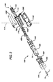
- Figure 2 is an exploded view of another lancing device, according to an exemplary embodiment described and illustrated herein.
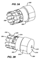
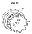
- Figures 3A-3C are perspective views of a lancet depth adjustment member and cap, according to an exemplary embodiment described and illustrated herein.
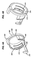
- FIGS. 4A-4B are perspective views of a lock ring, according to an exemplary embodiment described and illustrated herein.
- Figures 5A-5B are perspective views of a collar, according to an exemplary embodiment described and illustrated herein.
- Figures 6A-6B are perspective views of a movable member, according to an exemplary embodiment described and illustrated herein.
- Figures 6C-6D are perspective views of another movable member, according to an exemplary embodiment described and illustrated herein.
- Figures 7A-7B are perspective views of a floating magnet holder, according to an exemplary embodiment described and illustrated herein.
- Figures 8A-8B are perspective views of a second housing, according to an exemplary embodiment described and illustrated herein.
- Figures 8C-8D are perspective views of another second housing, according to an exemplary embodiment described and illustrated herein.
- Figures 9A-9B are perspective views of a first housing bottom half, according to an exemplary embodiment described and illustrated herein.
- Figures 10A-10B are perspective views of a first housing top half, according to an exemplary embodiment described and illustrated herein.
- FIGS 11A-11B are perspective views of a band, according to an exemplary embodiment described and illustrated herein.
- Figures 12A-12G illustrate a sequence of steps used in removing a lancet depth adjustment member and cap from a lancing device, according to an exemplary embodiment described and illustrated herein.
- Figures 13A-13D illustrate a sequence of steps used in capping and removing a lancet from a lancing device, according to an exemplary embodiment described and illustrated herein.
- Figures 14A-14E illustrate a sequence of steps used in loading a lancet into a lancing device, according to an exemplary embodiment described and illustrated herein.
- Figures 15A-15C illustrate a sequence of steps used in attaching a lancet depth adjustment member and cap to a lancing device and setting its depth of penetration, according to an exemplary embodiment described and illustrated herein.
- Figures 16A-16F illustrate a sequence of steps used in automatically firing a lancing device, according to an exemplary embodiment described and illustrated herein.
- Figure 16G illustrates an alternate main housing body.
- Figure 16H illustrates an alternate main housing body.
- Figures 17A-17B illustrate alternative first bias members in a lancing device, according to embodiments described and illustrated herein.
- Figures 18A-18C illustrate a lancing device returning to home position and being unlocked, according to an exemplary embodiment described and illustrated herein.
- FIG. 1 is an exploded view of lancing device 100, according to an exemplary embodiment described and illustrated herein.
- Lancing device 100 includes lancet depth adjustment member and cap 200, lock ring 300, collar 400, third bias member 102, movable member 600, first bias member 104, second housing 700, second bias member 106, first housing bottom 1100 (or alternately, a close-ended housing 1100'), first housing top 1200, and band 1300.
- Lancing device 100 includes lancing device proximal end 108 and lancing device distal end 110, and includes first housing top 1200 on the topside, and first housing bottom 1100 on the bottom side.
- second housing 700, first housing bottom 1100, first housing top 1200, and band 1300 are fixedly attached to each other, while lancet depth adjustment member and cap 200, lock ring 300, collar 400, third bias member 102, movable member 600, first bias member 104, and second bias member 106 are attached, but free to move.
- lancet depth adjustment member and cap 200, lock ring 300, collar 400, third bias member 102, movable member 600, second housing 700, second bias member 106, and band 1300 are assembled along an axis running from lancing device proximal end 108 to lancing device distal end 110, while first housing top 1200 and first housing bottom 1100 are assembled along an axis running perpendicular to an axis running from lancing device proximal end 108 to lancing device distal end 110.
- Lancet depth adjustment member and cap 200, lock ring 300, collar 400, third bias member 102, movable member 600, first bias member 104, second housing 700, second bias member 106, first housing bottom 1100, first housing top 1200, and band 1300 are generally snapped together, but can also be attached using adhesives or thermal bonding, such as, for example, ultrasonic welding.
- first housing top 1200, band 1300, and first housing bottom 1100 are attached using ultrasonic welding along their points of contact. Tight clearances are maintained between the components of lancing device 100, typically in the range of .001-.010".
- movable member 600 travels inside second housing 700 along an axis between lancing device proximal end 108 and lancing device distal end 110, with a clearance of approximately .004".
- lancet depth adjustment member and cap 200, lock ring 300, collar 400, third bias member 102, movable member 600, first bias member 104, second housing 700, second bias member 106, first housing bottom 1100, first housing top 1200, and band 1300 are operatively connected such that a target site (e.g., a user's skin target site) can be lanced with a lancet (e.g., lancet L that includes lancet needle N) held within lancing device 100.
- lancing device 100 is configured for launching lancet L such that lancet needle N lances a target site.
- lancet depth adjustment member and cap 200 is configured for a user to select (i.e., predetermine) needle penetration depth into a target site.
- Lancing device 100 can be any suitable size but can be beneficially sized to fit within the palm of a user's hand and has, therefore, a typical but non-limiting length in the range of 50 mm to 70 mm and a typical but non-limiting width in the range of about 10 mm to about 20 mm. Such a compact size is beneficial in that it requires less storage space and is less conspicuous than conventionally sized lancing devices.
- FIG. 2 is an exploded view of another lancing device 150, according to an exemplary embodiment described and illustrated herein.
- Lancing device 150 uses magnetic forces to move the lancing device.
- Lancing device 150 includes lancet depth adjustment member and cap 200, lock ring 300, collar 400, third bias member 102, movable member 650, first bias member (comprising floating magnet holder 1400, floating magnet floating magnet 114, and fixed magnet 116), second housing 750, second bias member 106, first housing bottom 1100, first housing top 1200, and band 1300.
- Lancing device 150 includes lancing device proximal end 108 and lancing device distal end 110, and includes first housing top 1200 on the topside, and first housing bottom 1100 on the bottom side.
- second housing 750, first housing bottom 1100, first housing top 1200, and band 1300 are fixedly attached to each other, while lancet depth adjustment member and cap 200, lock ring 300, collar 400, third bias member 102, movable member 650, first bias member (comprising floating magnet holder 1400, floating magnet floating magnet 114, and fixed magnet 116), and second bias member 106 are attached, but free to move.
- lancet depth adjustment member and cap 200, lock ring 300, collar 400, third bias member 102, movable member 650, second housing 750, second bias member 106, and band 1300 are assembled along an axis running from lancing device proximal end 108 to lancing device distal end 110, while first housing top 1200 and first housing bottom 1100 are assembled along an axis running perpendicular to an axis running from lancing device proximal end 108 to lancing device distal end 110.
- Lancet depth adjustment member and cap 200, lock ring 300, collar 400, third bias member 102, movable member 650, first bias member (comprising floating magnet holder 1400, floating magnet 114, and fixed magnet 116), second housing 750, second bias member 106, first housing bottom 1100, first housing top 1200, and band 1300 are generally snapped together, but can also be attached using adhesives or thermal bonding, such as, for example, ultrasonic welding.
- first housing top 1200, band 1300, and first housing bottom 1100 are attached using ultrasonic welding along their points of contact. Tight clearances are maintained between the components of lancing device 150, typically in the range of .001-.010" (0.025-0.25 mm).
- movable member 650 travels inside second housing 750 along an axis between lancing device proximal end 108 and lancing device distal end 110, with a clearance of approximately .004" (0.01 mm).
- lancet depth adjustment member and cap 200, lock ring 300, collar 400, third bias member 102, movable member 650, first bias member (comprising floating magnet holder 1400, floating magnet 114, and fixed magnet 116), second housing 750, second bias member 106, first housing bottom 1100, first housing top 1200, and band 1300 are operatively connected such that a target site (e.g., a user's skin target site) can be lanced with a lancet (e.g., lancet L that includes lancet needle N) held within lancing device 150.
- lancing device 150 is configured for launching lancet L such that lancet needle N lances a target site.
- lancet depth adjustment member and cap 200 is configured for a user to select (i.e., predetermine) needle penetration depth into a target site.
- Lancing device 150 can be any suitable size but can be beneficially sized to fit within the palm of a user's hand and has, therefore, a typical but non-limiting length in the range of 50 mm to 70 mm and a typical but non-limiting width in the range of about 10 mm to about 20 mm. Such a compact size is beneficial in that it requires less storage space and is less conspicuous than conventionally sized lancing devices.
- FIGS 3A-3C are perspective views of lancet depth adjustment member and cap 200, according to an exemplary embodiment described and illustrated herein.
- Lancet depth adjustment member and cap 200 includes outside wall 202, front wall 204, stop 206, inside wall 208, grips 210, opening 212, contour 214, depth indicators 216, locking fingers 218, catches 220, depth stops 222, and pockets 224.
- lancet depth adjustment member and cap 200 includes outside wall 202, which is attached to front wall 204.
- Front wall 204 includes opening 212, through which a lancet needle can travel, and contour 214, which can shape the target site.
- Depth indicators 216 are used in conjunction with depth stops 222 (illustrated in Figure 3C ), in setting the depth of penetration of a lancet needle.
- Stop 206 stops against features in lock ring 300, such as, for example, outside edge 314, when lancing device 100 or lancing device 150 is being primed.
- Locking fingers 218 are distributed around the perimeter of lancet depth adjustment member and cap 200, and alternate with pockets 224. When locked in place, catches 220 interact with features on lock ring 300, such as, for example, pegs 312, preventing lancet depth adjustment member and cap 200 from being removed. When unlocked, pockets 224 are in line with pegs 312, allowing lancet depth adjustment member and cap 200 to be removed from lancing device 100 or lancing device 150.
- Lancet depth adjustment member and cap 200 include grips 210, making it easier to rotate lancet depth adjustment member and cap 200. Inside wall 208 travels over the outside surface of collar 400, with minimal clearance, allowing for smooth and precise motion. Lancet depth adjustment member and cap 200 can be at least partially clear or opaque, and can be made using rigid or flexible materials. For example, lancet depth adjustment member and cap 200 can be injection molded using rigid thermoplastics, such as, for example, ABS, polycarbonate, acrylic, or polystyrene, or it can be injection or reaction injection molded using thermoplastic or thermosetting elastomers.
- rigid thermoplastics such as, for example, ABS, polycarbonate, acrylic, or polystyrene
- FIGs 4A-4B are perspective views of lock ring 300, according to an exemplary embodiment described and illustrated herein.
- Lock ring 300 includes grip 302, inside edge 304, guide 306, arm 308, catch 310, pegs 312, outside edge 314, inside surface 316, clasp 318, proximal end 324, and distal end 326.
- Grip 302 is used to rotate lock ring 300 about the axis that runs between lancing device proximal end 108 and lancing device distal end 110.
- Inside edge 304 rides against features first housing bottom 1100 and first housing top 1200, such as, for example, distal end 1106 and distal end 1204.
- Guide 306 positions lock ring 300 in features of first housing bottom 1100 and first housing top 1200, such as, for example, groove 1120 and groove 1218.
- Arm 308 and catch 310 extend from proximal end 324, and rotate into and out of contact with locking surface 638.
- catch 310 When catch 310 is in contact with locking surface 638 it prevents movable member 600 or movable member 650 from moving, and when catch 310 is not in contact with locking surface 638, movable member 600 or movable member 650 are free to move along the axis between lancing device proximal end 108 and lancing device distal end 110.
- Lancet depth adjustment member and cap 200 is locked in place when pegs 312 interact with catches 220, preventing lancet depth adjustment member and cap 200 and locking fingers 218 from sliding out of lancing device 100 or lancing device 150.
- Lancet depth adjustment member and cap 200 is unlocked, and can be removed from lancing device 100 or lancing device 150, by rotating lock ring 300 so that pegs 312 are aligned with pockets 224.
- Outside edge 314 provides a stop for stop 206, when lancet depth adjustment member and cap 200 travels towards lancing device proximal end 108, establishing the maximum travel of lancet depth adjustment member and cap 200 towards lancing device proximal end 108.
- Lock ring 300 can be at least partially clear or opaque, and can be made using rigid or flexible materials.
- lock ring 300 can be injection molded using rigid thermoplastics, such as, for example, ABS, polycarbonate, acrylic, or polystyrene, or it can be injection or reaction injection molded using thermoplastic or thermosetting elastomers.
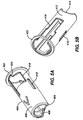
- FIGS 5A-5B are perspective views of collar 400, according to an exemplary embodiment described and illustrated herein.
- Collar 400 includes proximal end 402, distal end 404, bottom outside surface 406, inside surface 408, assembly windows 410, top outside surface 412, cutaway 414, top window 416, bottom window 418, catch window 420, and spring contact 422.
- proximal end 402 faces lancing device proximal end 108
- distal end 404 faces lancing device distal end 110.
- Top outside surface 412 includes cutaway 414, which allows access to a lancet in movable member 600 or movable member 650, as illustrated in Figures 13 and 14 .
- Top outside surface 412 also includes top window 416, which allows features such as, for example, priming arm 626, priming catch 629, and top landing 736 to clear top outside surface 412.
- Bottom outside surface 406 includes bottom window 418, which allows features such as, for example, catch 310 to clear bottom outside surface 406.
- Bottom window 418 includes catch window 420, which interacts with catch 310 to fix lock ring 300 in place when lancet depth adjustment member and cap 200 is removed. This is illustrated in Figures 12E-12F .
- Collar 400 includes inside surface 408, which rides along the outside surface of second housing 700 or second housing 750, when collar 400 travels along the axis between lancing device proximal end 108 and lancing device distal end 110.
- Collar 400 includes assembly windows 410, which interact with assembly pegs 732 during the assembly of lancing device 100 or lancing device 150, helping to position collar 400 relative to second housing 700 or second housing 750 during the assembly of lancing device 100 or lancing device 150.
- Spring contact 422 interacts with third bias member 102, biasing collar 400 in the direction of lancing device distal end 110, locking lock ring 300 in place by way of catch 310 and catch window 420 when lancet depth adjustment member and cap 200 is removed.
- Collar 400 can be at least partially clear or opaque, and can be made using rigid or flexible materials.
- collar 400 can be injection molded using rigid thermoplastics, such as, for example, ABS, polycarbonate, acrylic, or polystyrene, or it can be injection or reaction injection molded using thermoplastic or thermosetting elastomers.
- FIGS 6A-6B are perspective views of movable member 600, according to an exemplary embodiment described and illustrated herein.
- Movable member 600 includes distal end 602, proximal end 604, proximal bearings 606, distal bearings 608, launch spring housing 610, launch spring support 612, launch spring pin 613, stop tip 624, priming arm 626, priming catch 629, return arms 630, locking surface 638, lancet holder 640, expanding walls 642, ring 643, and ring groove 644.
- proximal end 604 faces lancing device proximal end 108
- distal end 602 faces lancing device distal end 110.
- Proximal bearings 606 and distal bearings 608 make contact with the inside of second housing 700 when movable member 600 travels toward lancing device proximal end 108 or lancing device distal end 110.
- the clearance between proximal bearings 606, distal bearings 608, and the inside of second housing 700 is small (on the order of .001 to .010"), providing smooth, tight motion, as opposed to sloppy, loose motion.
- First bias member 104 is mounted inside launch spring housing 610, centered on launch spring pin 613 and resting upon launch spring support 612.
- First bias member 104 is free to expand and contract, and provides a motive force for moving movable member 600 back and forth along the axis between lancing device proximal end 108 and lancing device distal end 110.
- Stop tip 624 is connected to distal end 602 and interacts with features in lancet depth adjustment member and cap 200, such as, for example, depth stops 222, to limit the travel of movable member 600 towards lancing device distal end 110.
- stop tip 624 is at least partially made with an acoustically dampened material, such as, for example, an elastomer, to minimize sound when firing lancing device 100.
- features on lancet depth adjustment member and cap 200 can also include acoustically dampened materials, such as, for example, an elastomer.
- Priming arm 626 and priming catch 629 are connected to movable member 600 and interact with features on lancet depth adjustment member and cap 200, such as, for example, locking fingers 218, when lancing device 100 is being primed and fired. Locking fingers 218 push priming catch 629 and movable member 600 toward lancing device proximal end 108 until priming catch 629 encounters firing ramp 1208.
- Firing ramp 1208 begins pushing priming catch 629 inward, away from locking fingers 218 until priming catch 629 clears locking fingers 218, allowing priming catch 629 and movable member 600 to rapidly travel towards lancing device distal end 110 during the firing cycle. While movable member 600 travels toward lancing device distal end 110 during the firing cycle, return arms 630 grip second bias member 106, compressing second bias member 106. Second bias member 106 provides the spring force to return movable member 600 to its home position after stop tip 624 has hit depth stops 222.
- Locking surface 638 interacts with catch 310 when lock ring 300 is rotated into its locked position, allowing lancet depth adjustment member and cap 200 to be removed and lancets to be loaded into lancet holder 640 while keeping movable member 600 fixed.
- Lancet holder 640 includes expanding walls 642, which expands when a lancet is inserted.
- Ring 643 (shown in Figure 14E ) sits in ring groove 644, limiting the extent to which expanding walls 642 can expand, and minimizing fatigue to expanding walls 642.
- Priming catch 629 and return arms 630 interact with features on second housing 700 to prevent rotation of movable member 600 about the axis running between lancing device proximal end 108 and lancing device distal end 110.
- Movable member 600 can be at least partially clear or opaque, and can be made using rigid materials.
- movable member 600 can be injection molded using rigid thermoplastics, including, but not limited to, ABS, acrylic, polycarbonate, polyester, polystyrene, polyamide, polyacetal, polyimide, polyketone, polyurethane, polybutyleneteraphthalate and combinations thereof.
- lubricants are added to the thermoplastic, to minimize friction between movable member 600 and other parts, such as, for example, second housing 700.
- lubricants can be added to the other parts, such as, for example, second housing 700, as long as the friction between movable member 600 and the other parts, such as, for example, second housing 700, remains small.
- Various lubricants can be used, such as, for example, fluoropolymers or silicones.
- FIGS 6C-6D are perspective views of movable member 650, according to an exemplary embodiment described and illustrated herein.
- Movable member 650 includes distal end 602, proximal end 604, proximal bearings 606, distal bearings 608, stop tip 624, priming arm 626, priming catch 629, return arms 630, magnet support 632, magnet holder guide 634, locking surface 638, lancet holder 640, expanding walls 642, ring 643, and ring groove 644.
- proximal end 604 faces lancing device proximal end 108
- distal end 602 faces lancing device distal end 110.
- Proximal bearings 606 and distal bearings 608 make contact with the inside of second housing 750 when movable member 600 travels toward lancing device proximal end 108 or lancing device distal end 110.
- the clearance between proximal bearings 606, distal bearings 608, and the inside of second housing 750 is small (on the order of .001 to .010") (0.025-0.25 mm), providing smooth, tight motion, as opposed to sloppy, loose motion.
- Floating magnet 114 is mounted into floating magnet holder 1400, while shaft 1406 rides in magnet holder guide 634 (as seen in Figure 17B ).
- Stop tip 624 is connected to distal end 602 and interacts with features in lancet depth adjustment member and cap 200, such as, for example, depth stops 222, to limit the travel of movable member 650 towards lancing device distal end 110.
- stop tip 624 is at least partially made with an acoustically dampened material, such as, for example, an elastomer, to minimize sound when firing lancing device 150.
- features on lancet depth adjustment member and cap 200 can also include acoustically dampened materials, such as, for example, an elastomer.
- Priming arm 626 and priming catch 629 are connected to movable member 650 and interact with features on lancet depth adjustment member and cap 200, such as, for example, locking fingers 218, when lancing device 150 is being primed and fired. Locking fingers 218 push priming catch 629 and movable member 650 toward lancing device proximal end 108 until priming catch 629 encounters firing ramp 1208.
- Firing ramp 1208 begins pushing priming catch 629 inward, away from locking fingers 218 until priming catch 629 clears locking fingers 218, allowing priming catch 629 and movable member 650 to rapidly travel towards lancing device distal end 110 during the firing cycle. While movable member 650 travels toward lancing device distal end 110 during the firing cycle, return arms 630 grip second bias member 106, compressing second bias member 106. Second bias member 106 provides the spring force to return movable member 650 to its home position after stop tip 624 has hit depth stops 222.
- Locking surface 638 interacts with catch 310 when lock ring 300 is rotated into its locked position, allowing lancet depth adjustment member and cap 200 to be removed and lancets to be loaded into lancet holder 640 while keeping movable member 650 fixed.
- Lancet holder 640 includes expanding walls 642, which expands when a lancet is inserted.
- Ring 643 (shown in Figure 14E ) sits in ring groove 644, limiting the extent to which expanding walls 642 can expand, and minimizing fatigue to expanding walls 642.
- Priming catch 629 and return arms 630 interact with features on second housing 750 to prevent rotation of movable member 650 about the axis running between lancing device proximal end 108 and lancing device distal end 110.
- Movable member 650 can be at least partially clear or opaque, and can be made using rigid materials.
- movable member 650 can be injection molded using rigid thermoplastics, including, but not limited to, ABS, acrylic, polycarbonate, polyester, polystyrene, polyamide, polyacetal, polyimide, polyketone, polyurethane, polybutyleneteraphthalate and combinations thereof.
- lubricants are added to the thermoplastic, to minimize friction between movable member 650 and other parts, such as, for example, second housing 750.
- lubricants can be added to the other parts, such as, for example, second housing 750, as long as the friction between movable member 650 and the other parts, such as, for example, second housing 750, remains small.
- Various lubricants can be used, such as, for example, fluoropolymers or silicones.
- FIGS 7A-7B are perspective views of floating magnet holder 1400, according to an exemplary embodiment described and illustrated herein.
- Floating magnet holder 1400 includes proximal end 1402, distal end 1404, shaft 1406, wall 1408, bottom 1410, ribs 1412, lower finger 1414, upper finger 1416, and contact surfaces 1418.
- proximal end 1402 distal end 1404, shaft 1406, wall 1408, bottom 1410, ribs 1412, lower finger 1414, upper finger 1416, and contact surfaces 1418.
- floating magnet 114 is pressed into proximal end 1402 until it seats against bottom 1410.
- Floating magnet 114 is retained in proximal end 1402 by ribs 1412.
- Shaft 1406 is inserted into magnet holder guide 634, and is free to travel towards distal end 602 and proximal end 604.
- Floating magnet holder 1400 When floating magnet holder 1400 travels toward lancing device distal end 110, contact surfaces 1418 makes contact with magnet support 632, driving 65 forward. Eventually lower finger 1414 and upper finger 1416 hit second housing 750 limiting the travel of floating magnet holder 1400. At that point, movable member 650 loses contact with floating magnet holder 1400 and travels toward lancing device distal end 110 due to its forward momentum.
- Floating magnet holder 1400 can be at least partially clear or opaque, and can be made using rigid materials.
- floating magnet holder 1400 can be injection molded using rigid thermoplastics, including, but not limited to, ABS, acrylic, polycarbonate, polyester, polystyrene, polyamide, polyacetal, polyimide, polyketone, polyurethane, polybutyleneteraphthalate and combinations thereof.
- lubricants are added to the thermoplastic, to minimize friction between floating magnet holder 1400 and other parts, such as, for example, movable member 650.
- lubricants can be added to the other parts, such as, for example, movable member 650, as long as the friction between floating magnet holder 1400 and the other parts, such as, for example, movable member 650, remains small.
- Various lubricants can be used, such as, for example, fluoropolymers or silicones.
- FIGs 8A-8B are perspective views of second housing 700, according to an exemplary embodiment described and illustrated herein.
- Second housing 700 includes distal end 702, top 703, proximal end 704, 705, inner surface 706, priming window 714, return windows 716, stop window 718, mandrels 722, positioning grooves 724, lock window 730, assembly pegs 732, and top landing 736.
- proximal end 704 faces lancing device proximal end 108
- distal end 702 faces lancing device distal end 110.
- Figure 8A illustrates features on top 703, while Figure 8B illustrates features on 705.
- Second housing 700 includes inner surface 706 which extends from proximal end 704 to distal end 702 and provides smooth contact surfaces for mating parts, such as, for example, proximal bearings 606 and distal bearings 608.
- Priming window 714, return windows 716, stop window 718, and lock window 730 provide access between the inside and outside of second housing 700, and in some cases provide contact surfaces that register other parts to second housing 700.
- Positioning grooves 724 interact with features in first housing bottom 1100 and first housing top 1200, such as, for example, positioning ribs 1110 and positioning ribs 1206.
- Mandrels 722 provides inside support for third bias member 102 and second bias member 106, while return windows 716 allow return arms 630 to grip second bias member 106.
- Priming window 714 provides clearance for priming catch 629
- return windows 716 provides clearance for return arms 630
- stop window 718 provides clearance for stop tip 624
- lock window 730 provides clearance for catch 310.
- Top landing 736 mates with features on collar 400, such as, for example, top window 416, and prevents collar 400 from rotating about the axis between lancing device proximal end 108 and 110.
- Assembly pegs 732 are used in the assembly of lancing device 100, and serve no purpose after assembly.
- Second housing 700 can be at least partially clear or opaque, and can be made using rigid materials.
- second housing 700 can be injection molded using rigid thermoplastics, including, but not limited to, ABS, acrylic, polycarbonate, polyester, polystyrene, polyamide, polyacetal, polyimide, polyketone, polyurethane, polybutyleneteraphthalate and combinations thereof.
- lubricants are added to the thermoplastic, to minimize friction between second housing 700 and other parts, such as, for example, movable member 600.
- lubricants can be added to the other parts, such as, for example, movable member 600, as long as the friction between second housing 700 and the other parts, such as, for example, movable member 600, remains small.
- Various lubricants can be used, such as, for example, fluoropolymers or silicones.
- FIGs 8C-8D are perspective views of second housing 750, according to an exemplary embodiment described and illustrated herein.
- Second housing 750 includes distal end 702, top 703, proximal end 704, 705, inner surface 706, priming window 714, return windows 716, stop window 718, mandrels 722, positioning grooves 724, lock window 730, assembly pegs 732, and top landing 736.
- proximal end 704 faces lancing device proximal end 108
- distal end 702 faces 110.
- Figure 8D illustrates features on top 703, while Figure 8C illustrates features on 705.
- Second housing 750 includes inner surface 706 which extends from proximal end 704 to distal end 702 and provides smooth contact surfaces for mating parts, such as, for example, proximal bearings 606 and distal bearings 608. Priming window 714, return windows 716, stop window 718, lock window 730, and magnet holder windows 734 provide access between the inside and outside of second housing 750, and in some cases provide contact surfaces that register other parts to second housing 750. Positioning grooves 724 interact with features in first housing bottom 1100 and first housing top 1200, such as positioning ribs 1110 and positioning ribs 1206.
- Mandrels 722 provides inside support for third bias member 102 and second bias member 106, while return windows 716 allow return arms 630 to grip second bias member 106.
- Priming window 714 provides clearance for priming catch 629
- return windows 716 provides clearance for return arms 630
- stop window 718 provides clearance for stop tip 624
- lock window 730 provides clearance for catch 310
- magnet holder windows 734 provide clearance for lower finger 1414 and upper finger 1416.
- Top landing 736 mates with features on collar 400, such as, for example, top window 416, and prevents collar 400 from rotating about the axis between lancing device proximal end 108 and lancing device distal end 110.
- Assembly pegs 732 are used in the assembly of lancing device 150, and serve no purpose after assembly.
- Second housing 750 can be at least partially clear or opaque, and can be made using rigid materials.
- second housing 750 can be injection molded using rigid thermoplastics, including, but not limited to, ABS, acrylic, polycarbonate, polyester, polystyrene, polyamide, polyacetal, polyimide, polyketone, polyurethane, polybutyleneteraphthalate and combinations thereof.
- lubricants are added to the thermoplastic, to minimize friction between second housing 750 and other parts, such as movable member 650.
- lubricants can be added to the other parts, such as movable member 650, as long as the friction between second housing 750 and the other parts, such as movable member 650, remains small.
- Various lubricants can be used, such as, for example, fluoropolymers or silicones.
- Figures 9A-9B are perspective views of first housing bottom 1100, according to an exemplary embodiment described and illustrated herein.
- First housing bottom 1100 includes grip 1102, distal end 1106, proximal end 1108, positioning ribs 1110, outside surface 1112, inside surface 1114, fastening ribs 1116, clasp pocket 1118, and groove 1120.
- proximal end 1108 is placed at lancing device proximal end 108, while distal end 1106 is placed facing lancing device distal end 110.
- Outside surface 1112 includes grip 1102, which allows for enhanced handling of lancing device 100 or lancing device 150, and in the embodiment illustrated in Figure 11 is made by molding a recess in outside surface 1112.
- First housing bottom 1100 also includes fastening ribs 1116, which can be used in fastening first housing bottom 1100 to first housing top 1200 and/or band 1300, using methods such as, for example, ultrasonic welding.
- Groove 1120 mates with features on lock ring 300, such as guide 306, precisely positioning lock ring 300 and allowing rotation of lock ring 300 about the axis between lancing device proximal end 108 and lancing device distal end 110.
- Clasp pocket 1118 interacts with features on lock ring 300, such as clasp 318, tensioning clasp 318 against clasp pocket 1118 and providing a smooth fit between lock ring 300 and first housing bottom 1100.
- First housing bottom 1100 can be at least partially clear or opaque, and can be made using rigid materials.
- first housing bottom 1100 can be injection molded using rigid thermoplastics, including, but not limited to, ABS, acrylic, polycarbonate, polyester, polystyrene, polyamide, polyacetal, polyimide, polyketone, polyurethane, polybutyleneteraphthalate and combinations thereof.
- First housing bottom 1100 can also be formed of semi-rigid materials including, for example, polypropylene, high-density polyethylene, polyurethane, ethylene propylene rubber, polymethylpentene and combinations thereof.
- Figures 10A-10B are perspective views of first housing top 1200, according to an exemplary embodiment described and illustrated herein.
- First housing top 1200 includes proximal end 1202, distal end 1204, depth window 1205, positioning ribs 1206, firing ramp 1208, grip 1210, outside surface 1212, inside surface 1214, fastening ribs 1216, groove 1218.
- proximal end 1202 is placed at lancing device proximal end 108, while distal end 1204 is placed facing lancing device distal end 110.
- Outside surface 1212 includes grip 1210, which allows for enhanced handling of lancing device 100 or lancing device 150, and in the embodiment illustrated in Figure 12 is made by molding a recess in outside surface 1212.
- First housing top 1200 also includes fastening ribs 1216, which can be used in fastening first housing top 1200 to first housing bottom 1100 and/or band 1300, using methods such as, for example, ultrasonic welding.
- Groove 1218 mates with features on lock ring 300, such as guide 306, precisely positioning lock ring 300 and allowing rotation of lock ring 300 about the axis between lancing device proximal end 108 and lancing device distal end 110.
- Firing ramp 1208 interacts with features on movable member 600 or movable member 650, such as priming catch 629, pushing priming catch 629 away from locking fingers 218 at the instant lancing device 100 or lancing device 150 is fired.
- Depth window 1205 allows depth indicators 216 to be viewed, when lancet depth adjustment member and cap 200 sets the depth of lancet penetration.
- First housing top 1200 can be at least partially clear or opaque, and can be made using rigid materials.
- first housing top 1200 can be injection molded using rigid thermoplastics, including, but not limited to, ABS, acrylic, polycarbonate, polyester, polystyrene, polyamide, polyacetal, polyimide, polyketone, polyurethane, polybutyleneteraphthalate and combinations thereof.
- First housing top 1200 can also be formed of semi-rigid materials including, for example, polypropylene, high-density polyethylene, polyurethane, ethylene propylene rubber, polymethylpentene and combinations thereof.
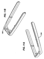
- FIGS 11A-11B are perspective views of band 1300, according to an exemplary embodiment described and illustrated herein.
- Eyelet 1302 provides a fastening point for key rings or other optional accessories.
- Band 1300 can be at least partially clear or opaque, and can be made using rigid materials.
- band 1300 can be injection molded using rigid thermoplastics, including, but not limited to, ABS, acrylic, polycarbonate, polyester, polystyrene, polyamide, polyacetal, polyimide, polyketone, polyurethane, polybutyleneteraphthalate and combinations thereof.
- Band 1300 can also be formed of semi-rigid materials including, for example, polypropylene, high-density polyethylene, polyurethane, ethylene propylene rubber, polymethylpentene and combinations thereof.
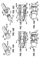
- Figures 12A-12G illustrate a sequence of steps used in removing a lancet depth adjustment member and cap from lancing device 100 or lancing device 150, according to an exemplary embodiment described and illustrated herein.
- lancing device 100 or lancing device 150 is in the home position. Lancet depth adjustment member and cap 200 is locked in place, since grip 302 is in the locked position.
- grip 302 is rotated, in the direction of arrow A1, into an unlocked position. In this position, lancet depth adjustment member and cap 200 can be removed from lancing device 100 or lancing device 150, as indicated by arrow A2 in Figure 12C .
- FIG. 12D is a cross sectional view of lancing device distal end 110 at the stage illustrated in Figure 12A .
- catches 220 are in contact with pegs 312, preventing lancet depth adjustment member and cap 200 from being removed from lancing device distal end 110.
- Figure 12E is a cross sectional view of lancing device distal end 110 at the stage illustrated in Figure 12B .
- FIG 12E grip 302 has been rotated into an unlocked position, and lancet depth adjustment member and cap 200 can be removed by pulling it out of lancing device distal end 110 in the direction of arrow A3.
- catch 310 rotates into proximity with locking surface 638, preventing movable member 600 or movable member 650 from moving towards lancing device proximal end 108 when replacing lancet L1.
- pegs 312 rotate away from catches 220, allowing lancet depth adjustment member and cap 200 to be moved away from lancing device distal end 110.
- Figure 12F is a partial assembly view of lancing device distal end 110 at the stage illustrated in Figure 12A .
- FIG 12F grip 302 is still in the locked position, and catch 310 has not engaged with catch window 420.
- Third bias member 102 pushes collar 400 toward lancing device distal end 110, but catch 310 is free to rotate.
- Figure 12G is a partial assembly view of lancing device distal end 110 at the stage illustrated in Figure 12C .
- grip 302 has been moved into an unlocked position, lancet depth adjustment member and cap 200 has been removed from lancing device distal end 110, and catch 310 engages catch window 420.
- Third bias member 102 pushes collar 400 in the direction indicated by arrow A4, and catch 310 prevents lock ring 300 from being rotated when lancet depth adjustment member and cap 200 has been removed from lancing device distal end 110.
- Figures 13A-13D illustrate a sequence of steps used in capping and removing a lancet from lancing device 100 or lancing device 150, according to an exemplary embodiment described and illustrated herein.
- lancing device 100 or lancing device 150 is in the stage illustrated in Figure 12C .
- Lancet L1 is inside collar 400, and needs to be replaced.
- New lancet L2 with cap C2 are moved in the direction indicated by arrow A5.
- lancet L2 and cap C2 continue to move in the direction of arrow A6, while collar 400 begins to move in the direction indicated by arrow A7.
- Lancet L2 is positioned in cutaway 414, while cap C2 seats on lancet L1.
- FIG 13C the assembly of lancet L1, cap C2, and lancet L2 is removed from lancing device 100 or lancing device 150, and collar 400 springs back in the direction indicated by arrow A8.
- Figure 13D is a cross sectional view of lancing device distal end 110 at the stage illustrated in Figure 13B .
- cap C2 has been moved in the direction indicated by arrow A6 and is attached to used lancet L1.
- Catch 310 catches against locking surface 638, preventing movable member 600 or movable member 650 from moving toward lancing device proximal end 108.
- Collar 400 moves in the direction indicated by arrow A7 as cap C2 seats on lancet L1, but is limited in motion.
- Figures 14A-14E illustrate a sequence of steps used in loading a lancet into lancing device 100 or lancing device 150, according to an exemplary embodiment described and illustrated herein.
- the lancet assembly from Figure 13C is rotated so that new lancet L2 faces lancing device 100 or lancing device 150.
- Lancet L2 is moved towards lancing device 100 or lancing device 150, as indicated by arrow A9.
- lancet L2 is inserted into collar 400 and lancet holder 640 (as illustrated in Figure 14E ), as indicated by arrow A10.
- collar 400 moves back, as indicated by arrow A11.
- lancet L1 is rotated as indicated by arrow A13 in Figure 14C .
- Rotating lancet L1 breaks cap C2 free from lancet L2, allowing lancet L1 and cap C2 to be removed from lancet L2.
- collar 400 pushes further back, away from lancet L1 and cap C2, as indicated by arrow A12.
- cap C2 breaks free from lancet L2
- the assembly of cap C2 and lancet L1 can be removed, and disposed of, as indicated by arrow A14 in Figure 14D .
- collar 400 springs back, in the direction indicated by arrow A15, and lancet L2 is ready for use.
- FIG 14E is a partial assembly view of lancing device distal end 110 at the stage illustrated in Figure 14A , before insertion of lancet L2.
- movable member 600 or movable member 650 include lancet holder 640 and expanding walls 642.
- Expanding walls 642 includes ring 643 in ring groove 644. Ring 643 prevents fatigue in expanding walls 642 when lancets are inserted and removed from lancet holder 640.
- Figures 15A-15C illustrate a sequence of steps used in attaching a lancet depth adjustment member and cap to lancing device 100 or lancing device 150 and setting their depth of penetration, according to an exemplary embodiment described and illustrated herein.
- lancing device 100 or lancing device 150 has been loaded with new lancet L2, as illustrated in Figurel4D.
- Lancet depth adjustment member and cap 200 is moved into lancing device distal end 110, in the direction indicated by arrow A16.
- Figure 15B lancet depth adjustment member and cap 200 has been completely inserted into lancing device distal end 110, and grip 302 is moved into the locked position, as indicated by arrow A17.
- the depth is set by rotating lancet depth adjustment member and cap 200, in the direction indicated by arrow A18, and observing depth indicators 216 in depth window 1205.
- depth indicators 216 correlate to specific depth stops 222, and establish the position at which stop tip 624 hits depth stops 222.
- the position at which stop tip 624 hits depth stops 222 establishes the travel of movable member 600 or 605, and therefore the depth of penetration of needle N into the target site.
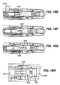
- FIGs 16A-16D illustrate a sequence of steps used in automatically firing lancing device 100 or lancing device 150, according to an exemplary embodiment described and illustrated herein.
- lancet depth adjustment member and cap 200 makes contact with a target site (not shown for clarity) and is pushed in, as indicated by arrow A19.
- Stop 206 ( Fig. 16D ) moves toward outside edge 314, while grip 302 is in its locked position and depth indicators 216 indicate the depth of penetration.
- lancet depth adjustment member and cap 200 has made initial contact with a target site, and is pushed in the direction indicated by arrow A20.
- Locking fingers 218 pushes on priming catch 629, moving movable member 600 or movable member 650 in the direction indicated by arrow A21.
- Priming catch 629 makes initial contact with firing ramp 1208, but has not yet been pushed inward and is still caught on the edge of locking fingers 218.
- first bias member 104 compresses, building force used during the firing step.
- priming catch 629 has been pushed in enough to clear locking fingers 218 and first bias member 104 pushes movable member 600 or movable member 650 in the direction indicated by arrow A22. At maximum travel in Fig.
- stop tip 624 strikes depth stops 222, while needle N travels through opening 212 and into the target site. While movable member 600 or movable member 650 travels in the direction indicated by arrow A22, first bias member 104 expands, and return arms 630 grab and expand second bias member 106. Once stop tip 624 hits depth stops 222, second bias member 106 pulls movable member 600 or movable member 650 back towards the home position, as indicated by arrow A23 in Figure 16D . In Figure 16D , needle N has moved back through opening 212, first bias member 104 and second bias member 106 have moved to a balanced position, and stop tip 624 is no longer in contact with depth stops 222.
- Figures 16E-16G illustrate a similar sequence of priming and contemporaneously and automatically firing of the lancet N using a non-contact bias in the exemplary form of a magnet 116.
- the operation of the embodiment shown in Figures 16E-16G is essentially identical to the operation in the embodiment shown in Figures 16A-16D .
- Figures 17A-17B illustrate alternative first bias members in lancing device 100 or lancing device 150, according to embodiments described and illustrated herein.
- first bias member 104 is a spring, and provides the force necessary for lancing. First bias member 104 is compressed when movable member 600 moves toward lancing device proximal end 108, and expands when movable member 600 moves toward lancing device distal end 110.
- the first bias member includes floating magnet 114, fixed magnet 116, and floating magnet holder 1400.
- Floating magnet 114 and fixed magnet 116 are mounted with either their north or south poles facing each other, so as movable member 650, floating magnet holder 1400, and floating magnet 114 approach fixed magnet 116 during priming of lancing device 150, magnetic repulsion force is generated.
- movable member 650, floating magnet holder 1400, and floating magnet 114 move away from fixed magnet 116, eventually reaching their maximum penetration depth.
- floating magnet holder 1400 disengages from movable member 650, and movable member 650 travels toward lancing device distal end 110 using its forward momentum.
- Any type of permanent magnet can be used for floating magnet 114 and fixed magnet 116, such as, for example, neodymium-iron-boron (NIB) and other rare earth magnets.
- NNB neodymium-iron-boron
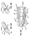
- Figures 18A-18C illustrate lancing device 100 or lancing device 150 returning to home position and being unlocked, according to an exemplary embodiment described and illustrated herein.
- an automatic prime and firing sequence has just been completed, as illustrated in Figure 16D .
- lancet depth adjustment member and cap 200 moves in the direction indicated by arrow A24.
- Figure 18C is a cross sectional view of lancing device distal end 110 at the stage illustrated in Figure 18A .
- stop 206 has moved away from outside edge 314, locking fingers 218 have moved away from priming catch 629, and needle N has moved away from opening 212.
- lancing device 100 or lancing device 150 is in its home position. Grip 302 can be moved into an unlocked position, as indicated by arrow A25, preventing movable member 600 or movable member 650 from moving, and disabling the automatic prime and fire sequence. Although lancet depth adjustment member and cap 200 can be removed in this position, lancing device 100 or lancing device 150 cannot be accidentally primed or fired when grip 302 is in the unlocked position, illustrated in Figure 18B .
Landscapes
- Health & Medical Sciences (AREA)
- Life Sciences & Earth Sciences (AREA)
- Heart & Thoracic Surgery (AREA)
- Medical Informatics (AREA)
- Biophysics (AREA)
- Pathology (AREA)
- Engineering & Computer Science (AREA)
- Biomedical Technology (AREA)
- Hematology (AREA)
- Physics & Mathematics (AREA)
- Molecular Biology (AREA)
- Surgery (AREA)
- Animal Behavior & Ethology (AREA)
- General Health & Medical Sciences (AREA)
- Public Health (AREA)
- Veterinary Medicine (AREA)
- Dermatology (AREA)
- Measurement Of The Respiration, Hearing Ability, Form, And Blood Characteristics Of Living Organisms (AREA)
Claims (12)
- Lanzettenvorrichtung (100; 150), umfassend:ein Gehäuse (1100, 1200), das beabstandete proximale und distale Enden aufweist, die entlang einer Längsachse angeordnet sind;ein bewegbares Element (600; 650), das in dem Gehäuse angeordnet ist und für eine Bewegung entlang der Längsachse konfiguriert ist;einen Kragen (400), der teilweise in dem Gehäuse angeordnet ist;eine Lanzette (L);einen drehbaren Ring (300); undein Lanzettentiefeneinstellelement (200), das sowohl durch den drehbaren Ring als auch den Kragen so festgehalten wird, dass das Lanzettentiefeneinstellelement bezüglich des Gehäuses drehbar ist, um eine Vielzahl von Anschlagflächen für das bewegbare Element bereitzustellen, während sich das bewegbare Element entlang der Längsachse zum Distalende bewegt;
dadurch gekennzeichnet, dass das Tiefeneinstellelement (200) während des Entsicherns der Vorrichtung (100; 150) so auf den Kragen (400) und das bewegbare Element (600, 650) einwirkt, dass sich der Kragen, das bewegbare Element und die Lanzette als eine Einheit bewegen. - Lanzettenvorrichtung nach Anspruch 1, ferner umfassend:ein in dem Gehäuse angeordnetes zweites Gehäuse (700; 750), wobei das zweite Gehäuse das bewegbare Element teilweise umgibt, um eine Führung der Bewegung des bewegbaren Elements bereitzustellen; undein erstes Vorspannelement (104; 1400, 114, 116), das sich in dem zweiten Gehäuse befindet, um das bewegbare Element in Richtung auf das Distalende vorzuspannen;
- Lanzettenvorrichtung nach Anspruch 2, wobei das bewegbare Element eine Vielzahl von Armen (630) umfasst, die sich von der Längsachse ab in Richtung auf das Distalende erstrecken, wobei einer der Vielzahl von Armen konfiguriert ist, einen Vorsprung in Eingriff zu bringen, der auf einer internen Oberfläche des Gehäuses gebildet ist, um das bewegbare Element gegen das erste Vorspannelement in einer entsicherten Position festzuhalten.
- Lanzettenvorrichtung nach einem vorstehenden Anspruch, wobei das Gehäuse zwei Hälften umfasst, die miteinander verbunden sind.
- Lanzettenvorrichtung nach Anspruch 3 oder 4, wobei das Gehäuse ein erstes Gehäuse (1100, 1200) und ein zweites Gehäuse (700, 750) umfasst, das zweite Gehäuse in dem ersten Gehäuse in einem feststehenden Verhältnis zu dem ersten Gehäuse angeordnet ist, und wobei das zweite Gehäuse ein unitäres Element umfasst, das mit einem Positionierungsband (1300) verbunden ist, das mit dem ersten Gehäuse gekoppelt ist, wobei das zweite Gehäuse mindestens eine Längsrille (716) aufweist, die sich durch das unitäre Element entlang der Längsachse erstreckt, um eine Kommunikation vom Innern des zweiten Gehäuses bis zum Innern des ersten Gehäuses zu ermöglichen.
- Lanzettenvorrichtung nach Anspruch 3, 4 oder 5, ferner umfassend ein zweites Vorspannelement (106), das konfiguriert ist, das bewegbare Element in einer Richtung zum Proximalende vorzuspannen.
- Lanzettenvorrichtung nach Anspruch 6, wobei das bewegbare Element mindestens einen Rückstellarm (630) aufweist, der sich durch die Längsrille erstreckt, so dass das bewegbare Element durch den mindestens einen Rückstellarm auf einem Weg geführt wird, der von der Längsrille definiert wird.
- Lanzettenvorrichtung nach Anspruch 7, wobei das zweite Vorspannelement eine Schraubenfeder umfasst, die außerhalb des zweiten Gehäuses angeordnet ist und mit dem mindestens einen Rückstellarm verbunden ist.
- Lanzettenvorrichtung nach einem der Ansprüche 6 bis 8, ferner umfassend ein drittes Vorspannelement (102), das in dem Gehäuse angeordnet ist, um gegen den Kragen in Distalrichtung entlang der Längsachse vorzuspannen.
- Lanzettenvorrichtung nach einem vorstehenden Anspruch, wobei das Tiefeneinstellelement mindestens einen Feststellfinger (218) umfasst, der sich allgemein entlang der Längsachse erstreckt.
- Lanzettenvorrichtung nach Anspruch 1, wobei das bewegbare Element mindestens einen Betätigungsarm umfasst, der sich allgemein entlang der Längsachse erstreckt und konfiguriert ist, einen Vorsprung in Eingriff zu bringen, der auf einer internen Oberfläche des Gehäuses gebildet ist, um das bewegbare Element gegen ein erstes Vorspannelement (104; 1400, 114, 116) in einer entsicherten Position festzuhalten.
- Lanzettenvorrichtung nach Anspruch 2 oder 11, wobei das erste Vorspannelement aus einer Gruppe ausgewählt wird, die aus Federn, Magneten oder Kombinationen davon besteht.
Applications Claiming Priority (2)
| Application Number | Priority Date | Filing Date | Title |
|---|---|---|---|
| US5208808P | 2008-05-09 | 2008-05-09 | |
| EP09742368A EP2320799B1 (de) | 2008-05-09 | 2009-05-07 | Lanzettenvorrichtungen und verfahren |
Related Parent Applications (1)
| Application Number | Title | Priority Date | Filing Date |
|---|---|---|---|
| EP09742368A Division EP2320799B1 (de) | 2008-05-09 | 2009-05-07 | Lanzettenvorrichtungen und verfahren |
Publications (2)
| Publication Number | Publication Date |
|---|---|
| EP2497422A1 EP2497422A1 (de) | 2012-09-12 |
| EP2497422B1 true EP2497422B1 (de) | 2014-11-05 |
Family
ID=40874680
Family Applications (2)
| Application Number | Title | Priority Date | Filing Date |
|---|---|---|---|
| EP12167994.8A Not-in-force EP2497422B1 (de) | 2008-05-09 | 2009-05-07 | Stechhilfevorrichtungen und -verfahren |
| EP09742368A Not-in-force EP2320799B1 (de) | 2008-05-09 | 2009-05-07 | Lanzettenvorrichtungen und verfahren |
Family Applications After (1)
| Application Number | Title | Priority Date | Filing Date |
|---|---|---|---|
| EP09742368A Not-in-force EP2320799B1 (de) | 2008-05-09 | 2009-05-07 | Lanzettenvorrichtungen und verfahren |
Country Status (8)
| Country | Link |
|---|---|
| US (1) | US8454533B2 (de) |
| EP (2) | EP2497422B1 (de) |
| JP (1) | JP5567554B2 (de) |
| CN (1) | CN102014748B (de) |
| CA (1) | CA2723549C (de) |
| ES (2) | ES2401728T3 (de) |
| TW (1) | TWI508705B (de) |
| WO (1) | WO2009136172A2 (de) |
Families Citing this family (59)
| Publication number | Priority date | Publication date | Assignee | Title |
|---|---|---|---|---|
| US6391005B1 (en) | 1998-03-30 | 2002-05-21 | Agilent Technologies, Inc. | Apparatus and method for penetration with shaft having a sensor for sensing penetration depth |
| US8641644B2 (en) | 2000-11-21 | 2014-02-04 | Sanofi-Aventis Deutschland Gmbh | Blood testing apparatus having a rotatable cartridge with multiple lancing elements and testing means |
| US9427532B2 (en) | 2001-06-12 | 2016-08-30 | Sanofi-Aventis Deutschland Gmbh | Tissue penetration device |
| US7981056B2 (en) | 2002-04-19 | 2011-07-19 | Pelikan Technologies, Inc. | Methods and apparatus for lancet actuation |
| US9795747B2 (en) | 2010-06-02 | 2017-10-24 | Sanofi-Aventis Deutschland Gmbh | Methods and apparatus for lancet actuation |
| US7344507B2 (en) | 2002-04-19 | 2008-03-18 | Pelikan Technologies, Inc. | Method and apparatus for lancet actuation |
| US9226699B2 (en) | 2002-04-19 | 2016-01-05 | Sanofi-Aventis Deutschland Gmbh | Body fluid sampling module with a continuous compression tissue interface surface |
| AU2002348683A1 (en) | 2001-06-12 | 2002-12-23 | Pelikan Technologies, Inc. | Method and apparatus for lancet launching device integrated onto a blood-sampling cartridge |
| US7041068B2 (en) | 2001-06-12 | 2006-05-09 | Pelikan Technologies, Inc. | Sampling module device and method |
| WO2002100460A2 (en) | 2001-06-12 | 2002-12-19 | Pelikan Technologies, Inc. | Electric lancet actuator |
| US8337419B2 (en) | 2002-04-19 | 2012-12-25 | Sanofi-Aventis Deutschland Gmbh | Tissue penetration device |
| CA2448902C (en) | 2001-06-12 | 2010-09-07 | Pelikan Technologies, Inc. | Self optimizing lancing device with adaptation means to temporal variations in cutaneous properties |
| US7226461B2 (en) | 2002-04-19 | 2007-06-05 | Pelikan Technologies, Inc. | Method and apparatus for a multi-use body fluid sampling device with sterility barrier release |
| US8784335B2 (en) | 2002-04-19 | 2014-07-22 | Sanofi-Aventis Deutschland Gmbh | Body fluid sampling device with a capacitive sensor |
| US7892185B2 (en) | 2002-04-19 | 2011-02-22 | Pelikan Technologies, Inc. | Method and apparatus for body fluid sampling and analyte sensing |
| US7297122B2 (en) | 2002-04-19 | 2007-11-20 | Pelikan Technologies, Inc. | Method and apparatus for penetrating tissue |
| US7909778B2 (en) | 2002-04-19 | 2011-03-22 | Pelikan Technologies, Inc. | Method and apparatus for penetrating tissue |
| US7976476B2 (en) | 2002-04-19 | 2011-07-12 | Pelikan Technologies, Inc. | Device and method for variable speed lancet |
| US9248267B2 (en) | 2002-04-19 | 2016-02-02 | Sanofi-Aventis Deustchland Gmbh | Tissue penetration device |
| US8702624B2 (en) | 2006-09-29 | 2014-04-22 | Sanofi-Aventis Deutschland Gmbh | Analyte measurement device with a single shot actuator |
| US9795334B2 (en) | 2002-04-19 | 2017-10-24 | Sanofi-Aventis Deutschland Gmbh | Method and apparatus for penetrating tissue |
| US8221334B2 (en) | 2002-04-19 | 2012-07-17 | Sanofi-Aventis Deutschland Gmbh | Method and apparatus for penetrating tissue |
| US7892183B2 (en) | 2002-04-19 | 2011-02-22 | Pelikan Technologies, Inc. | Method and apparatus for body fluid sampling and analyte sensing |
| US9314194B2 (en) | 2002-04-19 | 2016-04-19 | Sanofi-Aventis Deutschland Gmbh | Tissue penetration device |
| US7232451B2 (en) | 2002-04-19 | 2007-06-19 | Pelikan Technologies, Inc. | Method and apparatus for penetrating tissue |
| US7331931B2 (en) | 2002-04-19 | 2008-02-19 | Pelikan Technologies, Inc. | Method and apparatus for penetrating tissue |
| US7901362B2 (en) | 2002-04-19 | 2011-03-08 | Pelikan Technologies, Inc. | Method and apparatus for penetrating tissue |
| US8579831B2 (en) | 2002-04-19 | 2013-11-12 | Sanofi-Aventis Deutschland Gmbh | Method and apparatus for penetrating tissue |
| US7547287B2 (en) | 2002-04-19 | 2009-06-16 | Pelikan Technologies, Inc. | Method and apparatus for penetrating tissue |
| US7491178B2 (en) | 2002-04-19 | 2009-02-17 | Pelikan Technologies, Inc. | Method and apparatus for penetrating tissue |
| US8267870B2 (en) | 2002-04-19 | 2012-09-18 | Sanofi-Aventis Deutschland Gmbh | Method and apparatus for body fluid sampling with hybrid actuation |
| US7229458B2 (en) | 2002-04-19 | 2007-06-12 | Pelikan Technologies, Inc. | Method and apparatus for penetrating tissue |
| US8360992B2 (en) | 2002-04-19 | 2013-01-29 | Sanofi-Aventis Deutschland Gmbh | Method and apparatus for penetrating tissue |
| US7674232B2 (en) | 2002-04-19 | 2010-03-09 | Pelikan Technologies, Inc. | Method and apparatus for penetrating tissue |
| US8574895B2 (en) | 2002-12-30 | 2013-11-05 | Sanofi-Aventis Deutschland Gmbh | Method and apparatus using optical techniques to measure analyte levels |
| EP2238892A3 (de) | 2003-05-30 | 2011-02-09 | Pelikan Technologies Inc. | Vorrichtung zur Entnahme von Körperflüssigkeit |
| ES2490740T3 (es) | 2003-06-06 | 2014-09-04 | Sanofi-Aventis Deutschland Gmbh | Aparato para toma de muestras de fluido sanguíneo y detección de analitos |
| WO2006001797A1 (en) | 2004-06-14 | 2006-01-05 | Pelikan Technologies, Inc. | Low pain penetrating |
| EP1671096A4 (de) | 2003-09-29 | 2009-09-16 | Pelikan Technologies Inc | Verfahren und apparatur für eine verbesserte probeneinfangvorrichtung |
| EP1680014A4 (de) | 2003-10-14 | 2009-01-21 | Pelikan Technologies Inc | Verfahren und gerät für eine variable anwenderschnittstelle |
| US7822454B1 (en) | 2005-01-03 | 2010-10-26 | Pelikan Technologies, Inc. | Fluid sampling device with improved analyte detecting member configuration |
| WO2005065414A2 (en) | 2003-12-31 | 2005-07-21 | Pelikan Technologies, Inc. | Method and apparatus for improving fluidic flow and sample capture |
| US8828203B2 (en) | 2004-05-20 | 2014-09-09 | Sanofi-Aventis Deutschland Gmbh | Printable hydrogels for biosensors |
| US9775553B2 (en) | 2004-06-03 | 2017-10-03 | Sanofi-Aventis Deutschland Gmbh | Method and apparatus for a fluid sampling device |
| EP1765194A4 (de) | 2004-06-03 | 2010-09-29 | Pelikan Technologies Inc | Verfahren und gerät für eine flüssigkeitsentnahmenvorrichtung |
| US8652831B2 (en) | 2004-12-30 | 2014-02-18 | Sanofi-Aventis Deutschland Gmbh | Method and apparatus for analyte measurement test time |
| EP2265324B1 (de) | 2008-04-11 | 2015-01-28 | Sanofi-Aventis Deutschland GmbH | Integriertes System zur Messung von Analyten |
| US8932314B2 (en) * | 2008-05-09 | 2015-01-13 | Lifescan Scotland Limited | Prime and fire lancing device with contacting bias drive and method |
| US9375169B2 (en) | 2009-01-30 | 2016-06-28 | Sanofi-Aventis Deutschland Gmbh | Cam drive for managing disposable penetrating member actions with a single motor and motor and control system |
| US8460211B2 (en) * | 2010-01-19 | 2013-06-11 | Christopher A. Jacobs | Vacuum assisted lancing system with bidirectional mechanism and method for blood extraction with minimal pain |
| US8965476B2 (en) | 2010-04-16 | 2015-02-24 | Sanofi-Aventis Deutschland Gmbh | Tissue penetration device |
| GB2489740A (en) | 2011-04-08 | 2012-10-10 | Owen Mumford Ltd | Means for securely retaining a lancet in a lancing device |
| CN102579057B (zh) * | 2011-11-09 | 2013-10-09 | 苏州施莱医疗器械有限公司 | 安全型采血笔 |
| CN102379705B (zh) * | 2011-11-09 | 2013-01-09 | 苏州施莱医疗器械有限公司 | 一种安全采血笔 |
| TWI477256B (zh) * | 2012-01-19 | 2015-03-21 | Bionime Corp | 穿刺裝置 |
| DE102012107749B3 (de) * | 2012-08-22 | 2013-12-12 | Gerresheimer Regensburg Gmbh | Stechhilfe zur Gewinnung von Körperflüssigkeitsproben |
| US20140088632A1 (en) * | 2012-09-21 | 2014-03-27 | Stat Medical Devices, Inc. | Lancet device utilizing a magnet and method of making and using the same |
| WO2014202431A1 (en) | 2013-06-19 | 2014-12-24 | Borealis Ag | Polypropylene with broad molecular weight distribution |
| USD787680S1 (en) * | 2015-06-18 | 2017-05-23 | Maureen Donohue | Glucose monitor and lancet combination |
Family Cites Families (59)
| Publication number | Priority date | Publication date | Assignee | Title |
|---|---|---|---|---|
| US83222A (en) * | 1868-10-20 | John blake tarr | ||
| US100656A (en) * | 1870-03-08 | Improvement in card-racks | ||
| US125019A (en) * | 1872-03-26 | Improvement in wood pavements | ||
| US267229A (en) * | 1882-11-07 | William l | ||
| US173876A (en) * | 1876-02-22 | Improvement in wind-wheels | ||
| US39885A (en) * | 1863-09-15 | Improvement in presses | ||
| US247671A (en) * | 1881-09-27 | Jar-holder | ||
| US173875A (en) * | 1876-02-22 | Improvement in cooking-stoves | ||
| US55297A (en) * | 1866-06-05 | Improvement in cider-mills | ||
| US255300A (en) * | 1882-03-21 | Automatic hydraulic press | ||
| US125017A (en) * | 1872-03-26 | Improvement in preparing fertilizing materials from earth | ||
| US234492A (en) * | 1880-11-16 | Stencil | ||
| US187470A (en) * | 1877-02-20 | Improvement in cultivators | ||
| US52809A (en) * | 1866-02-27 | Improvement in harvesters | ||
| FR2508305B1 (fr) * | 1981-06-25 | 1986-04-11 | Slama Gerard | Dispositif pour provoquer une petite piqure en vue de recueillir une goutte de sang |
| US4462405A (en) * | 1982-09-27 | 1984-07-31 | Ehrlich Joseph C | Blood letting apparatus |
| US4986724A (en) * | 1987-11-10 | 1991-01-22 | Cincinnati Milacron Inc. | System for compensated motion of coupled robot axes |
| US4895147A (en) * | 1988-10-28 | 1990-01-23 | Sherwood Medical Company | Lancet injector |
| US4976724A (en) | 1989-08-25 | 1990-12-11 | Lifescan, Inc. | Lancet ejector mechanism |
| US5207699A (en) * | 1989-10-30 | 1993-05-04 | Coe Frederick L | Lancet handling and disposal assembly |
| JPH0595937A (ja) | 1991-07-09 | 1993-04-20 | Meitec Corp | 採血器 |
| CA2079192C (en) * | 1992-09-25 | 1995-12-26 | Bernard Strong | Combined lancet and multi-function cap and lancet injector for use therewith |
| US5350392A (en) * | 1994-02-03 | 1994-09-27 | Miles Inc. | Lancing device with automatic cocking |
| US5628764A (en) * | 1995-03-21 | 1997-05-13 | Schraga; Steven | Collar lancet device |
| WO1997043962A1 (en) * | 1996-05-17 | 1997-11-27 | Mercury Diagnostics, Inc. | Methods and apparatus for expressing body fluid from an incision |
| US5868772A (en) * | 1997-07-31 | 1999-02-09 | Bayer Corporation | Blood sampling device with anti-twist lancet holder |
| US5964718A (en) * | 1997-11-21 | 1999-10-12 | Mercury Diagnostics, Inc. | Body fluid sampling device |
| US6197040B1 (en) * | 1999-02-23 | 2001-03-06 | Lifescan, Inc. | Lancing device having a releasable connector |
| US6558402B1 (en) | 1999-08-03 | 2003-05-06 | Becton, Dickinson And Company | Lancer |
| GB9928876D0 (en) * | 1999-12-08 | 2000-02-02 | Owen Mumford Ltd | Improvements relating to combined lancets and caps |
| PL191428B1 (pl) * | 2000-04-06 | 2006-05-31 | Htl Strefa Sp Z Oo | Zespół regulacji głębokości nakłucia w przyrządzie do nakłuwania |
| EP1358844B1 (de) * | 2001-01-12 | 2010-09-01 | ARKRAY, Inc. | Punktiervorrichtung |
| US7041068B2 (en) * | 2001-06-12 | 2006-05-09 | Pelikan Technologies, Inc. | Sampling module device and method |
| IL155681A0 (en) | 2001-08-16 | 2003-11-23 | Inverness Medical Ltd | In-situ adapter for a testing device |
| US6645219B2 (en) * | 2001-09-07 | 2003-11-11 | Amira Medical | Rotatable penetration depth adjusting arrangement |
| ATE556645T1 (de) * | 2001-12-07 | 2012-05-15 | Micronix Inc | Konsolidierte körperflüssigkeits-testvorrichtung und verfahren |
| US6589261B1 (en) * | 2002-08-19 | 2003-07-08 | Vitalcare Group, Inc. | Lancet needle anchor and method |
| US6852119B1 (en) * | 2002-09-09 | 2005-02-08 | Ramzi F. Abulhaj | Adjustable disposable lancet and method |
| JP4296035B2 (ja) | 2003-05-21 | 2009-07-15 | アークレイ株式会社 | 穿刺装置 |
| GB0320283D0 (en) * | 2003-08-29 | 2003-10-01 | Owen Mumford Ltd | Improvements relating to lancets |
| JP2005124998A (ja) * | 2003-10-27 | 2005-05-19 | Sekisui Chem Co Ltd | 穿刺具 |
| US20050125019A1 (en) | 2003-12-05 | 2005-06-09 | Paul Kudrna | Lancet device and method |
| US20050125017A1 (en) | 2003-12-05 | 2005-06-09 | Paul Kudrna | Lancet device and method |
| WO2005077275A1 (en) | 2004-02-06 | 2005-08-25 | Bayer Healthcare Llc | Dampening and retraction mechanism for a lancing device |
| JP2005253781A (ja) | 2004-03-12 | 2005-09-22 | Misawa Ika Kogyo Kk | 穿刺具用キャップ |
| WO2005089333A2 (en) | 2004-03-15 | 2005-09-29 | Oakville Hong Kong Company Limited | Lancet device and method of use |
| JP2005312763A (ja) * | 2004-04-30 | 2005-11-10 | Arkray Inc | 穿刺針カートリッジ、穿刺器具、先端ユニットおよびアダプタ |
| US9380975B2 (en) | 2004-05-07 | 2016-07-05 | Becton, Dickinson And Company | Contact activated lancet device |
| US20070255300A1 (en) | 2004-08-19 | 2007-11-01 | Facet Technologies, Llc | Loosely coupled lancet |
| US20060100655A1 (en) | 2004-10-28 | 2006-05-11 | Koon-Wah Leong | Combined lancing and auxiliary device |
| US20060100656A1 (en) | 2004-10-28 | 2006-05-11 | Olson Lorin P | Compact lancing device |
| US8672962B2 (en) | 2005-04-28 | 2014-03-18 | Bayer Healthcare Llc | Permanent magnet lancing device |
| US20060247671A1 (en) | 2005-05-02 | 2006-11-02 | Levaughn Richard W | Compact, multi-use micro-sampling device |
| KR100716015B1 (ko) | 2005-06-08 | 2007-05-08 | 유재천 | 란셋 장치 및 이를 이용한 혈액의 채취 및 주입 방법 |
| US20070083222A1 (en) | 2005-06-16 | 2007-04-12 | Stat Medical Devices, Inc. | Lancet device, removal system for lancet device, and method |
| EP1901655B1 (de) | 2005-07-13 | 2018-12-19 | Roche Diabetes Care GmbH | Lanzettenvorrichtung |
| US20070173876A1 (en) | 2006-01-20 | 2007-07-26 | Lifescan, Inc. | Lancing device with dampened spring |
| WO2007130830A2 (en) | 2006-04-25 | 2007-11-15 | Facet Technologies, Llc | Lancing device with independent drive core |
| CN200945164Y (zh) * | 2006-08-14 | 2007-09-12 | 施国平 | 一次性可调穿刺深度安全采血针 |
-
2009
- 2009-05-05 US US12/435,991 patent/US8454533B2/en not_active Expired - Fee Related
- 2009-05-07 ES ES09742368T patent/ES2401728T3/es active Active
- 2009-05-07 WO PCT/GB2009/001157 patent/WO2009136172A2/en not_active Ceased
- 2009-05-07 CN CN200980117628.7A patent/CN102014748B/zh not_active Expired - Fee Related
- 2009-05-07 EP EP12167994.8A patent/EP2497422B1/de not_active Not-in-force
- 2009-05-07 ES ES12167994.8T patent/ES2529136T3/es active Active
- 2009-05-07 JP JP2011507989A patent/JP5567554B2/ja not_active Expired - Fee Related
- 2009-05-07 CA CA2723549A patent/CA2723549C/en not_active Expired - Fee Related
- 2009-05-07 EP EP09742368A patent/EP2320799B1/de not_active Not-in-force
- 2009-05-08 TW TW098115219A patent/TWI508705B/zh not_active IP Right Cessation
Also Published As
| Publication number | Publication date |
|---|---|
| EP2320799A2 (de) | 2011-05-18 |
| WO2009136172A2 (en) | 2009-11-12 |
| JP5567554B2 (ja) | 2014-08-06 |
| HK1174240A1 (en) | 2013-06-07 |
| JP2011519649A (ja) | 2011-07-14 |
| ES2401728T3 (es) | 2013-04-24 |
| TWI508705B (zh) | 2015-11-21 |
| EP2320799B1 (de) | 2013-02-20 |
| EP2497422A1 (de) | 2012-09-12 |
| US20090281459A1 (en) | 2009-11-12 |
| HK1156832A1 (en) | 2012-06-22 |
| ES2529136T3 (es) | 2015-02-17 |
| CN102014748B (zh) | 2014-06-25 |
| CN102014748A (zh) | 2011-04-13 |
| CA2723549C (en) | 2016-11-29 |
| TW201008552A (en) | 2010-03-01 |
| CA2723549A1 (en) | 2009-11-12 |
| WO2009136172A3 (en) | 2010-01-07 |
| US8454533B2 (en) | 2013-06-04 |
Similar Documents
| Publication | Publication Date | Title |
|---|---|---|
| EP2320799B1 (de) | Lanzettenvorrichtungen und verfahren | |
| EP2320800B1 (de) | Priming- und auslöse-lanzettenvorrichtung mit kontaktvorrspannantrieb und verfahren | |
| US20090281457A1 (en) | Prime and fire lancing device with non-contacting bias drive and method | |
| US20080194989A1 (en) | Methods and apparatus for lancet actuation | |
| HK1174240B (en) | Lancing devices and methods | |
| HK1156832B (en) | Lancing devices and methods | |
| CN101232847B (zh) | 穿刺器具 | |
| HK1156830B (en) | Prime and fire lancing device with contact bias drive and method | |
| HK1183785B (en) | Prime and fire lancing device with contact bias drive |
Legal Events
| Date | Code | Title | Description |
|---|---|---|---|
| PUAI | Public reference made under article 153(3) epc to a published international application that has entered the european phase |
Free format text: ORIGINAL CODE: 0009012 |
|
| AC | Divisional application: reference to earlier application |
Ref document number: 2320799 Country of ref document: EP Kind code of ref document: P |
|
| AK | Designated contracting states |
Kind code of ref document: A1 Designated state(s): AT BE BG CH CY CZ DE DK EE ES FI FR GB GR HR HU IE IS IT LI LT LU LV MC MK MT NL NO PL PT RO SE SI SK TR |
|
| 17P | Request for examination filed |
Effective date: 20130312 |
|
| REG | Reference to a national code |
Ref country code: HK Ref legal event code: DE Ref document number: 1174240 Country of ref document: HK |
|
| 17Q | First examination report despatched |
Effective date: 20130819 |
|
| GRAP | Despatch of communication of intention to grant a patent |
Free format text: ORIGINAL CODE: EPIDOSNIGR1 |
|
| INTG | Intention to grant announced |
Effective date: 20140422 |
|
| GRAP | Despatch of communication of intention to grant a patent |
Free format text: ORIGINAL CODE: EPIDOSNIGR1 |
|
| INTG | Intention to grant announced |
Effective date: 20140703 |
|
| GRAS | Grant fee paid |
Free format text: ORIGINAL CODE: EPIDOSNIGR3 |
|
| GRAA | (expected) grant |
Free format text: ORIGINAL CODE: 0009210 |
|
| AC | Divisional application: reference to earlier application |
Ref document number: 2320799 Country of ref document: EP Kind code of ref document: P |
|
| AK | Designated contracting states |
Kind code of ref document: B1 Designated state(s): AT BE BG CH CY CZ DE DK EE ES FI FR GB GR HR HU IE IS IT LI LT LU LV MC MK MT NL NO PL PT RO SE SI SK TR |
|
| REG | Reference to a national code |
Ref country code: GB Ref legal event code: FG4D |
|
| REG | Reference to a national code |
Ref country code: CH Ref legal event code: NV Representative=s name: E. BLUM AND CO. AG PATENT- UND MARKENANWAELTE , CH Ref country code: CH Ref legal event code: EP |
|
| REG | Reference to a national code |
Ref country code: AT Ref legal event code: REF Ref document number: 694152 Country of ref document: AT Kind code of ref document: T Effective date: 20141115 |
|
| REG | Reference to a national code |
Ref country code: IE Ref legal event code: FG4D |
|
| REG | Reference to a national code |
Ref country code: DE Ref legal event code: R096 Ref document number: 602009027654 Country of ref document: DE Effective date: 20141224 |
|
| REG | Reference to a national code |
Ref country code: ES Ref legal event code: FG2A Ref document number: 2529136 Country of ref document: ES Kind code of ref document: T3 Effective date: 20150217 |
|
| REG | Reference to a national code |
Ref country code: AT Ref legal event code: MK05 Ref document number: 694152 Country of ref document: AT Kind code of ref document: T Effective date: 20141105 |
|
| REG | Reference to a national code |
Ref country code: NL Ref legal event code: VDEP Effective date: 20141105 |
|
| REG | Reference to a national code |
Ref country code: LT Ref legal event code: MG4D |
|
| PG25 | Lapsed in a contracting state [announced via postgrant information from national office to epo] |
Ref country code: FI Free format text: LAPSE BECAUSE OF FAILURE TO SUBMIT A TRANSLATION OF THE DESCRIPTION OR TO PAY THE FEE WITHIN THE PRESCRIBED TIME-LIMIT Effective date: 20141105 Ref country code: IS Free format text: LAPSE BECAUSE OF FAILURE TO SUBMIT A TRANSLATION OF THE DESCRIPTION OR TO PAY THE FEE WITHIN THE PRESCRIBED TIME-LIMIT Effective date: 20150305 Ref country code: NL Free format text: LAPSE BECAUSE OF FAILURE TO SUBMIT A TRANSLATION OF THE DESCRIPTION OR TO PAY THE FEE WITHIN THE PRESCRIBED TIME-LIMIT Effective date: 20141105 Ref country code: PT Free format text: LAPSE BECAUSE OF FAILURE TO SUBMIT A TRANSLATION OF THE DESCRIPTION OR TO PAY THE FEE WITHIN THE PRESCRIBED TIME-LIMIT Effective date: 20150305 Ref country code: NO Free format text: LAPSE BECAUSE OF FAILURE TO SUBMIT A TRANSLATION OF THE DESCRIPTION OR TO PAY THE FEE WITHIN THE PRESCRIBED TIME-LIMIT Effective date: 20150205 Ref country code: LT Free format text: LAPSE BECAUSE OF FAILURE TO SUBMIT A TRANSLATION OF THE DESCRIPTION OR TO PAY THE FEE WITHIN THE PRESCRIBED TIME-LIMIT Effective date: 20141105 |
|
| PG25 | Lapsed in a contracting state [announced via postgrant information from national office to epo] |
Ref country code: GR Free format text: LAPSE BECAUSE OF FAILURE TO SUBMIT A TRANSLATION OF THE DESCRIPTION OR TO PAY THE FEE WITHIN THE PRESCRIBED TIME-LIMIT Effective date: 20150206 Ref country code: CY Free format text: LAPSE BECAUSE OF FAILURE TO SUBMIT A TRANSLATION OF THE DESCRIPTION OR TO PAY THE FEE WITHIN THE PRESCRIBED TIME-LIMIT Effective date: 20141105 Ref country code: PL Free format text: LAPSE BECAUSE OF FAILURE TO SUBMIT A TRANSLATION OF THE DESCRIPTION OR TO PAY THE FEE WITHIN THE PRESCRIBED TIME-LIMIT Effective date: 20141105 Ref country code: HR Free format text: LAPSE BECAUSE OF FAILURE TO SUBMIT A TRANSLATION OF THE DESCRIPTION OR TO PAY THE FEE WITHIN THE PRESCRIBED TIME-LIMIT Effective date: 20141105 Ref country code: SE Free format text: LAPSE BECAUSE OF FAILURE TO SUBMIT A TRANSLATION OF THE DESCRIPTION OR TO PAY THE FEE WITHIN THE PRESCRIBED TIME-LIMIT Effective date: 20141105 Ref country code: AT Free format text: LAPSE BECAUSE OF FAILURE TO SUBMIT A TRANSLATION OF THE DESCRIPTION OR TO PAY THE FEE WITHIN THE PRESCRIBED TIME-LIMIT Effective date: 20141105 Ref country code: LV Free format text: LAPSE BECAUSE OF FAILURE TO SUBMIT A TRANSLATION OF THE DESCRIPTION OR TO PAY THE FEE WITHIN THE PRESCRIBED TIME-LIMIT Effective date: 20141105 |
|
| PG25 | Lapsed in a contracting state [announced via postgrant information from national office to epo] |
Ref country code: CZ Free format text: LAPSE BECAUSE OF FAILURE TO SUBMIT A TRANSLATION OF THE DESCRIPTION OR TO PAY THE FEE WITHIN THE PRESCRIBED TIME-LIMIT Effective date: 20141105 Ref country code: DK Free format text: LAPSE BECAUSE OF FAILURE TO SUBMIT A TRANSLATION OF THE DESCRIPTION OR TO PAY THE FEE WITHIN THE PRESCRIBED TIME-LIMIT Effective date: 20141105 Ref country code: EE Free format text: LAPSE BECAUSE OF FAILURE TO SUBMIT A TRANSLATION OF THE DESCRIPTION OR TO PAY THE FEE WITHIN THE PRESCRIBED TIME-LIMIT Effective date: 20141105 Ref country code: SK Free format text: LAPSE BECAUSE OF FAILURE TO SUBMIT A TRANSLATION OF THE DESCRIPTION OR TO PAY THE FEE WITHIN THE PRESCRIBED TIME-LIMIT Effective date: 20141105 |
|
| REG | Reference to a national code |
Ref country code: DE Ref legal event code: R097 Ref document number: 602009027654 Country of ref document: DE |
|
| PLBE | No opposition filed within time limit |
Free format text: ORIGINAL CODE: 0009261 |
|
| STAA | Information on the status of an ep patent application or granted ep patent |
Free format text: STATUS: NO OPPOSITION FILED WITHIN TIME LIMIT |
|
| REG | Reference to a national code |
Ref country code: HK Ref legal event code: GR Ref document number: 1174240 Country of ref document: HK |
|
| 26N | No opposition filed |
Effective date: 20150806 |
|
| PG25 | Lapsed in a contracting state [announced via postgrant information from national office to epo] |
Ref country code: LU Free format text: LAPSE BECAUSE OF FAILURE TO SUBMIT A TRANSLATION OF THE DESCRIPTION OR TO PAY THE FEE WITHIN THE PRESCRIBED TIME-LIMIT Effective date: 20150507 Ref country code: MC Free format text: LAPSE BECAUSE OF FAILURE TO SUBMIT A TRANSLATION OF THE DESCRIPTION OR TO PAY THE FEE WITHIN THE PRESCRIBED TIME-LIMIT Effective date: 20141105 |
|
| PG25 | Lapsed in a contracting state [announced via postgrant information from national office to epo] |
Ref country code: SI Free format text: LAPSE BECAUSE OF FAILURE TO SUBMIT A TRANSLATION OF THE DESCRIPTION OR TO PAY THE FEE WITHIN THE PRESCRIBED TIME-LIMIT Effective date: 20141105 |
|
| REG | Reference to a national code |
Ref country code: FR Ref legal event code: PLFP Year of fee payment: 8 |
|
| PG25 | Lapsed in a contracting state [announced via postgrant information from national office to epo] |
Ref country code: RO Free format text: LAPSE BECAUSE OF FAILURE TO SUBMIT A TRANSLATION OF THE DESCRIPTION OR TO PAY THE FEE WITHIN THE PRESCRIBED TIME-LIMIT Effective date: 20141105 |
|
| PG25 | Lapsed in a contracting state [announced via postgrant information from national office to epo] |
Ref country code: MT Free format text: LAPSE BECAUSE OF FAILURE TO SUBMIT A TRANSLATION OF THE DESCRIPTION OR TO PAY THE FEE WITHIN THE PRESCRIBED TIME-LIMIT Effective date: 20141105 |
|
| REG | Reference to a national code |
Ref country code: FR Ref legal event code: PLFP Year of fee payment: 9 |
|
| PG25 | Lapsed in a contracting state [announced via postgrant information from national office to epo] |
Ref country code: BG Free format text: LAPSE BECAUSE OF FAILURE TO SUBMIT A TRANSLATION OF THE DESCRIPTION OR TO PAY THE FEE WITHIN THE PRESCRIBED TIME-LIMIT Effective date: 20141105 Ref country code: HU Free format text: LAPSE BECAUSE OF FAILURE TO SUBMIT A TRANSLATION OF THE DESCRIPTION OR TO PAY THE FEE WITHIN THE PRESCRIBED TIME-LIMIT; INVALID AB INITIO Effective date: 20090507 |
|
| PG25 | Lapsed in a contracting state [announced via postgrant information from national office to epo] |
Ref country code: TR Free format text: LAPSE BECAUSE OF FAILURE TO SUBMIT A TRANSLATION OF THE DESCRIPTION OR TO PAY THE FEE WITHIN THE PRESCRIBED TIME-LIMIT Effective date: 20141105 |
|
| PG25 | Lapsed in a contracting state [announced via postgrant information from national office to epo] |
Ref country code: BE Free format text: LAPSE BECAUSE OF FAILURE TO SUBMIT A TRANSLATION OF THE DESCRIPTION OR TO PAY THE FEE WITHIN THE PRESCRIBED TIME-LIMIT Effective date: 20141105 |
|
| REG | Reference to a national code |
Ref country code: FR Ref legal event code: PLFP Year of fee payment: 10 |
|
| PGFP | Annual fee paid to national office [announced via postgrant information from national office to epo] |
Ref country code: GB Payment date: 20180329 Year of fee payment: 10 |
|
| PG25 | Lapsed in a contracting state [announced via postgrant information from national office to epo] |
Ref country code: MK Free format text: LAPSE BECAUSE OF FAILURE TO SUBMIT A TRANSLATION OF THE DESCRIPTION OR TO PAY THE FEE WITHIN THE PRESCRIBED TIME-LIMIT Effective date: 20141105 |
|
| PGFP | Annual fee paid to national office [announced via postgrant information from national office to epo] |
Ref country code: IE Payment date: 20180509 Year of fee payment: 10 Ref country code: DE Payment date: 20180424 Year of fee payment: 10 Ref country code: CH Payment date: 20180516 Year of fee payment: 10 Ref country code: ES Payment date: 20180601 Year of fee payment: 10 |
|
| PGFP | Annual fee paid to national office [announced via postgrant information from national office to epo] |
Ref country code: IT Payment date: 20180522 Year of fee payment: 10 Ref country code: FR Payment date: 20180411 Year of fee payment: 10 |
|
| REG | Reference to a national code |
Ref country code: DE Ref legal event code: R119 Ref document number: 602009027654 Country of ref document: DE |
|
| REG | Reference to a national code |
Ref country code: CH Ref legal event code: PL |
|
| GBPC | Gb: european patent ceased through non-payment of renewal fee |
Effective date: 20190507 |
|
| PG25 | Lapsed in a contracting state [announced via postgrant information from national office to epo] |
Ref country code: LI Free format text: LAPSE BECAUSE OF NON-PAYMENT OF DUE FEES Effective date: 20190531 Ref country code: CH Free format text: LAPSE BECAUSE OF NON-PAYMENT OF DUE FEES Effective date: 20190531 |
|
| PG25 | Lapsed in a contracting state [announced via postgrant information from national office to epo] |
Ref country code: GB Free format text: LAPSE BECAUSE OF NON-PAYMENT OF DUE FEES Effective date: 20190507 Ref country code: IE Free format text: LAPSE BECAUSE OF NON-PAYMENT OF DUE FEES Effective date: 20190507 Ref country code: DE Free format text: LAPSE BECAUSE OF NON-PAYMENT OF DUE FEES Effective date: 20191203 Ref country code: IT Free format text: LAPSE BECAUSE OF NON-PAYMENT OF DUE FEES Effective date: 20190507 |
|
| PG25 | Lapsed in a contracting state [announced via postgrant information from national office to epo] |
Ref country code: FR Free format text: LAPSE BECAUSE OF NON-PAYMENT OF DUE FEES Effective date: 20190531 |
|
| REG | Reference to a national code |
Ref country code: ES Ref legal event code: FD2A Effective date: 20200925 |
|
| PG25 | Lapsed in a contracting state [announced via postgrant information from national office to epo] |
Ref country code: ES Free format text: LAPSE BECAUSE OF NON-PAYMENT OF DUE FEES Effective date: 20190508 |