EP2495617B1 - Bilderzeugungsvorrichtung und Verfahren für die Farbregistrierungsberichtigung - Google Patents
Bilderzeugungsvorrichtung und Verfahren für die Farbregistrierungsberichtigung Download PDFInfo
- Publication number
- EP2495617B1 EP2495617B1 EP11185459.2A EP11185459A EP2495617B1 EP 2495617 B1 EP2495617 B1 EP 2495617B1 EP 11185459 A EP11185459 A EP 11185459A EP 2495617 B1 EP2495617 B1 EP 2495617B1
- Authority
- EP
- European Patent Office
- Prior art keywords
- light
- amount
- image forming
- registration sensor
- registration
- Prior art date
- Legal status (The legal status is an assumption and is not a legal conclusion. Google has not performed a legal analysis and makes no representation as to the accuracy of the status listed.)
- Not-in-force
Links
Images






Classifications
-
- G—PHYSICS
- G03—PHOTOGRAPHY; CINEMATOGRAPHY; ANALOGOUS TECHNIQUES USING WAVES OTHER THAN OPTICAL WAVES; ELECTROGRAPHY; HOLOGRAPHY
- G03G—ELECTROGRAPHY; ELECTROPHOTOGRAPHY; MAGNETOGRAPHY
- G03G15/00—Apparatus for electrographic processes using a charge pattern
- G03G15/50—Machine control of apparatus for electrographic processes using a charge pattern, e.g. regulating differents parts of the machine, multimode copiers, microprocessor control
- G03G15/5054—Machine control of apparatus for electrographic processes using a charge pattern, e.g. regulating differents parts of the machine, multimode copiers, microprocessor control by measuring the characteristics of an intermediate image carrying member or the characteristics of an image on an intermediate image carrying member, e.g. intermediate transfer belt or drum, conveyor belt
- G03G15/5058—Machine control of apparatus for electrographic processes using a charge pattern, e.g. regulating differents parts of the machine, multimode copiers, microprocessor control by measuring the characteristics of an intermediate image carrying member or the characteristics of an image on an intermediate image carrying member, e.g. intermediate transfer belt or drum, conveyor belt using a test patch
-
- G—PHYSICS
- G03—PHOTOGRAPHY; CINEMATOGRAPHY; ANALOGOUS TECHNIQUES USING WAVES OTHER THAN OPTICAL WAVES; ELECTROGRAPHY; HOLOGRAPHY
- G03G—ELECTROGRAPHY; ELECTROPHOTOGRAPHY; MAGNETOGRAPHY
- G03G15/00—Apparatus for electrographic processes using a charge pattern
- G03G15/01—Apparatus for electrographic processes using a charge pattern for producing multicoloured copies
- G03G15/0105—Details of unit
- G03G15/0131—Details of unit for transferring a pattern to a second base
-
- G—PHYSICS
- G03—PHOTOGRAPHY; CINEMATOGRAPHY; ANALOGOUS TECHNIQUES USING WAVES OTHER THAN OPTICAL WAVES; ELECTROGRAPHY; HOLOGRAPHY
- G03G—ELECTROGRAPHY; ELECTROPHOTOGRAPHY; MAGNETOGRAPHY
- G03G2215/00—Apparatus for electrophotographic processes
- G03G2215/01—Apparatus for electrophotographic processes for producing multicoloured copies
- G03G2215/0103—Plural electrographic recording members
- G03G2215/0119—Linear arrangement adjacent plural transfer points
-
- G—PHYSICS
- G03—PHOTOGRAPHY; CINEMATOGRAPHY; ANALOGOUS TECHNIQUES USING WAVES OTHER THAN OPTICAL WAVES; ELECTROGRAPHY; HOLOGRAPHY
- G03G—ELECTROGRAPHY; ELECTROPHOTOGRAPHY; MAGNETOGRAPHY
- G03G2215/00—Apparatus for electrophotographic processes
- G03G2215/01—Apparatus for electrophotographic processes for producing multicoloured copies
- G03G2215/0103—Plural electrographic recording members
- G03G2215/0119—Linear arrangement adjacent plural transfer points
- G03G2215/0122—Linear arrangement adjacent plural transfer points primary transfer to an intermediate transfer belt
- G03G2215/0125—Linear arrangement adjacent plural transfer points primary transfer to an intermediate transfer belt the linear arrangement being horizontal or slanted
-
- G—PHYSICS
- G03—PHOTOGRAPHY; CINEMATOGRAPHY; ANALOGOUS TECHNIQUES USING WAVES OTHER THAN OPTICAL WAVES; ELECTROGRAPHY; HOLOGRAPHY
- G03G—ELECTROGRAPHY; ELECTROPHOTOGRAPHY; MAGNETOGRAPHY
- G03G2215/00—Apparatus for electrophotographic processes
- G03G2215/01—Apparatus for electrophotographic processes for producing multicoloured copies
- G03G2215/0151—Apparatus for electrophotographic processes for producing multicoloured copies characterised by the technical problem
- G03G2215/0158—Colour registration
- G03G2215/0161—Generation of registration marks
Definitions
- aspects relate to an image forming apparatus and a method for color registration correction, and more particularly, to an image forming apparatus which can swiftly adjust an amount of light of a registration sensor, which examines an image alignment of the image forming apparatus, in a feedback manner, and a method for color registration correction.
- An electrophotographic printer such as a color laser printer includes four organic photo conductors Dy, Dc, Dm, and Dk prepared to respond to four colors, yellow, cyan, magenta, and black, a laser scanning unit to scan each of the organic photo conductors Dy, Dc, Dm, and Dk with a laser to form an electrostatic latent image of a desired image, a developing apparatus to develop the electrostatic latent image with color developers, and a transfer belt (or an intermediate transfer belt) to receive images developed on the organic photo conductors Dy, Dc, Dm, and Dk in sequence such that the images overlap with one another to form a complete color image, and transfer the color image to paper.
- the printer develops images for respective colors on the four organic photo conductors Dy, Dc, Dm, and Dk, moves the images to the same position of the transfer belt to make them overlap with one another to form a final color image, and transfer the final color image to paper.
- the color registration is performed using a registration sensor provided in the image forming apparatus.
- the registration sensor projects light onto a registration pattern developed on an image forming medium and senses light reflected from the registration pattern, thereby measuring an error in alignment of images.
- the registration sensor In order to measure the error in the alignment of the images accurately, the registration sensor should project light onto the image forming medium based on a correct amount of light.
- an amount of light of the registration sensor is greater than a predetermined value, some of the registration patterns developed on the transfer belt may not be recognized. If the amount of light of the registration sensor is less than the predetermined value, contamination on the transfer belt may be recognized as a pattern.
- a PWM duty is input to the registration sensor in a stepwise manner, and, when the amount of light reaches a target amount of light according to a change in the PWM duty, the amount of light by the corresponding PWM duty is used for color registration.
- the related-art method requires long time to detect the amount of light of the registration sensor because a series of operations of changing the PWM duty in sequence should be performed.
- the amount of light of the registration sensor may not be detected since the target amount of light falls between the PWM duty steps in the case of an image forming apparatus of high reflectivity Document US2008/089702 is a relevant prior art document.
- an image forming apparatus which can swiftly adjust an amount of light a registration sensor, which examines an alignment of an image of the image forming apparatus, in a feedback manner, and a method for color registration correction.
- FIG. 1 is a block diagram illustrating an image forming apparatus according to an exemplary embodiment.
- an image forming apparatus 100 comprises a communication interface unit 110, a storage unit 120, a user interface unit 130, a medium driving unit 140, a color registration unit 150, an image forming unit 160, and a controller 170.
- the communication interface unit 110 is connected to a printing control terminal apparatus 10 such as a personal computer, a laptop computer, a personal digital assistant (PDA), or a digital camera. More specifically, the communication interface unit 110 is adapted to connect the image forming apparatus 100 to an external apparatus and may access the external apparatus through a local area network (LAN) or internet or through a universal serial bus (USB) port. Also, the communication interface unit 110 may access the printing control terminal apparatus 10 in a wireless manner as well as a wired manner.
- LAN local area network
- USB universal serial bus
- the communication interface unit 110 receives printing data from the printing control terminal apparatus 10.
- the communication interface unit 110 may receive a command to perform color registration from the printing control terminal apparatus 10.
- the storage unit 120 stores the printing data. More specifically, the storage unit 130 stores the printing data received through the communication interface unit 110. Also, the storage unit 130 stores history information on a printing job performed in the image forming apparatus 100. Also, the storage unit 120 may store a control signal which is calculated by the color registration unit 150 and an amount of light which is sensed in response to the calculated control signal.
- the storage unit 120 may be realized by an internal or external storage medium of the image forming apparatus 100, for example, by a removable disk including an USB memory or a web server connected through a network.
- the storage unit 120 is disposed outside the color registration unit 150.
- the storage unit 120 may be disposed inside the color registration unit 150.
- the user interface unit 130 is provided with a plurality of function keys through which a user sets or selects various functions supported by the image forming apparatus 100, and displays diverse information provided by the image forming apparatus 100.
- the user interface unit 130 may be realized by a device implementing input and output simultaneously such as a touch pad or by a device combining functions of a mouse and a monitor. The user may input the command to perform the color registration for the image forming apparatus 100 using a user interface window provided through the user interface unit 130.
- the medium driving unit 140 rotates an image forming medium. More specifically, the medium driving unit 140 may drive the image forming medium such as an organic photo conductor (OPC) on which an image is formed, an intermediate transfer belt (ITB), and a paper conveyance belt.
- OPC organic photo conductor
- ITB intermediate transfer belt
- paper conveyance belt a paper conveyance belt
- the color registration unit 150 sets an optimal amount of light of a registration sensor in a feedback manner. Also, the color registration unit 150 may perform color registration correction using the set optimal amount of light. A configuration and an operation of the color registration unit 150 will be explained below in detail with reference to FIG. 2 .
- the image forming unit 160 forms an image. More specifically, the image forming unit 160 may form the image on the image forming medium such as the OPC, the ITB, and the paper conveyance belt.
- the image forming unit 160 forms a predetermined mark for color registration correction on the image forming medium.
- the predetermined mark may use a total reflection pattern or a diffuse reflection pattern and may use a variety of patterns according to control methods.
- the controller 170 controls the elements of the image forming apparatus 100. More specifically, if the controller 170 receives printing data from the printing control terminal apparatus 10, the controller 170 controls the image forming unit 160 to print the printing data.
- the controller 170 determines whether color registration is needed or not. More specifically, if printing is performed as much as a predetermined number of copies based on the history information stored in the storage unit 120 or if the command to perform the color registration is input from the printing control terminal apparatus 10 or the user interface unit 130, the controller 170 determines that the color registration is needed.
- the controller 170 may control the color registration unit 150 to perform the color registration.
- FIG. 2 is a view illustrating the color registration unit 150 of FIG. 1 in detail.
- the color registration unit 150 comprises a registration sensor unit 141 and a feedback controller 145.
- the registration sensor unit 141 includes a light emitting unit 142 and a light receiving unit 143.
- the light emitting unit 142 emits light toward the image forming medium 180 at a constant level according to a control signal provided by the feedback controller 145, and the light receiving unit 143 senses light reflected from the image forming medium 180 out of the light emitted from the light emitting unit 142.
- the light emitting unit 142 may be realized by an light emitting diode (LED).
- the control signal input to the light emitting unit 142 may be a pulse width modulation (PWM) signal having a constant duty to control an amount of light of the LED.
- PWM pulse width modulation
- the feedback controller 145 adjusts an amount of light of a registration sensor in a feedback manner. Specifically, the feedback controller 145 provides the registration sensor 141 with a predetermined initial control signal and performs a feedback control with respect to the control signal input to the registration sensor unit 141 according to a difference between an amount of light sensed by the registration sensor unit 141 and a predetermined target amount of light. If the amount of light sensed by the registration sensor unit 141 has a stable value, the amount of light is selected as an optimal amount of light. Such a feedback control may be performed in a proportional-integral (PI) control method or a proportional-integral derivative (PID) control method. A detailed operation of the feedback controller 141 in the PI control method will be explained below with reference to FIG. 3 .
- the target amount of light refers to an amount of light at a time when the amount of light reflected from the image forming medium is saturated.
- the feedback controller 145 may control the medium driving unit 140 such that the image forming medium is rotated when the optimal amount of light of the registration sensor is set.
- the feedback controller 145 may control the medium driving unit 140 such that the image forming medium is rotated at a time when a reference amount of light is adjusted, and may control the medium driving unit 140 such that the image forming medium is rotated one more revolution when the amount of light of the registration sensor has a stable value.
- the feedback controller 145 may control the storage unit 120 to store a control signal which is calculated while the image forming medium is being rotated one more revolution and an amount of light sensed in response to the calculated control signal. Also, if the image forming medium has no noise component or has a very small noise component, if any, as shown in FIG. 9 , the feedback controller 145 may select an amount of light of the registration sensor corresponding to the sensed amount of light as the optimal amount of light.
- the feedback controller 145 calculates an average value of the amount of light sensed while the image forming medium is being rotated one more revolution and calculates a maximum value of the stored amount of light. If a difference between the maximum value and the average value is less than a predetermined value, the amount of light of the registration sensor corresponding to the maximum value is selected as the optimal amount of light. If the difference between the maximum value and the average value is greater than the predetermined value, the feedback controller 145 selects an amount of light obtained by adding a predetermined offset to the amount of light of the registration sensor corresponding to the average value, as the optimal amount of light. In practice, if the difference between the maximum value and the average value is less than the predetermined value, the feedback controller 145 may select the amount of light of the registration sensor corresponding to the average value as the optimal amount of light.
- the optimal amount of light is set, reflecting the noise component existing in the image forming medium as a part on which reflectivity of the image forming medium is reduced.
- the color registration unit 150 comprises one registration sensor unit and one feedback controller.
- the color registration unit 150 may include two registration sensor units 141-1 and 141-2 (See FIG. 4 , part (a)) and two feedback controllers.
- the two registration sensor units and a single feedback controller for performing a feedback control with respect to the two registration sensor units simultaneously may be used.
- FIG. 3 is a view to explain a detailed operation of the feedback controller 145 of FIG. 2 .
- the feedback controller 145 receives a target amount of light and an amount of light sensed by the light receiving unit 143.
- the feedback controller 145 calculates an error by comparing the target amount of light and the amount of light sensed by the light receiving unit 143.
- the feedback controller 145 multiplies the error by a proportional gain as well as by an integral gain, and adds the error multiplied by the proportional gain and the error multiplied by the integral gain to generate a control signal with respect to the registrations sensor.
- the control signal may be a PWM signal having a constant duty ratio for controlling the amount of light of the light emitting unit 142.
- the control signal is input to the registration sensor unit 141 and the registration sensor unit 141 projects light according to the control signal.
- Light reflected from the image forming medium out of the projected light is sensed by the registration sensor unit 141 and an amount of the sensed light is input to the feedback controller 145.
- the feedback controller 145 performs a PI control with respect to the amount of light emitted from the registration sensor unit 141.
- the feedback controller 145 adjusts the amount of light emitted from the registration sensor unit 141 in a PI control method.
- the amount of light emitted from the registration sensor unit 141 may be adjusted using a PID control method.
- FIG. 4 parts (a)-(c), is a view to explain a color registration operation according to an exemplary embodiment.
- the image forming unit 160 forms a predetermined mark necessary for color registration correction on the image forming medium as shown in parts (a) and (b) of FIG. 4 .
- a light emitting unit 142 of a registration sensor unit 141 projects light onto the image forming medium and consequently a light receiving unit 143 of the registration sensor unit 141 detects a reflection pattern.
- the reflection pattern is measured as a voltage level by the light receiving unit 143.
- the reflection pattern detected by the light receiving unit 143 is shown in part (c) of FIG. 4 .
- a color registration unit 150 may detect a position of the pattern by comparing a voltage level measured by the light receiving unit 143 and a predetermined voltage level.
- the color registration unit 140 may perform color registration correction according to the position of the pattern.
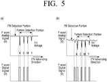
- an amount of light emitted from the light emitting unit 142 is set to be high while the color registration correction is performed, an amount of reflection of each color formed on the image forming medium increases.
- an amount of reflection of a yellow pattern which is bright color, noticeably increases and thus the yellow pattern may not be recognized as shown in part (a) of FIG. 5 .
- the light emitting unit 142 may be set to project an appropriate amount of light.
- a method for detecting an optimal amount of light of the light emitting unit 142 will be explained.
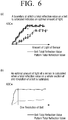
- FIG. 6 is a view to explain an optimal amount of light used by a registration sensor according to an exemplary embodiment.
- an amount of light at a time when the amount of light reflected from the image forming medium is saturated may be used for the color registration correction.
- an amount of light at a time when an amount of light reflected from a rotation section of the image forming medium is saturated may be calculated as shown in part (b) of FIG. 6 .
- an optimal amount of light may be calculated based on feedback on a state of one revolution of the image forming medium so that a portion in which an amount of reflection is reduced (a noise component: scratch on a belt and attachment of a toner) out of the whole area of the image forming medium does not affect the color registration correction.
- FIG. 7 parts (a) and (b), shows an amount of reflection per one revolution of the intermediate transfer belt to which toner is not attached, if an amount of light of the registration sensor increases
- FIG. 8 parts (a) and (b), is an enlarged view of a portion of FIG. 7 , parts (a) and (b),.
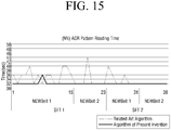
- FIGS. 11 to 15 are views illustrating results of experiments to test performance of a method for detecting an optimal amount of light according to an exemplary embodiment.
- FIGS. 11 to 13 illustrate a result of an experiment conducted using a color registration operation according to the present embodiment and a related-art color registration operation at a low temperature and a low humidity level.
- FIGS. 14 and 15 illustrate a result of an experiment conducted using the color registration operation according to the present embodiment and the related-art color registration operation at a high temperature and a high humidity level.
- a failure rate of the color registration operation and a retry rate of the color registration operation are noticeably reduced in comparison with the related-art method.
- a condition of the intermediate transfer belt is not good, color registration may not be performed in the related-art method.
- the feedback control method according to the present embodiment can achieve color registration.
- a retry rate of the color registration operation is noticeably reduced in comparison with the related-art.
- FIG. 16 is a flowchart illustrating a method for color registration according to an exemplary embodiment.
- color registration it is determined whether color registration is needed or not (S1610). More specifically, if a printing operation is performed in the image forming apparatus as much as a predetermined number of copies or if a command to perform color registration is input by a user, it is determined that color registration is needed.
- an optimal amount of light of the color registration sensor is set in a feedback manner (S1620). A detailed operation of setting the optimal amount of light will be explained below with reference to FIG. 17 .
- color registration correction is performed (S1630). More specifically, a predetermined mark for the color registration correction is formed and the color registration correction is performed with respect the mark using the optimal amount of light.
- FIG. 17 is a flowchart illustrating the method for setting the optimal amount of light of FIG. 16 in detail.
- an image forming medium is rotated.
- a predetermined initial control signal is provided to a registration sensor and the registration sensor senses an amount of light reflected from the image forming medium out of the light emitted in response to the initial control signal.
- a control signal to be input to the registration sensor is calculated according to a difference between the sensed amount of light and a predetermined target amount of light (S1710).
- the target amount of light refers to an amount of light at a time when the amount of light reflected from the image forming medium is saturated.
- the calculated control signal is provided to the registration sensor and the above-described operations are repeated (S1730). In other words, a feedback control is performed as shown in FIG. 3 .
- the calculated control signal and an amount of light sensed in response to the calculated control signal are stored (S1730).
- an amount of light of the registration sensor corresponding to the calculated maximum value is set as a reference amount of light (S1770).
- an amount of light of the registration sensor corresponding to the calculated average value may be set as a reference amount of light.
- an amount of light obtained by adding a predetermined offset value to an amount of light of the registration sensor corresponding to the calculated average value is set as a reference amount of light (S1780).
- an optimal amount of light of the registration sensor can be set swiftly. Also, since the condition of the image forming medium is considered in adjusting the reference amount of light, the color registration correction can be performed using the more robust optimal amount of light.
- the color registration method of FIGS. 16 and 17 may be performed in the image forming apparatus 100 shown in FIG. 1 and also may be performed any other image forming apparatus.
Landscapes
- Physics & Mathematics (AREA)
- General Physics & Mathematics (AREA)
- Engineering & Computer Science (AREA)
- Microelectronics & Electronic Packaging (AREA)
- Color Electrophotography (AREA)
- Control Or Security For Electrophotography (AREA)
Claims (14)
- Farbregistrierungsverfahren einer Bilderzeugungsvorrichtung (100), die einen Registrierungssensor (141) umfasst, wobei das Farbregistrierungsverfahren Folgendes umfasst:Bestimmen, ob Farbregistrierung benötigt wird oder nicht;wenn Farbregistrierung benötigt wird, Einstellen einer optimalen Lichtmenge des Registrierungssensors (141) auf eine Rückkopplungsweise;Ausbilden einer vorbestimmten Markierung zur Farbregistrierungskorrektur auf einem Bilderzeugungsmedium (180); undDurchführen einer Farbregistrierungskorrektur in Bezug auf die ausgebildete Markierung unter Verwendung der eingestellten optimalen Lichtmenge;wobei die Rückkopplungsweise eine Lichtmenge des Registrierungssensors derart anpasst, dass eine erfasste Lichtmenge auf eine vorbestimmte Ziellichtmenge angepasst wird;wobei das Einstellen der optimalen Lichtmenge während eines Drehens des Bilderzeugungsmediums durchgeführt wird und durch Folgendes gekennzeichnet ist:Bereitstellen eines vorbestimmten anfänglichen Steuersignals an den Registrierungssensor (141);Erfassen einer von dem Bilderzeugungsmedium (180) reflektierten Lichtmenge;Berechnen eines Steuersignals gemäß einer Differenz zwischen der erfassten Lichtmenge und einer vorbestimmten Ziellichtmenge;Bestimmen, durch Vergleichen der erfassten Lichtmenge und der Ziellichtmenge, ob eine Lichtmenge des Registrierungssensors einen stabilen Wert aufweist oder nicht;wenn die Lichtmenge des Registrierungssensors den stabilen Wert aufweist, Auswählen einer Lichtmenge des Registrierungssensors (141), die der erfassten Lichtmenge entspricht, als die optimale Lichtmenge; undBereitstellen des berechneten Steuersignals an den Registrierungssensor (141).
- Verfahren nach Anspruch 1, wobei die Ziellichtmenge eine Lichtmenge zu einem Zeitpunkt ist, an dem die von dem Bilderzeugungsmedium (180) reflektierte Lichtmenge gesättigt ist.
- Verfahren nach Anspruch 1 oder 2, wobei das Berechnen des Steuersignals das Berechnen des Steuersignals gemäß der erfassten Lichtmenge und der Ziellichtmenge unter Verwendung eines Proportional-lntegral(PI)-Reglers und/oder eines Proportional-Integral-Differential(PID)-Reglers umfasst.
- Verfahren nach einem der vorhergehenden Ansprüche, wobei das Einstellen der optimalen Lichtmenge ferner das Speichern des berechneten Steuersignals und einer Lichtmenge umfasst, die als Reaktion auf das berechnete Steuersignal erfasst wird.
- Verfahren nach Anspruch 4, wobei das Einstellen der optimalen Lichtmenge ferner Folgendes umfasst:Berechnen eines Durchschnittswerts der erfassten Lichtmenge und eines Höchstwerts der erfassten Lichtmenge unter Verwendung der gespeicherten Lichtmenge; undVergleichen des berechneten Durchschnittswerts und des berechneten Höchstwerts, wobei das Auswählen der Lichtmenge Folgendes umfasst: wenn eine Differenz zwischen dem berechneten Höchstwert und dem berechneten Durchschnittswert kleiner als ein vorbestimmter Wert ist, Auswählen einer Lichtmenge des Registrierungssensors (141), die dem berechneten Höchstwert entspricht, als die optimale Lichtmenge, und, wenn die Differenz zwischen dem berechneten Höchstwert und dem berechneten Durchschnittswert größer als der vorbestimmte Wert ist, Auswählen einer Lichtmenge, die durch Hinzufügen eines vorbestimmten Versatzwerts zu einer Lichtmenge des Registrierungssensors (141), die dem berechneten Durchschnittswert entspricht, erhalten wird, als die optimale Lichtmenge.
- Verfahren nach Anspruch 5, wobei das Auswählen der Lichtmenge Folgendes umfasst: wenn die Differenz zwischen dem berechneten Höchstwert und dem berechneten Durchschnittswert kleiner als der vorbestimmte Wert ist, Auswählen einer Lichtmenge des Registrierungssensors, die dem Durchschnittswert entspricht, als die optimale Lichtmenge.
- Verfahren nach einem der vorhergehenden Ansprüche, wobei das Bilderzeugungsmedium ein organischer Fotoleiter, ein Zwischenübertragungsband und/oder ein Papiertransportband ist.
- Bilderzeugungsvorrichtung (100), die Folgendes umfasst:eine Steuerung (170), die bestimmt, ob Farbregistrierung benötigt wird oder nicht;eine Farbregistrierungseinheit (150), die, wenn Farbregistrierung benötigt wird, konfiguriert ist, um eine optimale Lichtmenge eines Registrierungssensors (141) durch Durchführen einer Rückkopplungssteuerung einzustellen; undeine Bilderzeugungseinheit (160), die eine vorbestimmte Markierung zur Farbregistrierungskorrektur auf einem Bilderzeugungsmedium (180) ausbildet,wobei die Farbregistrierungseinheit (150) eine Farbregistrierungskorrektur in Bezug auf die ausgebildete Markierung unter Verwendung der eingestellten optimalen Lichtmenge durchführt;wobei die Rückkopplungssteuerung eine Lichtmenge des Registrierungssensors derart anpasst, dass eine erfasste Lichtmenge auf eine vorbestimmte Ziellichtmenge angepasst wird;wobei die Farbregistrierungseinheit konfiguriert ist, die optimale Lichtmenge einzustellen, während das Bilderzeugungsmedium gedreht wird, und dadurch gekennzeichnet ist, dass die Einstellung Folgendes umfasst:Bereitstellen eines vorbestimmten anfänglichen Steuersignals an den Registrierungssensor (141);Erfassen einer von dem Bilderzeugungsmedium (180) reflektierten Lichtmenge;Berechnen eines Steuersignals gemäß einer Differenz zwischen der erfassten Lichtmenge und einer vorbestimmten Ziellichtmenge;Bestimmen, durch Vergleichen der erfassten Lichtmenge und der Ziellichtmenge, ob eine Lichtmenge des Registrierungssensors einen stabilen Wert aufweist oder nicht;wenn die Lichtmenge des Registrierungssensors den stabilen Wert aufweist, Auswählen einer Lichtmenge des Registrierungssensors (141), die der erfassten Lichtmenge entspricht, als die optimale Lichtmenge; undBereitstellen des berechneten Steuersignals an den Registrierungssensor (141).
- Bilderzeugungsvorrichtung nach Anspruch 8, wobei die Ziellichtmenge eine Lichtmenge zu einem Zeitpunkt ist, an dem die von dem Bilderzeugungsmedium (180) reflektierte Lichtmenge gesättigt ist.
- Bilderzeugungsvorrichtung nach Anspruch 8 oder 9, wobei das Berechnen des Steuersignals das Berechnen des Steuersignals gemäß der erfassten Lichtmenge und der Ziellichtmenge unter Verwendung eines Proportional-lntegral(PI)-Reglers und/oder eines Proportional-Integral-Differential(PID)-Reglers umfasst.
- Bilderzeugungsvorrichtung nach einem der Ansprüche 7 bis 10, die ferner eine Speichereinheit (120) umfasst, die das berechnete Steuersignal und eine als Reaktion auf das berechnete Steuersignal erfasste Lichtmenge speichert.
- Bilderzeugungsvorrichtung nach Anspruch 11, wobei die Farbregistrierungseinheit (150) unter Verwendung der gespeicherten Lichtmenge einen Durchschnittswert der erfassten Lichtmenge und einen Höchstwert der erfassten Lichtmenge berechnet, eine Lichtmenge der Registrierungssensoreinheit (141), die dem berechneten Höchstwert entspricht, als die optimale Lichtmenge auswählt, wenn eine Differenz zwischen dem berechneten Höchstwert und dem berechneten Durchschnittswert kleiner als ein vorbestimmter Wert ist, und eine Lichtmenge des Registrierungssensors (141), die durch Hinzufügen eines vorbestimmten Versatzwerts zu einer Lichtmenge des Registrierungssensors (141), die dem berechneten Durchschnittswert entspricht, erhalten wird, als die optimale Lichtmenge auswählt, wenn die Differenz zwischen dem berechneten Höchstwert und dem berechneten Durchschnittswert größer als der vorbestimmte Wert ist.
- Bilderzeugungsvorrichtung nach Anspruch 12, wobei, wenn die Differenz zwischen dem berechneten Höchstwert und dem berechneten Durchschnittswert kleiner als der vorbestimmte Wert ist, die Farbregistrierungseinheit (150) eine Lichtmenge der Registrierungssensoreinheit (141), die dem berechneten Durchschnittswert entspricht, als die optimale Lichtmenge auswählt.
- Bilderzeugungsvorrichtung nach einem der Ansprüche 8 bis 13, wobei das Bilderzeugungsmedium ein organischer Fotoleiter, ein Zwischenübertragungsband und/oder ein Papiertransportband ist.
Applications Claiming Priority (1)
| Application Number | Priority Date | Filing Date | Title |
|---|---|---|---|
| KR1020110019123A KR101866805B1 (ko) | 2011-03-03 | 2011-03-03 | 화상형성장치 및 칼라 레지스트레이션 보정 방법 |
Publications (3)
| Publication Number | Publication Date |
|---|---|
| EP2495617A2 EP2495617A2 (de) | 2012-09-05 |
| EP2495617A3 EP2495617A3 (de) | 2015-12-09 |
| EP2495617B1 true EP2495617B1 (de) | 2021-01-13 |
Family
ID=44925322
Family Applications (1)
| Application Number | Title | Priority Date | Filing Date |
|---|---|---|---|
| EP11185459.2A Not-in-force EP2495617B1 (de) | 2011-03-03 | 2011-10-17 | Bilderzeugungsvorrichtung und Verfahren für die Farbregistrierungsberichtigung |
Country Status (3)
| Country | Link |
|---|---|
| US (1) | US9052666B2 (de) |
| EP (1) | EP2495617B1 (de) |
| KR (1) | KR101866805B1 (de) |
Families Citing this family (4)
| Publication number | Priority date | Publication date | Assignee | Title |
|---|---|---|---|---|
| JP5488450B2 (ja) * | 2010-12-24 | 2014-05-14 | ブラザー工業株式会社 | 画像形成装置 |
| KR20120127052A (ko) * | 2011-05-13 | 2012-11-21 | 삼성전자주식회사 | 화상형성장치 및 칼라 레지스트레이션 보정 방법 |
| JP6452319B2 (ja) * | 2014-05-23 | 2019-01-16 | キヤノン株式会社 | 画像形成装置 |
| FI128367B (en) * | 2018-05-28 | 2020-04-15 | Oura Health Oy | OPTICAL SENSOR SYSTEM FOR WEARABLE EQUIPMENT, METHOD FOR CONTROLLING THE OPERATION OF THE OPTICAL SENSOR SYSTEM, AND THE CORRESPONDING COMPUTER SOFTWARE PRODUCT |
Family Cites Families (8)
| Publication number | Priority date | Publication date | Assignee | Title |
|---|---|---|---|---|
| JP2004010251A (ja) * | 2002-06-06 | 2004-01-15 | Canon Inc | 画像形成方法及び装置 |
| JP2006234941A (ja) * | 2005-02-22 | 2006-09-07 | Fuji Xerox Co Ltd | 画像形成装置 |
| JP5162829B2 (ja) * | 2006-01-19 | 2013-03-13 | 富士ゼロックス株式会社 | 画像形成装置およびその画像処理方法 |
| JP4850651B2 (ja) * | 2006-10-12 | 2012-01-11 | キヤノン株式会社 | 画像形成装置 |
| JP5094298B2 (ja) * | 2007-09-14 | 2012-12-12 | キヤノン株式会社 | カラー画像形成装置、カラー画像形成装置における色調整方法 |
| US8204416B2 (en) * | 2008-12-02 | 2012-06-19 | Xerox Corporation | Method and apparatus for measuring color-to-color registration |
| JP4883148B2 (ja) * | 2009-07-25 | 2012-02-22 | コニカミノルタビジネステクノロジーズ株式会社 | 画像形成装置 |
| US8213816B2 (en) * | 2009-08-27 | 2012-07-03 | Xerox Corporation | Method and system for banding compensation using electrostatic voltmeter based sensing |
-
2011
- 2011-03-03 KR KR1020110019123A patent/KR101866805B1/ko not_active Expired - Fee Related
- 2011-10-17 EP EP11185459.2A patent/EP2495617B1/de not_active Not-in-force
-
2012
- 2012-02-21 US US13/401,391 patent/US9052666B2/en active Active
Non-Patent Citations (1)
| Title |
|---|
| None * |
Also Published As
| Publication number | Publication date |
|---|---|
| EP2495617A3 (de) | 2015-12-09 |
| KR101866805B1 (ko) | 2018-06-18 |
| US9052666B2 (en) | 2015-06-09 |
| KR20120100317A (ko) | 2012-09-12 |
| US20120224891A1 (en) | 2012-09-06 |
| EP2495617A2 (de) | 2012-09-05 |
Similar Documents
| Publication | Publication Date | Title |
|---|---|---|
| KR102144316B1 (ko) | 화상형성장치 및 컬러 레지스트레이션 보정 방법 | |
| EP2685315B1 (de) | Bilderzeugungsvorrichtung zur Durchführung von Registrierung und Dichtekorrektursteuerung | |
| US20110052231A1 (en) | Image forming apparatus and detecting method of pattern image regarding image quality adjustment | |
| US9052666B2 (en) | Image forming apparatus and method for color registration correction | |
| JP2007102189A (ja) | 色ずれ補正装置、色ずれ補正方法、画像形成装置、色ずれ補正プログラム及び記録媒体 | |
| US9354574B2 (en) | Method of controlling performance of auto color registration and image forming apparatus using the same | |
| JP6046945B2 (ja) | 画像形成装置 | |
| US8964248B2 (en) | Image forming apparatus and method for color registration adjustment | |
| US9316983B2 (en) | Image forming apparatus including first detection sensor and second detection sensor for detecting density detection pattern | |
| JP4835706B2 (ja) | 画像形成装置 | |
| US9207554B2 (en) | Image forming apparatus having improved image quality | |
| US9164455B2 (en) | Image forming apparatus | |
| US9158224B2 (en) | Image forming apparatus generating horizontal synchronization signals and method of image forming | |
| US9880497B2 (en) | Image forming device, position shift correction method, and recording medium | |
| US20150154477A1 (en) | Image forming apparatus, method for calibrating print density, and computer-readable recording medium | |
| JP6260271B2 (ja) | 画像形成装置 | |
| JP2004213032A (ja) | 画像形成装置および画像形成装置の色ずれ検知処理方法 | |
| US9323172B2 (en) | Image forming apparatus provided with image formation position correction function | |
| JP4890324B2 (ja) | 画像形成装置 | |
| JP4639710B2 (ja) | 画像形成装置 | |
| JP2004101889A (ja) | カラー画像形成装置の色ずれ補正装置 | |
| JP4595460B2 (ja) | 画像形成装置 | |
| JP2012058382A (ja) | 画像形成装置および色ずれ補正制御プログラム | |
| KR20090011759A (ko) | 자동 색상 정합을 수행하는 화상형성장치 및 그 방법 | |
| JP2019078926A (ja) | 画像形成装置 |
Legal Events
| Date | Code | Title | Description |
|---|---|---|---|
| PUAI | Public reference made under article 153(3) epc to a published international application that has entered the european phase |
Free format text: ORIGINAL CODE: 0009012 |
|
| AK | Designated contracting states |
Kind code of ref document: A2 Designated state(s): AL AT BE BG CH CY CZ DE DK EE ES FI FR GB GR HR HU IE IS IT LI LT LU LV MC MK MT NL NO PL PT RO RS SE SI SK SM TR |
|
| AX | Request for extension of the european patent |
Extension state: BA ME |
|
| RAP1 | Party data changed (applicant data changed or rights of an application transferred) |
Owner name: SAMSUNG ELECTRONICS CO., LTD. |
|
| PUAL | Search report despatched |
Free format text: ORIGINAL CODE: 0009013 |
|
| AK | Designated contracting states |
Kind code of ref document: A3 Designated state(s): AL AT BE BG CH CY CZ DE DK EE ES FI FR GB GR HR HU IE IS IT LI LT LU LV MC MK MT NL NO PL PT RO RS SE SI SK SM TR |
|
| AX | Request for extension of the european patent |
Extension state: BA ME |
|
| RIC1 | Information provided on ipc code assigned before grant |
Ipc: G03G 15/00 20060101AFI20151102BHEP |
|
| 17P | Request for examination filed |
Effective date: 20160526 |
|
| RBV | Designated contracting states (corrected) |
Designated state(s): AL AT BE BG CH CY CZ DE DK EE ES FI FR GB GR HR HU IE IS IT LI LT LU LV MC MK MT NL NO PL PT RO RS SE SI SK SM TR |
|
| RAP1 | Party data changed (applicant data changed or rights of an application transferred) |
Owner name: S-PRINTING SOLUTION CO., LTD. |
|
| RAP1 | Party data changed (applicant data changed or rights of an application transferred) |
Owner name: HP PRINTING KOREA CO., LTD. |
|
| STAA | Information on the status of an ep patent application or granted ep patent |
Free format text: STATUS: EXAMINATION IS IN PROGRESS |
|
| RAP1 | Party data changed (applicant data changed or rights of an application transferred) |
Owner name: HEWLETT-PACKARD DEVELOPMENT COMPANY, L.P. |
|
| 17Q | First examination report despatched |
Effective date: 20191128 |
|
| GRAP | Despatch of communication of intention to grant a patent |
Free format text: ORIGINAL CODE: EPIDOSNIGR1 |
|
| STAA | Information on the status of an ep patent application or granted ep patent |
Free format text: STATUS: GRANT OF PATENT IS INTENDED |
|
| INTG | Intention to grant announced |
Effective date: 20201028 |
|
| GRAS | Grant fee paid |
Free format text: ORIGINAL CODE: EPIDOSNIGR3 |
|
| GRAA | (expected) grant |
Free format text: ORIGINAL CODE: 0009210 |
|
| STAA | Information on the status of an ep patent application or granted ep patent |
Free format text: STATUS: THE PATENT HAS BEEN GRANTED |
|
| AK | Designated contracting states |
Kind code of ref document: B1 Designated state(s): AL AT BE BG CH CY CZ DE DK EE ES FI FR GB GR HR HU IE IS IT LI LT LU LV MC MK MT NL NO PL PT RO RS SE SI SK SM TR |
|
| REG | Reference to a national code |
Ref country code: GB Ref legal event code: FG4D |
|
| REG | Reference to a national code |
Ref country code: CH Ref legal event code: EP |
|
| REG | Reference to a national code |
Ref country code: DE Ref legal event code: R096 Ref document number: 602011069946 Country of ref document: DE |
|
| REG | Reference to a national code |
Ref country code: IE Ref legal event code: FG4D |
|
| REG | Reference to a national code |
Ref country code: AT Ref legal event code: REF Ref document number: 1355021 Country of ref document: AT Kind code of ref document: T Effective date: 20210215 |
|
| REG | Reference to a national code |
Ref country code: AT Ref legal event code: MK05 Ref document number: 1355021 Country of ref document: AT Kind code of ref document: T Effective date: 20210113 |
|
| REG | Reference to a national code |
Ref country code: NL Ref legal event code: MP Effective date: 20210113 |
|
| REG | Reference to a national code |
Ref country code: LT Ref legal event code: MG9D |
|
| PG25 | Lapsed in a contracting state [announced via postgrant information from national office to epo] |
Ref country code: NL Free format text: LAPSE BECAUSE OF FAILURE TO SUBMIT A TRANSLATION OF THE DESCRIPTION OR TO PAY THE FEE WITHIN THE PRESCRIBED TIME-LIMIT Effective date: 20210113 Ref country code: NO Free format text: LAPSE BECAUSE OF FAILURE TO SUBMIT A TRANSLATION OF THE DESCRIPTION OR TO PAY THE FEE WITHIN THE PRESCRIBED TIME-LIMIT Effective date: 20210413 Ref country code: BG Free format text: LAPSE BECAUSE OF FAILURE TO SUBMIT A TRANSLATION OF THE DESCRIPTION OR TO PAY THE FEE WITHIN THE PRESCRIBED TIME-LIMIT Effective date: 20210413 Ref country code: LT Free format text: LAPSE BECAUSE OF FAILURE TO SUBMIT A TRANSLATION OF THE DESCRIPTION OR TO PAY THE FEE WITHIN THE PRESCRIBED TIME-LIMIT Effective date: 20210113 Ref country code: PT Free format text: LAPSE BECAUSE OF FAILURE TO SUBMIT A TRANSLATION OF THE DESCRIPTION OR TO PAY THE FEE WITHIN THE PRESCRIBED TIME-LIMIT Effective date: 20210513 Ref country code: HR Free format text: LAPSE BECAUSE OF FAILURE TO SUBMIT A TRANSLATION OF THE DESCRIPTION OR TO PAY THE FEE WITHIN THE PRESCRIBED TIME-LIMIT Effective date: 20210113 Ref country code: FI Free format text: LAPSE BECAUSE OF FAILURE TO SUBMIT A TRANSLATION OF THE DESCRIPTION OR TO PAY THE FEE WITHIN THE PRESCRIBED TIME-LIMIT Effective date: 20210113 Ref country code: GR Free format text: LAPSE BECAUSE OF FAILURE TO SUBMIT A TRANSLATION OF THE DESCRIPTION OR TO PAY THE FEE WITHIN THE PRESCRIBED TIME-LIMIT Effective date: 20210414 |
|
| PG25 | Lapsed in a contracting state [announced via postgrant information from national office to epo] |
Ref country code: LV Free format text: LAPSE BECAUSE OF FAILURE TO SUBMIT A TRANSLATION OF THE DESCRIPTION OR TO PAY THE FEE WITHIN THE PRESCRIBED TIME-LIMIT Effective date: 20210113 Ref country code: RS Free format text: LAPSE BECAUSE OF FAILURE TO SUBMIT A TRANSLATION OF THE DESCRIPTION OR TO PAY THE FEE WITHIN THE PRESCRIBED TIME-LIMIT Effective date: 20210113 Ref country code: PL Free format text: LAPSE BECAUSE OF FAILURE TO SUBMIT A TRANSLATION OF THE DESCRIPTION OR TO PAY THE FEE WITHIN THE PRESCRIBED TIME-LIMIT Effective date: 20210113 Ref country code: AT Free format text: LAPSE BECAUSE OF FAILURE TO SUBMIT A TRANSLATION OF THE DESCRIPTION OR TO PAY THE FEE WITHIN THE PRESCRIBED TIME-LIMIT Effective date: 20210113 Ref country code: SE Free format text: LAPSE BECAUSE OF FAILURE TO SUBMIT A TRANSLATION OF THE DESCRIPTION OR TO PAY THE FEE WITHIN THE PRESCRIBED TIME-LIMIT Effective date: 20210113 |
|
| PG25 | Lapsed in a contracting state [announced via postgrant information from national office to epo] |
Ref country code: IS Free format text: LAPSE BECAUSE OF FAILURE TO SUBMIT A TRANSLATION OF THE DESCRIPTION OR TO PAY THE FEE WITHIN THE PRESCRIBED TIME-LIMIT Effective date: 20210513 |
|
| REG | Reference to a national code |
Ref country code: DE Ref legal event code: R097 Ref document number: 602011069946 Country of ref document: DE |
|
| PG25 | Lapsed in a contracting state [announced via postgrant information from national office to epo] |
Ref country code: CZ Free format text: LAPSE BECAUSE OF FAILURE TO SUBMIT A TRANSLATION OF THE DESCRIPTION OR TO PAY THE FEE WITHIN THE PRESCRIBED TIME-LIMIT Effective date: 20210113 Ref country code: EE Free format text: LAPSE BECAUSE OF FAILURE TO SUBMIT A TRANSLATION OF THE DESCRIPTION OR TO PAY THE FEE WITHIN THE PRESCRIBED TIME-LIMIT Effective date: 20210113 Ref country code: SM Free format text: LAPSE BECAUSE OF FAILURE TO SUBMIT A TRANSLATION OF THE DESCRIPTION OR TO PAY THE FEE WITHIN THE PRESCRIBED TIME-LIMIT Effective date: 20210113 |
|
| PLBE | No opposition filed within time limit |
Free format text: ORIGINAL CODE: 0009261 |
|
| STAA | Information on the status of an ep patent application or granted ep patent |
Free format text: STATUS: NO OPPOSITION FILED WITHIN TIME LIMIT |
|
| PG25 | Lapsed in a contracting state [announced via postgrant information from national office to epo] |
Ref country code: SK Free format text: LAPSE BECAUSE OF FAILURE TO SUBMIT A TRANSLATION OF THE DESCRIPTION OR TO PAY THE FEE WITHIN THE PRESCRIBED TIME-LIMIT Effective date: 20210113 Ref country code: ES Free format text: LAPSE BECAUSE OF FAILURE TO SUBMIT A TRANSLATION OF THE DESCRIPTION OR TO PAY THE FEE WITHIN THE PRESCRIBED TIME-LIMIT Effective date: 20210113 Ref country code: DK Free format text: LAPSE BECAUSE OF FAILURE TO SUBMIT A TRANSLATION OF THE DESCRIPTION OR TO PAY THE FEE WITHIN THE PRESCRIBED TIME-LIMIT Effective date: 20210113 Ref country code: RO Free format text: LAPSE BECAUSE OF FAILURE TO SUBMIT A TRANSLATION OF THE DESCRIPTION OR TO PAY THE FEE WITHIN THE PRESCRIBED TIME-LIMIT Effective date: 20210113 |
|
| 26N | No opposition filed |
Effective date: 20211014 |
|
| PG25 | Lapsed in a contracting state [announced via postgrant information from national office to epo] |
Ref country code: AL Free format text: LAPSE BECAUSE OF FAILURE TO SUBMIT A TRANSLATION OF THE DESCRIPTION OR TO PAY THE FEE WITHIN THE PRESCRIBED TIME-LIMIT Effective date: 20210113 |
|
| PG25 | Lapsed in a contracting state [announced via postgrant information from national office to epo] |
Ref country code: SI Free format text: LAPSE BECAUSE OF FAILURE TO SUBMIT A TRANSLATION OF THE DESCRIPTION OR TO PAY THE FEE WITHIN THE PRESCRIBED TIME-LIMIT Effective date: 20210113 |
|
| PG25 | Lapsed in a contracting state [announced via postgrant information from national office to epo] |
Ref country code: IT Free format text: LAPSE BECAUSE OF FAILURE TO SUBMIT A TRANSLATION OF THE DESCRIPTION OR TO PAY THE FEE WITHIN THE PRESCRIBED TIME-LIMIT Effective date: 20210113 |
|
| PG25 | Lapsed in a contracting state [announced via postgrant information from national office to epo] |
Ref country code: IS Free format text: LAPSE BECAUSE OF FAILURE TO SUBMIT A TRANSLATION OF THE DESCRIPTION OR TO PAY THE FEE WITHIN THE PRESCRIBED TIME-LIMIT Effective date: 20210513 |
|
| REG | Reference to a national code |
Ref country code: CH Ref legal event code: PL |
|
| REG | Reference to a national code |
Ref country code: BE Ref legal event code: MM Effective date: 20211031 |
|
| PG25 | Lapsed in a contracting state [announced via postgrant information from national office to epo] |
Ref country code: MC Free format text: LAPSE BECAUSE OF FAILURE TO SUBMIT A TRANSLATION OF THE DESCRIPTION OR TO PAY THE FEE WITHIN THE PRESCRIBED TIME-LIMIT Effective date: 20210113 |
|
| PG25 | Lapsed in a contracting state [announced via postgrant information from national office to epo] |
Ref country code: LU Free format text: LAPSE BECAUSE OF NON-PAYMENT OF DUE FEES Effective date: 20211017 Ref country code: BE Free format text: LAPSE BECAUSE OF NON-PAYMENT OF DUE FEES Effective date: 20211031 |
|
| PG25 | Lapsed in a contracting state [announced via postgrant information from national office to epo] |
Ref country code: LI Free format text: LAPSE BECAUSE OF NON-PAYMENT OF DUE FEES Effective date: 20211031 Ref country code: CH Free format text: LAPSE BECAUSE OF NON-PAYMENT OF DUE FEES Effective date: 20211031 |
|
| PG25 | Lapsed in a contracting state [announced via postgrant information from national office to epo] |
Ref country code: IE Free format text: LAPSE BECAUSE OF NON-PAYMENT OF DUE FEES Effective date: 20211017 |
|
| PGFP | Annual fee paid to national office [announced via postgrant information from national office to epo] |
Ref country code: GB Payment date: 20220922 Year of fee payment: 12 |
|
| PGFP | Annual fee paid to national office [announced via postgrant information from national office to epo] |
Ref country code: FR Payment date: 20220922 Year of fee payment: 12 |
|
| PGFP | Annual fee paid to national office [announced via postgrant information from national office to epo] |
Ref country code: DE Payment date: 20220616 Year of fee payment: 12 |
|
| PG25 | Lapsed in a contracting state [announced via postgrant information from national office to epo] |
Ref country code: HU Free format text: LAPSE BECAUSE OF FAILURE TO SUBMIT A TRANSLATION OF THE DESCRIPTION OR TO PAY THE FEE WITHIN THE PRESCRIBED TIME-LIMIT; INVALID AB INITIO Effective date: 20111017 Ref country code: CY Free format text: LAPSE BECAUSE OF FAILURE TO SUBMIT A TRANSLATION OF THE DESCRIPTION OR TO PAY THE FEE WITHIN THE PRESCRIBED TIME-LIMIT Effective date: 20210113 |
|
| PG25 | Lapsed in a contracting state [announced via postgrant information from national office to epo] |
Ref country code: MK Free format text: LAPSE BECAUSE OF FAILURE TO SUBMIT A TRANSLATION OF THE DESCRIPTION OR TO PAY THE FEE WITHIN THE PRESCRIBED TIME-LIMIT Effective date: 20210113 |
|
| REG | Reference to a national code |
Ref country code: DE Ref legal event code: R119 Ref document number: 602011069946 Country of ref document: DE |
|
| GBPC | Gb: european patent ceased through non-payment of renewal fee |
Effective date: 20231017 |
|
| PG25 | Lapsed in a contracting state [announced via postgrant information from national office to epo] |
Ref country code: TR Free format text: LAPSE BECAUSE OF FAILURE TO SUBMIT A TRANSLATION OF THE DESCRIPTION OR TO PAY THE FEE WITHIN THE PRESCRIBED TIME-LIMIT Effective date: 20210113 |
|
| PG25 | Lapsed in a contracting state [announced via postgrant information from national office to epo] |
Ref country code: GB Free format text: LAPSE BECAUSE OF NON-PAYMENT OF DUE FEES Effective date: 20231017 |
|
| PG25 | Lapsed in a contracting state [announced via postgrant information from national office to epo] |
Ref country code: GB Free format text: LAPSE BECAUSE OF NON-PAYMENT OF DUE FEES Effective date: 20231017 Ref country code: FR Free format text: LAPSE BECAUSE OF NON-PAYMENT OF DUE FEES Effective date: 20231031 Ref country code: DE Free format text: LAPSE BECAUSE OF NON-PAYMENT OF DUE FEES Effective date: 20240501 |
|
| PG25 | Lapsed in a contracting state [announced via postgrant information from national office to epo] |
Ref country code: MT Free format text: LAPSE BECAUSE OF FAILURE TO SUBMIT A TRANSLATION OF THE DESCRIPTION OR TO PAY THE FEE WITHIN THE PRESCRIBED TIME-LIMIT Effective date: 20210113 |