EP2495404B1 - Werkstückstütze eines Gasturbinentriebwerks - Google Patents
Werkstückstütze eines Gasturbinentriebwerks Download PDFInfo
- Publication number
- EP2495404B1 EP2495404B1 EP12154841.6A EP12154841A EP2495404B1 EP 2495404 B1 EP2495404 B1 EP 2495404B1 EP 12154841 A EP12154841 A EP 12154841A EP 2495404 B1 EP2495404 B1 EP 2495404B1
- Authority
- EP
- European Patent Office
- Prior art keywords
- workpiece
- arms
- receiving members
- arm
- support
- Prior art date
- Legal status (The legal status is an assumption and is not a legal conclusion. Google has not performed a legal analysis and makes no representation as to the accuracy of the status listed.)
- Active
Links
Images



Classifications
-
- B—PERFORMING OPERATIONS; TRANSPORTING
- B64—AIRCRAFT; AVIATION; COSMONAUTICS
- B64F—GROUND OR AIRCRAFT-CARRIER-DECK INSTALLATIONS SPECIALLY ADAPTED FOR USE IN CONNECTION WITH AIRCRAFT; DESIGNING, MANUFACTURING, ASSEMBLING, CLEANING, MAINTAINING OR REPAIRING AIRCRAFT, NOT OTHERWISE PROVIDED FOR; HANDLING, TRANSPORTING, TESTING OR INSPECTING AIRCRAFT COMPONENTS, NOT OTHERWISE PROVIDED FOR
- B64F5/00—Designing, manufacturing, assembling, cleaning, maintaining or repairing aircraft, not otherwise provided for; Handling, transporting, testing or inspecting aircraft components, not otherwise provided for
- B64F5/50—Handling or transporting aircraft components
-
- B—PERFORMING OPERATIONS; TRANSPORTING
- B23—MACHINE TOOLS; METAL-WORKING NOT OTHERWISE PROVIDED FOR
- B23Q—DETAILS, COMPONENTS, OR ACCESSORIES FOR MACHINE TOOLS, e.g. ARRANGEMENTS FOR COPYING OR CONTROLLING; MACHINE TOOLS IN GENERAL CHARACTERISED BY THE CONSTRUCTION OF PARTICULAR DETAILS OR COMPONENTS; COMBINATIONS OR ASSOCIATIONS OF METAL-WORKING MACHINES, NOT DIRECTED TO A PARTICULAR RESULT
- B23Q1/00—Members which are comprised in the general build-up of a form of machine, particularly relatively large fixed members
- B23Q1/25—Movable or adjustable work or tool supports
-
- B—PERFORMING OPERATIONS; TRANSPORTING
- B23—MACHINE TOOLS; METAL-WORKING NOT OTHERWISE PROVIDED FOR
- B23Q—DETAILS, COMPONENTS, OR ACCESSORIES FOR MACHINE TOOLS, e.g. ARRANGEMENTS FOR COPYING OR CONTROLLING; MACHINE TOOLS IN GENERAL CHARACTERISED BY THE CONSTRUCTION OF PARTICULAR DETAILS OR COMPONENTS; COMBINATIONS OR ASSOCIATIONS OF METAL-WORKING MACHINES, NOT DIRECTED TO A PARTICULAR RESULT
- B23Q1/00—Members which are comprised in the general build-up of a form of machine, particularly relatively large fixed members
- B23Q1/25—Movable or adjustable work or tool supports
- B23Q1/26—Movable or adjustable work or tool supports characterised by constructional features relating to the co-operation of relatively movable members; Means for preventing relative movement of such members
- B23Q1/267—Movable or adjustable work or tool supports characterised by constructional features relating to the co-operation of relatively movable members; Means for preventing relative movement of such members with means to prevent skewness between the relatively slidable members
-
- B—PERFORMING OPERATIONS; TRANSPORTING
- B23—MACHINE TOOLS; METAL-WORKING NOT OTHERWISE PROVIDED FOR
- B23Q—DETAILS, COMPONENTS, OR ACCESSORIES FOR MACHINE TOOLS, e.g. ARRANGEMENTS FOR COPYING OR CONTROLLING; MACHINE TOOLS IN GENERAL CHARACTERISED BY THE CONSTRUCTION OF PARTICULAR DETAILS OR COMPONENTS; COMBINATIONS OR ASSOCIATIONS OF METAL-WORKING MACHINES, NOT DIRECTED TO A PARTICULAR RESULT
- B23Q16/00—Equipment for precise positioning of tool or work into particular locations not otherwise provided for
- B23Q16/001—Stops, cams, or holders therefor
-
- B—PERFORMING OPERATIONS; TRANSPORTING
- B25—HAND TOOLS; PORTABLE POWER-DRIVEN TOOLS; MANIPULATORS
- B25B—TOOLS OR BENCH DEVICES NOT OTHERWISE PROVIDED FOR, FOR FASTENING, CONNECTING, DISENGAGING, OR HOLDING
- B25B11/00—Work holders not covered by any preceding group in the subclass, e.g. magnetic work holders, vacuum work holders
- B25B11/02—Assembly jigs
-
- B—PERFORMING OPERATIONS; TRANSPORTING
- B25—HAND TOOLS; PORTABLE POWER-DRIVEN TOOLS; MANIPULATORS
- B25B—TOOLS OR BENCH DEVICES NOT OTHERWISE PROVIDED FOR, FOR FASTENING, CONNECTING, DISENGAGING, OR HOLDING
- B25B5/00—Clamps
- B25B5/04—Clamps with pivoted jaws
-
- B—PERFORMING OPERATIONS; TRANSPORTING
- B25—HAND TOOLS; PORTABLE POWER-DRIVEN TOOLS; MANIPULATORS
- B25B—TOOLS OR BENCH DEVICES NOT OTHERWISE PROVIDED FOR, FOR FASTENING, CONNECTING, DISENGAGING, OR HOLDING
- B25B5/00—Clamps
- B25B5/14—Clamps for work of special profile
-
- B—PERFORMING OPERATIONS; TRANSPORTING
- B25—HAND TOOLS; PORTABLE POWER-DRIVEN TOOLS; MANIPULATORS
- B25H—WORKSHOP EQUIPMENT, e.g. FOR MARKING-OUT WORK; STORAGE MEANS FOR WORKSHOPS
- B25H1/00—Work benches; Portable stands or supports for positioning portable tools or work to be operated on thereby
- B25H1/0007—Work benches; Portable stands or supports for positioning portable tools or work to be operated on thereby for engines, motor-vehicles or bicycles
-
- B—PERFORMING OPERATIONS; TRANSPORTING
- B27—WORKING OR PRESERVING WOOD OR SIMILAR MATERIAL; NAILING OR STAPLING MACHINES IN GENERAL
- B27F—DOVETAILED WORK; TENONS; SLOTTING MACHINES FOR WOOD OR SIMILAR MATERIAL; NAILING OR STAPLING MACHINES
- B27F7/00—Nailing or stapling; Nailed or stapled work
- B27F7/15—Machines for driving in nail- plates and spiked fittings
- B27F7/155—Machines for driving in nail- plates and spiked fittings for nail plates
-
- F—MECHANICAL ENGINEERING; LIGHTING; HEATING; WEAPONS; BLASTING
- F01—MACHINES OR ENGINES IN GENERAL; ENGINE PLANTS IN GENERAL; STEAM ENGINES
- F01D—NON-POSITIVE DISPLACEMENT MACHINES OR ENGINES, e.g. STEAM TURBINES
- F01D25/00—Component parts, details, or accessories, not provided for in, or of interest apart from, other groups
- F01D25/28—Supporting or mounting arrangements, e.g. for turbine casing
- F01D25/285—Temporary support structures, e.g. for testing, assembling, installing, repairing; Assembly methods using such structures
-
- F—MECHANICAL ENGINEERING; LIGHTING; HEATING; WEAPONS; BLASTING
- F16—ENGINEERING ELEMENTS AND UNITS; GENERAL MEASURES FOR PRODUCING AND MAINTAINING EFFECTIVE FUNCTIONING OF MACHINES OR INSTALLATIONS; THERMAL INSULATION IN GENERAL
- F16M—FRAMES, CASINGS OR BEDS OF ENGINES, MACHINES OR APPARATUS, NOT SPECIFIC TO ENGINES, MACHINES OR APPARATUS PROVIDED FOR ELSEWHERE; STANDS; SUPPORTS
- F16M11/00—Stands or trestles as supports for apparatus or articles placed thereon ; Stands for scientific apparatus such as gravitational force meters
- F16M11/02—Heads
- F16M11/04—Means for attachment of apparatus; Means allowing adjustment of the apparatus relatively to the stand
- F16M11/041—Allowing quick release of the apparatus
Definitions
- the present disclosure relates to a workpiece support and particularly but not exclusively relates to a workpiece support for a gas turbine engine.
- Engines in particular gas turbine engines, may be supported during assembly, disassembly and maintenance of the constituent components.
- a previously-proposed stand 10 supporting a gas turbine engine 20 is shown in Figure 1(a) with an enlarged view of the stand 10 shown in Figure 1(b) . As depicted, there may be four stands 10, one in each corner of the gas turbine engine 20.
- each stand 10 may comprise a vertical slot 12 for receiving a corresponding pin 22 provided on the gas turbine engine 20.
- the pin 22 may be provided on a bracket 24, which may in turn be fastened to the engine 20.
- the engine 20 is lowered into the stands 10 so that the pins 22 align and engage with the slots 12 in the stands.
- the stands 10 and associated brackets 24 are unique to each engine 20. Accordingly, the prior art requires bespoke brackets 24 and/or stands 10 depending on the engine type. Therefore the stands and/or brackets must be changed if a different engine is to be worked on. Alternatively, only particular engines may be worked on in particular areas of the workshop. However, this does not facilitate modern manufacturing processes, which require flexibility in the use of manufacturing space and time.
- brackets 24 to be fastened to the engine 20. Not only does this take time, but the brackets 24 also increase the total engine weight, which is disadvantageous, particularly in the case of a jet engine.
- US2011/0204006 discloses a typical stand having a base and a supporting frame disposed perpendicularly to the base.
- the base and the supporting frame are hinged together at each location where the base and the supporting frame are coupled together.
- the stand also includes two supporting poles parallel to the supporting frame that support an engine component.
- the present disclosure therefore seeks to address these issues.
- a workpiece support for a gas turbine engine comprising: first and second arms pivotably connected to first and second support members respectively, the first and second support members being spaced apart, one or both of the first and second arms comprising first and second portions, the first portion comprising the first end of the arm and the second portion comprising the second end of the arm(110,120), wherein the first and second portions are angled with respect to one another, each arm comprising first and second receiving members for receiving a workpiece, the first and second receiving members being provided at first and second ends of each arm respectively, each arm being pivotably connected to the respective first and second support members at a point between the first and second ends of each arm, such that the workpiece is supported by the first and second receiving members of the first arm and the first and second receiving members of the second arm, wherein the angle between the first and second portions is adjustable.
- a point about which the arm pivots may be spaced apart from a line joining the first and second receiving members.
- One or both of the first and second arms may comprise first and second portions.
- the first portion may comprise the first end of the arm and the second portion may comprise the second end of the arm.
- the first and second portions may be angled with respect to one another.
- the first and second portions of the arm may not be parallel and they may be oblique.
- the first and second portions of the arm may be parallel.
- the angle between the first and second portions may be adjustable but locked in a set orientation during operation of the stand.
- the first and second arms and/or first and second receiving members may be removable from the workpiece support.
- the first and second arms and/or first and second receiving members may be interchangeable with alternative or replacement first and second arms and/or first and second receiving members.
- the first and second arms and/or first and second receiving members may be adjustable in size and/or shape, e.g. to accommodate different workpieces.
- the first and second arms may be adjustable in length.
- the first and second receiving members may be shaped to correspond with portions of the workpiece.
- the workpiece support may further comprise further arms with further first and second receiving members.
- the further arms may be arranged such that there are arms either side of the support members.
- a plurality of receiving members may be provided on each portion of the arm.
- the first and/or second arms may be biased, e.g. resiliently, into a receiving position, e.g. in which the arms are ready to receive the workpiece.
- the first and/or second arms may be biased into the receiving position by a resilient means, e.g. a spring, hydraulic ram arrangement or any other resilient means.
- the first and/or second arms may be biased into the receiving position by virtue of gravity, e.g. by the position of the arm pivot point with respect to the centre of gravity of the arm.
- the first and/or second receiving members may comprise securing means for securing the receiving members to the workpiece.
- the first and/or second receiving members may be mechanically fastened to the workpiece, e.g. by virtue of a screw thread or any other securing means.
- the first and/or second receiving members may be fixed, e.g. not movable, relative to the respective first and/or second arms.
- the first and/or second receiving members may be movable, e.g. pivotable, relative to the respective first and/or second arms.
- the workpiece support may further comprise one or more resilient means arranged to permit relative movement of the first and second receiving members.
- the resilient means may comprise a spring, an elastomeric, e.g. rubber, member, an elasto-hydrodynamic system or any other resilient means.
- the resilient means may reduce the risk of damaging the workpiece when positioning it on the workpiece support and/or increase the self adjustability of the system.
- One or both of the first and second arms may comprise three or more receiving members.
- the third and any further receiving members may be provided at a point intermediate of the first and second ends of the first and second arms.
- the workpiece support may be adapted to support workpieces of varying shapes and/or sizes.
- the workpiece support may be adapted to support an engine, for example a gas turbine engine.
- One or more of: the first and second support members, the first and second arms and the first and second receiving members may be electrically earthed.
- a workpiece support 100 may support a load, e.g. workpiece 102, for example, during assembly, disassembly or repair of the workpiece.
- the workpiece 102 may comprise an engine, in particular a gas turbine engine, or any other load requiring support.
- the workpiece support 100 may comprise first and second arms 110, 120 pivotably connected to first and second support members 112, 122 respectively.
- the first and second support members 112, 122 may comprise stands, pedestals or any other type of support member.
- the first and second support members 112, 122 may be laterally spaced apart.
- the support members 112, 122 may be braced to improve their stability.
- the support members 112, 122 may be fixed with respect to one another, e.g. they may both be fixed to the workshop floor 130 or they may be provided on a separate stand or base.
- the support members 112, 122 may also be earthed to ensure that the workpiece does not become electrically charged.
- the first arm 110 may comprise first and second receiving members 114a, 114b, e.g. support pads, for receiving the workpiece 102.
- the second arm 120 may also comprise first and second receiving members 124a, 124b, e.g. support pads, for receiving the workpiece 102.
- the first and second receiving members 114a, 114b, 124a, 124b may be connected to each other via the respective arm 110, 120 and the first and second receiving members may thus move as a pair.
- the first and second receiving members 114a, 114b, 124a, 124b may be shaped and/or sized to correspond with and receive the workpiece 102.
- the first and second receiving members may also comprise materials suitable to grip and/or conform to the workpiece.
- the first and second receiving members may be made from a resilient material, e.g. an elastomer such as rubber.
- the receiving members 114a, 114b, 124a, 124b may be configured to be mechanically fastened (e.g. by screw thread or similar) to the workpiece 102 in order to further improve the security of the workpiece 102.
- the first and second receiving members 114a, 114b, 124a, 124b may be provided at first and second ends of each arm respectively.
- the first receiving members 114a, 124a may be provided at first, e.g. upper, ends of the first and second arms 110, 120 and the second receiving members 114b, 124b may be provided at second, e.g. lower, ends of the first and second arms 110, 120.
- Each arm 110, 120 may be pivotably connected to the respective first and second support members 112, 122 at a pivot point 111, 121 between the first and second ends of each arm.
- the pivot point 111, 121 may be laterally offset from a line joining the first and second receiving members provided on a particular arm.
- the first arm may comprise first and second portions 110a, 110b and the first and second portions may be angled with respect to one another.
- the first portion 110a may comprise the first end of the arm and the second portion 110b may comprise the second end of the arm.
- the second arm 120 may comprise first and second portions 120a, 120b and the first and second portions may be angled with respect to one another.
- the first portion 120a may comprise the first end of the arm and the second portion 120b may comprise the second end of the arm.
- the workpiece 102 may be supported between the first and second receiving members 114a, 114b, of the first arm 110 and the first and second receiving members 124a, 124b of the second arm 120.
- the orientation of the first and second arms 110, 120 may adjust to support the workpiece.
- the first and second arms 110, 120 and their corresponding receiving members may self centre with respect to the workpiece.
- the workpiece support 100 of the present disclosure may accommodate workpieces having a range of shapes and sizes.
- the force imparted on the lower receiving members 114b, 124b may pivot the upper receiving members 114a, 124a closer towards the workpiece thereby securely clamping the workpiece 102 in place.
- the workpiece support 100 may further comprise a plurality of longitudinally spaced apart arms 110, 110', 110", 110"'.
- additional arms 110' may be connected to the same support member 112 and/or additional arms 110", 110"' may be connected to a further support member 112' longitudinally spaced apart from support member 112.
- the arms may be free to move independently of each other.
- the arms may be provided either side of the same support member.
- the relative position of the receiving members 114a, 114b with respect to each other may be adjustable.
- the position of the receiving members 114a, 114b may be tailored to the size, e.g. diameter, and/or shape of the workpiece 102 by altering the angle between the portions 110a, 110b of the arm 110 before the portions 110a, 110b of the arm 110 are locked together in their determined angle, e.g. by splines or any other mechanical locking means before mounting of he article in the workpiece support.
- the first and second portions of the arms may be unitary, i.e. they may be formed from a single piece of material, or they may be permanently locked together.
- the receiving members 114a, 114b and/or arm 110 may be adjustable in size and/or shape.
- the receiving members 114a, 114b and/or arm 110 may be tailored to the size and/or shape of the workpiece 102 before the arms are fixed in their determined arrangement before the workpiece is mounted.
- the receiving members 114a, 114b may be shaped to mate with specially designed or existing features in the workpiece to improve the security of the workpiece.
- the arm 110 may be sized to correspond to the shape and/or size of the workpiece, for example the arm 110 may be extendable in length.
- the receiving members 114a, 114b and/or arm 110 may be removable.
- the receiving members 114a, 114b and/or arm 110 may be interchanged with components of a different shape and/or size, e.g. for receiving a workpiece with a different geometry and/or size. Any and all adjustments between the arms are made before the arms are fixed in their determined position and the workpiece is mounted thereon.
- the receiving members 114a, 114b may be configured to move with respect to the arm 110.
- the receiving members 114a, 114b may pivot with respect to the arm 110 and the receiving members 114a, 114b may pivot in more than one plane with respect to the arm 110.
- the receiving members 114a, 114b may pivot about ball joints 115a, 115b provided between the arm 110 and each of the receiving members. The receiving members 114a, 114b may thus self locate with respect to the workpiece 102.
- the workpiece support 100 may further comprise one or more additional receiving members 114c, 114d. These additional receiving members 114c, 114d may be disposed at points between the pivot point 111 and either of the receiving members 114a, 114b. The additional receiving members 114c, 114d may better distribute the load from the workpiece 102 to the arm 110.
- one or more resilient means 116a, 116b, 116c, 116d may be incorporated into the workpiece support.
- the resilient means 116a, 116b, 116c, 116d may comprise one or more of a dashpot, a spring, an elastomer, e.g. rubber, an elasto-hydrodynamic system or any other resilient element.
- the resilient means may be configured to reduce the risk of damaging the workpiece 102 when positioning it on the workpiece support 100 and/or increase the self adjustability of the system. Accordingly, the resilient means may provide an element of damping to the system, e.g. so that the load imparted by the workpiece is gradually transferred to the workpiece support.
- the resilient means may be provided between one or more of the receiving members 114a, 114b, 114c, 114d and the arm 110.
- the arms of the workpiece support may be biased into a position ready to receive the workpiece.
- the second arm 120 may be resiliently biased, e.g. by a spring 126 disposed between the support member 122 and an end of the second arm.
- the spring shown may be a compressive spring (i.e. a spring acting under compression) connected to the lower end of the arm, however, a tensile spring (i.e. a spring acting under tension) may be connected to the upper end of the arm.
- the spring 126 ensures that when the workpiece 102 is removed the arm returns to a position ready to receive the next workpiece.
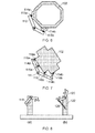
- Figure 8(a) shows how an unbiased arm 110 may default to a position which is not suitable for receiving the workpiece.
- the first arm 110 may also be biased in the same manner as the second arm 120.
- the first and/or second arms may be biased into the receiving position by virtue of gravity, e.g. by the position of the arm pivot point with respect to the centre of gravity of the arm, or by any other biasing means.
- the arms may be configured, e.g. shaped, to distribute the load of the workpiece 102.
- the arms 110, 110' may be shaped, e.g. splayed apart, in the longitudinal plane. This contrasts with the in line arrangement shown in Figure 9(a) .
- the arms depicted in Figure 9(b) may better distribute the load, e.g. in the case of a long workpiece or a workpiece with an off-centre centre of gravity.
- the arms 110, 120 may be shaped in the lateral plane.
- the arms 110, 120 may be curved or may comprise one or more angled portions and the arms may be tailored to the shape of the workpiece 102.
- the workpiece support of the present disclosure improves on the prior art by enabling the supports to be used with a wide range of workpieces, e.g. engines.
- the present disclosure may be applied to loads of vastly differing shapes, sizes and/or weights.
- the workpiece support of the present disclosure also removes the requirement for brackets fastened to the engine. Furthermore, there is an opportunity to reduce the time taken in supporting the engine as the stands and/or engine do not need to be positioned as accurately as required by the prior art. For example, the workpiece support disclosed herein is tolerant to unexpected changes in geometry of the load, e.g. an engine may be damaged in service such that the location points required by the previously-proposed stands are unusable.
- This workpiece support of the present disclosure may be used in any application where a load is to be supported. In particular, it may be used where the workpiece is liable to be damaged if its weight is not distributed evenly on supports.
Landscapes
- Engineering & Computer Science (AREA)
- Mechanical Engineering (AREA)
- General Engineering & Computer Science (AREA)
- Transportation (AREA)
- Manufacturing & Machinery (AREA)
- Aviation & Aerospace Engineering (AREA)
- Life Sciences & Earth Sciences (AREA)
- Forests & Forestry (AREA)
- Jigs For Machine Tools (AREA)
- Load-Engaging Elements For Cranes (AREA)
Claims (13)
- Werkstückstütze (100) für ein Gasturbinentriebwerk, umfassend:erste und zweite Arme (110, 120), die schwenkbar mit einem ersten bzw. zweiten Stützelementen (112, 122) verbunden sind, wobei das erste und das zweite Stützelement (112, 122) voneinander beabstandet sind, wobei einer oder beide der ersten und zweite Arme (110, 120) erste und zweite Abschnitte (110a, 110b: 120a, 120b) umfassen, wobei der erste Abschnitt (110a: 120a) das erste Ende des Arms (110, 120) und der zweite Abschnitt (110b, 120b) das zweite Ende des Arms (110, 120) umfasst, wobei die ersten und zweiten Abschnitte (110a, 110b: 120a, 120b) mit Bezug aufeinander winklig angeordnet sind;wobei jeder Arm erste und zweite Aufnahmeelemente (114a, 114b: 124a, 124b) umfasst, um ein Werkstück (102) aufzunehmen, wobei die ersten und zweiten Aufnahmeelement (114a, 114b: 124a, 124b) an ersten bzw. zweiten Enden (110, 120) jedes Arms bereitgestellt sind,wobei jeder Arm (110, 120) schwenkbar mit den entsprechenden ersten und zweiten Stützelementen (112, 122) an einem Punkt zwischen den ersten und den zweiten Enden jedes Arms (110, 120) verbunden ist, so dass das Werkstück (102) durch die ersten und zweiten Aufnahmeelemente (114a, 114b) des ersten Arms und der ersten und zweiten Aufnahmeelemente (124a, 124b) des zweiten Arms gestützt wird;dadurch gekennzeichnet, dassder Winkel zwischen den ersten und zweiten Abschnitten (110a, 110b: 120a, 120b) einstellbar ist.
- Werkstückstütze (100) nach einem der vorhergehenden Ansprüche, wobei die ersten und zweiten Arme (110, 120) und/oder die ersten und zweiten Aufnahmeelemente (114a, 114b: 124a, 124b) von der Werkstückstütze (100) entfernbar sind.
- Werkstückstütze (100) nach Anspruch 2, wobei die ersten und zweiten Arme (110, 120) und/oder die ersten und zweiten Aufnahmeelemente (114a, 114b: 124a, 124b) mit alternativen oder ersetzenden ersten und zweiten Armen (110, 120) und/oder ersten und zweiten Aufnahmeelementen (114a, 114b, 124a,124b: 124a, 124b) austauschbar sind,
- Werkstückstütze (100) nach einem der vorhergehenden Ansprüche, wobei die Werkstückstütze (100) weiter weitere Arme (110) mit weiteren ersten und zweiten Aufnahmeelementen (114c, 114d) umfasst, und wobei die weiteren Arme (110) derart angeordnet sind, dass auf beiden Seiten der Stützelemente Arme (112, 122) vorhanden sind.
- Werkstückstütze (100) nach einem der vorhergehenden Ansprüche, wobei die ersten und zweite Arme (110, 120) und/oder ersten und zweiten Aufnahmeelemente (114a, 114b, 124a, 124b) in der Größe und/oder Form einstellbar sind, um verschiedene Werkstücke (102) aufzunehmen.
- Werkstückstütze (100) nach einem der vorhergehenden Ansprüche, wobei die ersten und zweiten Arme (110, 120) in eine Aufnahmeposition vorgespannt sind.
- Werkstückstütze (100) nach einem der vorhergehenden Ansprüche, wobei die ersten und zweiten Aufnahmeelemente (114a, 114b; 124a, 124b) geformt sind, um Abschnitten des Werkstücks (102) zu entsprechen.
- Werkstückstütze (100) nach einem der vorhergehenden Ansprüche, wobei die ersten und zweiten Aufnahmeelemente (114a, 114b; 124a, 124b) Sicherungsmittel umfassen, um die Aufnahmeelemente an das Werkstück (102) zu sichern.
- Werkstückstütze (100) nach einem der vorhergehenden Ansprüche, wobei die ersten und/oder zweiten Aufnahmeelemente (114a, 114b: 124a, 124b) mit Bezug auf die entsprechenden ersten und/oder zweiten Arme (110, 120) fixiert sind.
- Werkstückstütze (100) nach einem der Ansprüche 1 bis 8, wobei die ersten und/oder zweiten Aufnahmeelemente (114a, 114b: 124a, 124b) mit Bezug auf die entsprechenden ersten und/oder zweiten Arme (110, 120) schwenkbar sind.
- Werkstückstütze (100) nach einem der vorhergehenden Ansprüche, wobei die Werkstückstütze (100) weiter ein oder mehrere elastische Mittel umfasst, die angeordnet sind, um eine relative Bewegung der ersten und zweiten Aufnahmeelemente (114a, 114b: 124a, 124b) zu ermöglichen.
- Werkstückstütze (100) nach einem der vorhergehenden Ansprüche, wobei einer oder beide der ersten und zweiten Arme (110, 120) drei oder mehr Aufnahmeelemente umfasst, wobei das dritte und alle weiteren Aufnahmeelemente an Zwischenpunkten der ersten und zweiten Enden der ersten und zweiten Arme (110, 120) bereitgestellt sind.
- Werkstückstütze (100) nach einem der vorhergehenden Ansprüche, wobei die Werkstückstütze (100) ausgelegt ist, um ein Triebwerk zu stützen.
Applications Claiming Priority (1)
| Application Number | Priority Date | Filing Date | Title |
|---|---|---|---|
| GB1103454.3A GB2488555C (en) | 2011-03-01 | 2011-03-01 | A workpiece support comprising pivotal arms |
Publications (2)
| Publication Number | Publication Date |
|---|---|
| EP2495404A1 EP2495404A1 (de) | 2012-09-05 |
| EP2495404B1 true EP2495404B1 (de) | 2015-04-08 |
Family
ID=43904347
Family Applications (1)
| Application Number | Title | Priority Date | Filing Date |
|---|---|---|---|
| EP12154841.6A Active EP2495404B1 (de) | 2011-03-01 | 2012-02-10 | Werkstückstütze eines Gasturbinentriebwerks |
Country Status (4)
| Country | Link |
|---|---|
| US (1) | US9022370B2 (de) |
| EP (1) | EP2495404B1 (de) |
| GB (1) | GB2488555C (de) |
| SG (1) | SG183631A1 (de) |
Families Citing this family (11)
| Publication number | Priority date | Publication date | Assignee | Title |
|---|---|---|---|---|
| US9115601B2 (en) * | 2012-01-06 | 2015-08-25 | Dresser-Rand Company | Turbomachine component alignment |
| JP6082285B2 (ja) * | 2013-03-14 | 2017-02-15 | 三菱日立パワーシステムズ株式会社 | 静翼環の取外・取付方法、及びこの方法に用いる静翼セグメントの補助支持装置 |
| FR3017112B1 (fr) * | 2014-02-03 | 2017-09-29 | Snecma | Structure de transport et de hissage pour turbomachine |
| WO2015168637A1 (en) * | 2014-05-02 | 2015-11-05 | Morey Joel T | Aircraft engine stand |
| FR3042481B1 (fr) * | 2015-10-16 | 2020-06-26 | Airbus (S.A.S.) | Outil de manutention |
| DE102018209890A1 (de) | 2018-06-19 | 2019-12-19 | MTU Aero Engines AG | Montageträger zum hängenden Aufnehmen einer Gasturbine |
| CN113580077A (zh) * | 2020-04-30 | 2021-11-02 | 中国航发商用航空发动机有限责任公司 | 一种支撑装置 |
| CN111648839A (zh) * | 2020-05-04 | 2020-09-11 | 嘉兴欧洛扬机械有限公司 | 一种内置保护罩的机油压力传感器 |
| CN112757240B (zh) * | 2021-01-18 | 2024-12-03 | 衡水中裕铁信装备工程有限公司 | 一种汽轮机叶片硬度测试调平支撑装置 |
| FR3126214B1 (fr) * | 2021-08-23 | 2024-07-12 | Safran Nacelles | Ensemble de manutention d’un cône d’éjection pour turboréacteur d’aéronef |
| US20260001660A1 (en) * | 2024-06-28 | 2026-01-01 | Pratt & Whitney Canada Corp. | Aircraft engine assembly stand |
Family Cites Families (26)
| Publication number | Priority date | Publication date | Assignee | Title |
|---|---|---|---|---|
| US1323127A (en) * | 1919-11-25 | Work-clamp | ||
| US490519A (en) * | 1893-01-24 | Picture-frame clamp | ||
| US1416760A (en) | 1920-07-03 | 1922-05-23 | Gen Electric | Elastic-fluid turbine or turbine-driven unit |
| US1781651A (en) * | 1927-04-22 | 1930-11-11 | Goodyear Tire & Rubber | Template for assembling strips of tire-chain material |
| US3268093A (en) | 1964-03-18 | 1966-08-23 | Gen Electric | Object handling system |
| FR2237060A1 (en) | 1973-07-13 | 1975-02-07 | Snecma | Jet engine mounting for aircraft - transmits propulsive force but accommodates differential expansion |
| EP0013772B1 (de) | 1979-01-24 | 1983-05-25 | BBC Aktiengesellschaft Brown, Boveri & Cie. | Vorrichtung zur Demontage von einer Rotor-Endschaufel |
| GB2045357B (en) | 1979-03-06 | 1982-11-10 | Westland Aircraft Ltd | Aircraft turbine engine mounting assembly |
| US4429861A (en) * | 1980-11-19 | 1984-02-07 | Range Alfred P | Tobacco leaf grading and stripping apparatus |
| US4539738A (en) * | 1982-09-01 | 1985-09-10 | Westinghouse Electric Corp. | Strap and vane positioning fixture for fuel rod grid and method |
| US4747588A (en) * | 1986-08-15 | 1988-05-31 | Dillhoff George A | Universal clamping tool |
| DE8807261U1 (de) * | 1988-06-06 | 1988-10-06 | Kurt Wurm, Werkzeugbau, 6101 Messel | Spannhand |
| GB2226522B (en) * | 1988-11-26 | 1993-01-06 | Calder Technical Services Ltd | Pipe restraining clamp |
| US5494553A (en) * | 1993-09-20 | 1996-02-27 | Colucci; William G. | Multi-purpose clamping apparatus |
| US6283361B1 (en) * | 1998-05-27 | 2001-09-04 | Calsonic Corporation | General-purpose jig |
| US6142460A (en) * | 1998-06-17 | 2000-11-07 | Irwin; Lawrence F. | Method and apparatus for installing and removing a sink mounted garbage disposer |
| US6224332B1 (en) | 1999-05-14 | 2001-05-01 | General Electric Co. | Apparatus and methods for installing, removing and adjusting an inner turbine shell section relative to an outer turbine shell section |
| US6874737B1 (en) * | 1999-08-03 | 2005-04-05 | Thomas Madelone | Universal fixture system and base therefor |
| US6439449B1 (en) * | 1999-12-20 | 2002-08-27 | Ephrem Gelfman | Assembling jig for sectional articles |
| GB2394940B (en) | 2002-10-16 | 2004-08-04 | Dennis Gentle | Cowl removal trolley |
| DE10258633A1 (de) * | 2002-12-16 | 2004-07-08 | Kuka Roboter Gmbh | Verfahren und Vorrichtung zum Positionieren von zusammenzufügenden Bauteilen |
| DE102004056286B4 (de) * | 2004-11-22 | 2015-12-24 | Airbus Operations Gmbh | Vorrichtung und Verfahren zum form- und/oder abmessungsunabhängigen Zusammenfügen und Heften von mehreren Einzelkomponenten zur Bildung von eigensteifen, transportfähigen Sektionen für Verkehrsmittel, insbesondere für Luftfahrzeuge |
| GB2460419B (en) | 2008-05-29 | 2010-09-22 | Rolls Royce Plc | A cradle arrangement |
| US8573576B2 (en) * | 2009-06-26 | 2013-11-05 | Intuitive Research And Technology Corporation | Clamp for single-handed operation |
| US9470108B2 (en) | 2010-02-22 | 2016-10-18 | American Airlines, Inc. | Thrust reverser cowl rack |
| US9469016B2 (en) * | 2010-09-14 | 2016-10-18 | Honda Motor Co., Ltd. | Vertically-oriented fixture for selectably holding dissimilar workpieces |
-
2011
- 2011-03-01 GB GB1103454.3A patent/GB2488555C/en active Active
-
2012
- 2012-02-10 EP EP12154841.6A patent/EP2495404B1/de active Active
- 2012-02-10 US US13/370,908 patent/US9022370B2/en active Active
- 2012-02-14 SG SG2012010310A patent/SG183631A1/en unknown
Also Published As
| Publication number | Publication date |
|---|---|
| GB2488555B (en) | 2013-09-18 |
| EP2495404A1 (de) | 2012-09-05 |
| GB201103454D0 (en) | 2011-04-13 |
| US9022370B2 (en) | 2015-05-05 |
| US20120223467A1 (en) | 2012-09-06 |
| SG183631A1 (en) | 2012-09-27 |
| GB2488555A (en) | 2012-09-05 |
| GB2488555C (en) | 2014-12-03 |
Similar Documents
| Publication | Publication Date | Title |
|---|---|---|
| EP2495404A1 (de) | Werkstückstütze eines Gasturbinentriebwerks | |
| US8061699B2 (en) | Clamping system | |
| US9816599B2 (en) | Modular transmission support | |
| KR101236132B1 (ko) | 송전선로 피뢰기설치용 고정금구 | |
| KR20180133518A (ko) | 측면 수직 거울 군 및 이의 설치 방법 | |
| CN106768754A (zh) | 振动试验夹具 | |
| US11208215B2 (en) | Method for mounting an aircraft pylon | |
| SE533630C2 (sv) | Inställbart fäste i strukturer | |
| US20130299311A1 (en) | Flip-able v-plow belt cleaner | |
| US9186762B2 (en) | Turbine extension nut support tool | |
| US9351565B2 (en) | Clamp for mounting of tray and tray assembly thereof | |
| CN214189469U (zh) | 一种消防管道运输装置 | |
| CN112166061A (zh) | 用于电力机车的可变的变压器保持设备 | |
| US20190249761A1 (en) | Modular transmission support | |
| CN102367912B (zh) | 分体式速换滑触悬挂装置 | |
| DK181302B1 (en) | Support Sling | |
| CN202419081U (zh) | 一种分体式速换滑触悬挂装置 | |
| US9551630B2 (en) | Device for fixing reactor modules to a test bench | |
| CN204802570U (zh) | 托辊支座、缓冲床及带式输送机 | |
| CN210014113U (zh) | 一种限位保护装置及刻蚀设备 | |
| CN211651775U (zh) | 称重支架 | |
| CN209730761U (zh) | 电缆固定装置 | |
| CN209467470U (zh) | 一种筒形结构件抱紧装置 | |
| CN223849223U (zh) | 一种适用于齿轮箱放置的工装 | |
| CN118225359A (zh) | 六自由度摇摆装置摇摆台试验件固定工装及安装方法 |
Legal Events
| Date | Code | Title | Description |
|---|---|---|---|
| PUAI | Public reference made under article 153(3) epc to a published international application that has entered the european phase |
Free format text: ORIGINAL CODE: 0009012 |
|
| AK | Designated contracting states |
Kind code of ref document: A1 Designated state(s): AL AT BE BG CH CY CZ DE DK EE ES FI FR GB GR HR HU IE IS IT LI LT LU LV MC MK MT NL NO PL PT RO RS SE SI SK SM TR |
|
| AX | Request for extension of the european patent |
Extension state: BA ME |
|
| 17P | Request for examination filed |
Effective date: 20130218 |
|
| RIC1 | Information provided on ipc code assigned before grant |
Ipc: B64F 5/00 20060101ALI20141016BHEP Ipc: F01D 25/28 20060101AFI20141016BHEP Ipc: F16M 11/04 20060101ALI20141016BHEP Ipc: B25H 1/00 20060101ALI20141016BHEP |
|
| GRAP | Despatch of communication of intention to grant a patent |
Free format text: ORIGINAL CODE: EPIDOSNIGR1 |
|
| INTG | Intention to grant announced |
Effective date: 20141202 |
|
| GRAS | Grant fee paid |
Free format text: ORIGINAL CODE: EPIDOSNIGR3 |
|
| GRAA | (expected) grant |
Free format text: ORIGINAL CODE: 0009210 |
|
| AK | Designated contracting states |
Kind code of ref document: B1 Designated state(s): AL AT BE BG CH CY CZ DE DK EE ES FI FR GB GR HR HU IE IS IT LI LT LU LV MC MK MT NL NO PL PT RO RS SE SI SK SM TR |
|
| REG | Reference to a national code |
Ref country code: GB Ref legal event code: FG4D |
|
| REG | Reference to a national code |
Ref country code: CH Ref legal event code: EP |
|
| REG | Reference to a national code |
Ref country code: IE Ref legal event code: FG4D |
|
| REG | Reference to a national code |
Ref country code: AT Ref legal event code: REF Ref document number: 720748 Country of ref document: AT Kind code of ref document: T Effective date: 20150515 |
|
| REG | Reference to a national code |
Ref country code: DE Ref legal event code: R096 Ref document number: 602012006401 Country of ref document: DE Effective date: 20150521 |
|
| RAP2 | Party data changed (patent owner data changed or rights of a patent transferred) |
Owner name: ROLLS-ROYCE PLC |
|
| REG | Reference to a national code |
Ref country code: AT Ref legal event code: MK05 Ref document number: 720748 Country of ref document: AT Kind code of ref document: T Effective date: 20150408 |
|
| REG | Reference to a national code |
Ref country code: NL Ref legal event code: VDEP Effective date: 20150408 |
|
| REG | Reference to a national code |
Ref country code: LT Ref legal event code: MG4D |
|
| PG25 | Lapsed in a contracting state [announced via postgrant information from national office to epo] |
Ref country code: NL Free format text: LAPSE BECAUSE OF FAILURE TO SUBMIT A TRANSLATION OF THE DESCRIPTION OR TO PAY THE FEE WITHIN THE PRESCRIBED TIME-LIMIT Effective date: 20150408 |
|
| PG25 | Lapsed in a contracting state [announced via postgrant information from national office to epo] |
Ref country code: LT Free format text: LAPSE BECAUSE OF FAILURE TO SUBMIT A TRANSLATION OF THE DESCRIPTION OR TO PAY THE FEE WITHIN THE PRESCRIBED TIME-LIMIT Effective date: 20150408 Ref country code: ES Free format text: LAPSE BECAUSE OF FAILURE TO SUBMIT A TRANSLATION OF THE DESCRIPTION OR TO PAY THE FEE WITHIN THE PRESCRIBED TIME-LIMIT Effective date: 20150408 Ref country code: PT Free format text: LAPSE BECAUSE OF FAILURE TO SUBMIT A TRANSLATION OF THE DESCRIPTION OR TO PAY THE FEE WITHIN THE PRESCRIBED TIME-LIMIT Effective date: 20150810 Ref country code: NO Free format text: LAPSE BECAUSE OF FAILURE TO SUBMIT A TRANSLATION OF THE DESCRIPTION OR TO PAY THE FEE WITHIN THE PRESCRIBED TIME-LIMIT Effective date: 20150708 Ref country code: HR Free format text: LAPSE BECAUSE OF FAILURE TO SUBMIT A TRANSLATION OF THE DESCRIPTION OR TO PAY THE FEE WITHIN THE PRESCRIBED TIME-LIMIT Effective date: 20150408 Ref country code: FI Free format text: LAPSE BECAUSE OF FAILURE TO SUBMIT A TRANSLATION OF THE DESCRIPTION OR TO PAY THE FEE WITHIN THE PRESCRIBED TIME-LIMIT Effective date: 20150408 |
|
| PG25 | Lapsed in a contracting state [announced via postgrant information from national office to epo] |
Ref country code: IS Free format text: LAPSE BECAUSE OF FAILURE TO SUBMIT A TRANSLATION OF THE DESCRIPTION OR TO PAY THE FEE WITHIN THE PRESCRIBED TIME-LIMIT Effective date: 20150808 Ref country code: AT Free format text: LAPSE BECAUSE OF FAILURE TO SUBMIT A TRANSLATION OF THE DESCRIPTION OR TO PAY THE FEE WITHIN THE PRESCRIBED TIME-LIMIT Effective date: 20150408 Ref country code: GR Free format text: LAPSE BECAUSE OF FAILURE TO SUBMIT A TRANSLATION OF THE DESCRIPTION OR TO PAY THE FEE WITHIN THE PRESCRIBED TIME-LIMIT Effective date: 20150709 Ref country code: LV Free format text: LAPSE BECAUSE OF FAILURE TO SUBMIT A TRANSLATION OF THE DESCRIPTION OR TO PAY THE FEE WITHIN THE PRESCRIBED TIME-LIMIT Effective date: 20150408 Ref country code: RS Free format text: LAPSE BECAUSE OF FAILURE TO SUBMIT A TRANSLATION OF THE DESCRIPTION OR TO PAY THE FEE WITHIN THE PRESCRIBED TIME-LIMIT Effective date: 20150408 |
|
| REG | Reference to a national code |
Ref country code: DE Ref legal event code: R097 Ref document number: 602012006401 Country of ref document: DE |
|
| PG25 | Lapsed in a contracting state [announced via postgrant information from national office to epo] |
Ref country code: DK Free format text: LAPSE BECAUSE OF FAILURE TO SUBMIT A TRANSLATION OF THE DESCRIPTION OR TO PAY THE FEE WITHIN THE PRESCRIBED TIME-LIMIT Effective date: 20150408 Ref country code: EE Free format text: LAPSE BECAUSE OF FAILURE TO SUBMIT A TRANSLATION OF THE DESCRIPTION OR TO PAY THE FEE WITHIN THE PRESCRIBED TIME-LIMIT Effective date: 20150408 |
|
| PLBE | No opposition filed within time limit |
Free format text: ORIGINAL CODE: 0009261 |
|
| STAA | Information on the status of an ep patent application or granted ep patent |
Free format text: STATUS: NO OPPOSITION FILED WITHIN TIME LIMIT |
|
| REG | Reference to a national code |
Ref country code: FR Ref legal event code: PLFP Year of fee payment: 5 |
|
| PG25 | Lapsed in a contracting state [announced via postgrant information from national office to epo] |
Ref country code: CZ Free format text: LAPSE BECAUSE OF FAILURE TO SUBMIT A TRANSLATION OF THE DESCRIPTION OR TO PAY THE FEE WITHIN THE PRESCRIBED TIME-LIMIT Effective date: 20150408 Ref country code: RO Free format text: LAPSE BECAUSE OF NON-PAYMENT OF DUE FEES Effective date: 20150408 Ref country code: SK Free format text: LAPSE BECAUSE OF FAILURE TO SUBMIT A TRANSLATION OF THE DESCRIPTION OR TO PAY THE FEE WITHIN THE PRESCRIBED TIME-LIMIT Effective date: 20150408 Ref country code: PL Free format text: LAPSE BECAUSE OF FAILURE TO SUBMIT A TRANSLATION OF THE DESCRIPTION OR TO PAY THE FEE WITHIN THE PRESCRIBED TIME-LIMIT Effective date: 20150408 |
|
| 26N | No opposition filed |
Effective date: 20160111 |
|
| PG25 | Lapsed in a contracting state [announced via postgrant information from national office to epo] |
Ref country code: IT Free format text: LAPSE BECAUSE OF FAILURE TO SUBMIT A TRANSLATION OF THE DESCRIPTION OR TO PAY THE FEE WITHIN THE PRESCRIBED TIME-LIMIT Effective date: 20150408 |
|
| REG | Reference to a national code |
Ref country code: DE Ref legal event code: R082 Ref document number: 602012006401 Country of ref document: DE Representative=s name: HERNANDEZ, YORCK, DIPL.-ING., DE |
|
| PG25 | Lapsed in a contracting state [announced via postgrant information from national office to epo] |
Ref country code: BE Free format text: LAPSE BECAUSE OF NON-PAYMENT OF DUE FEES Effective date: 20160229 Ref country code: SI Free format text: LAPSE BECAUSE OF FAILURE TO SUBMIT A TRANSLATION OF THE DESCRIPTION OR TO PAY THE FEE WITHIN THE PRESCRIBED TIME-LIMIT Effective date: 20150408 |
|
| PG25 | Lapsed in a contracting state [announced via postgrant information from national office to epo] |
Ref country code: BE Free format text: LAPSE BECAUSE OF FAILURE TO SUBMIT A TRANSLATION OF THE DESCRIPTION OR TO PAY THE FEE WITHIN THE PRESCRIBED TIME-LIMIT Effective date: 20150408 |
|
| PG25 | Lapsed in a contracting state [announced via postgrant information from national office to epo] |
Ref country code: MC Free format text: LAPSE BECAUSE OF FAILURE TO SUBMIT A TRANSLATION OF THE DESCRIPTION OR TO PAY THE FEE WITHIN THE PRESCRIBED TIME-LIMIT Effective date: 20150408 Ref country code: LU Free format text: LAPSE BECAUSE OF FAILURE TO SUBMIT A TRANSLATION OF THE DESCRIPTION OR TO PAY THE FEE WITHIN THE PRESCRIBED TIME-LIMIT Effective date: 20160210 |
|
| REG | Reference to a national code |
Ref country code: CH Ref legal event code: PL |
|
| PG25 | Lapsed in a contracting state [announced via postgrant information from national office to epo] |
Ref country code: LI Free format text: LAPSE BECAUSE OF NON-PAYMENT OF DUE FEES Effective date: 20160229 Ref country code: CH Free format text: LAPSE BECAUSE OF NON-PAYMENT OF DUE FEES Effective date: 20160229 |
|
| REG | Reference to a national code |
Ref country code: IE Ref legal event code: MM4A |
|
| PG25 | Lapsed in a contracting state [announced via postgrant information from national office to epo] |
Ref country code: IE Free format text: LAPSE BECAUSE OF NON-PAYMENT OF DUE FEES Effective date: 20160210 |
|
| REG | Reference to a national code |
Ref country code: FR Ref legal event code: PLFP Year of fee payment: 6 |
|
| PG25 | Lapsed in a contracting state [announced via postgrant information from national office to epo] |
Ref country code: SE Free format text: LAPSE BECAUSE OF FAILURE TO SUBMIT A TRANSLATION OF THE DESCRIPTION OR TO PAY THE FEE WITHIN THE PRESCRIBED TIME-LIMIT Effective date: 20150408 |
|
| PG25 | Lapsed in a contracting state [announced via postgrant information from national office to epo] |
Ref country code: MT Free format text: LAPSE BECAUSE OF FAILURE TO SUBMIT A TRANSLATION OF THE DESCRIPTION OR TO PAY THE FEE WITHIN THE PRESCRIBED TIME-LIMIT Effective date: 20150408 |
|
| REG | Reference to a national code |
Ref country code: FR Ref legal event code: PLFP Year of fee payment: 7 |
|
| PG25 | Lapsed in a contracting state [announced via postgrant information from national office to epo] |
Ref country code: SM Free format text: LAPSE BECAUSE OF FAILURE TO SUBMIT A TRANSLATION OF THE DESCRIPTION OR TO PAY THE FEE WITHIN THE PRESCRIBED TIME-LIMIT Effective date: 20150408 Ref country code: HU Free format text: LAPSE BECAUSE OF FAILURE TO SUBMIT A TRANSLATION OF THE DESCRIPTION OR TO PAY THE FEE WITHIN THE PRESCRIBED TIME-LIMIT; INVALID AB INITIO Effective date: 20120210 Ref country code: CY Free format text: LAPSE BECAUSE OF FAILURE TO SUBMIT A TRANSLATION OF THE DESCRIPTION OR TO PAY THE FEE WITHIN THE PRESCRIBED TIME-LIMIT Effective date: 20150408 |
|
| PG25 | Lapsed in a contracting state [announced via postgrant information from national office to epo] |
Ref country code: MT Free format text: LAPSE BECAUSE OF FAILURE TO SUBMIT A TRANSLATION OF THE DESCRIPTION OR TO PAY THE FEE WITHIN THE PRESCRIBED TIME-LIMIT Effective date: 20160229 Ref country code: MK Free format text: LAPSE BECAUSE OF FAILURE TO SUBMIT A TRANSLATION OF THE DESCRIPTION OR TO PAY THE FEE WITHIN THE PRESCRIBED TIME-LIMIT Effective date: 20150408 Ref country code: TR Free format text: LAPSE BECAUSE OF FAILURE TO SUBMIT A TRANSLATION OF THE DESCRIPTION OR TO PAY THE FEE WITHIN THE PRESCRIBED TIME-LIMIT Effective date: 20150408 |
|
| PG25 | Lapsed in a contracting state [announced via postgrant information from national office to epo] |
Ref country code: BG Free format text: LAPSE BECAUSE OF FAILURE TO SUBMIT A TRANSLATION OF THE DESCRIPTION OR TO PAY THE FEE WITHIN THE PRESCRIBED TIME-LIMIT Effective date: 20150408 |
|
| PG25 | Lapsed in a contracting state [announced via postgrant information from national office to epo] |
Ref country code: AL Free format text: LAPSE BECAUSE OF FAILURE TO SUBMIT A TRANSLATION OF THE DESCRIPTION OR TO PAY THE FEE WITHIN THE PRESCRIBED TIME-LIMIT Effective date: 20150408 |
|
| P01 | Opt-out of the competence of the unified patent court (upc) registered |
Effective date: 20230528 |
|
| PGFP | Annual fee paid to national office [announced via postgrant information from national office to epo] |
Ref country code: GB Payment date: 20260223 Year of fee payment: 15 |
|
| PGFP | Annual fee paid to national office [announced via postgrant information from national office to epo] |
Ref country code: DE Payment date: 20260220 Year of fee payment: 15 |
|
| PGFP | Annual fee paid to national office [announced via postgrant information from national office to epo] |
Ref country code: FR Payment date: 20260224 Year of fee payment: 15 |