EP2495078A1 - Werkzeugaufnahme - Google Patents
Werkzeugaufnahme Download PDFInfo
- Publication number
- EP2495078A1 EP2495078A1 EP12152075A EP12152075A EP2495078A1 EP 2495078 A1 EP2495078 A1 EP 2495078A1 EP 12152075 A EP12152075 A EP 12152075A EP 12152075 A EP12152075 A EP 12152075A EP 2495078 A1 EP2495078 A1 EP 2495078A1
- Authority
- EP
- European Patent Office
- Prior art keywords
- working axis
- locking
- sleeve
- tool holder
- link
- Prior art date
- Legal status (The legal status is an assumption and is not a legal conclusion. Google has not performed a legal analysis and makes no representation as to the accuracy of the status listed.)
- Granted
Links
Images




Classifications
-
- B—PERFORMING OPERATIONS; TRANSPORTING
- B23—MACHINE TOOLS; METAL-WORKING NOT OTHERWISE PROVIDED FOR
- B23B—TURNING; BORING
- B23B31/00—Chucks; Expansion mandrels; Adaptations thereof for remote control
- B23B31/02—Chucks
- B23B31/10—Chucks characterised by the retaining or gripping devices or their immediate operating means
- B23B31/107—Retention by laterally-acting detents, e.g. pins, screws, wedges; Retention by loose elements, e.g. balls
- B23B31/1071—Retention by balls
-
- B—PERFORMING OPERATIONS; TRANSPORTING
- B25—HAND TOOLS; PORTABLE POWER-DRIVEN TOOLS; MANIPULATORS
- B25D—PERCUSSIVE TOOLS
- B25D11/00—Portable percussive tools with electromotor or other motor drive
- B25D11/005—Arrangements for adjusting the stroke of the impulse member or for stopping the impact action when the tool is lifted from the working surface
-
- B—PERFORMING OPERATIONS; TRANSPORTING
- B25—HAND TOOLS; PORTABLE POWER-DRIVEN TOOLS; MANIPULATORS
- B25D—PERCUSSIVE TOOLS
- B25D17/00—Details of, or accessories for, portable power-driven percussive tools
- B25D17/08—Means for retaining and guiding the tool bit, e.g. chucks allowing axial oscillation of the tool bit
- B25D17/084—Rotating chucks or sockets
- B25D17/088—Rotating chucks or sockets with radial movable locking elements co-operating with bit shafts specially adapted therefor
-
- B—PERFORMING OPERATIONS; TRANSPORTING
- B25—HAND TOOLS; PORTABLE POWER-DRIVEN TOOLS; MANIPULATORS
- B25D—PERCUSSIVE TOOLS
- B25D17/00—Details of, or accessories for, portable power-driven percussive tools
- B25D17/24—Damping the reaction force
-
- B—PERFORMING OPERATIONS; TRANSPORTING
- B25—HAND TOOLS; PORTABLE POWER-DRIVEN TOOLS; MANIPULATORS
- B25D—PERCUSSIVE TOOLS
- B25D2217/00—Details of, or accessories for, portable power-driven percussive tools
- B25D2217/0011—Details of anvils, guide-sleeves or pistons
- B25D2217/0019—Guide-sleeves
-
- B—PERFORMING OPERATIONS; TRANSPORTING
- B25—HAND TOOLS; PORTABLE POWER-DRIVEN TOOLS; MANIPULATORS
- B25D—PERCUSSIVE TOOLS
- B25D2217/00—Details of, or accessories for, portable power-driven percussive tools
- B25D2217/003—Details relating to chucks with radially movable locking elements
- B25D2217/0053—Devices for securing the tool retainer to the machine part
-
- B—PERFORMING OPERATIONS; TRANSPORTING
- B25—HAND TOOLS; PORTABLE POWER-DRIVEN TOOLS; MANIPULATORS
- B25D—PERCUSSIVE TOOLS
- B25D2250/00—General details of portable percussive tools; Components used in portable percussive tools
- B25D2250/131—Idling mode of tools
-
- Y—GENERAL TAGGING OF NEW TECHNOLOGICAL DEVELOPMENTS; GENERAL TAGGING OF CROSS-SECTIONAL TECHNOLOGIES SPANNING OVER SEVERAL SECTIONS OF THE IPC; TECHNICAL SUBJECTS COVERED BY FORMER USPC CROSS-REFERENCE ART COLLECTIONS [XRACs] AND DIGESTS
- Y10—TECHNICAL SUBJECTS COVERED BY FORMER USPC
- Y10T—TECHNICAL SUBJECTS COVERED BY FORMER US CLASSIFICATION
- Y10T279/00—Chucks or sockets
- Y10T279/17—Socket type
- Y10T279/17042—Lost motion
- Y10T279/17094—Sleeve type retainer
Definitions
- the present invention relates to a tool holder, in particular for a chiseling, purely chiseling and / or drill-drilling machine tool.
- a hammer drill or other chiseling machine tool should stop its operation itself as soon as a user lifts the hammer drill and the chiseling tool from a substrate or workpiece. This reduces stress on the user and the hammer drill.
- the shutdown is triggered when the tool typically releases the maximum distance from a tool holder for lifting away from the hammer drill. However, the tool can bounce due to the last obtained impact on a stop and engage in the tool holder again. Damping of this so-called blank can prevent such rebounding and promote automatic shutdown.
- the tool holder according to the invention for a chiseling machine tool has a holding sleeve concentrically arranged to a working axis for receiving a shank end of a tool with one or more locking grooves.
- a locking body of the tool holder projects partially into the receiving sleeve for engagement in the locking groove.
- the locking body is movable along the working axis.
- a gate is coupled to the locking body in such a way that the gate leads the locking body indirectly or directly.
- the scenery has a helically wound around the working axis or skewed to the working axis section. The translational movement of the tool in the event of a clear blow leads to a driving of the locking body along the working axis.
- the gate forces relative rotation of at least one component of the machine tool relative to the tool, thereby converting at least a portion of the impact energy into rotational energy.
- the chirality of the gate prevents the rotational energy for a backward movement of the tool can be recovered in the machine tool.
- the tool preferably remains disengaged.
- the axially movable locking body can itself Be forced by the backdrop to a rotation and / or set the backdrop in rotation, if the backdrop is rotatably mounted relative to the locking body about the working axis.
- the component, the backdrop can be moved translationally perpendicular to the working axis instead of a rotation about the working axis.
- An embodiment provides that a locking sleeve with an inner side facing radially to the working axis touches the at least one locking body and the link is formed on the inside of the locking sleeve.
- the locking sleeve has a large moment of inertia, which allows the conversion of a large proportion of the impact energy into rotational energy.
- the locking sleeve can be rotatably mounted about the working axis.
- the locking sleeve has a recess on the inside, in which a further locking body protrudes, wherein a dimension of the recess in the circumferential direction is greater than a dimension of the link in the circumferential direction.
- the recess may have flanks parallel to the working axis, and the link may have skewed to the working axis or flanks wound around the working axis.
- the one or more other locking bodies can be moved within the locking sleeve unaffected by the scenery and a rotational movement of the link in one or more of the recesses along the working axis.
- One embodiment has a releasable gate lock, the force in a locking position, the link in the direction of impact with a spring and uncoupled in an unlocked position, the spring of the backdrop.
- the locking sleeve is movable along the working axis, whereby frictional forces acting against rotation can be reduced. Furthermore, the rotational movement of the locking sleeve is reduced because it can move axially synchronously with the locking bodies.
- the gate lock may comprise the spring and a coupling element. The coupling element is acted upon by the spring force in the direction of impact on the locking sleeve.
- a user operable actuating sleeve of the tool holder is movable counter to the direction of impact relative to the locking sleeve.
- the actuating sleeve may also be connected to the coupling element, for example material-locking or positive-locking. Alternatively or additionally, the Actuating sleeve counter to the direction of impact on the coupling element directly or indirectly be supported by a rigid connection.
- Fig. 1 schematically shows a hammer drill 1 as an example of a chiseling hand tool .
- the hammer drill 1 has a tool holder 2, in which a shank end 3 of a tool, for example one of the drill bit 4, can be used.
- a primary drive of the hammer drill 1 is a motor 5, which drives a striking mechanism 6 and an output shaft 7 .
- a user can guide the hammer drill 1 by means of a handle 8 and take means of a system switch 9, the hammer drill 1 is in operation.
- the hammer drill 1 rotates the drill bit 4 continuously about a working axis 10 and can beat the drill bit 4 in the direction of impact 11 along the working axis 10 in a substrate.
- the percussion 6 is, for example, a pneumatic percussion 6.
- a pathogen 12 and a racket 13 are guided in the percussion 6 along the working axis 10 movable.
- the exciter 12 is coupled via an eccentric 14 or a wobble finger to the motor 5 and forced to a periodic, linear movement.
- An air spring formed by a pneumatic chamber 15 between exciter 12 and racket 13 couples a movement of the racket 13 to the movement of the exciter 12 at.
- the racket 13 can strike directly on a rear end of the drill bit 4 or indirectly transfer part of its pulse to the drill bit 4 via a substantially resting intermediate racket 16 .
- the striking mechanism 6 and preferably the further drive components are arranged within a machine housing 17 .
- Fig. 2 and Fig. 3 show details of the tool holder 2 with an exemplary inserted shaft end 3, which in Fig. 2 in a basic position for a drilling chiselling operation, that is adjacent to the intermediate beater 16, and in Fig. 3 is shown in a position at a space.
- Fig. 4 shows a cross section in the plane IV-IV.
- the tool holder 2 has a receiving sleeve 20, which is arranged concentrically to the working axis 10 .
- An inner diameter of a cylindrical or prismatic cavity 21 of the receiving sleeve 20 is almost equal to an outer diameter of the shaft end 3 with a small clearance , which is largely standardized.
- the shaft end 3 is guided in the receiving sleeve 20 along the working axis 10 .
- the illustrated tool holder 2 has webs 22 for a rotational drive of the shaft end 3 .
- the webs 22 are rigidly connected to the receiving sleeve 20 and protrude into the cavity 21 .
- Suitable tools such as drill bits, have at their shaft end open longitudinal grooves into which the webs 22 engage.
- the shaft end 3 is consequently locked against relative rotation with respect to the receiving sleeve 20 , and a torque of the drive exerted on the receiving sleeve 20 is transmitted to the tool 4.
- the receiving sleeve 20 is pierced by two elongated holes 23 which open the cavity 21 in the radial direction, ie perpendicular to the working axis 10 .
- a dimension of the elongated holes 23 along the working axis 10 is typically less than a dimension of the elongated holes 23 in the circumferential direction 24 about the working axis 10.
- Locking body 25 are inserted into the slots 23 and movable along the working axis 10 . Longitudinal sides 26 of the slots 23 guide the locking bodies 25 in the oblong holes 23 along the working axis 10 between a front end 27 and a rear end 28. Examples of the locking bodies 25 are rolling balls, rolling rollers, pawls or sliding pins.
- a radial dimension of the elongated holes 26 is less than a radial dimension of the locking body 25.
- the locking body 25 protrude both outward, ie away from the working axis 10 , beyond the receiving sleeve 20 , as well as inwardly into the cavity 21 of the receiving sleeve 20 inside.
- the shaft end 3 has along the working axis 10 one or more closed on both sides locking grooves 29, in which the locking body 25 engage.
- a longitudinal groove is provided as a locking groove 29 .
- the tool 4 is maximally engaged in the basic position in the tool holder 2 , wherein the locking body 25 may abut against the front end 27 of the slots 23 .
- the tool 4 can move in the tool holder 2 along the working axis 10 by a first distance, without taking the lock body 25, and then move to a second path length, in which case the lock body to be moved 25 along the elongated holes 23 until the locking bodies 25 come to rest at the rear end 28 .
- Alternative shaft ends may, for example, have a circular groove or an annular groove, in which case the axial movement of the tool 4 always causes the locking bodies 25 to be moved.
- a locking sleeve 30 is slipped over the receiving sleeve 20 and the locking body 25 .
- a radially inwardly facing inside 31 of the locking sleeve 30 abuts against the locking bodies 25 , whereby they are prevented from disengaging from the cavity 21 .
- An inserted tool 4 is thus locked by means of the locking body 25 and the locking sleeve 30 .
- the locking sleeve 30 can be moved axially against a restoring force of one or more springs 32 , whereby adjacent to the locking body 25 in the radial direction, a free space 33 is released, in which the locking body 25 can escape to disengage from the cavity 21 .
- a user can move the locking sleeve 30 indirectly by an externally freely accessible actuating sleeve 34 .
- the locking sleeve 30 is around the Working axis 10 rotatably mounted.
- the locking sleeve 30 can rotate about the receiving sleeve 20 .
- the locking sleeve 30 can rotate freely in the actuating sleeve 34 without them.
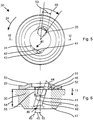
- Fig. 5 and Fig. 6 show the locking sleeve 30 in a plan view opposite to the direction of impact 11 and a cross section in the plane VI-VL.
- the inner side 31 is provided with a helical link 40 , in which the locking body 25 engage.
- the link 40 is formed for example by a groove 41 which has a leading edge 24 in the circumferential direction 42 and a trailing edge 43 .
- the two flanks 42, 43 may be cup-shaped, for example, with a circular segment-shaped cross-section perpendicular to the working axis 10 .
- the shape of the groove 41, or the groove wall, is modeled on the locking body 25 , ie a sectional figure of the groove 41 in a sectional plane perpendicular to the working axis 10 is congruent to a sectional figure of the portion of the locking body 25 which engages in the groove 41 .
- the sectional figure of the groove 41 is preferably a circular segment for spherical locking bodies 25 .
- the locking body 25 engages in the groove 41 and is in the circumferential direction 24, both clockwise and counterclockwise, inhibited by a movement in a plane perpendicular to the working axis 10 .
- the gate 40 or groove 41 winds helically around the working axis 10.
- a pitch angle 44 of the gate 40 ie the inclination of the link 40 relative to a plane perpendicular to the working axis 10 is preferably in the range between 65 degrees and 85 degrees, eg between 75 degrees and 82 degrees.
- the backdrop 40 winds preferably only by a fraction of a full revolution, for example, between 1/20 to 1/10 of a revolution, the operational axis 10.
- a in the direction of impact 11 front end 46 of the link 40 is opposite a rear in the direction of impact 11 end 47 the guide 40 is arranged rotated by an angle 48 between 5 degrees and 25 degrees about the working axis 10 , preferably viewed in the direction of impact 11 in the counterclockwise direction.
- the link 40 extends over its entire dimension along the working axis 10 in the same direction of rotation about the working axis 10, a change in the direction of rotation along the working axis 10 is not provided.
- the groove 41 may be approximately oriented as well and parallel to a longitudinal axis 49 .
- the longitudinal axis 49 is skewed to the working axis 10, ie the longitudinal axis 49 of the groove 41 is neither parallel to the working axis 10 nor does the longitudinal axis 49 intersect the working axis 10.
- Cut figures of the groove 41 perpendicular to the working axis are, although arranged in different angular positions with respect to the working axis 10 , preferably congruent.
- the locking body 25 is forcibly guided along the groove 41 .
- the locking body In a movement along the groove 41 , the locking body preferably continuously contacts the leading edge 42 and the trailing edge 43, which are at a constant distance 50 . Due to the helical or skewed flanks 42 or groove 41 , the link 40 of a locking body 25 moving along the working axis 10 forces a relative rotational movement about the working axis 10 relative to the locking sleeve 30.
- the gate 40 begins at a front edge 51 of the inner side 31 or a front end surface 52 of the locking sleeve 30.
- the locking body 25 is in its normal position ( Fig. 2 ) Is typically close to the front edge 51 and thus in engagement with the connecting link 40.
- a spring loaded washer 53 on the front end surface 52 inhibits the locking body 25 against the impact direction 11 1 of the locking sleeve 30 and thus out of engagement with the sliding exit 40th
- the annular disc 53 overlaps in the radial direction with the locking bodies 25. Due to the engagement in the basic position, the locking sleeve 30 rotates together with the receiving sleeve 20 during a drilling or drilling chisel operation of the power tool.
- a dimension 54 of the link 40 along the working axis 10 is at least 50% longer than the dimension 55 of the locking body 25 along the working axis 10 or at least 0.5 cm longer.
- the length 54 of the gate 40 is for example in the range between 0.5 cm and 2 cm.
- the gate 40 may extend over the entire length of the locking sleeve 30 .
- the tool 10 moves the working axis 4 along the extent of the tool holder 2 out until the lock body 25 abut against the rear end 28 of the elongated hole 23 ( Fig. 3 ).
- the locking body 25 thereby move in the direction of impact 11 along the working axis 10, for example, from a machine-side or front end 27 of the slots 23 to a tool-side or rear end 28 of the slots 23.
- the locking sleeve 30 due to Setting 40 forced to rotate about the working axis 10 . At least a part of the kinetic energy of the tool 4 is converted into rotational energy of the locking sleeve 30 .
- the locking sleeve 30 is rotationally accelerated in a first direction of rotation, given by the gate 40 .
- the first Direction of rotation is exemplary in the direction of impact 11 looking counterclockwise, equal to the usual direction of rotation of a drill or drill bit . 4
- the tool 4 rebounds at a rear stop, for example formed by the rear end 28 of the slots 23, and moves back against the direction of impact 11 1.
- the backward movement is not supported by the rotating locking sleeve 30 , on the contrary brakes the rotating locking sleeve 30, the tool 4.
- the reason lies in the handedness or chirality of the gate 40, which in the reverse rotation of the locking body 25 to rotate in a first direction of rotation opposite second sense of rotation is forced.
- the tool 4 quickly loses momentum and preferably remains close to the back stop.
- the rotational energy of the locking sleeve 30 can be derived by friction, for example, on the actuating sleeve 34, or by a counter torque of the user.
- the locking sleeve 30 is preferably not movable along the working axis 10 by the forces exerted by the tool 4 .
- the illustrated locking sleeve 30 is located in the direction of impact 11 against a stop.
- the springs 32 exert a force in the direction of impact 11 , which is greater than the axial portions of the transmitted from the locking bodies 25 on the link 40 forces.
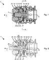
- FIGS. 7 and 8 show an embodiment of the tool holder 2, in the basic position and a blank
- Fig. 9 a cross section in the plane IX-IX
- Fig. 10 shows a section along the working axis 10 through a locking sleeve 60 of the tool holder. 2
- the locking sleeve 60 has a plurality of radially projecting to the working axis 10 ribs 62, for example between six and ten ribs 62.
- the ribs 62 are preferably uniformly distributed along the circumferential direction 24 , arranged at equal angular intervals 63 .
- Each two adjacent ribs 62 define a groove-like depression 64, which can guide the locking body 25 as a backdrop 65 .
- the angular spacing 63 is selected such that the locking body 25 preferably simultaneously contacts one of the ribs 62 leading to it in the circumferential direction 24 and one of the trailing ribs 62 in the circumferential direction 24 .
- the locking body 25 is engaged in one of the scenes 65 inhibited from moving in a plane perpendicular to the working axis 10 .
- the ribs 62 are skewed to the working axis 10 or spirally wound around the working axis 10 .
- An inclination 45 with respect to the working axis 10 is in the range between 5 degrees and 25 degrees, for example between 8 degrees and 15 degrees.
- the inclination 45 may increase in the direction of impact 11 .
- a front portion of the gate 65 may have a pitch of between 1 degree and 5 degrees, while a rear portion is inclined between 8 degrees and 15 degrees.
- the ribs 62 extend along the working axis 10 only over a first portion 66 of the inner side 61.
- a second section 67 connects with a smooth, cylindrical inner surface 68 , which is coaxial with the Working axis 10 is.
- the cylindrical inner surface 68 may abut against the locking body 25 .
- An axial dimension 69 of the cylindrical inner surface 68 is preferably about equal or up to 50% greater than a dimension 70 of the locking body 25 along the working axis 10.
- the locking sleeve 60 can rotate freely about the working axis 10 when the entire locking body 25 with the cylindrical Inner surface 68 is overlapped along the working axis 10 .
- Fig. 11 shows an embodiment of the tool holder 3 in a longitudinal section; Fig. 12 a partial section of Fig. 11 in an enlarged view.
- the tool holder 3 includes a receiving sleeve 20, which preferably has two elongated holes 23 symmetrically to the working axis 10 .
- a respective locking body 25 is inserted, which projects beyond the receiving sleeve 20 radially inward and radially outward.
- the locking sleeve 80 has a directed to the working axis 10 inside 81, which contacts the locking body 25 .
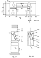
- FIG. 13 shows the locking sleeve 80 in a cross section along the plane XIII-XIII
- FIGS. 14 and 15 show the locking sleeve 80 in a longitudinal section in the same planes XIV-XIV, XV-XV in the opposite direction
- Fig. 16 schematically shows the inner side 81 against the circulation direction 24 unrolled.
- the numbers on the abscissa indicate exemplary angular positions in degrees with respect to an arbitrary zero point.
- a skewed or helical link 40 is formed, in which a first of the locking body 25 engages.
- the backdrop 40 may, for example, as above in connection with FIGS. 5 and 6 be described described.
- the gate 40 may, for example, have a skewed or helical groove 41 on the inner side 81 .
- a leading edge 24 in the circumferential direction 42 and a trailing edge 24 in the circumferential direction 43 of the groove 41 are skewed or spiral.
- a distance 50 of the two flanks 42, 43 is preferably constant along the working axis 10 . The distance 50 is chosen so that between the two flanks 42, 43 of the Latch body 25 is performed edged, that touches both the leading edge 42 and the trailing edge 43 .
- the groove 41 has a shape adapted to the locking body 25 such that the locking body 25 is enclosed in the one plane perpendicular to the working axis 10 of the groove 41 in and against the circumferential direction 24 .
- the groove 41 for example, the shape of a circular segment having a radius corresponding to a radius of the spherical locking body 25 have.
- the groove 41 begins at a front end 82 of the locking sleeve 80.
- a dimension 54 of the groove 41 along the working axis 10 is at least 50% larger than a dimension of the locking body 25 along the working axis 10.
- the locking sleeve 80 abuts the second locking body 71 in the radial direction to prevent it from disengaging from the cavity 21 .
- the second locking body 71 is not enclosed by the locking sleeve 80 in the circumferential direction 24 .
- a relative rotation about the working axis 10 of the locking sleeve 80 relative to the second locking body 71 is possible.
- the exemplary embodiment of the locking sleeve 80 has a wide recess 83 on the inner side 81.
- An edge 84 leading in the circumferential direction 24 and a trailing edge 85 in the circumferential direction 24 may be parallel to the working axis 10 .
- the angular arrangement of the recess 83 relative to the groove 41 is selected according to the angular arrangement of the locking body 25, 71, ie their slots 23 .
- the locking bodies 25, 71 are opposed by a first angle 86 equal to 180 degrees.
- the recess 83 lies opposite the groove 41 , ie, it is arranged rotated around the working axis 10 about the first angle 86 to the groove 41 .
- the locking sleeve 80 rotates when the first locking body 25 is moved along the working axis 10 .
- the wide recess 83 is formed so that its flanks 84, 85 touch the second locking body 71 in any of the assumed rotational position.
- the leading edge 84 of the recess 83 is at least the second angle 87, which is preferably greater by 10 degrees than the first angle 86 , removed. In the illustrated example of Fig. 16 the distance is 200 degrees.
- the trailing edge 85 of the recess 83 is removed from the trailing edge 43 of the groove 41 by at most a third angle 88 , which is preferably smaller by 10 degrees than the first angle, see. the example with 165 degrees away.
- the dimension 89 of the recess 83 in the circumferential direction 24 is greater than the sum of the angle 48, by which the groove 41 winds around the working axis 10 , and the dimension 50 of the groove 41 in the circumferential direction 24.
- the recess 83 is wider than a projection of the Groove 41 on a plane perpendicular to the working axis 10, preferably at least 20 degrees wider.
- a dimension 90 of the recess 83 along the working axis 10 is preferably equal to the dimension 54 of the link 40 along the working axis 10.
- the gate 40 is to be accelerated at a blank by the longitudinal axis of the working axis 10 moving locking body 25 in a rotational movement for the destruction of kinetic energy.
- the locking body 25 is also moved along the working axis 10 , but possible to put the locking sleeve 80 in rotation as possible without the expense.
- a releasable setting lock 100 inhibits or prevents in a locked position a movement of the locking sleeve 80 along the working axis 10 and allows in an unlocked position, the axial movement of the locking sleeve 80. In the latter position, the slide 40 can move in parallel with the locking body 25 and is not forced to a relative rotational movement.
- the releasable gate lock 100 is coupled to the actuating sleeve 34 .
- the gate lock 100 is unlocked.
- Actuating sleeve 34 is in a position for locking the tool 4, the gate lock 100 is also in its locked position.
- the exemplary releasable gate latch 100 includes one or more springs 32 that urge the latch sleeve 80 in the direction of impact 11 against a stop.
- the Stop forms, for example, a dust seal 101.
- the stop is rubberized to cause high friction of the locking sleeve 80 .
- the spring 32 is designed so that its spring force is greater than forces exerted by the locking sleeve 80 during operation, along the working axis 10 .
- the locking sleeve 80 has a fixed position along the working axis 10, as far as the user does not engage.
- the gate lock 100 has a rigid coupling element which is connected in the force path between the locking sleeve 80 by the spring 32 .
- the coupling element transmits the force acting in the direction of impact 11 of the spring 32 on the locking sleeve. 80 .
- the coupling member can be released from the locking sleeve 80 in order to interrupt the power path.
- the removal of the coupling element from the locking sleeve 80 is effected by the actuating sleeve, which brought by displacement or rotation in engagement with the coupling element and can take the coupling element.
- An exemplary coupling element is an annular disk 53.
- the annular disk 53 has a side facing the direction of impact 11 , against which the spring 32 rests.
- a side 115 pointing in the direction of impact 11 has two areas 116, 117.
- a first area 116 rests against the locking sleeve 80 in the basic position.
- the transmitted from the spring 32 to the annular disc 53 force is introduced in the direction of impact 11 in the locking sleeve 80 .
- a second region 117 is located in the direction of impact 11 a driver 118 of the actuating sleeve 34 opposite.
- the driver 118 may be formed, for example, by a spacer sleeve 118 which is separate from the actuating sleeve or by a projection which is positively or materially connected to the actuating sleeve 34 . Between the annular disc 53 and the driver 118 is in the normal position preferably a small air gap 119 to ensure that the force of the spring 32 is introduced into the locking sleeve 80 and not into the actuating sleeve 34 . When a user moves the actuating sleeve 34 against the direction of impact 11 , for example when removing the tool 4, the driver 118 moves the annular disc 53 against the direction of impact 11.
- the force of the spring 32 is now introduced through the annular disc 53 in the actuating sleeve 34 , the locking sleeve 80 is powerless. A braking action of the locking sleeve 80 is reduced or canceled.
- the actuating sleeve 34 and the locking sleeve 80 are preferably only weakly coupled along the working axis 10 , in particular compared to the force of the spring 32nd
- the actuating sleeve 34 may be an alternative or additional coupling element of the gate lock 100 .
- An example annular, radial projection 102 of the actuating sleeve 34 engages behind a radial projection 103 of the locking sleeve 80 on a side facing the spring 32.
- a surface 104 of the actuating sleeve 34 pointing in the direction of impact 11 bears against a surface 105 of the locking sleeve 80 facing the direction of impact 11 ,
- the spring force of the spring 32 is transmitted through the actuating sleeve 34 on the locking sleeve 80 .
- the force flow is interrupted and the locking sleeve 80 is decoupled from the springs 32 .
- the actuating sleeve 34 and the locking sleeve 80 may be coupled by a soft spring 106 of the gate latch 100 .
- the soft spring 106 counteracts a relative displacement of the actuating sleeve 34 in the direction of impact 11 relative to the locking sleeve 80 .
- the soft spring 106 is preferably a compression spring disposed in a force path along the working axis 10 between the actuating sleeve 34 and the locking sleeve 80 . In the basic position of the tool holder 3, the soft spring is preferably relaxed.
- the soft spring 106 is arranged between a stop 109 pointing in the direction of impact 11 of the locking sleeve 80 and a counter to the direction of impact 11 facing stop 108 of the actuating sleeve 34 .
- the two stops 108, 109 are, for example, rings which are immovable axially relative to the actuating sleeve 34 or locking sleeve 80 but are rotatable relative to the actuating sleeve 34 and locking sleeve 80 about the working axis 10 .
- the ring 109 may be, for example, a snap ring inserted into an annular groove in the lock sleeve 80 .
- an air gap 107 may be between the soft spring 106 and one of the stoppers 108, 109 as long as the actuating sleeve 34 is in the home position.
- the spring constant of the soft spring 106 is preferably less than one-fifth of the spring force of the springs 32.
- the soft spring 32 may be a coil spring or a ring made of an elastomer.
- the locking sleeve 80 moves when changing, in particular removal, the tool 4 along the working axis 10 and is forced to a lesser extent in a rotary motion.
- the soft spring 106 causes entrainment of the locking sleeve 80 when a user moves the actuating sleeve 34 against the direction of impact 11 .
- the free space 33 shifts in the direction of the slot 23, in which the locking body 25 can escape radially to release the shaft 3 .
- the gate lock 100 is described only by way of example in connection with the locking sleeve 80 and can also be used in the other embodiments of the tool holder 2 .
- Fig. 17 shows a receiving sleeve 110 of a further embodiment of the tool holder 2, Fig. 18 a partial section along the working axis 10.
- the receiving sleeve 110 has one or more slots 111, are inserted into the locking body 25 .
- the locking body 25 protrude into the prismatic or cylindrical cavity 21 of the receiving sleeve 110 to lock an inserted tool 4 with a locking groove.
- the locking body 25 has a smaller dimension along the working axis 10 than the slot 111 and can therefore move along the working axis 10 in the slot 111 .
- the elongated hole 111 represents a link 120 for the locking body 25 .
- At least a portion of the slot 111 is helically wound around the working axis 10 .
- An in the direction of impact 11 rear end 121 of the slot 111 is disposed opposite to a front end in the direction of impact 11 122 rotated about the working axis 10 .
- the slot 111 is rotated in the direction of impact 11 viewed counterclockwise.
- the tool holder 2 has short or no webs 22 for a rotational drive, to allow rotation of the tool 4 about the working axis 10 .
- a dimension of the webs 22 along the working axis 10 is dimensioned such that the shaft end 3 from the engagement of the webs 22 , when the tool 4 starts to move the locking body 25 along the working axis 10 .
- the web 22 may, for example, along the working axis 10 offset from the slots 123 may be arranged.
- both the slot 111 with a helical link 120, as well as on the inside 31 of the locking sleeve 80 have a helical link 40 .
Landscapes
- Engineering & Computer Science (AREA)
- Mechanical Engineering (AREA)
- Percussive Tools And Related Accessories (AREA)
Abstract
Description
- Die vorliegende Erfindung betrifft eine Werkzeugaufnahme, insbesondere für eine meißelnde, rein meißelnde und/oder bohrmeißelnde Werkzeugmaschine.
- Ein Bohrhammer oder eine andere meißelnde Werkzeugmaschine soll ihren Betrieb selbst einstellen, sobald ein Anwender den Bohrhammer samt dem meißelnden Werkzeug von einem Untergrund oder Werkstück abhebt. Hierdurch wird eine Belastung des Anwenders und des Bohrhammers verringert. Das Abschalten wird ausgelöst, wenn das Werkzeug typisch für das Abheben von dem Bohrhammer weg aus einer Werkzeugaufnahme maximal ausrückt. Allerdings kann das Werkzeug aufgrund des zuletzt erhaltenen Schlags an einem Anschlag abprallen und in die Werkzeugaufnahme wieder einrücken. Ein Dämpfung dieses sogenannten Leerschlags kann ein solches Rückprallen verhindern und ein automatisches Abschalten begünstigen.
- Die erfindungsgemäße Werkzeugaufnahme für eine meißelnde Werkzeugmaschine hat eine zu einer Arbeitsachse konzentrisch angeordneten Aufnahmehülse zum Aufnehmen eines Schaftendes eines Werkzeugs mit einer oder mehreren Verriegelungsnuten. Ein Verriegelungskörper der Werkzeugaufnahme ragt teilweise in die Aufnahmehülse zum Eingreifen in die Verriegelungsnut hinein. Der Verriegelungskörper ist längs der Arbeitsachse beweglich. Eine Kulisse ist mit dem Verriegelungskörper derart gekoppelt dass die Kulisse den Verriegelungskörper mittelbar oder unmittelbar führt. Die Kulisse hat einen um die Arbeitsachse schraubenförmig gewunden oder zur Arbeitsachse windschiefen Abschnitt. Die translatorische Bewegung des Werkzeugs bei einem Leerschlag führt zu einer Mitnahme des Verriegelungskörpers längs der Arbeitsachse. Die Kulisse erzwingt eine relative Rotation wenigstens eines Bauteils der Werkzeugmaschine gegenüber dem Werkzeug, wodurch wenigstens ein Teil der Stoßenergie in Rotationsenergie umgewandelt wird. Die Chiralität der Kulisse verhindert, dass die Rotationsenergie für eine Rückwärtsbewegung des Werkzeugs in die Werkzeugmaschine zurückgewonnen werden kann. Das Werkzeug bleibt vorzugsweise ausgerückt stehen. Die axial beweglichen Verriegelungskörper können selbst durch die Kulisse zu einer Rotation gezwungen sein und/oder die Kulisse in Rotation versetzten, falls die Kulisse gegenüber dem Verriegelungskörper um die Arbeitsachse drehbar gelagert ist. Weiters kann das Bauteil die Kulisse statt einer Drehung um die Arbeitsachse translatorisch senkrecht zur Arbeitsachse verschoben werden.
- Eine Ausgestaltung sieht vor, dass eine Verriegelungshülse mit einer radial zur Arbeitsachse weisenden Innenseite den wenigstens einen Verriegelungskörper berührt und die Kulisse an der Innenseite der Verriegelungshülse ausgebildet ist. Die Verriegelungshülse hat ein großes Trägheitsmoment, welches die Umwandlung eines großen Anteils der Stoßenergie in Rotationsenergie ermöglicht. Die Verriegelungshülse kann um die Arbeitsachse drehbar gelagert sein.
- Eine Ausgestaltung sieht vor, dass die Verriegelungshülse eine Aussparung an der Innenseite aufweist, in die ein weiterer Verriegelungskörper hineinragt, wobei eine Abmessung der Aussparung in Umfangsrichtung größer als eine Abmessung der Kulisse in Umfangsrichtung ist. Die Aussparung kann zur Arbeitsachse parallele Flanken aufweisen und die Kulisse kann zur Arbeitsachse windschiefe oder um die Arbeitsachse gewundene Flanken aufweisen. Bei einer Werkzeugaufnahme mit mehr als einem Verriegelungskörper zum Verriegeln des Werkzeugs kann es vorteilhaft sein, nur einen der Verriegelungskörper in einer schraubenförmigen oder windschiefen Kulisse zwangszuführen. Der oder die anderen Verriegelungskörper können unbeeinflusst von der Kulisse und einer Drehbewegung der Kulisse in ein oder mehreren der Aussparungen entlang der Arbeitsachse innerhalb der Verriegelungshülse bewegt werden.
- Eine Ausgestaltung hat eine lösbare Kulissenverriegelung, die in einer verriegelnden Stellung die Kulisse in Schlagrichtung mit einer Feder kraftbeaufschlagt und in einer entriegelten Stellung die Feder von der Kulisse entkoppelt. Die Verriegelungshülse wird längs der Arbeitsachse beweglich, wodurch Reibungskräfte, die gegen eine Drehung wirken, verringert werden können. Weiters reduziert sich die Drehbewegung der Verriegelungshülse, da sie sich synchron zu den Verriegelungskörpern axial bewegen kann. Die Kulissenverriegelung kann die Feder und ein Kupplungselement aufweisen. Das Kupplungselement liegt durch die Feder kraftbeaufschlagt in Schlagrichtung an der Verriegelungshülse an. Ein von dem Anwender betätigbare Betätigungshülse der Werkzeugaufnahme ist entgegen der Schlagrichtung relativ zu der Verriegelungshülse beweglich. Die Betätigungshülse kann ferner mit dem Kupplungselement verbunden sein, z.B. materialschlüssig oder formschlüssig. Alternativ oder zusätzlich kann die Betätigungshülse entgegen der Schlagrichtung an dem Kupplungselement unmittelbar oder mittelbar durch eine starre Verbindung abgestützt sein.
- Die nachfolgende Beschreibung erläutert die Erfindung anhand von exemplarischen Ausführungsformen und Figuren. In den Figuren zeigen:
-
Fig. 1 eine Handwerkzeugmaschine, -
Fig. 2 bis 4 eine Werkzeugaufnahme, -
Fig. 5 und 6 eine Verriegelungshülse der Werkzeugaufnahme, -
Fig. 7 bis 9 eine Werkzeugaufnahme, -
Fig. 10 eine Verriegelungshülse der Werkzeugaufnahme" -
Fig. 11 und Fig. 12 eine Werkzeugaufnahme, -
Fig. 13 bis Fig. 15 eine Verriegelungshülse der Werkzeugaufnahme, -
Fig. 16 eine abgerollte der Darstellung der Verriegelungshülse, -
Fig. 17 und Fig. 18 eine Aufnahmehülse einer Werkzeugaufnahme. - Gleiche oder funktionsgleiche Elemente werden durch gleiche Bezugszeichen in den Figuren indiziert, soweit nicht anders angegeben. Radial und axiale Richtungen beziehen sich, soweit es nicht explizit anders angegeben, auf eine Arbeitsachse der Werkzeugmaschine. Orientierungen sind ohne weiteren Vermerk in Bezug auf eine Schlagrichtung der Werkzeugmaschine angegeben, wonach ein hinteres Element gegenüber einem vorderen Element in Schlagrichtung versetzt ist. Eine Länge bezeichnet eine Abmessung längs einer (Längs-) Richtung der größten Ausdehnung eines Körpers, eine Breite ist die größte Abmessung in der Ebene senkrecht zu der Längsrichtung.
-
Fig. 1 zeigt als Beispiel einer meißelnden Handwerkzeugmaschine schematisch einen Bohrhammer 1. Der Bohrhammer 1 hat eine Werkzeugaufnahme 2, in welche ein Schaftende 3 eines Werkzeug, z.B. eines des Bohrmeißels 4, eingesetzt werden kann. Einen primären Antrieb des Bohrhammers 1 bildet ein Motor 5, welcher ein Schlagwerk 6 und eine Abtriebswelle 7 antreibt. Ein Anwender kann den Bohrhammer 1 mittels eines Handgriffs 8 führen und mittels eines Systemschalters 9 den Bohrhammer 1 in Betrieb nehmen. Im Betrieb dreht der Bohrhammer 1 den Bohrmeißel 4 kontinuierlich um eine Arbeitsachse 10 und kann dabei den Bohrmeißel 4 in Schlagrichtung 11 längs der Arbeitsachse 10 in einen Untergrund schlagen. - Das Schlagwerk 6 ist beispielsweise ein pneumatisches Schlagwerk 6. Ein Erreger 12 und ein Schläger 13 sind in dem Schlagwerk 6 längs der Arbeitsachse 10 beweglich geführt. Der Erreger 12 ist über einen Exzenter 14 oder einen Taumelfinger an den Motor 5 angekoppelt und zu einer periodischen, linearen Bewegung gezwungen. Eine Luftfeder gebildet durch eine pneumatische Kammer 15 zwischen Erreger 12 und Schläger 13 koppelt eine Bewegung des Schlägers 13 an die Bewegung des Erregers 12 an. Der Schläger 13 kann direkt auf ein hinteres Ende des Bohrmeißels 4 aufschlagen oder mittelbar über einen im Wesentlichen ruhenden Zwischenschläger 16 einen Teil seines Impuls auf den Bohrmeißel 4 übertragen. Das Schlagwerk 6 und vorzugsweise die weiteren Antriebskomponenten sind innerhalb eines Maschinengehäuses 17 angeordnet.
-
Fig. 2 und Fig. 3 zeigen Details der Werkzeugaufnahme 2 mit einem beispielhaften eingesetzten Schaftende 3, welches inFig. 2 in einer Grundstellung für einen bohrmeißelnden Betrieb, also anliegend an dem Zwischenschläger 16, und inFig. 3 in einer Stellung bei einem Leerschlag dargestellt ist.Fig. 4 zeigt einen Querschnitt in der Ebene IV-IV. Die Werkzeugaufnahme 2 hat eine Aufnahmehülse 20, die konzentrisch zu der Arbeitsachse 10 angeordnet ist. Ein Innendurchmesser eines zylindrischen oder prismatischen Hohlraums 21 der Aufnahmehülse 20 ist mit einem geringen Spiel nahezu gleich einem Außendurchmesser des Schaftendes 3, welches weitgehend standardisiert ist. Das Schaftende 3 ist in der Aufnahmehülse 20 längs der Arbeitsachse 10 geführt. Die dargestellte Werkzeugaufnahme 2 weist Stege 22 für eine Drehmitnahme des Schaftendes 3 auf. Die Stege 22 sind starr mit der Aufnahmehülse 20 verbunden und ragen in den Hohlraum 21 hinein. Geeignete Werkzeuge, z.B. Bohrmeißel, haben an ihrem Schaftende offene Längsnuten, in die die Stege 22 eingreifen. Das Schaftende 3 ist folglich gegen eine relative Drehung gegenüber der Aufnahmehülse 20 gesperrt und ein auf die Aufnahmehülse 20 ausgeübtes Drehmoment des Antriebs überträgt sich auf das Werkzeug 4. - Die Aufnahmehülse 20 ist durch zwei Langlöcher 23 durchbrochen, welche den Hohlraum 21 in radialer Richtung, d.h. senkrecht zur Arbeitsachse 10 öffnen. Eine Abmessung der Langlöcher 23 längs der Arbeitsachse 10 ist typisch geringer als eine Abmessung der Langlöcher 23 in Umfangsrichtung 24 um die Arbeitsachse 10. Verriegelungskörper 25 sind in die Langlöcher 23 eingesetzt und längs der Arbeitsachse 10 beweglich. Längsseiten 26 der Langlöcher 23 führen die Verriegelungskörper 25 in den Langlöchern 23 längs der Arbeitsachse 10 zwischen einem vorderen Ende 27 und einem hinteren Ende 28. Beispiele für die Verriegelungskörper 25 sind rollende Kugeln, rollende Walzen, Klinken oder gleitende Stifte. Eine radiale Abmessung der Langlöcher 26 ist geringer als eine radiale Abmessung der Verriegelungskörper 25. Die Verriegelungskörper 25 ragen sowohl nach Außen, d.h. von der Arbeitsachse 10 weg, über die Aufnahmehülse 20 hinaus, als auch nach Innen in den Hohlraum 21 der Aufnahmehülse 20 hinein.
- Das Schaftende 3 hat längs der Arbeitsachse 10 eine oder mehrere beidseitig geschlossene Verriegelungsnuten 29, in welche die Verriegelungskörper 25 eingreifen. Bei dem dargestellten Schaftende 3 ist eine Längsnut als Verriegelungsnut 29 vorgesehen. Das Werkzeug 4 ist in der Grundstellung maximal in die Werkzeugaufnahme 2 eingerückt, wobei die Verriegelungskörper 25 an dem vorderen Ende 27 der Langlöcher 23 anliegen können. Bei einem Leerschlag des Werkzeugs 4 kann das Werkzeug 4 sich in der Werkzeugaufnahme 2 längs der Arbeitsachse 10 um eine erste Wegstrecke bewegen, ohne die Verriegelungskörper 25 mitzunehmen, und anschließend um eine zweite Wegstrecke bewegen, wobei dann die Verriegelungskörper 25 entlang der Langlöcher 23 verschoben werden, bis die Verriegelungskörper 25 an dem hinteren Ende 28 zum Anliegen kommen. Alternative Schaftenden können beispielsweise eine kreisförmige Nut oder eine Ringnut aufweisen, in welchem Fall bei einer axialen Bewegung des Werkzeugs 4 immer die Verriegelungskörper 25 bewegt werden.
- Eine Verriegelungshülse 30 ist über die Aufnahmehülse 20 und die Verriegelungskörper 25 gestülpt. Eine radial nach innen weisende Innenseite 31 der Verriegelungshülse 30 liegt an den Verriegelungskörpern 25 an, wodurch diese an einem Ausrücken aus dem Hohlraum 21 gehindert sind. Ein eingesetztes Werkzeug 4 ist somit mittels der Verriegelungskörper 25 und der Verriegelungshülse 30 verriegelt. Die Verriegelungshülse 30 kann gegen eine Rückstellkraft einer oder mehrerer Federn 32 axial verschoben werden, wodurch angrenzend an die Verriegelungskörper 25 in radialer Richtung ein Freiraum 33 freigegeben wird, in welchen die Verriegelungskörper 25 zum Ausrücken aus dem Hohlraum 21 ausweichen können. Ein Anwender kann die Verriegelungshülse 30 mittelbar durch eine von Außen frei zugängliche Betätigungshülse 34 verschieben. Die Verriegelungshülse 30 ist um die Arbeitsachse 10 drehbar gelagert. Insbesondere kann sich die Verriegelungshülse 30 um die Aufnahmehülse 20 drehen. Vorzugsweise kann sich die Verriegelungshülse 30 in der Betätigungshülse 34 ohne diese mitzunehmen frei drehen.
-
Fig. 5 und Fig. 6 zeigen die Verriegelungshülse 30 in einer Draufsicht entgegen der Schlagrichtung 11 und einem Querschnitt in der Ebene VI-VL. Die Innenseite 31 ist mit einer schraubenförmigen Kulisse 40 versehen, in die die Verriegelungskörper 25 eingreifen. Die Kulisse 40 ist beispielsweise durch eine Nut 41 ausgebildet, welche eine in Umfangsrichtung 24 vorlaufende Flanke 42 und eine nachlaufende Flanke 43 hat. Die beiden Flanken 42, 43 können schalenförmig, z.B. mit einem kreissegmentförmigen Querschnitt senkrecht zur Arbeitsachse 10 sein. Die Form der Nut 41, bzw. die Nutwand, ist dem Verriegelungskörper 25 nachgebildet, d.h. eine Schnittfigur der Nut 41 in einer Schnittebene senkrecht zur Arbeitsachse 10 ist deckungsgleich zu einer Schnittfigur des Anteils des Verriegelungskörpers 25, welcher in die Nut 41 eingreift. Die Schnittfigur der Nut 41 ist vorzugsweise für kugelförmige Verriegelungskörper 25 ein Kreissegment. Der Verriegelungskörper 25 greift in die Nut 41 ein und ist in Umfangsrichtung 24, sowohl im Uhrzeigersinn als auch gegen den Uhrzeigersinn, an einer Bewegung in einer Ebene senkrecht zur Arbeitsachse 10 gehemmt. - Die Kulisse 40 oder Nut 41 windet sich schraubenförmig um die Arbeitsachse 10. Ein Gangwinkel 44 der Kulisse 40, d.h. die Neigung der Kulisse 40 gegenüber einer Ebene senkrecht zur Arbeitsachse 10 liegt vorzugsweise im Bereich zwischen 65 Grad und 85 Grad, z.B. zwischen 75 Grad und 82 Grad. Ein Steigungswinkel 45 der Nut 41 gegenüber der Arbeitsachse 10, bestimmt entlang einer Zylinderfläche um die Arbeitsachse 10, liegt entsprechend vorzugsweise im Bereich zwischen 5 Grad und 25 Grad, z.B. zwischen 8 Grad und 15 Grad. Die Kulisse 40 windet sich vorzugsweise nur um einen Bruchteil eines vollen Umlaufs, z.B. zwischen 1/20 bis 1/10 eines Umlaufs, um die Arbeitsachse 10. Ein in Schlagrichtung 11 vorderes Ende 46 der Kulisse 40 ist gegenüber einem in Schlagrichtung 11 hinteren Ende 47 der Kulisse 40 um einen Winkel 48 zwischen 5 Grad und 25 Grad um die Arbeitsachse 10 gedreht angeordnet, vorzugsweise entgegen dem Uhrzeigersinn in Schlagrichtung 11 betrachtet. Die Kulisse 40 verläuft über seine gesamte Abmessung längs der Arbeitsachse 10 in gleichem Drehsinn um die Arbeitsachse 10, ein Wechsel des Drehsinns längs der Arbeitsachse 10 ist nicht vorgesehen. Die Nut 41 kann näherungsweise auch als gerade und parallel zu einer Längsachse 49 orientiert sein. Die Längsachse 49 ist windschief zu der Arbeitsachse 10, d.h. die Längsachse 49 der Nut 41 ist weder parallel zu der Arbeitsachse 10 noch schneidet die Längsachse 49 die Arbeitsachse 10.
- Schnittfiguren der Nut 41 senkrecht zur Arbeitsachse sind, wenn auch in verschiedenen Winkelpositionen bezogen auf die Arbeitsachse 10 angeordnet, vorzugsweise deckungsgleich. Der Verriegelungskörper 25 ist entlang der Nut 41 fortwährend zwangsgeführt. Bei einer Bewegung entlang der Nut 41 berührt der Verriegelungskörper vorzugsweise fortwährend die vorlaufende Flanke 42 und die nachlaufende Flanke 43, die in konstanten Abstand 50 sind. Aufgrund der schraubenförmigen oder windschiefen Flanken 42 bzw. Nut 41 zwingt die Kulisse 40 einer sich längs der Arbeitsachse 10 bewegenden Verriegelungskörper 25 zu einer relativen Drehbewegung um die Arbeitsachse 10 bezogen auf die Verriegelungshülse 30.
- In der dargestellten Ausführungsform beginnt die Kulisse 40 an einer vorderen Kante 51 der Innenseite 31 oder einer vorderen Stirnfläche 52 der Verriegelungshülse 30. Der Verriegelungskörper 25 ist in seiner Grundstellung (
Fig. 2 ) typischerweise nahe der vorderen Kante 51 und somit im Eingriff mit der Kulisse 40. Eine federbelastete Ringscheibe 53 an der vorderen Stirnfläche 52 hemmt den Verriegelungskörper 25 entgegen der Schlagrichtung 11 1 aus der Verriegelungshülse 30 und somit aus dem Eingriff mit der Kulisse 40 auszutreten. Die Ringscheibe 53 überlappt in radialer Richtung mit den Verriegelungskörpern 25. Aufgrund des Eingriffs in der Grundstellung dreht sich die Verriegelungshülse 30 zusammen mit der Aufnahmehülse 20 während eines bohrenden oder bohrmeißelnden Betriebs der Handwerkzeugmaschine. - Eine Abmessung 54 der Kulisse 40 längs der Arbeitsachse 10 ist wenigstens 50 % länger wie die Abmessung 55 des Verriegelungskörpers 25 längs der Arbeitsachse 10 oder um wenigstens 0,5 cm länger. Die Länge 54 der Kulisse 40 liegt beispielsweise im Bereich zwischen 0,5 cm und 2 cm. Die Kulisse 40 kann sich über die gesamte Länge der Verriegelungshülse 30 erstrecken.
- Bei einem Leerschlag des Werkzeugs 4 bewegt sich das Werkzeug 4 längs der Arbeitsachse 10 soweit aus der Werkzeugaufnahme 2 heraus, bis die Verriegelungskörper 25 an dem hinteren Ende 28 des Langlochs 23 anschlagen (
Fig. 3 ). Die Verriegelungskörper 25 bewegen sich dabei in Schlagrichtung 11 entlang der Arbeitsachse 10, z.B. von einem maschinenseitigen oder vorderen Ende 27 der Langlöcher 23 zu einem werkzeugseitigen oder hinterem Ende 28 der Langlöcher 23. Der axialen Bewegung der Verriegelungskörper 25 folgend, wird die Verriegelungshülse 30 aufgrund der Kulisse 40 zu einer Drehung um die Arbeitsachse 10 gezwungen. Wenigstens ein Teil der Bewegungsenergie des Werkzeugs 4 wird in Rotationsenergie der Verriegelungshülse 30 umgewandelt. Die Verriegelungshülse 30 wird in einem ersten Drehsinn, vorgegeben durch die Kulisse 40, drehbeschleunigt. Der erste Drehsinn ist beispielhaft in Schlagrichtung 11 blickend gegen den Uhrzeigersinn, gleich dem üblichen Drehsinn eines Bohrers oder Bohrmeißels 4. - Typischerweise prallt das Werkzeug 4 an einem hinteren Anschlag ab, z.B. gebildet durch das hintere Ende 28 der Langlöcher 23, und bewegt sich entgegen der Schlagrichtung 11 1 zurück. Die Rückwärtsbewegung ist durch die sich drehende Verriegelungshülse 30 nicht unterstützt, im Gegenteil bremst die drehende Verriegelungshülse 30 das Werkzeug 4. Der Grund liegt in der Händigkeit oder Chiralität der Kulisse 40, welche bei der Rückwärtsbewegung der Verriegelungskörper 25 zum Drehen in einem dem ersten Drehsinn entgegengesetzten zweiten Drehsinn gezwungen ist. Das Werkzeug 4 verliert rasch an Bewegungsenergie und bleibt vorzugsweise nahe dem hinteren Anschlag liegen. Die Rotationsenergie der Verriegelungshülse 30 kann durch Reibung z.B. an der Betätigungshülse 34, oder durch ein Gegendrehmoment des Anwenders abgeleitet werden.
- Die Verriegelungshülse 30 ist vorzugsweise längs der Arbeitsachse 10 durch die von dem Werkzeug 4 ausgeübten Kräften nicht bewegbar. Die dargestellte Verriegelungshülse 30 liegt in Schlagrichtung 11 an einem Anschlag an. Die Federn 32 üben eine Kraft in Schlagrichtung 11 aus, die größer als die axialen Anteile der von den Verriegelungskörpern 25 auf die Kulisse 40 übertragenen Kräfte ist.
-
Fig. 7 und Fig. 8 zeigen eine Ausführungsform der Werkzeugaufnahme 2, in Grundstellung und bei einem Leerschlag,Fig. 9 einen Querschnitt in der Ebene IX-IX.Fig. 10 zeigt einen Schnitt längs der Arbeitsachse 10 durch eine Verriegelungshülse 60 der Werkzeugaufnahme 2. - An einer der Arbeitsachse 10 zugewandten Innenseite 61 hat die Verriegelungshülse 60 mehrere radial zur Arbeitsachse 10 vorstehende Rippen 62, z.B. zwischen sechs und zehn Rippen 62. Die Rippen 62 sind vorzugsweise entlang der Umfangsrichtung 24 gleichverteilt, in gleichen Winkelabständen 63 angeordnet. Jeweils zwei benachbarte Rippen 62 begrenzen eine nutähnliche Vertiefung 64, welche als Kulisse 65 die Verriegelungskörper 25 führen kann. Der Winkelabstand 63 ist derart gewählt, dass der Verrieglungskörper 25 vorzugsweise gleichzeitig eine der ihm in Umfangsrichtung 24 vorlaufende und eine der ihm in Umfangsrichtung 24 nachlaufende Rippen 62 berührt. Der Verriegelungskörper 25 ist eingreifend in eine der Kulissen 65 an einer Bewegung in einer Ebene senkrecht zu der Arbeitsachse 10 gehemmt. Die Rippen 62 sind zu der Arbeitsachse 10 windschief oder um die Arbeitsachse 10 spiralförmig gewunden. Eine Neigung 45 gegenüber der Arbeitsachse 10 liegt im Bereich zwischen 5 Grad und 25 Grad, z.B. zwischen 8 Grad und 15 Grad.
- Die Neigung 45 kann in Schlagrichtung 11 zunehmen. Insbesondere kann ein vorderer Abschnitt der Kulisse 65 eine Steigung von zwischen 1 Grad und 5 Grad aufweisen, während ein hinterer Abschnitt zwischen 8 Grad und 15 Grad geneigt ist.
- Die Rippen 62 erstrecken sich längs der Arbeitsachse 10 nur über einen ersten Abschnitt 66 der Innenseite 61. An die Rippen 62 bzw. Kulissen 65 schließt sich entgegen der Schlagrichtung 11 ein zweiter Abschnitt 67 mit einer glatten, zylindrischen Innenfläche 68 an, die koaxial zu der Arbeitsachse 10 ist. Die zylindrische Innenfläche 68 kann an dem Verriegelungskörper 25 anliegen. Eine axiale Abmessung 69 der zylindrischen Innenfläche 68 ist vorzugsweise etwa gleich oder bis zu 50% größer als eine Abmessung 70 des Verriegelungskörpers 25 längs der Arbeitsachse 10. Die Verriegelungshülse 60 kann sich frei um die Arbeitsachse 10 drehen, wenn der gesamte Verriegelungskörper 25 mit der zylindrischen Innenfläche 68 längs der Arbeitsachse 10 überlappt.
-
Fig. 11 zeigt eine Ausführungsform der Werkzeugaufnahme 3 in einem Längsschnitt;Fig. 12 einen Teilausschnitt vonFig. 11 in vergrößerter Darstellung. Die Werkzeugaufnahme 3 beinhaltet eine Aufnahmehülse 20, die vorzugsweise symmetrisch zur Arbeitsachse 10 zwei Langlöcher 23 aufweist. In die Langlöcher 23 ist jeweils ein Verriegelungskörper 25, 71 eingesetzt ist, welcher die Aufnahmehülse 20 radial nach Innen und radial nach Außen überragt. Die Verriegelungshülse 80 hat eine zur Arbeitsachse 10 gerichtete Innenseite 81, die die Verriegelungskörper 25 berührt. -
Fig. 13 zeigt die Verriegelungshülse 80 in einem Querschnitt entlang der Ebene Xlll-XIII,Fig. 14 und Fig. 15 zeigen die Verriegelungshülse 80 in einem Längsschnitt in den gleichen Ebenen XIV-XIV, XV-XV in entgegengesetzte Blickrichtung.Fig. 16 zeigt schematisiert die Innenseite 81 entgegen der Umlaufsrichtung 24 abgerollt. Die Zahlen an der Abszisse geben beispielhafte Winkelpositionen in Grad bezüglich eines willkürlich gewählten Nullpunkts an. - An der Innenseite 81 ist eine windschiefe oder schraubenförmige Kulisse 40 ausgebildet, in welche ein erster der Verriegelungskörper 25 eingreift. Die Kulisse 40 kann beispielsweise wie obig in Zusammenhang mit
Fig. 5 und 6 beschrieben ausgebildet sein. Die Kulisse 40 kann beispielsweise eine windschiefe oder schraubenförmige Nut 41 an der Innenseite 81 aufweisen. Eine in Umfangsrichtung 24 vorlaufende Flanke 42 und eine in Umfangsrichtung 24 nachlaufende Flanke 43 der Nut 41 sind windschief oder spiralförmig. Ein Abstand 50 der beiden Flanken 42, 43 ist vorzugsweise längs der Arbeitsachse 10 gleichbleibend. Der Abstand 50 ist so gewählt, dass zwischen den beiden Flanken 42, 43 der Verriegelungskörper 25 eingefasst geführt ist, d.h. sowohl die vorlaufende Flanke 42 als auch die nachlaufende Flanke 43 berührt. - Die Nut 41 hat eine dem Verriegelungskörper 25 derart angepasste Form, dass der Verriegelungskörper 25 in der einer Ebene senkrecht zur Arbeitsachse 10 von der Nut 41 in und gegen die Umfangsrichtung 24 einfasst ist. In einem Querschnitt senkrecht zur Arbeitsachse 10 kann die Nut 41 beispielsweise die Form eines Kreissegments mit einem Radius, der einem Radius des kugelförmigen Verriegelungskörpers 25 entspricht, aufweisen. In einer bevorzugten Ausführungsform beginnt die Nut 41 an einem vorderen Ende 82 der Verriegelungshülse 80. Eine Abmessung 54 der Nut 41 längs der Arbeitsachse 10 ist um wenigstens 50 % größer als eine Abmessung des Verriegelungskörpers 25 längs der Arbeitsachse 10.
- Die Verriegelungshülse 80 liegt an dem zweiten Verriegelungskörper 71 in radialer Richtung an, um diesen am Ausrücken aus dem Hohlraum 21 zu hindern. Im Gegensatz zu dem ersten Verriegelungskörper 25 ist der zweite Verriegelungskörper 71 in Umfangsrichtung 24 nicht von der Verriegelungshülse 80 eingefasst. Eine relative Drehung um die Arbeitsachse 10 der Verriegelungshülse 80 gegenüber dem zweiten Verriegelungskörper 71 ist möglich.
- Die beispielhafte Ausführungsform der Verriegelungshülse 80 hat eine breite Aussparung 83 an der Innenseite 81. Eine in Umfangsrichtung 24 vorlaufende Flanke 84 und eine in Umfangsrichtung 24 nachlaufende Flanke 85 können parallel zu der Arbeitsachse 10 sein. Die Winkelanordnung der Aussparung 83 gegenüber der Nut 41 ist entsprechend der Winkelanordnung der Verriegelungskörper 25, 71, d.h. deren Langlöcher 23 gewählt. Bei dem Beispiel sind die Verriegelungskörper 25, 71 gegenüberliegend, um einen ersten Winkel 86 gleich 180 Grad angeordnet. Die Aussparung 83 liegt der Nut 41 gegenüber, d.h. ist um den ersten Winkel 86 zu der Nut 41 um die Arbeitsachse 10 gedreht angeordnet.
- Wie vorausgehend beschrieben dreht sich die Verriegelungshülse 80, wenn der erste Verriegelungskörper 25 längs der Arbeitsachse 10 bewegt wird. Die breite Aussparung 83 ist so ausgebildet, dass deren Flanken 84, 85 den zweiten Verriegelungskörper 71 in keiner der eingenommenen Drehstellung berühren. Die vorlaufende Flanke 84 der Aussparung 83 ist um wenigstens den zweiten Winkel 87, der vorzugsweise um 10 Grad größer als der erste Winkel 86 ist, entfernt. In dem dargestellten Beispiel von
Fig. 16 ist der Abstand 200 Grad. Die nachlaufende Flanke 85 der Aussparung 83 ist von der nachlaufenden Flanke 43 der Nut 41 um höchstens einen dritten Winkel 88 entfernt, welcher vorzugsweise um 10 Grad kleiner als der erste Winkel ist, vgl. das Beispiel mit 165 Grad entfernt. - Die Abmessung 89 der Aussparung 83 in Umfangsrichtung 24 ist größer als die Summe des Winkels 48, um den die Nut 41 sich um die Arbeitsachse 10 windet, und die Abmessung 50 der Nut 41 in Umfangsrichtung 24. Die Aussparung 83 ist breiter als eine Projektion der Nut 41 auf eine Ebene senkrecht zur Arbeitsachse 10, vorzugsweise um wenigstens 20 Grad breiter.
- Eine Abmessung 90 der Aussparung 83 längs der Arbeitsachse 10 ist vorzugsweise gleich der Abmessung 54 der Kulisse 40 längs der Arbeitsachse 10. Bei einer durch einen Leerschlag ausgelösten gemeinsamen geradlinigen Bewegung des ersten Verriegelungskörpers 25 und des zweiten Verriegelungskörpers 25 längs der Arbeitsachse 10 zwingt der erste Verriegelungskörper 25 die Verriegelungshülse 80 zu einer Rotation, während der zweite Verriegelungskörper 25 keine Kraft in oder gegen die Umfangsrichtung 24 auf die Verriegelungshülse 80 ausübt. Die Aussparung 83 hat ausreichend Spiel in Umfangsrichtung 24, so dass deren Kanten oder Flanken 84, 85 von dem zweiten Verriegelungskörper 25 bei der sich drehenden Verriegelungshülse 80 beabstandet bleiben.
- Die Kulisse 40 soll bei einem Leerschlag durch den längs der Arbeitsachse 10 bewegten Verriegelungskörper 25 in eine Drehbewegung zum Vernichten von Bewegungsenergie beschleunigt werden. Beim Einsetzen oder Entnehmen eines Werkzeugs 4 wird das Verriegelungskörper 25 ebenfalls längs der Arbeitsachse 10 bewegt, jedoch möglichst ohne den Aufwand die Verriegelungshülse 80 in eine Drehung zu versetzen.
- Eine lösbare Kulissenverriegelung 100 hemmt oder verhindert in einer verriegelten Stellung eine Bewegung der Verriegelungshülse 80 längs der Arbeitsachse 10 und ermöglicht in einer entriegelten Stellung die axiale Bewegung der Verriegelungshülse 80. In letzterer Stellung kann sich die Kulisse 40 parallel mit dem Verriegelungskörper 25 bewegen und ist nicht zu einer relativen Drehbewegung gezwungen.
- Die lösbare Kulissenverriegelung 100 ist mit der Betätigungshülse 34 gekoppelt. Wenn ein Anwender die Betätigungshülse 34 zur Entnahme des Werkzeugs 4 verschiebt, in dem dargestellten Beispiel entgegen der Schlagrichtung 11, wird die Kulissenverriegelung 100 entriegelt. Ist Betätigungshülse 34 in einer Stellung zum Verriegeln des Werkzeugs 4, ist die Kulissenverriegelung 100 ebenfalls in ihrer verriegelten Stellung.
- Die beispielhafte lösbare Kulissenverriegelung 100 beinhaltet eine oder mehrere Federn 32, die die Verriegelungshülse 80 in Schlagrichtung 11 gegen einen Anschlag drücken. Den Anschlag bildet beispielsweise eine Staubabdichtung 101. Vorzugsweise ist der Anschlag gummiert, um eine hohe Reibung der Verriegelungshülse 80 zu bewirken. Die Feder 32 ist derart ausgelegt, dass ihre Federkraft größer als Kräfte sind, die seitens der Verriegelungshülse 80 während des Betriebs, längs der Arbeitsachse 10 ausgeübt werden. Die Verriegelungshülse 80 hat eine feste Position längs der Arbeitsachse 10, soweit der Anwender nicht eingreift.
- Die Kulissenverriegelung 100 hat ein starres Kopplungselement, welches in den Kraftpfad zwischen die Verriegelungshülse 80 durch die Feder 32 geschaltet ist. In einer verriegelnden Grundstellung überträgt das Kopplungselement die in Schlagrichtung 11 wirkende Kraft der Feder 32 auf die Verriegelungshülse.80. Für eine entriegelnde Stellung kann das Kopplungselement von der Verriegelungshülse 80 gelöst werden, um den Kraftpfad zu unterbrechen. Das Entfernen des Kopplungselements von der Verriegelungshülse 80 erfolgt durch die Betätigungshülse, welche durch Verschieben oder Verdrehen in Eingriff mit dem Kopplungselement gebracht und das Kopplungselement mitnehmen kann.
- Ein beispielhaftes Kopplungselement ist eine Ringscheibe 53. Die Ringscheibe 53 hat eine entgegen der Schlagrichtung 11 weisende Seite, an welcher die Feder 32 anliegt. Ein in Schlagrichtung 11 weisende Seite 115 hat zwei Bereiche 116, 117. Ein erster Bereich 116 liegt, in der Grundstellung, an der Verriegelungshülse 80 an. Die von der Feder 32 auf die Ringscheibe 53 übertragene Kraft wird in Schlagrichtung 11 in die Verriegelungshülse 80 eingeleitet. Ein zweiter Bereich 117 liegt in Schlagrichtung 11 einem Mitnehmer 118 der Betätigungshülse 34 gegenüber. Der Mitnehmer 118 kann beispielsweise durch eine zu der Betätigungshülse separate Distanzhülse 118 oder auch einen mit der Betätigungshülse 34 form- oder materialschlüssig verbunden Vorsprung gebildet sein. Zwischen der Ringscheibe 53 und dem Mitnehmer 118 ist in der Grundstellung vorzugsweise ein geringer Luftspalt 119, um sicherzustellen, dass die Kraft der Feder 32 in die Verriegelungshülse 80 und nicht in die Betätigungshülse 34 eingeleitet wird. Wenn ein Anwender die Betätigungshülse 34 entgegen der Schlagrichtung 11 verschiebt, z.B. beim Entnehmen des Werkzeugs 4, verschiebt der Mitnehmer 118 die Ringscheibe 53 entgegen der Schlagrichtung 11. Die Kraft der Feder 32 ist nun durch die Ringscheibe 53 in die Betätigungshülse 34 eingeleitet, die Verriegelungshülse 80 ist kraftfrei. Eine Bremswirkung der Verriegelungshülse 80 ist vermindert oder aufgehoben. Die Betätigungshülse 34 und die Verriegelungshülse 80 sind vorzugsweise längs der Arbeitsachse 10 nur schwach gekoppelt, insbesondere verglichen zu der Kraft der Feder 32.
- Die Betätigungshülse 34 kann ein alternatives oder zusätzliches Kopplungselement der Kulissenverriegelung 100 sein. Ein beispielsweise ringförmiger, radialer Vorsprung 102 der Betätigungshülse 34 hintergreift auf einer der Feder 32 zugewandten Seite einen radialen Vorsprung 103 der Verriegelungshülse 80. Eine in Schlagrichtung 11 weisende Fläche 104 der Betätigungshülse 34 liegt an einer entgegen der Schlagrichtung 11 weisenden Fläche 105 der Verriegelungshülse 80 an. Die Federkraft der Feder 32 wird durch die Betätigungshülse 34 auf die Verriegelungshülse 80 übertragen. Sobald ein Anwender die Betätigungshülse 34 jedoch entgegen der Schlagrichtung 11 verschiebt, wird der Kraftfluss unterbrochen und die Verriegelungshülse 80 von den Federn 32 entkoppelt.
- Die Betätigungshülse 34 und die Verriegelungshülse 80 können durch eine weiche Feder 106 der Kulissenverriegelung 100 gekoppelt sein. Die weiche Feder 106 wirkt einer relativen Verschiebung der Betätigungshülse 34 in Schlagrichtung 11 bezogen auf die Verriegelungshülse 80 entgegen. Die weiche Feder 106 ist vorzugsweise eine Druckfeder, die in einen Kraftpfad längs der Arbeitsachse 10 zwischen der Betätigungshülse 34 und der Verriegelungshülse 80 angeordnet ist. In der Grundstellung der Werkzeugaufnahme 3 ist die weiche Feder vorzugsweise entspannt.
- Die weiche Feder 106 ist zwischen einen in Schlagrichtung 11 weisenden Anschlag 109 der Verriegelungshülse 80 und einen entgegen der Schlagrichtung 11 weisenden Anschlag 108 der Betätigungshülse 34 angeordnet. Die beiden Anschläge 108, 109 sind beispielsweise Ringe, welche axial gegenüber der Betätigungshülse 34 bzw. Verriegelungshülse 80 unbeweglich jedoch relativ zu der Betätigungshülse 34 und Verriegelungshülse 80 um die Arbeitsachse 10 drehbar sind. Der Ring 109 kann beispielsweise ein in eine ringförmige Nut in der Verriegelungshülse 80 eingesetzter Sprengring sein. In dem dargestellten Beispiel kann ein Luftspalt 107 zwischen der weichen Feder 106 und einem der Anschläge 108, 109 sein, solange die Betätigungshülse 34 in Grundstellung ist. Die Federkonstante der weichen Feder 106 ist vorzugsweise geringer als ein Fünftel der Federkraft der Federn 32. Die weiche Feder 32 kann eine Spiralfeder oder ein Ring aus einem Elastomer sein. Die Verriegelungshülse 80 bewegt sich beim Wechseln, insbesondere Entnehmen, des Werkzeugs 4 längs der Arbeitsachse 10 und wird nur in einem geringeren Umfang in eine Drehbewegung gezwungen. Die weiche Feder 106 bewirkt eine Mitnahme der Verriegelungshülse 80, wenn ein Anwender die Betätigungshülse 34 entgegen der Schlagrichtung 11 verschiebt. Der Freiraum 33 verschiebt sich in Richtung des Langlochs 23, in welchen der Verriegelungskörper 25 zum Freigeben des Schafts 3 radial ausweichen kann.
- Die Kulissenverriegelung 100 ist nur beispielhaft in Zusammenhang mit der Verriegelungshülse 80 beschrieben und kann auch in den anderen Ausführungsformen der Werkzeugaufnahme 2 eingesetzt werden.
-
Fig. 17 zeigt eine Aufnahmehülse 110 einer weiteren Ausführungsform der Werkzeugaufnahme 2,Fig. 18 einen Teilschnitt längs der Arbeitsachse 10. Die Aufnahmehülse 110 hat ein oder mehrere Langlöcher 111, in die Verriegelungskörper 25 eingesetzt sind. Die Verriegelungskörper 25 ragen in den prismatischen oder zylindrischen Hohlraum 21 der Aufnahmehülse 110, um ein eingesetztes Werkzeug 4 mit einer Verriegelungsnut zu arretieren. Der Verriegelungskörper 25 hat eine geringere Abmessung längs der Arbeitsachse 10 als das Langloch 111 und kann sich deshalb längs der Arbeitsachse 10 in dem Langloch 111 bewegen. Das Langloch 111 stellt für den Verriegelungskörper 25 eine Kulisse 120 dar. - Wenigstens ein Abschnitt des Langlochs 111 ist schraubenförmig um die Arbeitsachse 10 gewunden. Ein in Schlagrichtung 11 hinteres Ende 121 des Langlochs 111 ist gegenüber einem in Schlagrichtung 11 vorderem Ende 122 um die Arbeitsachse 10 gedreht angeordnet. Vorzugsweise ist das Langloch 111 in Schlagrichtung 11 betrachtet gegen den Uhrzeigersinn gedreht. Sobald das Werkzeug 4 bei einer Bewegung in Schlagrichtung 11 die Verriegelungskörper 25 in dem gewundenen Abschnitt der Kulisse 120 bewegt, wird das Werkzeug 4 zu einer Rotation um die Arbeitsachse 10 gezwungen. Die Drehbewegung hindert das Werkzeug 4 die Verriegelungskörper 25 entgegen der Schlagrichtung 11 durch die gewundene Kulisse 120 zu schieben. Ein Rückprallen des Werkzeugs 4 nach einem Leerschlag wird erschwert.
- Die Werkzeugaufnahme 2 hat kurze oder keine Stege 22 für eine Drehmitnahme, um ein Drehen des Werkzeugs 4 um die Arbeitsachse 10 zu ermöglichen. Vorzugsweise ist eine Abmessung der Stege 22 längs der Arbeitsachse 10 derart dimensioniert, dass das Schaftende 3 aus dem Eingriff der Stege 22 ist, wenn das Werkzeug 4 beginnt, die Verriegelungskörper 25 längs der Arbeitsachse 10 mitzubewegen. Der Steg 22 kann beispielsweise längs der Arbeitsachse 10 versetzt zu den Langlöchern 123 angeordnet sein.
- Die vorgenannten Ausführungsformen können auch kombiniert werden. Die Werkzeugaufnahme 2 kann sowohl das Langloch 111 mit einer schraubenförmigen Kulisse 120, als auch auf der Innenseite 31 der Verriegelungshülse 80 eine schraubenförmige Kulisse 40 aufweisen.
Claims (10)
- Werkzeugaufnahme für eine meißelnde Werkzeugmaschine mit
einer zu einer Arbeitsachse (10) konzentrisch angeordneten Aufnahmehülse (20, 110) zum Aufnehmen eines Schaftendes (3) eines Werkzeugs (4) mit einer Verriegelungsnut (29),
einem Verriegelungskörper (25), der teilweise in die Aufnahmehülse (20, 110) zum Eingreifen in die wenigstens eine Verriegelungsnut (29) hineinragt und längs der Arbeitsachse (10) beweglich ist,
einer Kulisse (40, 65, 120), in der der Verriegelungskörper (25) geführt ist, wobei die Kulisse (40, 65, 120) einen um die Arbeitsachse (10) schraubenförmig gewundenen oder zur Arbeitsachse (10) windschiefen Abschnitt (41) aufweist. - Werkzeugaufnahme nach Anspruch 1, dadurch gekennzeichnet, dass eine Verriegelungshülse (30, 60, 80) mit einer radial zur Arbeitsachse (10) weisenden Innenseite (31, 61) den wenigstens einen Verriegelungskörper (25) berührt und die Kulisse (40, 65, 120) an der Innenseite (31, 61) ausgebildet ist.
- Werkzeugaufnahme nach Anspruch 2, dadurch gekennzeichnet, dass die Verriegelungshülse (30, 60) um die Arbeitsachse (10) drehbar gelagert ist.
- Werkzeugaufnahme nach einem der vorhergehenden Ansprüche, dadurch gekennzeichnet, dass der schraubenförmige Abschnitt der Kulisse (40, 65, 120) einen Steigungswinkel (45) zu der Arbeitsachse (10) zwischen 5 Grad und 25 Grad hat.
- Werkzeugaufnahme nach einem der vorhergehenden Ansprüche, dadurch gekennzeichnet, dass der Verriegelungskörper (25) in Umfangsrichtung (24) und entgegen der Umfangsrichtung (24) an der Kulisse (40, 65, 120) anliegt.
- Werkzeugaufnahme nach einem der Ansprüche 2 bis 6, dadurch gekennzeichnet, dass die Verriegelungshülse (80) eine Aussparung (83) an der Innenseite aufweist, in die ein weiterer Verriegelungskörper (71) hineinragt, wobei eine Abmessung (89) der Aussparung (83) in Umfangsrichtung (24) größer als eine Abmessung (50) der Kulisse (40) in Umfangsrichtung (24) ist.
- Werkzeugaufnahme nach Anspruch 6, dadurch gekennzeichnet, dass die Aussparung (83) zur Arbeitsachse (10) parallele Flanken (84, 85) und die Kulisse (80) zur Arbeitsachse (10) windschiefe oder um die Arbeitsachse (10) gewundene Flanken (42, 43) aufweist.
- Werkzeugaufnahme nach einem der Ansprüche 2 bis 7, gekennzeichnet durch eine lösbare Kulissenverriegelung (100), die in einer verriegelnden Stellung die Kulisse (40, 65) mit einer Feder (32) in Schlagrichtung (11) wirkend kraftbeaufschlagt und in einer entriegelten Stellung die Feder (32) von der Kulisse (40, 65) entkoppelt.
- Werkzeugaufnahme nach Anspruch 8, dadurch gekennzeichnet, dass die Kulissenverriegelung (100) die Feder (32) und ein Kupplungselement (53, 102) aufweist, wobei das Kupplungselement (53, 102) durch die Feder (32) in Schlagrichtung (11) gegen die Verriegelungshülse (30, 60, 80) kraftbeaufschlagt ist, und eine Betätigungshülse (34) der Werkzeugaufnahme (2), die entgegen der Schlagrichtung (11) relativ zu der Verriegelungshülse (30, 60, 80) beweglich ist und mit dem Kupplungselement (102) verbunden oder entgegen der Schlagrichtung (11) an dem Kupplungselement (53) abgestützt ist.
- Werkzeugaufnahme nach einem der Ansprüche 2 bis 6, dadurch gekennzeichnet, dass die Aufnahmehülse (20, 110) wenigstens ein Langloch (111) aufweist, in welches der wenigstens eine Verriegelungskörper (25) eingesetzt ist, wobei das Langloch (111) wenigstens abschnittsweise schraubenförmig um die Arbeitsachse (10) gewunden ist.
Applications Claiming Priority (1)
| Application Number | Priority Date | Filing Date | Title |
|---|---|---|---|
| DE102011004985A DE102011004985A1 (de) | 2011-03-02 | 2011-03-02 | Werkzeugaufnahme |
Publications (2)
| Publication Number | Publication Date |
|---|---|
| EP2495078A1 true EP2495078A1 (de) | 2012-09-05 |
| EP2495078B1 EP2495078B1 (de) | 2016-10-12 |
Family
ID=45655192
Family Applications (1)
| Application Number | Title | Priority Date | Filing Date |
|---|---|---|---|
| EP12152075.3A Active EP2495078B1 (de) | 2011-03-02 | 2012-01-23 | Werkzeugaufnahme |
Country Status (4)
| Country | Link |
|---|---|
| US (1) | US9676038B2 (de) |
| EP (1) | EP2495078B1 (de) |
| DE (1) | DE102011004985A1 (de) |
| ES (1) | ES2612136T3 (de) |
Cited By (1)
| Publication number | Priority date | Publication date | Assignee | Title |
|---|---|---|---|---|
| US20170217005A1 (en) * | 2016-02-02 | 2017-08-03 | Black & Decker Inc. | Tool holder connection system |
Families Citing this family (6)
| Publication number | Priority date | Publication date | Assignee | Title |
|---|---|---|---|---|
| US11007631B2 (en) * | 2014-01-15 | 2021-05-18 | Milwaukee Electric Tool Corporation | Bit retention assembly for rotary hammer |
| EP2918376A1 (de) * | 2014-03-12 | 2015-09-16 | HILTI Aktiengesellschaft | Meisselnde Handwerkzeugmaschine |
| EP3599058A1 (de) | 2018-07-23 | 2020-01-29 | Hilti Aktiengesellschaft | Werkzeugaufnahme und handwerkzeugmaschine |
| EP3763467A1 (de) * | 2019-07-11 | 2021-01-13 | Hilti Aktiengesellschaft | Staubschutzkappe mit schwingungsentkopplung |
| EP3822036A1 (de) | 2019-11-12 | 2021-05-19 | Hilti Aktiengesellschaft | Schlagwerksanordnung |
| CN219293883U (zh) | 2020-07-02 | 2023-07-04 | 米沃奇电动工具公司 | 具有刀头固持装置的旋转冲击工具 |
Citations (4)
| Publication number | Priority date | Publication date | Assignee | Title |
|---|---|---|---|---|
| DE10105406A1 (de) * | 2001-02-07 | 2002-08-08 | Bosch Gmbh Robert | Werkzeughalter für eine Handwerkzeugmaschine |
| EP1238760A1 (de) * | 2001-03-07 | 2002-09-11 | Black & Decker Inc. | Werkzeughalter für einen Bohrhammer oder einen Meisselhammer |
| JP2004106136A (ja) * | 2002-09-20 | 2004-04-08 | Makita Corp | 電動工具 |
| US20070131076A1 (en) * | 2005-12-13 | 2007-06-14 | Chen Yasheng | Saw blade clamping assembly for reciprocating saw |
Family Cites Families (12)
| Publication number | Priority date | Publication date | Assignee | Title |
|---|---|---|---|---|
| US1781442A (en) * | 1926-10-16 | 1930-11-11 | Arthur L Currier | Chuck |
| US2926020A (en) * | 1958-01-02 | 1960-02-23 | Pacific Tool And Mfg Co | Quick-change chuck |
| US2982556A (en) * | 1959-03-30 | 1961-05-02 | William H Peck | Retainer for piercing tool |
| US3103367A (en) * | 1962-08-28 | 1963-09-10 | William H Peck | Piercing tool and retainer therefor |
| US3405950A (en) | 1966-08-23 | 1968-10-15 | Balas Collet Company | Tool holder |
| SU1253767A1 (ru) | 1983-06-20 | 1986-08-30 | Всесоюзный Научно-Исследовательский И Проектно-Конструкторский Институт Механизированного И Ручного Строительно-Монтажного Инструмента,Вибраторов И Строительно-Отделочных Машин | Устройство дл креплени рабочего инструмента в машине ударного действи |
| DE19827172B4 (de) * | 1998-06-18 | 2006-11-09 | Robert Bosch Gmbh | Werkzeughalter, insbesondere für Bohr-oder Schlaghämmer |
| US6561523B1 (en) * | 1999-11-18 | 2003-05-13 | James L. Wienhold | Automatic tool-bit holder |
| DE102005000015A1 (de) * | 2005-02-25 | 2006-08-31 | Hilti Ag | Werkzeugaufnahme |
| DE102005000097A1 (de) * | 2005-07-28 | 2007-02-01 | Hilti Ag | Schlagwerkzeugaufnahme |
| DE102005000168A1 (de) * | 2005-11-25 | 2007-05-31 | Hilti Ag | Werkzeugaufnahme |
| DE102007056531A1 (de) * | 2007-11-23 | 2009-05-28 | Hilti Aktiengesellschaft | Handwerkzeugmaschine mit Schlagwerkzeugaufnahme und zugeordnetes Werkzeug |
-
2011
- 2011-03-02 DE DE102011004985A patent/DE102011004985A1/de not_active Ceased
-
2012
- 2012-01-23 EP EP12152075.3A patent/EP2495078B1/de active Active
- 2012-01-23 ES ES12152075.3T patent/ES2612136T3/es active Active
- 2012-01-25 US US13/357,708 patent/US9676038B2/en active Active
Patent Citations (4)
| Publication number | Priority date | Publication date | Assignee | Title |
|---|---|---|---|---|
| DE10105406A1 (de) * | 2001-02-07 | 2002-08-08 | Bosch Gmbh Robert | Werkzeughalter für eine Handwerkzeugmaschine |
| EP1238760A1 (de) * | 2001-03-07 | 2002-09-11 | Black & Decker Inc. | Werkzeughalter für einen Bohrhammer oder einen Meisselhammer |
| JP2004106136A (ja) * | 2002-09-20 | 2004-04-08 | Makita Corp | 電動工具 |
| US20070131076A1 (en) * | 2005-12-13 | 2007-06-14 | Chen Yasheng | Saw blade clamping assembly for reciprocating saw |
Cited By (2)
| Publication number | Priority date | Publication date | Assignee | Title |
|---|---|---|---|---|
| US20170217005A1 (en) * | 2016-02-02 | 2017-08-03 | Black & Decker Inc. | Tool holder connection system |
| US10286536B2 (en) * | 2016-02-02 | 2019-05-14 | Black & Decker Inc. | Tool holder connection system |
Also Published As
| Publication number | Publication date |
|---|---|
| DE102011004985A1 (de) | 2012-09-06 |
| EP2495078B1 (de) | 2016-10-12 |
| CN102672684A (zh) | 2012-09-19 |
| US20120223491A1 (en) | 2012-09-06 |
| ES2612136T3 (es) | 2017-05-12 |
| US9676038B2 (en) | 2017-06-13 |
Similar Documents
| Publication | Publication Date | Title |
|---|---|---|
| EP0494400B1 (de) | Handwerkzeugmaschine mit abnehmbaren Werkzeughalter | |
| EP2495078B1 (de) | Werkzeugaufnahme | |
| EP0854773B1 (de) | Einsatzwerkzeug und werkzeughalter für elektrische maschinen mit bohr- und/oder schlagbetrieb | |
| EP0108411B1 (de) | Bohrmaschine, insbesondere Handbohrmaschine | |
| DE10111750B4 (de) | Verriegelungsfutter | |
| DE3932660C2 (de) | Schlagbohrmaschine mit mechanischer Schlagübertragung | |
| EP2514570B1 (de) | Handwerkzeugmaschine und Tilger | |
| EP1184136A1 (de) | Schlagendes Handwerkzeuggerät mit Werkzeugaufnahme | |
| DE2404968A1 (de) | Werkzeug mit eigenem kraftantrieb | |
| EP0456003A1 (de) | Handbohrmaschine | |
| DE60200128T2 (de) | Werkzeughalter für einen Bohrhammer oder einen Meisselhammer | |
| EP1326736A1 (de) | Werkzeughalterung für eine handwerkzeugmaschine | |
| DE10105250A1 (de) | Werkzeugeinsatz-Haltevorrichtung in Schlagwerkzeugen | |
| EP2628571B1 (de) | Handwerkzeugmaschine | |
| EP1536925A2 (de) | Werkzeug und werkzeughalter für eine handwerkzeugmaschine | |
| EP1633525A1 (de) | Handwerkzeugmaschine | |
| CH693131A5 (de) | Werkzeughalter. | |
| CH688576A5 (de) | Einrichtung an Handwerkzeugmaschinen zur Drehmitnahme von Werkzeugen. | |
| EP1765556B1 (de) | Schlag- und/oder bohrhammer mit sicherheitskupplung | |
| DE4405697A1 (de) | Werkzeugaufnahme für einen Bohr- und/oder Meißelhammer | |
| EP2612731A1 (de) | Handwerkzeugvorrichtung | |
| DE3416986A1 (de) | Bohrfutter zum schlagbohren | |
| CH688404A5 (de) | Werkzeughalter. | |
| EP0382149A1 (de) | Kraftangetriebenes Schraubwerkzeug | |
| DE3516541A1 (de) | Werkzeughalter |
Legal Events
| Date | Code | Title | Description |
|---|---|---|---|
| PUAI | Public reference made under article 153(3) epc to a published international application that has entered the european phase |
Free format text: ORIGINAL CODE: 0009012 |
|
| AK | Designated contracting states |
Kind code of ref document: A1 Designated state(s): AL AT BE BG CH CY CZ DE DK EE ES FI FR GB GR HR HU IE IS IT LI LT LU LV MC MK MT NL NO PL PT RO RS SE SI SK SM TR |
|
| AX | Request for extension of the european patent |
Extension state: BA ME |
|
| 17P | Request for examination filed |
Effective date: 20130305 |
|
| 17Q | First examination report despatched |
Effective date: 20150407 |
|
| GRAP | Despatch of communication of intention to grant a patent |
Free format text: ORIGINAL CODE: EPIDOSNIGR1 |
|
| INTG | Intention to grant announced |
Effective date: 20160713 |
|
| GRAS | Grant fee paid |
Free format text: ORIGINAL CODE: EPIDOSNIGR3 |
|
| GRAA | (expected) grant |
Free format text: ORIGINAL CODE: 0009210 |
|
| AK | Designated contracting states |
Kind code of ref document: B1 Designated state(s): AL AT BE BG CH CY CZ DE DK EE ES FI FR GB GR HR HU IE IS IT LI LT LU LV MC MK MT NL NO PL PT RO RS SE SI SK SM TR |
|
| REG | Reference to a national code |
Ref country code: GB Ref legal event code: FG4D Free format text: NOT ENGLISH |
|
| REG | Reference to a national code |
Ref country code: CH Ref legal event code: EP |
|
| REG | Reference to a national code |
Ref country code: AT Ref legal event code: REF Ref document number: 836063 Country of ref document: AT Kind code of ref document: T Effective date: 20161015 |
|
| REG | Reference to a national code |
Ref country code: IE Ref legal event code: FG4D Free format text: LANGUAGE OF EP DOCUMENT: GERMAN |
|
| REG | Reference to a national code |
Ref country code: DE Ref legal event code: R096 Ref document number: 502012008457 Country of ref document: DE |
|
| REG | Reference to a national code |
Ref country code: FR Ref legal event code: PLFP Year of fee payment: 6 |
|
| REG | Reference to a national code |
Ref country code: NL Ref legal event code: FP |
|
| REG | Reference to a national code |
Ref country code: LT Ref legal event code: MG4D |
|
| PG25 | Lapsed in a contracting state [announced via postgrant information from national office to epo] |
Ref country code: LV Free format text: LAPSE BECAUSE OF FAILURE TO SUBMIT A TRANSLATION OF THE DESCRIPTION OR TO PAY THE FEE WITHIN THE PRESCRIBED TIME-LIMIT Effective date: 20161012 |
|
| PG25 | Lapsed in a contracting state [announced via postgrant information from national office to epo] |
Ref country code: SE Free format text: LAPSE BECAUSE OF FAILURE TO SUBMIT A TRANSLATION OF THE DESCRIPTION OR TO PAY THE FEE WITHIN THE PRESCRIBED TIME-LIMIT Effective date: 20161012 Ref country code: LT Free format text: LAPSE BECAUSE OF FAILURE TO SUBMIT A TRANSLATION OF THE DESCRIPTION OR TO PAY THE FEE WITHIN THE PRESCRIBED TIME-LIMIT Effective date: 20161012 Ref country code: GR Free format text: LAPSE BECAUSE OF FAILURE TO SUBMIT A TRANSLATION OF THE DESCRIPTION OR TO PAY THE FEE WITHIN THE PRESCRIBED TIME-LIMIT Effective date: 20170113 Ref country code: NO Free format text: LAPSE BECAUSE OF FAILURE TO SUBMIT A TRANSLATION OF THE DESCRIPTION OR TO PAY THE FEE WITHIN THE PRESCRIBED TIME-LIMIT Effective date: 20170112 |
|
| REG | Reference to a national code |
Ref country code: ES Ref legal event code: FG2A Ref document number: 2612136 Country of ref document: ES Kind code of ref document: T3 Effective date: 20170512 |
|
| PG25 | Lapsed in a contracting state [announced via postgrant information from national office to epo] |
Ref country code: HR Free format text: LAPSE BECAUSE OF FAILURE TO SUBMIT A TRANSLATION OF THE DESCRIPTION OR TO PAY THE FEE WITHIN THE PRESCRIBED TIME-LIMIT Effective date: 20161012 Ref country code: BE Free format text: LAPSE BECAUSE OF NON-PAYMENT OF DUE FEES Effective date: 20170131 Ref country code: PL Free format text: LAPSE BECAUSE OF FAILURE TO SUBMIT A TRANSLATION OF THE DESCRIPTION OR TO PAY THE FEE WITHIN THE PRESCRIBED TIME-LIMIT Effective date: 20161012 Ref country code: RS Free format text: LAPSE BECAUSE OF FAILURE TO SUBMIT A TRANSLATION OF THE DESCRIPTION OR TO PAY THE FEE WITHIN THE PRESCRIBED TIME-LIMIT Effective date: 20161012 Ref country code: IS Free format text: LAPSE BECAUSE OF FAILURE TO SUBMIT A TRANSLATION OF THE DESCRIPTION OR TO PAY THE FEE WITHIN THE PRESCRIBED TIME-LIMIT Effective date: 20170212 Ref country code: FI Free format text: LAPSE BECAUSE OF FAILURE TO SUBMIT A TRANSLATION OF THE DESCRIPTION OR TO PAY THE FEE WITHIN THE PRESCRIBED TIME-LIMIT Effective date: 20161012 Ref country code: PT Free format text: LAPSE BECAUSE OF FAILURE TO SUBMIT A TRANSLATION OF THE DESCRIPTION OR TO PAY THE FEE WITHIN THE PRESCRIBED TIME-LIMIT Effective date: 20170213 |
|
| REG | Reference to a national code |
Ref country code: DE Ref legal event code: R097 Ref document number: 502012008457 Country of ref document: DE |
|
| PG25 | Lapsed in a contracting state [announced via postgrant information from national office to epo] |
Ref country code: DK Free format text: LAPSE BECAUSE OF FAILURE TO SUBMIT A TRANSLATION OF THE DESCRIPTION OR TO PAY THE FEE WITHIN THE PRESCRIBED TIME-LIMIT Effective date: 20161012 Ref country code: RO Free format text: LAPSE BECAUSE OF FAILURE TO SUBMIT A TRANSLATION OF THE DESCRIPTION OR TO PAY THE FEE WITHIN THE PRESCRIBED TIME-LIMIT Effective date: 20161012 Ref country code: SK Free format text: LAPSE BECAUSE OF FAILURE TO SUBMIT A TRANSLATION OF THE DESCRIPTION OR TO PAY THE FEE WITHIN THE PRESCRIBED TIME-LIMIT Effective date: 20161012 Ref country code: CZ Free format text: LAPSE BECAUSE OF FAILURE TO SUBMIT A TRANSLATION OF THE DESCRIPTION OR TO PAY THE FEE WITHIN THE PRESCRIBED TIME-LIMIT Effective date: 20161012 Ref country code: EE Free format text: LAPSE BECAUSE OF FAILURE TO SUBMIT A TRANSLATION OF THE DESCRIPTION OR TO PAY THE FEE WITHIN THE PRESCRIBED TIME-LIMIT Effective date: 20161012 |
|
| PLBE | No opposition filed within time limit |
Free format text: ORIGINAL CODE: 0009261 |
|
| STAA | Information on the status of an ep patent application or granted ep patent |
Free format text: STATUS: NO OPPOSITION FILED WITHIN TIME LIMIT |
|
| PG25 | Lapsed in a contracting state [announced via postgrant information from national office to epo] |
Ref country code: BG Free format text: LAPSE BECAUSE OF FAILURE TO SUBMIT A TRANSLATION OF THE DESCRIPTION OR TO PAY THE FEE WITHIN THE PRESCRIBED TIME-LIMIT Effective date: 20170112 Ref country code: SM Free format text: LAPSE BECAUSE OF FAILURE TO SUBMIT A TRANSLATION OF THE DESCRIPTION OR TO PAY THE FEE WITHIN THE PRESCRIBED TIME-LIMIT Effective date: 20161012 |
|
| REG | Reference to a national code |
Ref country code: CH Ref legal event code: PL |
|
| 26N | No opposition filed |
Effective date: 20170713 |
|
| PG25 | Lapsed in a contracting state [announced via postgrant information from national office to epo] |
Ref country code: MC Free format text: LAPSE BECAUSE OF FAILURE TO SUBMIT A TRANSLATION OF THE DESCRIPTION OR TO PAY THE FEE WITHIN THE PRESCRIBED TIME-LIMIT Effective date: 20161012 |
|
| PG25 | Lapsed in a contracting state [announced via postgrant information from national office to epo] |
Ref country code: LI Free format text: LAPSE BECAUSE OF NON-PAYMENT OF DUE FEES Effective date: 20170131 Ref country code: CH Free format text: LAPSE BECAUSE OF NON-PAYMENT OF DUE FEES Effective date: 20170131 |
|
| REG | Reference to a national code |
Ref country code: IE Ref legal event code: MM4A |
|
| PG25 | Lapsed in a contracting state [announced via postgrant information from national office to epo] |
Ref country code: LU Free format text: LAPSE BECAUSE OF NON-PAYMENT OF DUE FEES Effective date: 20170123 Ref country code: SI Free format text: LAPSE BECAUSE OF FAILURE TO SUBMIT A TRANSLATION OF THE DESCRIPTION OR TO PAY THE FEE WITHIN THE PRESCRIBED TIME-LIMIT Effective date: 20161012 |
|
| REG | Reference to a national code |
Ref country code: FR Ref legal event code: PLFP Year of fee payment: 7 |
|
| REG | Reference to a national code |
Ref country code: BE Ref legal event code: MM Effective date: 20170131 |
|
| PG25 | Lapsed in a contracting state [announced via postgrant information from national office to epo] |
Ref country code: IE Free format text: LAPSE BECAUSE OF NON-PAYMENT OF DUE FEES Effective date: 20170123 |
|
| REG | Reference to a national code |
Ref country code: AT Ref legal event code: MM01 Ref document number: 836063 Country of ref document: AT Kind code of ref document: T Effective date: 20170123 |
|
| PG25 | Lapsed in a contracting state [announced via postgrant information from national office to epo] |
Ref country code: AT Free format text: LAPSE BECAUSE OF NON-PAYMENT OF DUE FEES Effective date: 20170123 |
|
| PG25 | Lapsed in a contracting state [announced via postgrant information from national office to epo] |
Ref country code: MT Free format text: LAPSE BECAUSE OF FAILURE TO SUBMIT A TRANSLATION OF THE DESCRIPTION OR TO PAY THE FEE WITHIN THE PRESCRIBED TIME-LIMIT Effective date: 20161012 |
|
| PG25 | Lapsed in a contracting state [announced via postgrant information from national office to epo] |
Ref country code: HU Free format text: LAPSE BECAUSE OF FAILURE TO SUBMIT A TRANSLATION OF THE DESCRIPTION OR TO PAY THE FEE WITHIN THE PRESCRIBED TIME-LIMIT; INVALID AB INITIO Effective date: 20120123 |
|
| PG25 | Lapsed in a contracting state [announced via postgrant information from national office to epo] |
Ref country code: CY Free format text: LAPSE BECAUSE OF NON-PAYMENT OF DUE FEES Effective date: 20161012 |
|
| PG25 | Lapsed in a contracting state [announced via postgrant information from national office to epo] |
Ref country code: MK Free format text: LAPSE BECAUSE OF FAILURE TO SUBMIT A TRANSLATION OF THE DESCRIPTION OR TO PAY THE FEE WITHIN THE PRESCRIBED TIME-LIMIT Effective date: 20161012 |
|
| PG25 | Lapsed in a contracting state [announced via postgrant information from national office to epo] |
Ref country code: TR Free format text: LAPSE BECAUSE OF FAILURE TO SUBMIT A TRANSLATION OF THE DESCRIPTION OR TO PAY THE FEE WITHIN THE PRESCRIBED TIME-LIMIT Effective date: 20161012 |
|
| PG25 | Lapsed in a contracting state [announced via postgrant information from national office to epo] |
Ref country code: AL Free format text: LAPSE BECAUSE OF FAILURE TO SUBMIT A TRANSLATION OF THE DESCRIPTION OR TO PAY THE FEE WITHIN THE PRESCRIBED TIME-LIMIT Effective date: 20161012 |
|
| P01 | Opt-out of the competence of the unified patent court (upc) registered |
Effective date: 20230830 |
|
| PGFP | Annual fee paid to national office [announced via postgrant information from national office to epo] |
Ref country code: NL Payment date: 20240119 Year of fee payment: 13 |
|
| PGFP | Annual fee paid to national office [announced via postgrant information from national office to epo] |
Ref country code: ES Payment date: 20240223 Year of fee payment: 13 |
|
| PGFP | Annual fee paid to national office [announced via postgrant information from national office to epo] |
Ref country code: IT Payment date: 20240129 Year of fee payment: 13 |
|
| REG | Reference to a national code |
Ref country code: NL Ref legal event code: MM Effective date: 20250201 |
|
| PG25 | Lapsed in a contracting state [announced via postgrant information from national office to epo] |
Ref country code: NL Free format text: LAPSE BECAUSE OF NON-PAYMENT OF DUE FEES Effective date: 20250201 |
|
| PG25 | Lapsed in a contracting state [announced via postgrant information from national office to epo] |
Ref country code: IT Free format text: LAPSE BECAUSE OF NON-PAYMENT OF DUE FEES Effective date: 20250123 |
|
| REG | Reference to a national code |
Ref country code: ES Ref legal event code: FD2A Effective date: 20260227 |
|
| PGFP | Annual fee paid to national office [announced via postgrant information from national office to epo] |
Ref country code: GB Payment date: 20260123 Year of fee payment: 15 |
|
| PG25 | Lapsed in a contracting state [announced via postgrant information from national office to epo] |
Ref country code: ES Free format text: LAPSE BECAUSE OF NON-PAYMENT OF DUE FEES Effective date: 20250124 |
|
| PGFP | Annual fee paid to national office [announced via postgrant information from national office to epo] |
Ref country code: DE Payment date: 20260121 Year of fee payment: 15 |
|
| PGFP | Annual fee paid to national office [announced via postgrant information from national office to epo] |
Ref country code: FR Payment date: 20260123 Year of fee payment: 15 |