EP2494475B1 - Serveur d'un réseau d'ordinateurs - Google Patents
Serveur d'un réseau d'ordinateurs Download PDFInfo
- Publication number
- EP2494475B1 EP2494475B1 EP11779381.0A EP11779381A EP2494475B1 EP 2494475 B1 EP2494475 B1 EP 2494475B1 EP 11779381 A EP11779381 A EP 11779381A EP 2494475 B1 EP2494475 B1 EP 2494475B1
- Authority
- EP
- European Patent Office
- Prior art keywords
- tools
- server
- tool
- data
- information
- Prior art date
- Legal status (The legal status is an assumption and is not a legal conclusion. Google has not performed a legal analysis and makes no representation as to the accuracy of the status listed.)
- Revoked
Links
Images
Classifications
-
- G—PHYSICS
- G06—COMPUTING; CALCULATING OR COUNTING
- G06F—ELECTRIC DIGITAL DATA PROCESSING
- G06F16/00—Information retrieval; Database structures therefor; File system structures therefor
- G06F16/20—Information retrieval; Database structures therefor; File system structures therefor of structured data, e.g. relational data
- G06F16/25—Integrating or interfacing systems involving database management systems
- G06F16/252—Integrating or interfacing systems involving database management systems between a Database Management System and a front-end application
-
- G—PHYSICS
- G06—COMPUTING; CALCULATING OR COUNTING
- G06F—ELECTRIC DIGITAL DATA PROCESSING
- G06F15/00—Digital computers in general; Data processing equipment in general
- G06F15/16—Combinations of two or more digital computers each having at least an arithmetic unit, a program unit and a register, e.g. for a simultaneous processing of several programs
-
- G—PHYSICS
- G06—COMPUTING; CALCULATING OR COUNTING
- G06F—ELECTRIC DIGITAL DATA PROCESSING
- G06F16/00—Information retrieval; Database structures therefor; File system structures therefor
- G06F16/10—File systems; File servers
- G06F16/18—File system types
- G06F16/182—Distributed file systems
-
- G—PHYSICS
- G06—COMPUTING; CALCULATING OR COUNTING
- G06F—ELECTRIC DIGITAL DATA PROCESSING
- G06F16/00—Information retrieval; Database structures therefor; File system structures therefor
- G06F16/20—Information retrieval; Database structures therefor; File system structures therefor of structured data, e.g. relational data
- G06F16/21—Design, administration or maintenance of databases
-
- G—PHYSICS
- G06—COMPUTING; CALCULATING OR COUNTING
- G06F—ELECTRIC DIGITAL DATA PROCESSING
- G06F16/00—Information retrieval; Database structures therefor; File system structures therefor
- G06F16/20—Information retrieval; Database structures therefor; File system structures therefor of structured data, e.g. relational data
- G06F16/22—Indexing; Data structures therefor; Storage structures
-
- G—PHYSICS
- G06—COMPUTING; CALCULATING OR COUNTING
- G06F—ELECTRIC DIGITAL DATA PROCESSING
- G06F16/00—Information retrieval; Database structures therefor; File system structures therefor
- G06F16/20—Information retrieval; Database structures therefor; File system structures therefor of structured data, e.g. relational data
- G06F16/27—Replication, distribution or synchronisation of data between databases or within a distributed database system; Distributed database system architectures therefor
-
- G—PHYSICS
- G06—COMPUTING; CALCULATING OR COUNTING
- G06F—ELECTRIC DIGITAL DATA PROCESSING
- G06F16/00—Information retrieval; Database structures therefor; File system structures therefor
- G06F16/90—Details of database functions independent of the retrieved data types
- G06F16/95—Retrieval from the web
Definitions
- the present application takes the priority of the US provisional application with the file number 61 / 510.816 , registered on July 22, 2011, entitled “Server of a Computer Network.” Furthermore, the present application takes the priority of DE 10 2010 052 556.1 , registered on November 25, 2010.
- the present invention relates to a server of a computer network which is connected to the network via a communication link and on which runs a database application designed to collect and manage data.
- Such servers are known in a variety of embodiments for a variety of applications from the prior art.
- the server can be designed as a separate computer running server software and the database application.
- the server can also be designed as a server software that runs on any computer. It is conceivable that the computer is not intended exclusively for processing the server software, but also for other tasks.
- the identification data of a tool or tool holder are stored on suitable storage means, for example in the form of a bar code, a so-called QR code, a data matrix, or an RFID tag.
- suitable storage means for example in the form of a bar code, a so-called QR code, a data matrix, or an RFID tag.
- the storage means for the identification data of the tools and / or tool holders can be attached to these from the outside and / or integrated into them.
- the identification data stored on the storage means can be read out by optical means, via a radio link or in any other way without contact.
- the machine tool has suitable reading means.
- DE 11 2004 000349 T5 discloses a machine tool in which tool data is collected and evaluated for operational management purposes.
- the evaluation and processing of the identification data of the tools or tool holders and additional information relating to the identification data about the tools is factually limited to the respective machine tool and spatially to the place of use of the respective machine tool. If, for example, further information, for example the service life and / or usage of the tool, is recorded and stored in a first machine tool for a specific tool identified by the identification data, this additional information is available after changing the tool to another machine tool, possibly even another location, there no longer available. A worn tool, which is used for the first time in a particular machine tool, is considered there as a new tool, since there is no information about the useful life and / or usage of the tool.
- the type and extent of data processing in the known Machine tools very limited.
- the data processing is limited to the determination of information about the current position of a tool in the machine tool (in the tool magazine, in the spindle or in use) as well as the determination or processing of correction data for each tool depending on their dimensions and their wear.
- a cross-tool, a cross-machine tool or even a multi-site data processing for example, by statistical analysis of information, data and / or operating parameters, which may be assigned to several tools of several machine tools even at different locations, can not be realized in the prior art.
- the present invention based on the object, the life cycle of a tool for machine tools better, in particular to observe consistently and reliably to the tool manufacturers and possibly authorized third parties additional information of any kind and more reliable information on service life , Usage, tool life, etc. of the tools to deliver, so as to provide added value for users and manufacturers of tools.
- the server via the communication network directly or indirectly via other servers of the network with several corporate companies assigned internal machine tools and / or other equipment for resharpening, recoating, testing, measuring or evaluating tools and / or workpieces
- the server has means for receiving identification data from tools or tool holders of the machine tools and / or identification data and / or operating parameters of the machine tools and / or dynamic information relating to the tools in the database application static information about the tools associated with the identification data is stored, and the server means for processing the received dynamic information, the static information from the database and / or the operating spa machine tool to generate updated information about the tools, the information content of the updated information on the sum of the information content of the received dynamic information, the static information from the database and the operating parameters goes beyond.
- the other in-house equipment assigned to different companies for re-sharpening, re-coating, testing, measuring or evaluating tools and / or workpieces, with which the server of the network is preferably connected via other servers are, for example, any processing machines for reprocessing tools, Voreinsstellsysteme, measuring devices, coating systems, labeling devices, storage locations for tools (eg consignment stock or tool cabinets with booker removal), or other detection and communication devices such as MES / BDE (operation data collection) terminals, mobile phones and PC-related devices for retrieving factual information or cutting data recommendations etc. from the server, so any other data receiver, transmitter and / or -verwerter.
- any processing machines for reprocessing tools Voreinsstellsysteme, measuring devices, coating systems, labeling devices, storage locations for tools (eg consignment stock or tool cabinets with booker removal), or other detection and communication devices such as MES / BDE (operation data collection) terminals, mobile phones and PC-related devices for retrieving factual information or cutting data
- a communication network is used, which may be any telecommunication network, in particular the Internet.
- the machine tools and / or the further data receivers, transmitters and / or recyclers can transmit any information that flows together in the server according to the invention.
- the transmitted information is, in particular, identification data of the tools used or existing in the machine tools and / or the further data receivers, transmitters and / or recycler or their tool holders, identification data of the machine tools and / or operating parameters of the machine tools.
- Operating parameters are, for example, the rotational speed, the feed and / or the operating time of a machine tool for a particular tool.
- the transmitted information can also be typological machine information, ie type-related information about the production systems, such as For example, design of machine tools (eg gantry, gantry, console, transfer lines, rotary transfer machines, etc.), number of relative degrees of freedom between spindle and tool (number of NC axes), a stiffness matrix (eg relative, absolute, static, dynamic) or stability diagrams that can actually be connected to the detected tools.
- machine tools eg gantry, gantry, console, transfer lines, rotary transfer machines, etc.
- number of relative degrees of freedom between spindle and tool number of NC axes
- stiffness matrix eg relative, absolute, static, dynamic
- stability diagrams that can actually be connected to the detected tools.
- the added-value information obtained by means of the invention can be used to adapt or optimize the conditions of use and to improve the safety of the tools.
- information, in particular usage parameters that are collected in the machine during use of the tool can be used to adapt the conditions of use, for example to increase or decrease the feed rate, the cutting speed, the service life, etc.
- a machine classification can be made in the server, which can then be assigned to the individual tools, tool types and materials.
- This differentiation can, for example, be supplied as an input variable vector to a neural network which can make predictions about the tool used, the tool holder and / or the machine tool.
- the neural network can be designed to be self-learning, so that more and more precise predictions can be made about the increase of the recorded case examples and an adaptation of the evaluation criteria.
- the more typological information of more machine tools are available and can be evaluated, so the more reliable is the prediction of the tool, the tool holder and / or the machine tool.
- a prediction can also be made in a different way than with a neural network, for example by means of a group formation and / or a statistical evaluation.
- the predictions made concern, for example, the expected remaining service life (tool life) of the tool or tool Machine tool, future wear of the tool under given conditions of use, optimal operating parameters of the machine tool for the particular application, taking into account the estimated future wear of the tool, a time when expected to change the inserts or the entire tool is pending and any other future-oriented tool - and / or machine-related statements.
- tool life expected remaining service life
- optimal operating parameters of the machine tool for the particular application taking into account the estimated future wear of the tool, a time when expected to change the inserts or the entire tool is pending and any other future-oriented tool - and / or machine-related statements.
- machining-specific, tool-specific and in particular material-specific information On the basis of machining-specific, tool-specific and in particular material-specific information, a workpiece / material classification can be made in the server, whereby the different classes can then be assigned to the tools and tool types. As a result, a much more accurate and reliable assessment of the machinability and the expected life (service life) of the tool or the machine tool is possible.
- the identification data associated with the tools or the tool holder are stored in a manner known per se from the prior art on suitable storage means, which are arranged on or in the tool or the tool holder and by suitable reading means, such as logistic readers from the fields of storage / Inventory management (eg also for inventory purposes, etc.), the machine tool can be read without contact.
- suitable reading means such as logistic readers from the fields of storage / Inventory management (eg also for inventory purposes, etc.)
- the machine tool reads in the identification data by means of touching methods, eg by means of a probe pattern.
- the identification data associated with the tools or the tool holder can be read in by a presetting device or a tool management program.
- a presetting device By means of a presetting device, a tool can be measured prior to use in a machine tool, for example with regard to the cutting positions of the tool.
- measuring devices are provided in the presetting device instead of a workpiece.
- the presetting device determines correction values that are taken into account when using the tool in the machine tool.
- a correction corresponding to the correction values can either be made manually in the machine tool.
- the correction values can be transmitted to the machine tool and automatically taken into account there when using the tool. The transmission of the correction values can be done manually or via a data communication connection between the presetting device and the machine tool.
- static information associated with the identification data is stored via the tools.
- the static information is, for example, type of tool, manufacturer, date of manufacture, dimensions of the tool, number of inserts, material, etc ..
- Tools are used in particular tools for machining workpieces.
- the type of tools is, for example, a drill, lathe, milling cutter, fine turning tool, reaming tool, honing tool, a grindstone or a disc, a friction piece for lapping a workpiece, Finisherband or stone or any other tool for machining workpieces made of metal or other materials.
- the invention can also be used for other tools, for example.
- forming tools in particular stamping / embossing tools, but also for thermoforming dies, molds and stamps.
- the invention can be used for any type of machine tool that is subject to a wear-related wear and thus known finite life.
- kind and The amount of static information stored for a particular tool in the database application depends greatly on the type of tool, the capacity of the database application database or storage media, and the desired accuracy and reliability of the updated information being computed.
- the machine tools In addition to the identification data, which enable unambiguous identification of the tools or the tool holders in the server, the machine tools also transmit other information, for example dynamic information about the tools, to the server.
- the transmitted dynamic information is, for example, useful life and usage of a tool, wear of a tool, information about a possible change of inserts, material and dimensions of the workpiece to be machined, etc. It is conceivable that individual tools and / or the associated tool holder with additional Sensors are equipped, the sensor signals can also be transmitted as dynamic information to the server.
- a force, vibration or torque sensor which detects the force or torque values acting on the tool during use of the tool and transmits them to suitable reading means of the machine tool by suitable transmitting means, preferably non-contact. From there, these data can then be transmitted to the server according to the invention.
- Dynamic information can also be information about the environmental conditions at the site of the tools.
- suitable sensors are provided, for example, for detecting the temperature and / or during a microfinishing of the moisture and other variables in the vicinity of the machine tools or in the machine tools themselves.
- sensors for general process monitoring can be used to detect dynamic process parameters during the use of the tool become. These process parameters can also be transmitted to the server.
- the amount of coolant, abrasive or lapping agent used with a particular tool may also represent dynamic information transmitted from the machine tool to the central server.
- the static information stored in the database can be precisely and unambiguously determined in the server as to which tools are currently present or in use in which machine tools.
- the server also has means for processing the received dynamic information, the static information from the database and / or the operating parameters of the machine tools. Through appropriate processing of the information flowing in the server, an informative added value can be generated, which can be made available to the tool manufacturers and third parties.
- the processing of the information can be tool-specific, that is for each of the tools separately, but also across tools for several similar tools (tool types) or for different tools, possibly even for tools of different machine tools in different companies or at different company locations and / or tools different manufacturers.
- the present invention effectively forms a closed loop from the manufacture of the tool to the use and use of the tool back to the tool manufacturer.
- the action cycle contains as a controlled system the use of a tool in a machine tool. This should be optimized, for example. With regard to the longest possible life of the tool.
- a control variable (s) the dynamic information for the tool used is / are detected by a measuring device, for example in the form of suitable sensors or models, and fed back as signal size (s) via the network to the server.
- the dynamic information received via the network and the static information stored in the server and a comparison with one or more reference variables form a control difference in the server.
- the reference variable is formed, for example, by a wear value which can be dependent on the particular use of the tool and the machine tool in which the tool was used, the material of the workpiece or on other parameters, and which, for example, may be as small or as small as possible should.
- the reference variable (s) is / are fed to a controller which controls one or more actuators, for example in the form of machines for the production of tools of the observed type, in such a way that, for example, the wear of the tools is minimized, taking into account, if necessary particular use of the tool and the machine tool in which the tool is to be used, the material of the workpiece to be machined with the tool or other parameters.
- the tool produced under the optimized conditions can then be observed again in the manner described.
- the control loop has response times of several days or more. Not every information fed back via the network to the server immediately leads to consideration in the control of an actuator. Rather, it is conceivable that initially over a certain Period, for example, several hours, days or weeks, information is collected and processed before they affect the control of an actuator. Likewise, it is conceivable that first of all information must be available from a certain number of different tools (preferably of the same tool type) before the collected and processed information influence the control of an actuator.
- the determination of the quality or service life of a particular type of tool is only one of innumerable possibilities for using the server according to the invention for generating updated information with an informative added value compared with the buzzer of the individual information.
- Over the determined life of a particular type of tool can be determined by means of the information about the previous service life of a tool of this type, the expected remaining life of the tool or when expected to change the inserts or the entire tool is pending.
- the production and delivery of appropriate tools as well as the generation of related accounting measures eg coordination of goods receipt, create and send delivery note, create invoice, assign carrier, balance stock quantities, initiate and monitor order processes as well as supply tracking tracking systems or ordering devices with data
- the stock of tools is not only known but also localized.
- third parties who can be granted access to the updated information generated in the server are enterprises or enterprise locations where tools of a particular type monitored by the server are used to obtain as comprehensive information as possible about the current status and future (service life) of the server to be informed about tools used by them.
- the extensive information analysis and processing carried out by the processing means of the server not only makes it possible to generate updated information about the actual state of the tools, but, with suitable evaluation, even allows reliable statements about the future of the tool, for example in the form of the expected further service life of the tool Tool until it is dull or broken.
- the present invention has a variety of other advantages. It is possible, for example, to link a specific tool with a large number of further information via the individual code, that is to say via the identification data of the tool or of the tool holder. In the environment of a quality assurance at the tool manufacturer the causes for a tool failure can be found more easily by an allocation of measured values, production data, etc. to certain tools in case of a complaint on the part of the tool user. Additional options exist, for example, in a targeted recall of a particular batch of manufactured tools. In the environment of the production of tools, it is conceivable, for example, to use the individual codes to identify workpieces or the tools produced therefrom and to guide them through production (elimination of order papers).
- the unambiguous identification of tools can enable the automatic downloading of test programs, drawings, technical specifications, etc. for incoming inspection of the incoming tools.
- mounted tools can be identified by means of the individual codes, the various tools are assigned specific setting values, cutting data recommendations, etc. Furthermore, it is conceivable to automatically download corresponding setting programs for the machine tools from the server according to the invention, depending on the individual codes of the tools.
- the individual codes of the tools allow automatic downloading of corresponding cutting data recommendations, collision viewing models (2D, 3D), etc. for the machine tools.
- the individual codes enable the determination of tool application times, cutting data, quality the components produced with the tools, etc., the transmission of these determined values to the server and the assignment of the determined values to a specific tool or tool type. It would even be possible to make a best-practice recommendation for the tool based on the information contained in the database. However, since such is dependent on the surrounding machine tool system, information about the machine tool (eg manufacturer, type, year of manufacture, etc.) and possibly other user-dependent information should be stored to determine a best-practice recommendation.
- the individual codes allow identifying, for example, replacement receptacles or inserts in other tools.
- any additional information from tool manufacturers, dealers, customers (these are the users of the tools), etc. can be determined and assigned to specific tools via the individual code and taken into account when generating the updated information.
- the individual codes of the tools allow the automatic downloading of corresponding drawings, information on the cutting material / coating, machine programs, the number of previous and / or possible regrinds, customer information, original order numbers, etc .. Furthermore, information about the tool can be retrieved from the server for tool preparation, for example. Usage parameters such as time of use, distance covered, number of processed workpieces, number of generated during the previous operation (error) data, etc .. After successful Tool preparation are preferably assigned to the tool, defined data stored in the database, which shows that a preparation of the tool was performed and type and extent of processing.
- Each identification code of a tool or a tool holder is unique and can for each tool or even for each installation part of a tool can be assigned unambiguously (with regard to the tool type as well as the individual part of a tool).
- Each code is uniquely assigned to a particular database entry. Under the respective database entry, all information is stored that applies to a specific tool type, provided that the individual parts of the tool have an individual identification code for each individual item of a tool, or the database entry refers to this information.
- the identification code is, for example, a number / letter combination which is stored in a memory element (for example RFID tag, data matrix, bar code, QR code, etc.) which is automatically readable optically, by radio or in some other way.
- the memory element except the identification code store no additional information.
- any information can be stored in the memory element during the use of the tool or thereafter, for example, usage parameters of the tool.
- a memory element is, for example, designed as a writable RFID tag.
- This information can also be read in and transferred to the server and stored in the database. From there, the information can be queried during tool preparation and used to optimize the tool preparation.
- the individual parts of the tool are each assigned individual identification codes and stored on the individual parts.
- the individual parts of a tool are, for example, the tool holder, the tool holder, inserts or indexable inserts, extensions, etc.
- the individual codes of the individual parts can also be read and stored in the database. Information about a large number of individual parts is then stored in the database.
- the various tools are virtually assembled in the database or a processing unit assigned to it from the individual parts, so that it is always known that from which individual parts a particular tool is composed. Then, when a tool is reassembled from different parts, for example, comes in a new recording, the extension is exchanged or a cutting plate is replaced, this can be easily updated in the database.
- the database contains relational freely configurable fields. Each field can be supplemented and provided with information. There is an individual read / write right for all fields of the database.
- the database allows the virtual assembly and disassembly of tools or of individual components of a tool, for example inserts on drills in a receptacle, from which place / position, total dimensions, etc. of the mounted tool arise. Identification takes place via every integrated identification code on the complete tool.
- Requests from third parties to the server usually include an identification code or other definition (eg article number, name, etc.) of the corresponding tool as well as an authorization code which proves the authorization of the third party to obtain the requested information.
- an authorization code can be assigned to the third party by the operator of the server. The code is generated, for example, based on information about the location of the retrieving device, information for identifying the retrieving device and the retrieved information. Thus, customer-specific purchasing information or geometry information can be supplied. Abuse or password entry would be prevented and also a conversion of the device (sale of a used device to third parties) would not allow improper or inadmissible data retrieval.
- the server Only when the server confirms the authorization of the requesting body on the basis of the transmitted authorization code, the desired information is transmitted to the tool according to identification code or other definition.
- identification code or other definition For example, at the customer, that is, at the user of the tool, a tool presetter type, description, dimension and other data of the tool automatically Download.
- a purchaser can determine the order conditions and / or stock of cutting inserts using the example of a basic drill body type, unit price. This information even allows the purchaser to determine planning data, reach, deadlines and other MRP data for warehouse management.
- the information from the database is condensed at a higher level in order to obtain the informative added value.
- the number of identical articles for example, tools or inserts
- a code of a place of use of the tool of a particular hierarchy must be flexibly assigned.
- the code of the jobsite should take into account when an adjustment device is in a plant A of a customer B, is sold and then stands in another plant C or at another customer D.
- the new plant C or the other customer D may be updated information that is stored in the database for updating the database.
- All of this information flowing together in the server can be determined and evaluated by means of suitable statistical analyzes of the data and information located on the central server.
- This information then has a considerable information value for the tool manufacturer and any third parties, which can be made available and made available as a service or as a service by means of an operator model, for example.
- the model When using the present invention by the end user (the users of the tools), the model also allows tool manufacturers and third parties to draw conclusions about realized increases in productivity. This can be used for price negotiations with customers or even be contractually agreed as a basis for future price development.
- the system is designed so that, for example, in the machine tool, a server synchronization takes place obligatory, so that fraud in terms of preventing or bypassing the data and information transfer from the machine tools to the server is excluded, a life-cycle cost consideration of Machine tools that are made of these tools or tool holders used and even a sales model based on a "pay-per-part" (pay per processed workpiece) or "pay-per-feature” (pay per feature), in particular "Pay Per -Hole "(pay per hole) to be worked out.
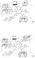
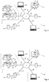
- a communication network is designated by the reference numeral 1.
- the communication network 1 may be formed as any network for transmitting data, in particular as the Internet.
- the communication network 1 is in FIG. 1 only symbolically represented as a cloud. However, the exact configuration of the communication network 1 is known to the person skilled in the art from the prior art.
- the machine tools 2 to 5 are spatially preferably arranged at different locations 6, 7, 8.
- the different locations 6 to 8 can be different companies or company locations.
- the machine tools 2, 3 are indirectly via an internal company Server 9 connected to the communication network 1.
- the data transmission between the machine tools 2, 3 and the server 9 via data transmission lines 10, 11 can take place according to any transmission protocol.
- data transmission by means of an in-house proprietary protocol or the IP (Internet Protocols) is intended.
- the data transmission between the server 9 and the communication network 1 via a data transmission connection 12 can also take place according to any data transmission protocol. If the communication network 1 is designed as the Internet, the data transmission via the data connection 12 preferably takes place according to the IP.
- the server 9 is preferably formed as an Internet server.
- other machine tools may be connected to the server 9, which is indicated by the three points between the machine tools 2 and 3.
- the other machine tools connected to the server 9 can likewise be arranged within the location 6 or spatially separated therefrom, for example in another company or company location.
- the machine tool 4 and optionally further machine tools which is indicated by the three points to the right of the machine tool 4, are arranged at the location 7 and connected via a data transmission connection 13 directly to the communication network 1.
- the data transmission between the machine tool 4 and the communication network 1 via the data connection 13 takes place according to any protocol, in particular according to the IP.
- the machine tool 4 has a suitable interface 14 with hardware and software to fulfill the interface function.
- the machine tool 5 as well as possibly other machine tools, what by the three points below the Machine tool 5 is indicated, arranged at the location 8.
- the machine tool 5 and optionally the other machine tools of the site 8 are connected via a data transmission connection 15 directly to the communication network 1.
- the data transmission between the machine tool 5 and the communication network 1 via the data connection 15 can take place according to any protocol, in particular according to the IP.
- the machine tool 5 therefore has a suitable interface 16, which detects hardware and software to fulfill the interface function.
- the connected machine tools 2 to 5 are preferably designed as machine tools for machining workpieces.
- the machine tools 2 to 5 are designed in particular for drilling, turning, milling, honing, grinding, lapping, finishing or sawing and have corresponding tools.
- Each of the machine tools 2 to 5 has usually stored a plurality of tools in a tool magazine and is equipped for a desired machining step with the appropriate tool for machining the workpiece.
- the machine tools can have so-called turret mounts, which can be equipped with several tools.
- a server 19 is also connected to the communication network 1 via a data transmission connection 20.
- the server 19 has access to one or more databases 21, 22.
- the databases 21, 22 may be connected either directly to the server 19, as is the case for example with the database 21, which via a data transmission connection 23 with the server 19 in Connection stands. It is even conceivable that the database 21 is an integral part of the server 19.
- the databases 21, 22 may also be connected to the communication network 1, as is the case, for example, with the database 22 which is in communication with the communication network 1 via a data transmission connection 24.
- the server 19 accesses the database 22 via the data links 20, 24 and the communication network.
- more than the illustrated databases 21, 22 may be connected to the server 19 or the communication network 1, to which the server 19 has access.
- a client 25 is connected to the communication network 1 via a communication link 26.
- the tool holder 17 and / or the tools 18 of the machine tools 2 to 5 are provided as comprehensively as possible with each of the tool holder 17 or tools 18 uniquely assigned identification data.
- the identification data comprise any number and / or letter combination.
- the identification data may be in the form of a bar code, a data matrix, a QR code, an RFID tag or similar storage means be stored.
- the storage means are preferably arranged on or in the tool holders 17 or the tools 18.
- the machine tools 2 to 5 have suitable read-in means for reading in the identification data of the tool holders 17 or of the tools 18 without contact.
- the read-in means 27 work optically in the case of bar codes, data matrix or QR codes, preferably by radio in the case of RFID labels.
- the machine tools 2 to 5 transmit the identification data of the tool holders 17 or of the tools 18 to the server 19.
- static information associated with the identification data is stored via the tools 18.
- This information includes, for example, the type of tools 18 (eg, drill, lathe, cutter, honing tool, grindstone or disc, reaming tool, finishing belt or stone or saw), the manufacturer of the tool, the material of the tool, number, type and design of interchangeable cutting plates, cutting data recommendations for the tool, inspection programs for the tool, drawings or technical specifications of the tool, collision viewing models (2D, 3D), etc.
- the server 19 can uniquely identify what tools it is in the observed tools or in the tools used by the observed machine tools.
- any other information from the machine tools 2 to 5 can also be transmitted to the server 19.
- Such information includes, for example, identification data and / or operating parameters of Machine tools 2 to 5.
- the server 19 by means of the identification data associated additional, stored in the databases 21, 22 information can determine exactly what type of machine tools.
- the operating parameters of the machine tools 2 to 5 include, for example, the rotational speed, the feed rate, an operating time, etc. This type of data is subject to changes in time, so they are referred to as dynamic information.
- the server 19 also has means for processing the received dynamic information, the static information from the databases 21, 22 and / or the operating parameters of the machine tools 2 to 5. By means of a suitable evaluation and processing of the received information and parameters, the server 19 generate updated information about the tools 18. It is crucial that in the server 19 a wealth of different information from a variety of tools 18 and machine tools 2 to 5 is brought together. This wealth of data and the fact that it is available at a central location, namely at the server 19, makes it possible for the first time to generate updated information about the tools 18, the information content of the updated information about the sum of the information content of the received data dynamic information that goes beyond static information from the databases 21, 22 and the operating parameters.
- the server according to the invention thus offers real information-related added value over the prior art, which can be used both by the tool manufacturers and by any third parties to improve and optimize the production and service processes.
- the client 25 may be located anywhere on the network 1. Thus, for example, it is conceivable that the client 25 in a company at any location, for example.
- the location 7 (see. FIG. 2 ) is arranged.
- the enterprise receives over the client 25 by access on the server 19 via the network 1 value-added information with respect to the tool 18, for example, a recommendation for optimal use ("best-practice") of the tool 18, cutting data recommendations, collision viewing models (2D, 3D), etc ..
- the client 25 at a tool manufacturer 28 (see FIG. FIG. 3 ) is arranged.
- the causes of a tool failure can be found more easily by assigning measured values, production data, etc. to specific tools 18 in the event of a complaint on the part of the tool user. Additional possibilities exist, for example, in a targeted recall of a particular batch of manufactured tools 18.
- the client 25 at a regrinding service 29 (see FIG. FIG. 4 ) is arranged.
- the individual codes of the tools 18 allow downloading of corresponding drawings, information on the cutting material / coating, of machine programs, the number of previous and / or possible re-grindings, customer information, original order numbers, etc. from the server 19 via the Network 1.
- information about the tool 18 itself can be retrieved from the server 19 for tool preparation, for example. Usage parameters such as time of use, distance covered, number of machined workpieces, number of generated during the previous operation (error) data, etc.
- the tool 18 is assigned, defined data in the database 21; 22, which shows that a preparation of the tool 18 has been carried out and the nature and extent of the treatment.
- the database 21 22 shows that a preparation of the tool 18 has been carried out and the nature and extent of the treatment.
- clients 25 access to the Server 19 and the data stored therein and value-added information.
- the updated data with the added value of information content can be used by the machine tools 2 to 5 in the company, but also by outside the company arranged machine tools, as well as any processing machines for reprocessing of tools, regrinding machines, Voreinstelltechnikn, measuring systems, etc.
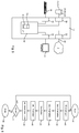
- the server 19 is in FIG. 5 shown in detail. It comprises an interface 30 for communication and data exchange with the databases 21, 22.
- the interface 30 is controlled and managed by a database application which is part of a software 31 running on a microprocessor 32 of the server 19.
- the server 19 has an interface 33 for connecting the server to the communication network 1.
- the interface 33 is likewise controlled and managed by a software 31 executable on the microprocessor 32 or by a part thereof.
- the server 19 has an interface 34 via which input means are connected, for example in the form of a keyboard 35, a computer mouse.
- the control and administration of the interface 34 also takes place via a part of the software 31, in particular via an operating system of the microprocessor 32.
- the server 19 has an interface 36 via which output units, for example in the form of a computer screen 37, are connected.
- the interface 36 is also controlled by a part of the software 31, in particular by the operating system of the microprocessor 32.
- the processing means of the server 19, which receives the received identification data of the tools 18 and the machine tools 2 to 5, the dynamic information also received from the machine tools 2 to 5 and optionally further information or data from the machine tools 2 to 5 and based on the received identification data the databases 21, 22 taken static information of the corresponding tools 18 are realized in the server 19 in the form of the software 31 and a part 31a thereof.
- the software processing means 31a are executable on the microprocessor 32 and realize the desired evaluation and processing of said information for generating the updated information about the tools 18.
- the processing or evaluation of the information by the software part 31a comprises in particular a statistical evaluation, which also includes a reliable statement about the future of tools 18 allowed.
- the updated information may also include information on the duration of use and type of use of the tools 18 and the respective resulting service lives of the tools 18.
- the updated information generated in the server 19 with the added value contained therein can be stored in one or more of the databases 21, 22. It is also conceivable that the updated information or a part thereof is transmitted back to the machine tools 2 to 5. It is also conceivable that third parties have access via the client 25 to the information stored in the databases 21, 22, including the updated information. In this way, 18 tooling times, cutting data, collision viewing models, test programs, drawings or technical specifications can be downloaded for the desired tools. Third parties who seek access to the server 19 or the databases 21, 22 via the client 25 are, for example, the operators of the machine tools 2 to 5 at the various locations 6 to 8. Alternatively, the third parties may also be the manufacturers of the tools 18 which By optimizing their updated information, they can optimize their performance Hoping for manufacturing processes.
- the server 19 Before third parties receive access to the server 19 or the contents stored in the databases 21, 22 via the client 25, the server 19 can check their authorization. In this way, the updated information generated by the server 19 as well as the data stored in the databases 21, 22 with respect to the tools 18 can be offered to third parties at a charge, so that the great expense for the installation of the infrastructure described and for the purchase and maintenance of the infrastructure required costs are at least partially paid by the user charges of third parties.
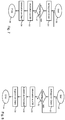
- FIG. 6 shows a software routine of the software 31, through which the static and dynamic information and the operating parameters of the machine tools 2 to 5 and possibly further information processed and evaluated and the updated information is generated.
- the method comprises, for example, the following steps: Start of the method in step 40.
- a step 41 the identification data of the tools 18, the tool holder 17 and / or the machine tools 2 to 5 are received.
- the dynamic information regarding the tools 18 is received.
- the static information corresponding to the received identification data is loaded from one or more of the databases 21, 22.
- step 44 then the actual processing of the received or loaded data and information in the server 19 to generate the updated information 45.
- the updated information can either in the server 19 for retrieval by a third party, eg.
- a query step 47 a query is made as to whether the routine should be ended, for example at the behest of the operator of the server 19. If so, the processing routine is ended in step 48. Otherwise, a branch is made back to step 41 and steps 41 through 47 are repeated.
- FIG. 7 is a flowchart of a software routine of the software 31; FIG. which causes a query to the server 19 and the databases 21, 22 by the client 25.
- the method comprises, for example, the following steps: Start of the method in step 50.
- the client 25 starts a query to the server 19.
- the query includes an authorization code of the client 25.
- the validity of the authorization code is queried. If the client 25 is authorized to download the requested information, the requested information is retrieved from the database 21 in a step 53; 22 loaded and transmitted in a step 54 to the client. Otherwise, a branch is made back to the step 51.
- the polling routine is ended.
- Information about the requested information may either be included in the request of the client 25 or stored in the server for the customer identified by the authorization code.
- FIG. 3 shows a further exemplary embodiment of a flow chart of a software routine of the software 31 which causes a query to the server 19 or the databases 21, 22 by the client 25.
- a further step 56 is provided between step 53 (load information / data from database 21, 22) and step 54 (transfer information / data loaded from database 21, 22 to client 25).
- the client 25, together with its request (step 51), can immediately order a desired evaluation of the data by the server 19.
- various standard processing algorithms are present in the server 19 in this embodiment, of which the client 25 can select one or more.
- the algorithms selected by the client 25 are transmitted to the server 19 along with the request.
- step 56 the evaluation or processing of the data base 21 then takes place; 22 loaded information / data according to the desired algorithms instead.
- the result of the evaluation or the processed data is then transmitted to the client 25 in step 54.
- This has the advantage that a computationally intensive and memory-intensive evaluation / processing of Information / data from the database 21; 22 at the client 25 is no longer necessary. This can thus be made smaller and cheaper. Under certain circumstances, data transmission capacity can be saved via the network 1, since not all from the database 21; 22 read data / information must be sent to the client 25, but only the result of the evaluation or the processed data.
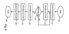
- FIG. 9 finds the evaluation or processing of the data / information from the database 21; 22 not at the server, but locally at the client 25 instead.
- at least one desired algorithm for evaluating / processing data is first selected at the client 25 in a step 57.
- the data / information required for the selected algorithm is made the subject of a request to the client 25, which is transmitted in step 51.
- the data / information required for the selected algorithm can either be input manually by the user of the client 25 or automatically determined by the client 25 based on the selected algorithm.
- the processing of the query at the server 19 is carried out in a similar manner as above for the embodiment FIG. 7 described.
- the data / information transmitted by the server 19 to the client 25 (step 54) is then evaluated / processed at the client 25 according to the algorithm previously selected in step 57, so that the client 25 now has the desired information.
Claims (18)
- Serveur (19) d'un réseau de communication (1), qui est connecté au réseau de communication (1) via une liaison de communication (20) et qui exécute une application de base de données avec accès à une base de données (21; 22) conçue pour collecter et gérer des données, ledit serveur (19) étant en communication via le réseau de communication (1), directement ou indirectement via d'autres serveurs (9) du réseau de communication (1), avec une pluralité de machines (2, 3, 4, 5) ou dispositifs associé(e)s à des sociétés (6, 7, 8) différentes et internes aux sociétés et destiné(e)s à l'utilisation ou au retraitement d'outils (18), caractérisé par le fait que les outils (18) sont conçus pour l'usinage à enlèvement de copeaux de pièces à usiner, que les outils (18) comprennent chacun une pluralité d'éléments, dans lequel à au moins certains des éléments sont associées des données d'identification individuelles, que le serveur (19) comprend des moyens de réception de données provenant d'outils (18) des machines (2, 3, 4, 5) ou des dispositifs et/ou d'informations dynamiques relatives aux outils (18), dans lequel les moyens de réception sont conçus pour recevoir des données d'identification individuelles des éléments des outils (18), et le serveur (19) comprend des moyens pour un stockage des données reçues dans la base de données (21, 22), qui est associé aux outils correspondants, que le serveur (19) présente des moyens de traitement des données reçues et d'autres données stockées dans la base de données (21 ; 22) afin de générer des données relatives aux outils (18) et mises à jour, dans lequel le contenu d'information des données mises à jour dépasse la somme du contenu d'information des données reçues et des autres données stockées dans la base de données (21 ; 22), que les moyens de traitement assemblent, en tant que données mises à jour, des outils virtuels correspondant aux outils (18), à partir des éléments correspondant aux données d'identification individuelles mises en mémoire, et que le serveur (19) présente des moyens pour stocker, dans la base de données (21 ; 22), les données mises à jour générées.
- Serveur (19) selon la revendication 1, caractérisé par le fait que la machine ou le dispositif destiné(e) à l'utilisation ou au retraitement d'outils (18) comprend une machine-outil (2, 3, 4, 5) et/ou un autre dispositif de réaffûtage, de revêtement ultérieur, de contrôle, de mesure ou d'évaluation de l'outil (18) et/ou de pièces à usiner.
- Serveur (19) selon la revendication 1 ou 2, caractérisé par le fait que les données reçues des moyens de réception du serveur (19) et relatives à des outils (18) des machines-outils (2, 3, 4, 5) et/ou des autres dispositifs de retraitement d'outils (18) et/ou de pièces à usiner comprennent des données d'identification des outils (18) des machines-outils (2, 3, 4, 5) et/ou des autres dispositifs de retraitement d'outils (18) et/ou de pièces à usiner.
- Serveur (19) selon la revendication 2 ou 3, caractérisé par le fait que les données - reçues des moyens de réception du serveur (19) - des machines-outils (2, 3, 4, 5) et/ou des autres dispositifs de retraitement d'outils (18) et/ou de pièces à usiner comprennent des données d'identification et/ou paramètres de service des machines-outils (2, 3, 4, 5) et/ou des autres dispositifs de retraitement d'outils (18) et/ou de pièces à usiner, des informations de machine typologiques et/ou des informations de pièce à usiner et/ou de matériau.
- Serveur (19) selon l'une quelconque des revendications 1 à 4, caractérisé par le fait que les autres données stockées dans la base de données (21 ; 22) comprennent des informations statiques relatives aux outils (18) et associées aux données reçues du serveur (19).
- Serveur (19) selon l'une quelconque des revendications 1 à 5, caractérisé par le fait que les moyens de réception sont conçus également pour recevoir des informations de fabricant relatives aux outils (18) provenant d'autres serveurs de fabricants des outils (18), qui sont connectés au réseau de communication (1), et que les moyens de traitement sont conçus pour générer les informations mises à jour également en fonction des informations de fabricant.
- Serveur (19) selon l'une quelconque des revendications 1 à 6, caractérisé par le fait que les moyens de réception sont conçus également pour recevoir des informations de prestataire de service relatives aux outils (18) et provenant d'autres serveurs connectés au réseau de communication (1), de prestataires de service qui apportent des modifications aux outils (18), et que les moyens de traitement sont conçus pour générer les informations mises à jour également en fonction des informations de prestataire de service.
- Serveur (19) selon l'une quelconque des revendications 1 à 7, caractérisé par le fait que le serveur (19) comprend des moyens pour transmettre les données mises à jour générées à d'autres serveurs de fabricants d'outils pour mettre à jour des informations de fabricant y stockées.
- Serveur (19) selon l'une quelconque des revendications 1 à 8, caractérisé par le fait qu'un logiciel de programmation des machines-outils (2, 3, 4, 5) et/ou des autres dispositifs de retraitement d'outils (18) et/ou de pièces à usiner est mémorisé dans la base de données (21 ; 22), les moyens de traitement étant conçus également pour générer un logiciel mis à jour sur la base des informations mises à jour, et le serveur (19) présente des moyens de transmission du logiciel mis à jour aux machines-outils (2, 3, 4, 5) et/ou aux autres dispositifs de retraitement d'outils (18) et/ou de pièces à usiner via le réseau de communication (1).
- Serveur (19) selon la revendication 9, caractérisé par le fait que le logiciel comprend des recommandations de données de coupe, des programmes de réglage pour les machines-outils (2, 3, 4, 5) et/ou des modèles d'observation de collision.
- Serveur (19) selon l'une quelconque des revendications 1 à 10, caractérisé par le fait que les informations mises à jour générées par les moyens de traitement du serveur (19) comprennent des renseignements prospectifs relatifs aux outils (18) utilisés, à des porte-outils (17) correspondants et/ou aux machines-outils (2, 3, 4, 5).
- Serveur (19) selon l'une quelconque des revendications 1 à 11, caractérisé par le fait que les informations mises à jour générées comprennent des durées de service d'outil, la fréquence d'utilisation, la durée d'utilisation, les temps de changement, les données de coupe, la qualité de composant de composants fabriqués avec les outils (18) et/ou des données relatives à des plaquettes de coupe utilisées.
- Serveur (19) selon l'une quelconque des revendications 1 à 12, caractérisé par le fait que les moyens de traitement sont conçus pour traiter les informations dynamiques reçues, les informations statiques issues de la base de données (21 ; 22) et/ou les paramètres de service des machines-outils (2, 3, 4, 5) au moyen d'un réseau neuronal, d'une formation de groupe et/ou d'une évaluation statistique.
- Serveur (19) selon l'une quelconque des revendications 1 à 13, caractérisé par le fait que le serveur (19) comprend des moyens de transmission de données et d'informations mémorisées dans la base de données (21 ; 22) et/ou des données mises à jour générées à au moins un client (25) qui est en communication avec le serveur (19) via le réseau de communication (1).
- Serveur (19) selon la revendication 14, caractérisé par le fait que le serveur (19) comprend des moyens de contrôle d'une autorisation du client (25) pour accéder aux données et informations stockées dans la base de données (21 ; 22) et/ou aux données mises à jour générées.
- Serveur (19) selon la revendication 14 ou 15, caractérisé par le fait que sur le serveur (19) est prévue une interface utilisateur graphique via laquelle le client (25) peut accéder aux données et informations stockées dans la base de données (21 ; 22) et/ou aux données mises à jour générées.
- Serveur (19) selon l'une quelconque des revendications 1 à 16, caractérisé par le fait que le serveur (19) forme un dispositif de régulation d'une boucle de régulation fermée.
- Serveur (19) selon la revendication 17, caractérisé par le fait qu'un système asservi de la boucle de régulation est constitué par la machine ou le dispositif d'utilisation de l'outil (18), un dispositif de mesure de la boucle de régulation est constitué par un capteur et/ou un modèle de l'insert d'outil et un actionneur de la boucle de régulation est constitué par une machine ou un dispositif destiné à produire au moins un élément d'un outil du même type que l'outil (18) inséré, dans lequel le dispositif de mesure saisit des données de l'outil (18) ou du porte-outil (17) de la machine-outil (2, 3, 4, 5) et/ou des données de la machine-outil (2, 3, 4, 5) et/ou des informations dynamiques relatives à l'outil (18) et transmet celles-ci en tant que grandeur(s) de signal via ledit réseau de communication (1) au serveur (19), les moyens de traitement du serveur (19) déterminent une différence de régulation à partir des données ou bien informations reçues, à partir des données stockées dans la base de données (21 ; 22) et à partir d'au moins une grandeur de référence, et les moyens de traitement du serveur (19) comprennent un régulateur qui détermine, à partir de la différence de régulation, une grandeur de signal pour l'actionneur et transmet celle-ci à ce dernier.
Priority Applications (1)
| Application Number | Priority Date | Filing Date | Title |
|---|---|---|---|
| SI201131794T SI2494475T1 (sl) | 2010-11-25 | 2011-10-31 | Strežnik računalniške mreže |
Applications Claiming Priority (5)
| Application Number | Priority Date | Filing Date | Title |
|---|---|---|---|
| DE202010017375U DE202010017375U1 (de) | 2010-11-25 | 2010-11-25 | Server eines Computernetzwerks |
| DE102010052556 | 2010-11-25 | ||
| US201161510816P | 2011-07-22 | 2011-07-22 | |
| DE102011108361A DE102011108361A1 (de) | 2010-11-25 | 2011-07-22 | Server eines Computernetzwerks |
| PCT/EP2011/069100 WO2012069284A1 (fr) | 2010-11-25 | 2011-10-31 | Serveur d'un réseau d'ordinateurs |
Publications (2)
| Publication Number | Publication Date |
|---|---|
| EP2494475A1 EP2494475A1 (fr) | 2012-09-05 |
| EP2494475B1 true EP2494475B1 (fr) | 2019-09-04 |
Family
ID=44910200
Family Applications (1)
| Application Number | Title | Priority Date | Filing Date |
|---|---|---|---|
| EP11779381.0A Revoked EP2494475B1 (fr) | 2010-11-25 | 2011-10-31 | Serveur d'un réseau d'ordinateurs |
Country Status (10)
| Country | Link |
|---|---|
| US (1) | US9460170B2 (fr) |
| EP (1) | EP2494475B1 (fr) |
| JP (1) | JP5959525B2 (fr) |
| KR (1) | KR101711237B1 (fr) |
| CN (2) | CN102870112A (fr) |
| BR (1) | BR112012015830A8 (fr) |
| CA (1) | CA2782273C (fr) |
| IL (1) | IL220577A (fr) |
| SI (1) | SI2494475T1 (fr) |
| WO (1) | WO2012069284A1 (fr) |
Families Citing this family (25)
| Publication number | Priority date | Publication date | Assignee | Title |
|---|---|---|---|---|
| CN102841571B (zh) * | 2012-07-23 | 2014-11-05 | 沈阳海默数控机床有限公司 | 一种机床质量信息管理系统 |
| KR101703466B1 (ko) * | 2013-04-10 | 2017-02-06 | 미쓰비시덴키 가부시키가이샤 | 수치 제어 장치, 정보 제휴 시스템 및 정보 제휴 프로그램이 기록된 컴퓨터로 판독 가능한 매체 |
| JP6939053B2 (ja) * | 2016-07-15 | 2021-09-22 | 株式会社リコー | 診断装置、プログラムおよび診断システム |
| TWI610738B (zh) | 2016-08-19 | 2018-01-11 | 財團法人工業技術研究院 | 工具機刀具管理系統與方法 |
| DE102016219371A1 (de) * | 2016-10-06 | 2018-04-12 | Homag Gmbh | Bearbeitungsverfahren, Datenbankserver, System und Verfahren zum Teilen von Daten für Bearbeitungsvorrichtungen mittels Datenfernübertragung |
| CN110392614B (zh) * | 2017-03-09 | 2021-06-11 | 花王株式会社 | 铸造支援系统 |
| TWI670672B (zh) * | 2017-03-24 | 2019-09-01 | 國立成功大學 | 雲製造服務的自動建置方法、電腦程式產品、雲製造系統 |
| DE102017126434A1 (de) * | 2017-11-10 | 2019-05-16 | Keuro Besitz Gmbh & Co. Edv-Dienstleistungs Kg | Werkzeugmaschine, insbesondere Sägemaschine, und System für einen optimierten Betrieb einer Werkzeugmaschine |
| CN107942929B (zh) * | 2017-12-13 | 2020-08-28 | 深圳普菲特信息科技股份有限公司 | 基于神经网络计算技术的数控车床的控制方法 |
| JP6813521B2 (ja) | 2018-02-08 | 2021-01-13 | ファナック株式会社 | 温度計測装置 |
| US10564624B2 (en) | 2018-02-16 | 2020-02-18 | General Electric Company | Optimal machining parameter selection using a data-driven tool life modeling approach |
| EP3537239A1 (fr) * | 2018-03-06 | 2019-09-11 | Siemens Aktiengesellschaft | Procédé d'utilisation d'une machine-outil au moyen de l'adaptation d'un modèle de données précompilé |
| JP6777672B2 (ja) * | 2018-04-03 | 2020-10-28 | Dmg森精機株式会社 | 情報処理装置、情報処理方法および情報処理プログラム |
| GB2573273B (en) * | 2018-04-05 | 2020-09-30 | Nikken Kosakusho Europe Ltd | System And Method For Monitoring Characteristics Of A Rotary Table |
| CN110657745B (zh) * | 2018-06-29 | 2021-10-01 | 富泰华精密电子(郑州)有限公司 | 装刀管理系统、装刀管理方法及存储设备 |
| CN113272746B (zh) * | 2019-05-09 | 2024-04-09 | 西门子股份公司 | 基于刀具更换记录的切削刀具寿命的设置方法、装置和系统 |
| JP6738466B1 (ja) * | 2019-06-28 | 2020-08-12 | Dmg森精機株式会社 | 情報処理装置、情報処理方法および情報処理プログラム |
| EP3757697B1 (fr) * | 2019-06-28 | 2022-08-10 | Seco Tools Ab | Dispositif électronique et procédé de gestion de la traçabilité d'un outil de coupe |
| US11112783B2 (en) * | 2019-10-25 | 2021-09-07 | Computational Systems, Inc. | Method and apparatus for machine monitoring with continuous improvement of a predictive maintenance database |
| KR102302798B1 (ko) * | 2019-11-27 | 2021-09-16 | 현대위아 주식회사 | 공작기계 이상상태 모니터링 시스템 및 방법 |
| CN111181926B (zh) * | 2019-12-13 | 2022-04-05 | 中国人民解放军战略支援部队信息工程大学 | 一种基于拟态防御思想的安全设备及其运行方法 |
| AU2021218872B2 (en) * | 2020-02-13 | 2024-03-07 | Bobst Mex Sa | Tool insert for a machine, machine, and method for operating a machine |
| US20220155764A1 (en) * | 2020-11-18 | 2022-05-19 | The Boeing Company | Continuous flow manufacturing system and apparatus and method for controlling a continuous flow manufacturing process |
| CN114515977B (zh) * | 2022-02-23 | 2023-06-06 | 河南航天精工制造有限公司 | 一种自动化产线自动补偿系统及方法 |
| CN115660019B (zh) * | 2022-12-26 | 2023-06-02 | 帕莱克机械(南京)有限公司 | 一种基于云计算平台的刀具数据监管系统及其方法 |
Citations (7)
| Publication number | Priority date | Publication date | Assignee | Title |
|---|---|---|---|---|
| US20030023336A1 (en) * | 2001-07-13 | 2003-01-30 | Volker Kreidler | System architecture and method for network-delivered automation-related content |
| DE102004048695A1 (de) * | 2003-10-09 | 2005-05-12 | Mori Seiki Seisakusho Kk | System zur Verwaltung des Betriebszustands von Werkzeugmaschinen |
| DE112004000349T5 (de) * | 2003-02-28 | 2006-02-16 | Mori Seiki Co., Ltd., Yamatokoriyama | Betriebsverwaltungssystem |
| WO2007143005A2 (fr) * | 2006-05-31 | 2007-12-13 | Active Automation, Inc. | système et procédé rentables pour surveiller des unités de machinerie |
| US20090177452A1 (en) | 2008-01-08 | 2009-07-09 | Immersion Medical, Inc. | Virtual Tool Manipulation System |
| US20100095824A1 (en) | 2008-10-18 | 2010-04-22 | Trumpf Werkzeugmaschinen Gmbh + Co. Kg | Reprocessed Dies |
| CN101770222A (zh) | 2010-03-09 | 2010-07-07 | 江南大学 | 数控机床刀具的在线管理方法 |
Family Cites Families (19)
| Publication number | Priority date | Publication date | Assignee | Title |
|---|---|---|---|---|
| JPH074732B2 (ja) * | 1985-09-11 | 1995-01-25 | オムロン株式会社 | 工具識別装置 |
| DE3681384D1 (de) | 1985-09-11 | 1991-10-17 | Omron Tateisi Electronics Co | Vorrichtung zum erkennen von werkzeugen und zum verwalten von werkzeugdaten. |
| JP2993608B2 (ja) * | 1989-12-11 | 1999-12-20 | ファナック株式会社 | 工具補正方法 |
| JPH09269808A (ja) * | 1996-03-29 | 1997-10-14 | Fanuc Ltd | Cncデータ補正方法 |
| US6385502B1 (en) * | 1998-03-31 | 2002-05-07 | Ntn Corporation | Race groove machining system and method therefor |
| JP2001075624A (ja) * | 1999-07-01 | 2001-03-23 | Mori Seiki Co Ltd | Nc工作機械のツールパスデータ生成装置及びこれを備えた数値制御装置 |
| US6401056B1 (en) * | 1999-12-27 | 2002-06-04 | General Electric Company | Methods and apparatus for evaluating tool performance |
| US20020133264A1 (en) * | 2001-01-26 | 2002-09-19 | New Jersey Institute Of Technology | Virtual reality system for creation of design models and generation of numerically controlled machining trajectories |
| DE10243771A1 (de) * | 2002-09-20 | 2004-04-22 | Siemens Ag | Vorrichtung zur Automatisierung und/oder Steuerung von Werkzeug- oder Produktionsmaschinen |
| JP2004265034A (ja) * | 2003-02-28 | 2004-09-24 | Mori Seiki Co Ltd | 稼働管理システム |
| US20060004786A1 (en) * | 2004-06-07 | 2006-01-05 | Taiwan Semiconductor Manufacturing Company Ltd. | Design mechanism for semiconductor fab-wide data warehouse application |
| US7378973B2 (en) * | 2005-03-29 | 2008-05-27 | Emerson & Cuming Microwave Products, Inc. | RFID tags having improved read range |
| JP4799114B2 (ja) * | 2005-10-06 | 2011-10-26 | 中村留精密工業株式会社 | Nc工作機械の制御プログラムの更新方法及び装置 |
| JP4263197B2 (ja) * | 2006-03-27 | 2009-05-13 | 株式会社東芝 | 監視ソフトウェア作成装置、監視システム、監視ソフトウェア作成方法および監視ソフトウェア作成プログラム |
| JP2008296301A (ja) * | 2007-05-30 | 2008-12-11 | General Electric Co <Ge> | 機械加工ツールを測定し、そこから生成されたデータを使用するシステムおよび方法 |
| DE102007030396B4 (de) * | 2007-06-29 | 2014-11-27 | Trumpf Werkzeugmaschinen Gmbh + Co. Kg | Vorrichtung zur Steuerung einer Maschine sowie Fernkommunikationssystem |
| CN101334656B (zh) * | 2008-07-25 | 2010-08-04 | 华中科技大学 | 一种数控机床加工性能监控系统 |
| CN101592950A (zh) * | 2009-06-05 | 2009-12-02 | 南通职业大学 | 一种基于web的数控编程与仿真服务系统 |
| CN101592938A (zh) * | 2009-06-30 | 2009-12-02 | 刘文祥 | 数控网络及其各种系统 |
-
2011
- 2011-10-31 BR BR112012015830A patent/BR112012015830A8/pt not_active Application Discontinuation
- 2011-10-31 CA CA2782273A patent/CA2782273C/fr not_active Expired - Fee Related
- 2011-10-31 KR KR1020127016703A patent/KR101711237B1/ko active IP Right Grant
- 2011-10-31 CN CN2011800214749A patent/CN102870112A/zh active Pending
- 2011-10-31 WO PCT/EP2011/069100 patent/WO2012069284A1/fr active Application Filing
- 2011-10-31 JP JP2013540290A patent/JP5959525B2/ja not_active Expired - Fee Related
- 2011-10-31 CN CN201710206402.0A patent/CN107463594A/zh active Pending
- 2011-10-31 EP EP11779381.0A patent/EP2494475B1/fr not_active Revoked
- 2011-10-31 SI SI201131794T patent/SI2494475T1/sl unknown
- 2011-11-22 US US13/302,206 patent/US9460170B2/en active Active
-
2012
- 2012-06-21 IL IL220577A patent/IL220577A/en active IP Right Grant
Patent Citations (8)
| Publication number | Priority date | Publication date | Assignee | Title |
|---|---|---|---|---|
| US20030023336A1 (en) * | 2001-07-13 | 2003-01-30 | Volker Kreidler | System architecture and method for network-delivered automation-related content |
| DE112004000349T5 (de) * | 2003-02-28 | 2006-02-16 | Mori Seiki Co., Ltd., Yamatokoriyama | Betriebsverwaltungssystem |
| US20060149412A1 (en) | 2003-02-28 | 2006-07-06 | Mori Seiki Co., Ltd. | Operation management system |
| DE102004048695A1 (de) * | 2003-10-09 | 2005-05-12 | Mori Seiki Seisakusho Kk | System zur Verwaltung des Betriebszustands von Werkzeugmaschinen |
| WO2007143005A2 (fr) * | 2006-05-31 | 2007-12-13 | Active Automation, Inc. | système et procédé rentables pour surveiller des unités de machinerie |
| US20090177452A1 (en) | 2008-01-08 | 2009-07-09 | Immersion Medical, Inc. | Virtual Tool Manipulation System |
| US20100095824A1 (en) | 2008-10-18 | 2010-04-22 | Trumpf Werkzeugmaschinen Gmbh + Co. Kg | Reprocessed Dies |
| CN101770222A (zh) | 2010-03-09 | 2010-07-07 | 江南大学 | 数控机床刀具的在线管理方法 |
Also Published As
| Publication number | Publication date |
|---|---|
| KR20130142054A (ko) | 2013-12-27 |
| CN102870112A (zh) | 2013-01-09 |
| JP5959525B2 (ja) | 2016-08-02 |
| CA2782273A1 (fr) | 2012-05-31 |
| SI2494475T1 (sl) | 2020-02-28 |
| US20120303674A1 (en) | 2012-11-29 |
| WO2012069284A1 (fr) | 2012-05-31 |
| JP2013546079A (ja) | 2013-12-26 |
| CA2782273C (fr) | 2018-08-21 |
| EP2494475A1 (fr) | 2012-09-05 |
| BR112012015830A8 (pt) | 2018-07-03 |
| CN107463594A (zh) | 2017-12-12 |
| BR112012015830A2 (pt) | 2017-04-25 |
| KR101711237B1 (ko) | 2017-02-28 |
| IL220577A (en) | 2017-05-29 |
| US9460170B2 (en) | 2016-10-04 |
Similar Documents
| Publication | Publication Date | Title |
|---|---|---|
| EP2494475B1 (fr) | Serveur d'un réseau d'ordinateurs | |
| CN108492016B (zh) | 一种刀具管理方法 | |
| DE102011108361A1 (de) | Server eines Computernetzwerks | |
| DE10120173A1 (de) | Verfahren und Vorrichtung zum Betreiben von Landmaschinen | |
| DE19740974A1 (de) | Buchfertigungssystem | |
| WO2007090486A1 (fr) | Systeme de determination de l'état d'usure d'une machine-outil | |
| DE102007039531A1 (de) | Verfahren zum Beschaffen von instandhaltungsrelevanten Informationen zu einer Anlage | |
| EP3304404B1 (fr) | Procédé de fabrication de pièces de rechange de machines d'emballage | |
| CN101939710A (zh) | 用于轧机的rfid系统及轴承部件 | |
| DE102019210186A1 (de) | Datenverwaltungseinrichtung, datenverwaltungsverfahren und datenverwaltungsprogramm | |
| DE102017003426A1 (de) | Anlagenverwaltungseinheit, die mehrere Fertigungsanlagen mit Nachschub versorgt, und Produktionssystem | |
| DE102010054744A1 (de) | Schneidwerkzeug zu gewerblichen Zwecken in Kombination mit einer EDV-Anlage | |
| EP2616223A1 (fr) | Procédé permettant d'éviter les défaillances et les pièces défectueuses lors du fonctionnement d'une machine de fabrication | |
| DE102019105745A1 (de) | Produktionsmanagementsystem | |
| DE202010017375U1 (de) | Server eines Computernetzwerks | |
| DE102017005674B4 (de) | Zellenfertigungssystem mit Fertigungszelle für autonome Fertigung | |
| EP3056956A1 (fr) | Procede de commande decentralisee de machines d'usinage | |
| WO2017054820A1 (fr) | Procédé et système de gestion de données relatives à un palier | |
| DE102018201083A1 (de) | Informationsverwaltungssystem, server, informationsverwaltungsverfahren und programm | |
| DE102019213003A1 (de) | Wissensbereitstellungsprogramm, wissensbereitstellungsvorrichtung und betriebsdienstsystem | |
| DE102019213001A1 (de) | Wissensproduktionssystem | |
| Rouabhia-Essalhi et al. | An approach to implement internal traceability in machining workshops | |
| WO2023186800A1 (fr) | Procédé permettant de prouver des enregistrements de données d'outil pour des outils d'usinage | |
| WO2011092086A1 (fr) | Assurance de la qualité de processus industriels de production et de montage | |
| DE10130737A1 (de) | Einstellsystem für Werkzeuge |
Legal Events
| Date | Code | Title | Description |
|---|---|---|---|
| PUAI | Public reference made under article 153(3) epc to a published international application that has entered the european phase |
Free format text: ORIGINAL CODE: 0009012 |
|
| 17P | Request for examination filed |
Effective date: 20120524 |
|
| AK | Designated contracting states |
Kind code of ref document: A1 Designated state(s): AL AT BE BG CH CY CZ DE DK EE ES FI FR GB GR HR HU IE IS IT LI LT LU LV MC MK MT NL NO PL PT RO RS SE SI SK SM TR |
|
| DAX | Request for extension of the european patent (deleted) | ||
| 17Q | First examination report despatched |
Effective date: 20150813 |
|
| REG | Reference to a national code |
Ref country code: DE Ref legal event code: R079 Ref document number: 502011016074 Country of ref document: DE Free format text: PREVIOUS MAIN CLASS: G06F0017300000 Ipc: G06F0016250000 |
|
| GRAP | Despatch of communication of intention to grant a patent |
Free format text: ORIGINAL CODE: EPIDOSNIGR1 |
|
| STAA | Information on the status of an ep patent application or granted ep patent |
Free format text: STATUS: GRANT OF PATENT IS INTENDED |
|
| RIC1 | Information provided on ipc code assigned before grant |
Ipc: G06F 16/25 20190101AFI20190221BHEP |
|
| INTG | Intention to grant announced |
Effective date: 20190325 |
|
| GRAS | Grant fee paid |
Free format text: ORIGINAL CODE: EPIDOSNIGR3 |
|
| GRAA | (expected) grant |
Free format text: ORIGINAL CODE: 0009210 |
|
| STAA | Information on the status of an ep patent application or granted ep patent |
Free format text: STATUS: THE PATENT HAS BEEN GRANTED |
|
| AK | Designated contracting states |
Kind code of ref document: B1 Designated state(s): AL AT BE BG CH CY CZ DE DK EE ES FI FR GB GR HR HU IE IS IT LI LT LU LV MC MK MT NL NO PL PT RO RS SE SI SK SM TR |
|
| REG | Reference to a national code |
Ref country code: GB Ref legal event code: FG4D Free format text: NOT ENGLISH |
|
| REG | Reference to a national code |
Ref country code: CH Ref legal event code: EP |
|
| REG | Reference to a national code |
Ref country code: AT Ref legal event code: REF Ref document number: 1176377 Country of ref document: AT Kind code of ref document: T Effective date: 20190915 |
|
| REG | Reference to a national code |
Ref country code: DE Ref legal event code: R096 Ref document number: 502011016074 Country of ref document: DE |
|
| REG | Reference to a national code |
Ref country code: IE Ref legal event code: FG4D Free format text: LANGUAGE OF EP DOCUMENT: GERMAN |
|
| REG | Reference to a national code |
Ref country code: CH Ref legal event code: NV Representative=s name: DREISS PATENTANWAELTE PARTG MBB, DE |
|
| REG | Reference to a national code |
Ref country code: NL Ref legal event code: MP Effective date: 20190904 |
|
| REG | Reference to a national code |
Ref country code: LT Ref legal event code: MG4D |
|
| PG25 | Lapsed in a contracting state [announced via postgrant information from national office to epo] |
Ref country code: FI Free format text: LAPSE BECAUSE OF FAILURE TO SUBMIT A TRANSLATION OF THE DESCRIPTION OR TO PAY THE FEE WITHIN THE PRESCRIBED TIME-LIMIT Effective date: 20190904 Ref country code: SE Free format text: LAPSE BECAUSE OF FAILURE TO SUBMIT A TRANSLATION OF THE DESCRIPTION OR TO PAY THE FEE WITHIN THE PRESCRIBED TIME-LIMIT Effective date: 20190904 Ref country code: HR Free format text: LAPSE BECAUSE OF FAILURE TO SUBMIT A TRANSLATION OF THE DESCRIPTION OR TO PAY THE FEE WITHIN THE PRESCRIBED TIME-LIMIT Effective date: 20190904 Ref country code: LT Free format text: LAPSE BECAUSE OF FAILURE TO SUBMIT A TRANSLATION OF THE DESCRIPTION OR TO PAY THE FEE WITHIN THE PRESCRIBED TIME-LIMIT Effective date: 20190904 Ref country code: NO Free format text: LAPSE BECAUSE OF FAILURE TO SUBMIT A TRANSLATION OF THE DESCRIPTION OR TO PAY THE FEE WITHIN THE PRESCRIBED TIME-LIMIT Effective date: 20191204 Ref country code: BG Free format text: LAPSE BECAUSE OF FAILURE TO SUBMIT A TRANSLATION OF THE DESCRIPTION OR TO PAY THE FEE WITHIN THE PRESCRIBED TIME-LIMIT Effective date: 20191204 |
|
| PGFP | Annual fee paid to national office [announced via postgrant information from national office to epo] |
Ref country code: DE Payment date: 20191021 Year of fee payment: 9 |
|
| PG25 | Lapsed in a contracting state [announced via postgrant information from national office to epo] |
Ref country code: AL Free format text: LAPSE BECAUSE OF FAILURE TO SUBMIT A TRANSLATION OF THE DESCRIPTION OR TO PAY THE FEE WITHIN THE PRESCRIBED TIME-LIMIT Effective date: 20190904 Ref country code: ES Free format text: LAPSE BECAUSE OF FAILURE TO SUBMIT A TRANSLATION OF THE DESCRIPTION OR TO PAY THE FEE WITHIN THE PRESCRIBED TIME-LIMIT Effective date: 20190904 Ref country code: RS Free format text: LAPSE BECAUSE OF FAILURE TO SUBMIT A TRANSLATION OF THE DESCRIPTION OR TO PAY THE FEE WITHIN THE PRESCRIBED TIME-LIMIT Effective date: 20190904 Ref country code: LV Free format text: LAPSE BECAUSE OF FAILURE TO SUBMIT A TRANSLATION OF THE DESCRIPTION OR TO PAY THE FEE WITHIN THE PRESCRIBED TIME-LIMIT Effective date: 20190904 Ref country code: GR Free format text: LAPSE BECAUSE OF FAILURE TO SUBMIT A TRANSLATION OF THE DESCRIPTION OR TO PAY THE FEE WITHIN THE PRESCRIBED TIME-LIMIT Effective date: 20191205 |
|
| PGFP | Annual fee paid to national office [announced via postgrant information from national office to epo] |
Ref country code: IT Payment date: 20191129 Year of fee payment: 9 Ref country code: SI Payment date: 20190918 Year of fee payment: 9 |
|
| PGFP | Annual fee paid to national office [announced via postgrant information from national office to epo] |
Ref country code: AT Payment date: 20191022 Year of fee payment: 9 Ref country code: CH Payment date: 20191021 Year of fee payment: 9 |
|
| PG25 | Lapsed in a contracting state [announced via postgrant information from national office to epo] |
Ref country code: RO Free format text: LAPSE BECAUSE OF FAILURE TO SUBMIT A TRANSLATION OF THE DESCRIPTION OR TO PAY THE FEE WITHIN THE PRESCRIBED TIME-LIMIT Effective date: 20190904 Ref country code: PL Free format text: LAPSE BECAUSE OF FAILURE TO SUBMIT A TRANSLATION OF THE DESCRIPTION OR TO PAY THE FEE WITHIN THE PRESCRIBED TIME-LIMIT Effective date: 20190904 Ref country code: PT Free format text: LAPSE BECAUSE OF FAILURE TO SUBMIT A TRANSLATION OF THE DESCRIPTION OR TO PAY THE FEE WITHIN THE PRESCRIBED TIME-LIMIT Effective date: 20200106 Ref country code: NL Free format text: LAPSE BECAUSE OF FAILURE TO SUBMIT A TRANSLATION OF THE DESCRIPTION OR TO PAY THE FEE WITHIN THE PRESCRIBED TIME-LIMIT Effective date: 20190904 Ref country code: EE Free format text: LAPSE BECAUSE OF FAILURE TO SUBMIT A TRANSLATION OF THE DESCRIPTION OR TO PAY THE FEE WITHIN THE PRESCRIBED TIME-LIMIT Effective date: 20190904 |
|
| PG25 | Lapsed in a contracting state [announced via postgrant information from national office to epo] |
Ref country code: CZ Free format text: LAPSE BECAUSE OF FAILURE TO SUBMIT A TRANSLATION OF THE DESCRIPTION OR TO PAY THE FEE WITHIN THE PRESCRIBED TIME-LIMIT Effective date: 20190904 Ref country code: IS Free format text: LAPSE BECAUSE OF FAILURE TO SUBMIT A TRANSLATION OF THE DESCRIPTION OR TO PAY THE FEE WITHIN THE PRESCRIBED TIME-LIMIT Effective date: 20200224 Ref country code: SM Free format text: LAPSE BECAUSE OF FAILURE TO SUBMIT A TRANSLATION OF THE DESCRIPTION OR TO PAY THE FEE WITHIN THE PRESCRIBED TIME-LIMIT Effective date: 20190904 Ref country code: SK Free format text: LAPSE BECAUSE OF FAILURE TO SUBMIT A TRANSLATION OF THE DESCRIPTION OR TO PAY THE FEE WITHIN THE PRESCRIBED TIME-LIMIT Effective date: 20190904 |
|
| REG | Reference to a national code |
Ref country code: DE Ref legal event code: R026 Ref document number: 502011016074 Country of ref document: DE |
|
| PLBI | Opposition filed |
Free format text: ORIGINAL CODE: 0009260 |
|
| PLAX | Notice of opposition and request to file observation + time limit sent |
Free format text: ORIGINAL CODE: EPIDOSNOBS2 |
|
| 26 | Opposition filed |
Opponent name: SANDVIK MACHINING SOLUTIONS AB Effective date: 20200603 |
|
| PG2D | Information on lapse in contracting state deleted |
Ref country code: IS |
|
| PG25 | Lapsed in a contracting state [announced via postgrant information from national office to epo] |
Ref country code: DK Free format text: LAPSE BECAUSE OF FAILURE TO SUBMIT A TRANSLATION OF THE DESCRIPTION OR TO PAY THE FEE WITHIN THE PRESCRIBED TIME-LIMIT Effective date: 20190904 Ref country code: LU Free format text: LAPSE BECAUSE OF NON-PAYMENT OF DUE FEES Effective date: 20191031 Ref country code: IS Free format text: LAPSE BECAUSE OF FAILURE TO SUBMIT A TRANSLATION OF THE DESCRIPTION OR TO PAY THE FEE WITHIN THE PRESCRIBED TIME-LIMIT Effective date: 20200105 |
|
| REG | Reference to a national code |
Ref country code: BE Ref legal event code: MM Effective date: 20191031 |
|
| PG25 | Lapsed in a contracting state [announced via postgrant information from national office to epo] |
Ref country code: MC Free format text: LAPSE BECAUSE OF FAILURE TO SUBMIT A TRANSLATION OF THE DESCRIPTION OR TO PAY THE FEE WITHIN THE PRESCRIBED TIME-LIMIT Effective date: 20190904 Ref country code: BE Free format text: LAPSE BECAUSE OF NON-PAYMENT OF DUE FEES Effective date: 20191031 |
|
| GBPC | Gb: european patent ceased through non-payment of renewal fee |
Effective date: 20191204 |
|
| PG25 | Lapsed in a contracting state [announced via postgrant information from national office to epo] |
Ref country code: GB Free format text: LAPSE BECAUSE OF NON-PAYMENT OF DUE FEES Effective date: 20191204 Ref country code: IE Free format text: LAPSE BECAUSE OF NON-PAYMENT OF DUE FEES Effective date: 20191031 Ref country code: FR Free format text: LAPSE BECAUSE OF NON-PAYMENT OF DUE FEES Effective date: 20191104 |
|
| REG | Reference to a national code |
Ref country code: DE Ref legal event code: R119 Ref document number: 502011016074 Country of ref document: DE |
|
| PG25 | Lapsed in a contracting state [announced via postgrant information from national office to epo] |
Ref country code: CY Free format text: LAPSE BECAUSE OF FAILURE TO SUBMIT A TRANSLATION OF THE DESCRIPTION OR TO PAY THE FEE WITHIN THE PRESCRIBED TIME-LIMIT Effective date: 20190904 |
|
| REG | Reference to a national code |
Ref country code: CH Ref legal event code: PL |
|
| REG | Reference to a national code |
Ref country code: AT Ref legal event code: MM01 Ref document number: 1176377 Country of ref document: AT Kind code of ref document: T Effective date: 20201031 |
|
| RDAF | Communication despatched that patent is revoked |
Free format text: ORIGINAL CODE: EPIDOSNREV1 |
|
| REG | Reference to a national code |
Ref country code: DE Ref legal event code: R103 Ref document number: 502011016074 Country of ref document: DE Ref country code: DE Ref legal event code: R064 Ref document number: 502011016074 Country of ref document: DE |
|
| PG25 | Lapsed in a contracting state [announced via postgrant information from national office to epo] |
Ref country code: DE Free format text: LAPSE BECAUSE OF NON-PAYMENT OF DUE FEES Effective date: 20210501 Ref country code: MT Free format text: LAPSE BECAUSE OF FAILURE TO SUBMIT A TRANSLATION OF THE DESCRIPTION OR TO PAY THE FEE WITHIN THE PRESCRIBED TIME-LIMIT Effective date: 20190904 Ref country code: HU Free format text: LAPSE BECAUSE OF FAILURE TO SUBMIT A TRANSLATION OF THE DESCRIPTION OR TO PAY THE FEE WITHIN THE PRESCRIBED TIME-LIMIT; INVALID AB INITIO Effective date: 20111031 |
|
| PG25 | Lapsed in a contracting state [announced via postgrant information from national office to epo] |
Ref country code: AT Free format text: LAPSE BECAUSE OF NON-PAYMENT OF DUE FEES Effective date: 20201031 Ref country code: CH Free format text: LAPSE BECAUSE OF NON-PAYMENT OF DUE FEES Effective date: 20201031 Ref country code: SI Free format text: LAPSE BECAUSE OF NON-PAYMENT OF DUE FEES Effective date: 20201101 Ref country code: LI Free format text: LAPSE BECAUSE OF NON-PAYMENT OF DUE FEES Effective date: 20201031 |
|
| REG | Reference to a national code |
Ref country code: SI Ref legal event code: KO00 Effective date: 20210825 |
|
| RDAG | Patent revoked |
Free format text: ORIGINAL CODE: 0009271 |
|
| STAA | Information on the status of an ep patent application or granted ep patent |
Free format text: STATUS: PATENT REVOKED |
|
| REG | Reference to a national code |
Ref country code: CH Ref legal event code: PL |
|
| PG25 | Lapsed in a contracting state [announced via postgrant information from national office to epo] |
Ref country code: IT Free format text: LAPSE BECAUSE OF NON-PAYMENT OF DUE FEES Effective date: 20201031 |
|
| REG | Reference to a national code |
Ref country code: FI Ref legal event code: MGE |
|
| 27W | Patent revoked |
Effective date: 20210627 |
|
| REG | Reference to a national code |
Ref country code: AT Ref legal event code: MA03 Ref document number: 1176377 Country of ref document: AT Kind code of ref document: T Effective date: 20210627 |
|
| PG25 | Lapsed in a contracting state [announced via postgrant information from national office to epo] |
Ref country code: TR Free format text: LAPSE BECAUSE OF FAILURE TO SUBMIT A TRANSLATION OF THE DESCRIPTION OR TO PAY THE FEE WITHIN THE PRESCRIBED TIME-LIMIT Effective date: 20190904 |
|
| PG25 | Lapsed in a contracting state [announced via postgrant information from national office to epo] |
Ref country code: MK Free format text: LAPSE BECAUSE OF FAILURE TO SUBMIT A TRANSLATION OF THE DESCRIPTION OR TO PAY THE FEE WITHIN THE PRESCRIBED TIME-LIMIT Effective date: 20190904 |