EP2493719B1 - Verfahren und vorrichtungen zum einrichten einer kommunikation zwischen einer ersten station und einer zweiten station - Google Patents
Verfahren und vorrichtungen zum einrichten einer kommunikation zwischen einer ersten station und einer zweiten station Download PDFInfo
- Publication number
- EP2493719B1 EP2493719B1 EP10751909.2A EP10751909A EP2493719B1 EP 2493719 B1 EP2493719 B1 EP 2493719B1 EP 10751909 A EP10751909 A EP 10751909A EP 2493719 B1 EP2493719 B1 EP 2493719B1
- Authority
- EP
- European Patent Office
- Prior art keywords
- station
- connection
- communication
- identifier
- charging
- Prior art date
- Legal status (The legal status is an assumption and is not a legal conclusion. Google has not performed a legal analysis and makes no representation as to the accuracy of the status listed.)
- Active
Links
- 238000004891 communication Methods 0.000 title claims description 109
- 238000000034 method Methods 0.000 title claims description 37
- 230000005540 biological transmission Effects 0.000 claims description 16
- 238000007599 discharging Methods 0.000 claims description 7
- 239000004020 conductor Substances 0.000 description 21
- 230000008901 benefit Effects 0.000 description 8
- 238000011161 development Methods 0.000 description 6
- 230000018109 developmental process Effects 0.000 description 6
- 238000005516 engineering process Methods 0.000 description 5
- 230000011664 signaling Effects 0.000 description 4
- 230000008878 coupling Effects 0.000 description 3
- 238000010168 coupling process Methods 0.000 description 3
- 238000005859 coupling reaction Methods 0.000 description 3
- 230000006870 function Effects 0.000 description 3
- 230000001939 inductive effect Effects 0.000 description 3
- 230000008520 organization Effects 0.000 description 3
- 230000001419 dependent effect Effects 0.000 description 2
- 238000004519 manufacturing process Methods 0.000 description 2
- 238000012546 transfer Methods 0.000 description 2
- RYGMFSIKBFXOCR-UHFFFAOYSA-N Copper Chemical compound [Cu] RYGMFSIKBFXOCR-UHFFFAOYSA-N 0.000 description 1
- 238000004458 analytical method Methods 0.000 description 1
- 229910052802 copper Inorganic materials 0.000 description 1
- 239000010949 copper Substances 0.000 description 1
- 238000010586 diagram Methods 0.000 description 1
- 230000005670 electromagnetic radiation Effects 0.000 description 1
- 238000003780 insertion Methods 0.000 description 1
- 230000037431 insertion Effects 0.000 description 1
- 230000010354 integration Effects 0.000 description 1
- 230000007935 neutral effect Effects 0.000 description 1
- 230000008569 process Effects 0.000 description 1
- 238000003908 quality control method Methods 0.000 description 1
- 238000000926 separation method Methods 0.000 description 1
- 238000001228 spectrum Methods 0.000 description 1
- 239000013589 supplement Substances 0.000 description 1
Images


Classifications
-
- B—PERFORMING OPERATIONS; TRANSPORTING
- B60—VEHICLES IN GENERAL
- B60L—PROPULSION OF ELECTRICALLY-PROPELLED VEHICLES; SUPPLYING ELECTRIC POWER FOR AUXILIARY EQUIPMENT OF ELECTRICALLY-PROPELLED VEHICLES; ELECTRODYNAMIC BRAKE SYSTEMS FOR VEHICLES IN GENERAL; MAGNETIC SUSPENSION OR LEVITATION FOR VEHICLES; MONITORING OPERATING VARIABLES OF ELECTRICALLY-PROPELLED VEHICLES; ELECTRIC SAFETY DEVICES FOR ELECTRICALLY-PROPELLED VEHICLES
- B60L53/00—Methods of charging batteries, specially adapted for electric vehicles; Charging stations or on-board charging equipment therefor; Exchange of energy storage elements in electric vehicles
- B60L53/30—Constructional details of charging stations
- B60L53/34—Plug-like or socket-like devices specially adapted for contactless inductive charging of electric vehicles
-
- H—ELECTRICITY
- H02—GENERATION; CONVERSION OR DISTRIBUTION OF ELECTRIC POWER
- H02J—CIRCUIT ARRANGEMENTS OR SYSTEMS FOR SUPPLYING OR DISTRIBUTING ELECTRIC POWER; SYSTEMS FOR STORING ELECTRIC ENERGY
- H02J7/00—Circuit arrangements for charging or depolarising batteries or for supplying loads from batteries
-
- B—PERFORMING OPERATIONS; TRANSPORTING
- B60—VEHICLES IN GENERAL
- B60L—PROPULSION OF ELECTRICALLY-PROPELLED VEHICLES; SUPPLYING ELECTRIC POWER FOR AUXILIARY EQUIPMENT OF ELECTRICALLY-PROPELLED VEHICLES; ELECTRODYNAMIC BRAKE SYSTEMS FOR VEHICLES IN GENERAL; MAGNETIC SUSPENSION OR LEVITATION FOR VEHICLES; MONITORING OPERATING VARIABLES OF ELECTRICALLY-PROPELLED VEHICLES; ELECTRIC SAFETY DEVICES FOR ELECTRICALLY-PROPELLED VEHICLES
- B60L50/00—Electric propulsion with power supplied within the vehicle
- B60L50/50—Electric propulsion with power supplied within the vehicle using propulsion power supplied by batteries or fuel cells
-
- B—PERFORMING OPERATIONS; TRANSPORTING
- B60—VEHICLES IN GENERAL
- B60L—PROPULSION OF ELECTRICALLY-PROPELLED VEHICLES; SUPPLYING ELECTRIC POWER FOR AUXILIARY EQUIPMENT OF ELECTRICALLY-PROPELLED VEHICLES; ELECTRODYNAMIC BRAKE SYSTEMS FOR VEHICLES IN GENERAL; MAGNETIC SUSPENSION OR LEVITATION FOR VEHICLES; MONITORING OPERATING VARIABLES OF ELECTRICALLY-PROPELLED VEHICLES; ELECTRIC SAFETY DEVICES FOR ELECTRICALLY-PROPELLED VEHICLES
- B60L53/00—Methods of charging batteries, specially adapted for electric vehicles; Charging stations or on-board charging equipment therefor; Exchange of energy storage elements in electric vehicles
- B60L53/10—Methods of charging batteries, specially adapted for electric vehicles; Charging stations or on-board charging equipment therefor; Exchange of energy storage elements in electric vehicles characterised by the energy transfer between the charging station and the vehicle
- B60L53/14—Conductive energy transfer
- B60L53/16—Connectors, e.g. plugs or sockets, specially adapted for charging electric vehicles
-
- B—PERFORMING OPERATIONS; TRANSPORTING
- B60—VEHICLES IN GENERAL
- B60L—PROPULSION OF ELECTRICALLY-PROPELLED VEHICLES; SUPPLYING ELECTRIC POWER FOR AUXILIARY EQUIPMENT OF ELECTRICALLY-PROPELLED VEHICLES; ELECTRODYNAMIC BRAKE SYSTEMS FOR VEHICLES IN GENERAL; MAGNETIC SUSPENSION OR LEVITATION FOR VEHICLES; MONITORING OPERATING VARIABLES OF ELECTRICALLY-PROPELLED VEHICLES; ELECTRIC SAFETY DEVICES FOR ELECTRICALLY-PROPELLED VEHICLES
- B60L53/00—Methods of charging batteries, specially adapted for electric vehicles; Charging stations or on-board charging equipment therefor; Exchange of energy storage elements in electric vehicles
- B60L53/30—Constructional details of charging stations
-
- H—ELECTRICITY
- H02—GENERATION; CONVERSION OR DISTRIBUTION OF ELECTRIC POWER
- H02J—CIRCUIT ARRANGEMENTS OR SYSTEMS FOR SUPPLYING OR DISTRIBUTING ELECTRIC POWER; SYSTEMS FOR STORING ELECTRIC ENERGY
- H02J7/00—Circuit arrangements for charging or depolarising batteries or for supplying loads from batteries
- H02J7/00032—Circuit arrangements for charging or depolarising batteries or for supplying loads from batteries characterised by data exchange
- H02J7/00045—Authentication, i.e. circuits for checking compatibility between one component, e.g. a battery or a battery charger, and another component, e.g. a power source
-
- Y—GENERAL TAGGING OF NEW TECHNOLOGICAL DEVELOPMENTS; GENERAL TAGGING OF CROSS-SECTIONAL TECHNOLOGIES SPANNING OVER SEVERAL SECTIONS OF THE IPC; TECHNICAL SUBJECTS COVERED BY FORMER USPC CROSS-REFERENCE ART COLLECTIONS [XRACs] AND DIGESTS
- Y02—TECHNOLOGIES OR APPLICATIONS FOR MITIGATION OR ADAPTATION AGAINST CLIMATE CHANGE
- Y02T—CLIMATE CHANGE MITIGATION TECHNOLOGIES RELATED TO TRANSPORTATION
- Y02T10/00—Road transport of goods or passengers
- Y02T10/60—Other road transportation technologies with climate change mitigation effect
- Y02T10/70—Energy storage systems for electromobility, e.g. batteries
-
- Y—GENERAL TAGGING OF NEW TECHNOLOGICAL DEVELOPMENTS; GENERAL TAGGING OF CROSS-SECTIONAL TECHNOLOGIES SPANNING OVER SEVERAL SECTIONS OF THE IPC; TECHNICAL SUBJECTS COVERED BY FORMER USPC CROSS-REFERENCE ART COLLECTIONS [XRACs] AND DIGESTS
- Y02—TECHNOLOGIES OR APPLICATIONS FOR MITIGATION OR ADAPTATION AGAINST CLIMATE CHANGE
- Y02T—CLIMATE CHANGE MITIGATION TECHNOLOGIES RELATED TO TRANSPORTATION
- Y02T10/00—Road transport of goods or passengers
- Y02T10/60—Other road transportation technologies with climate change mitigation effect
- Y02T10/7072—Electromobility specific charging systems or methods for batteries, ultracapacitors, supercapacitors or double-layer capacitors
-
- Y—GENERAL TAGGING OF NEW TECHNOLOGICAL DEVELOPMENTS; GENERAL TAGGING OF CROSS-SECTIONAL TECHNOLOGIES SPANNING OVER SEVERAL SECTIONS OF THE IPC; TECHNICAL SUBJECTS COVERED BY FORMER USPC CROSS-REFERENCE ART COLLECTIONS [XRACs] AND DIGESTS
- Y02—TECHNOLOGIES OR APPLICATIONS FOR MITIGATION OR ADAPTATION AGAINST CLIMATE CHANGE
- Y02T—CLIMATE CHANGE MITIGATION TECHNOLOGIES RELATED TO TRANSPORTATION
- Y02T90/00—Enabling technologies or technologies with a potential or indirect contribution to GHG emissions mitigation
- Y02T90/10—Technologies relating to charging of electric vehicles
- Y02T90/12—Electric charging stations
-
- Y—GENERAL TAGGING OF NEW TECHNOLOGICAL DEVELOPMENTS; GENERAL TAGGING OF CROSS-SECTIONAL TECHNOLOGIES SPANNING OVER SEVERAL SECTIONS OF THE IPC; TECHNICAL SUBJECTS COVERED BY FORMER USPC CROSS-REFERENCE ART COLLECTIONS [XRACs] AND DIGESTS
- Y02—TECHNOLOGIES OR APPLICATIONS FOR MITIGATION OR ADAPTATION AGAINST CLIMATE CHANGE
- Y02T—CLIMATE CHANGE MITIGATION TECHNOLOGIES RELATED TO TRANSPORTATION
- Y02T90/00—Enabling technologies or technologies with a potential or indirect contribution to GHG emissions mitigation
- Y02T90/10—Technologies relating to charging of electric vehicles
- Y02T90/14—Plug-in electric vehicles
-
- Y—GENERAL TAGGING OF NEW TECHNOLOGICAL DEVELOPMENTS; GENERAL TAGGING OF CROSS-SECTIONAL TECHNOLOGIES SPANNING OVER SEVERAL SECTIONS OF THE IPC; TECHNICAL SUBJECTS COVERED BY FORMER USPC CROSS-REFERENCE ART COLLECTIONS [XRACs] AND DIGESTS
- Y02—TECHNOLOGIES OR APPLICATIONS FOR MITIGATION OR ADAPTATION AGAINST CLIMATE CHANGE
- Y02T—CLIMATE CHANGE MITIGATION TECHNOLOGIES RELATED TO TRANSPORTATION
- Y02T90/00—Enabling technologies or technologies with a potential or indirect contribution to GHG emissions mitigation
- Y02T90/10—Technologies relating to charging of electric vehicles
- Y02T90/16—Information or communication technologies improving the operation of electric vehicles
Definitions
- the invention relates to methods and apparatus for establishing communication of a first station and a second station.
- FIG. 1 shows by way of example the vehicle to be loaded as station S2, the charging station as station S1 and the charging connection.
- a document IEC 61851-1 Annex A is currently being prepared by the ISO / IEC (ISO-International Standardization Organization, IEC-International Electrotechnical Commission).
- FIG. 2 shows by way of example a plug PLG the charging connection VL, which is inserted into a matching counterpart on the electric vehicle.
- the individual conductors of the plug are physically separate partial connections, which are formed, for example, in each case as a copper cable with an insulating sheathing.
- the individual contacts designate the following functions: L1, L2, L3: three outer conductors N: neutral PE: Earthing conductor, earth potential SC: Head of Quality control SP: signal conductor
- the combination of the conductors L1, L2, L3, PE and N form a plug which is used for industrial purposes for connection of three-phase machines and as standard IEC 60309 is defined.
- the contact SC Control Pilot
- the SP Proximity
- the document IEC 61851-1 Annex A proposes to provide a pulse width modulation (PWM), with which a "low level" signaling on the signal conductor SP can be carried out.
- PWM pulse width modulation
- PLC technology PLC power line communication
- the publication US 2002/0158749 A1 disclosed in connection with Fig. 1 and 2 a method for connecting a power supply device 41 and a mobile receiving part 42, which is connected to an electric vehicle 43.
- the mobile receiving part 42 requests an ID from the power supply device 41, which is sent via a communication line 48 between the power supply device 41 and the mobile receiving part 42.
- the mobile receiving part 42 sends the received ID of the power providing device 41 to a server 45 which sends a key code corresponding to the ID to the mobile receiving part 42. With this key code, the mobile receiving part 42 can address the power supply device 41 via the communication line 48 and request a release of the power connection for charging the electric vehicle 43.
- the publication US 2008/0040223 A1 discloses with reference to Fig. 2 a method in which electrical energy is charged via a charging cable 208 from a socket 204 to an electric vehicle 200.
- This charging cable 208 is a conventional charging cable. Only after the socket 204, a bridge 120 is connected, which allows a location module 210, not only to transmit electrical energy via the charging cable 208, but also to initiate an Internet communication with the electric vehicle 200.
- the invention relates to a method for establishing a communication between a first station and a second station, wherein the first station for loading or unloading a memory unit of the second station directly with the second Station is connected via a charging connection, at least one identifier is transmitted via a first sub-connection of the charging connection, wherein the identifier identifies the first station and the second station as a communication partner of the communication, after receiving the identification of the communication via a communication link for performing the communication between the the first station and the second station are started and the first partial connection are different physical connections.
- the essence of the invention is to be seen in that the identification required for establishing the communication, in particular a broadband communication between the first and second stations, and the subsequent communication connection which is started on the basis of the identification, are based on different physical connections ,
- the first partial connection of the charging connection is connected directly to the first and the second station.
- Direct in this context means that it is certain for the first and second stations that the tag can not be sent or received by a third station.
- Direct means moreover that the replacement of the marking over a first partial connection of the charging connection is made and not on a different connection from the charging connection.
- loading connection is to be understood as meaning that the charging connection represents one or more physical connections between the first and the second station, which is present for loading the storage unit, for example a battery of the second station.
- the charging connection can for example consist of a charging cable that connects the first and second station firmly together.
- the charging connection can also be understood to mean an inductive coupling of the first station to the second station, which directly connects the first station to the second station for the purpose of energy transmission.
- the term physical connection means that, for example, when using a charging cable for the charging connection, the first partial connection and the communication connection are executed on different partial connection of the charging cable.
- a physical separation of the first sub-connection and the communication connection takes place, for example, by means of amplitudes or frequency modulation.
- the physical connection refers to a basic physical information transfer method, such as e.g. the amplitude modulation of a carrier signal which is radiated and received via an antenna. Accordingly, the physical connection describes the transmission medium used and the way it is then imparted to the information, such as the modulation of a medium or carrier.
- Another embodiment of the feature different physical connections may be such that the first sub-connection wired and the communication connection are wirelessly executed.
- Under the charging connection is a physical connection, for example.
- a charging cable that allows charging or discharging a battery of the second station.
- the first station may transmit as identification information for establishing communication for a network associated with the first station.
- the tag may be transmitted from the second station to the first station.
- the identification can also be transmitted to an identification of the second station to be connected to the first station. This identifier is used, for example, to authorize access to the first station.
- the identification can be formed in the form of an address of the first station and / or the second station.
- the address is an IP address, a service certification, a MAC address or a network segment address.
- IP address IP Internet Protocol
- the service set identification describes a network identifier for unambiguous identification, for example known from WLAN IEEE 802.11 (WLAN - Wireless Local Area Network, IEEE - Institutes for Electrical and Electronics Engineers).
- the MAC address (MAC Media Access Control) specified in Internet-based communication a unique identification of the first and / or second station.
- the MAC address is used in an OSI (Open Systems Interconnection) layer model in a layer-2 communication, for example during bridging.
- OSI Open Systems Interconnection
- a network segment address designates a demarcated network in which the communication is feasible, for example a network demarcated by bridges on the layer 2 of the OSI layer model.
- the identification is transmitted after production of the charging connection. This ensures that the transmission takes place only when the charging connection between the first and second station is physically.
- the start of the communication connection can be made dependent on a further signaled state.
- an operating mode 3 modulated by means of pulse width modulation PWM transmitted on the signal conductor, indicating that both a charge and a communication should be started.
- PWM pulse width modulation
- the first partial connection of the charging connection is produced on the basis of a pulse-width-modulated signal, a frequency-modulated signal, an amplitude-modulated signal or a phase-shift-modulated signal. All these modulation methods have the advantage that commercially available modules can be used to implement these methods, so that the implementation can be implemented cost-effectively.
- the communication connection is established on the basis of a wireless connection or a wired connection.
- the connection can easily fail-proof, i. be realized with little transmission errors, and tap-proof.
- a wireless connection it is possible to fall back on known radio technologies which enable a simple and cost-effective integration and implementation of the wireless connection.
- this is generated on the basis of at least one second partial connection of the charging connection, wherein the at least one partial connection is designed for transmitting energy for charging the storage unit.
- a charging cable with a plurality of phase-shifted outer conductors is used to connect the first or the second station. It is advantageous to realize the communication connection via one of these outer conductors, since on the one hand, no further connections between the first and second station have to be made, eg by using a further cable, and implementation can be implemented cost-effectively by using already existing components.
- the communication connection is started using the tag, whereby an unambiguous assignment between the first and second station is made possible even if there are major disturbances, eg due to electromagnetic radiation of other charging cables.
- the tag is encrypted, thereby increasing security in communication between the first and second stations.
- key information is transmitted via the first partial connection, which contributes to increasing the security of communication for the communication to be started.
- This key information is used, for example, in the information exchange which continues after the start of the communication via the communication connection in order to be able to send the information to be transmitted safely.
- the invention also relates to a transmission system for establishing a communication between a first station and a second station, wherein the first station for loading or unloading a memory unit of the second station is directly connected to the second station via a charging connection, with a first partial connection of the charging connection to Transmission of at least one tag, wherein the tag identifies the first station and the second station as the communication partner of the communication, with a communication link for performing the communication between the first station and the second station, wherein the communication after receipt of the tag ID by the first station or can be started by the second station, wherein the first sub-connection and the communication connection are different physical connections.
- the transmission system may include at least a first means for performing one or more method steps is designed.
- the advantages are analogous to the executed process steps.
- the invention further relates to a first station for establishing a communication between a first station and a second station, wherein the first station for loading or unloading a memory unit of the second station is directly connected to the second station via a charging connection, with a second means for Transmitting at least one tag over a first sub-connection of the load connection, wherein the tag identifies the first station and the second station as communication partners of the communication and for performing the communication between the first station and the second station via a communication link, the communication after receipt of the Flag can be started by the first station or by the second station, wherein the first sub-connection and the communication connection are different physical connections.
- the first station comprises at least a third means, which is designed to carry out one or more method steps.
- the advantages here are analogous to the embodiments according to the respective process steps.
- the invention relates to a second station for establishing a communication between a first station and a second station, wherein the first station for loading or unloading a memory unit of the second station is directly connected to the second station via a charging connection with a fourth means for transmitting at least one identification over a first partial connection of the charging connection, wherein the identification identifies the first station and the second station as communication partner of the communication, and for carrying out the communication between the first station and the second station via a communication connection, wherein the communication is bootable upon receipt of the tag by the first station or second station, wherein the first sub-connection and the communication connection are different physical connections.
- the advantages of the second station are analogous to the method.
- the second station may include at least a fifth means configured to perform one or more method steps. The advantages of this extension are analogous to the process steps.
- FIG. 1 shows a charging situation in which an electric vehicle, represented by a second station S2, to be connected by means of a charging connection VL, which can be configured as a charging cable, with a charging station, represented by the first station S1.
- a charging connection VL can be configured as a charging cable, with a charging station, represented by the first station S1.
- a user puts a plug PLG, see FIG. 2 , which is mounted at the end of the charging cable, in a provided on the electric vehicle insertion device, whereby a physical connection between the electric vehicle and the charging station is made.
- the charging connection VL of the charging cable can be designed, for example, on the basis of a standard IEC 61851-1, Annex A.
- a battery BAT of the second station S2 is charged or discharged.
- the other embodiments relate in part to this standard, the invention is not limited to this standard.
- FIG. 2 is exemplified a plug with multiple contacts. The function of the individual contacts has already been explained in more detail in the introduction.
- an operating mode 3 is displayed by the signal conductor SP.
- This operating mode 3 means that the electric vehicle is to be charged and additionally, ie in parallel, a communication between the charging station and the electric vehicle is to be established.
- this signaling which is also called "low level" signaling, the charging station notifies the electric vehicle of at least one identification ID with which the electric vehicle and the charging station can be identified as the communication partner of a later communication.
- the charging station transmits an IP address (IP Internet Protocol), which has been specified by the organization IETF (IETF Internet Engeenering Task Force).
- IP Internet Protocol IP Internet Protocol
- the electric vehicle recognizes in which IP network it is located, so that within the IP network data between communication partners, ie the charging station and the electric vehicle, are clearly interchangeable.
- the broadband communication is started via one of the phases L1, L2, L3 using the PLC technology.
- the IP address transmitted as identification is then used to exchange data between the charging station and the electric vehicle.
- FIG. 3 shows that with the aid of a first partial connection VT1, which is realized in the present embodiment by the signal conductor SP, an exchange of at least one Identification ID, for example, the IP address ADR, takes place. Subsequently, a broadband communication connection is started via a second partial connection VT2, this second partial connection VT2 providing the communication connection VK via one or more of the outer conductors L1, L2, L3, which are provided for transmitting energy E for charging or discharging the storage unit BAT of the electric vehicle , is carried out.
- a first partial connection VT1 which is realized in the present embodiment by the signal conductor SP
- an exchange of at least one Identification ID for example, the IP address ADR
- the identifier ID is transmitted in the form of a MAC address (MAC Media Access Control) from the electric vehicle to the charging station after the charging cable has been connected via the signal line SP of the charging cable.
- broadband communication can take place via at least one of the outer conductors L1, L2, L3 with the aid of the MAC address.
- the charging station of the received MAC address assign an IP address that is transmitted to set up and operate the communication to the electric vehicle, for example via the signal line SP. Subsequently, the broadband communication can take place via one of the outer conductors with the aid of PLC technology.
- FIG. 3 further shows the first station S1 with a second means M2, wherein by the second means at least the first partial connection and, alternatively, additionally the second partial connection can be actuated and used for the exchange of the marking or for the start of the communication.
- the first station S1 can have at least a third means M3, with which alternative supplements of the first station can be implemented and executed.
- FIG. 3 a fourth means M4 of the second station S2, wherein the fourth means is designed such that at least the first partial connection and optionally additionally the second partial connection can be actuated and used for the exchange of the identification or for the start of the communication.
- the second station S2 can have at least a fifth means M5, with which extensions of the second station can be implemented and executed.
- FIG. 4 shows an alternative embodiment of the invention. This is different FIG. 4 from FIG. 3 in that the communication connection VK is not realized by a second partial connection VT2 of the charging connection VL, but by an additional connection, in the present case in the form of a wireless connection.
- This wireless connection is based, for example, on a standard Bluetooth or WLAN (WLAN Wireless Local Area Network).
- the charging connection VL is not realized by a charging cable with multiple sub-connections, but by inductive coupling between the first and the second station.
- conductors which are realized in the charging cable by the signal conductor SP and one of the outer conductor L1, L2, L3, for example, by a frequency-modulated signal transmitted.
- different physical connections exist between the first sub-connection and the communication connection, for example because different frequency spectrums or other different types of modulation are used which allow different physical connections of the first sub-connection and the communication connection.
- the first sub-connection of the charging connection is designed to transfer energy for charging or discharging the storage unit.
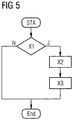
- FIG. 5 shows by way of example individual method steps for carrying out the method for establishing a communication.
- the flowchart is started in state STA.
- a first step X1 for example, the charging station checks whether a physical connection to the electric vehicle has been established, for example with the aid of the controliter SC. If this is not the case, the flowchart is ended in the END state. This path is marked with "N”. Otherwise, the flowchart continues in path "J" and next, the second step X2 is executed.
- the charging station transmits the at least one identifier ID for identifying the communication partners acting in the context of the communication, represented by the first station S1 and the second station S2.
- the second station S2 Upon receipt of the ID tag, the second station S2 starts broadband communication on the outer conductor L1 based on the PLC method or other communication method. This is shown in the flowchart by the third step X3. The flowchart is ended in step END. In an alternative, signaling is further monitored on the signal conductor in step X1. Only after a predefinable operation mode, eg mode 3, is detected, the state diagram in path "J" is continued.
- a predefinable operation mode eg mode 3
- the first station, the second station and the transmission system SYS as well as the individual components and means of these can be implemented and executed in hardware, software or in a combination of software and hardware.
- the implementation of the invention and its components and stations can be carried out by a processor such that the processor reads program code from a memory coupled to it, with the aid of which individual steps of the invention can be executed or the components, such as first and second stations, can be controlled ,
Landscapes
- Engineering & Computer Science (AREA)
- Power Engineering (AREA)
- Mechanical Engineering (AREA)
- Transportation (AREA)
- Sustainable Energy (AREA)
- Life Sciences & Earth Sciences (AREA)
- Sustainable Development (AREA)
- Charge And Discharge Circuits For Batteries Or The Like (AREA)
- Mobile Radio Communication Systems (AREA)
- Electric Propulsion And Braking For Vehicles (AREA)
- Dc Digital Transmission (AREA)
- Communication Control (AREA)
- Cable Transmission Systems, Equalization Of Radio And Reduction Of Echo (AREA)
Applications Claiming Priority (2)
| Application Number | Priority Date | Filing Date | Title |
|---|---|---|---|
| DE102009051401 | 2009-10-30 | ||
| PCT/EP2010/062719 WO2011051021A1 (de) | 2009-10-30 | 2010-08-31 | Verfahren und vorrichtungen zum einrichten einer kommunikation zwischen einer ersten station und einer zweiten station |
Publications (2)
| Publication Number | Publication Date |
|---|---|
| EP2493719A1 EP2493719A1 (de) | 2012-09-05 |
| EP2493719B1 true EP2493719B1 (de) | 2018-08-15 |
Family
ID=43216264
Family Applications (1)
| Application Number | Title | Priority Date | Filing Date |
|---|---|---|---|
| EP10751909.2A Active EP2493719B1 (de) | 2009-10-30 | 2010-08-31 | Verfahren und vorrichtungen zum einrichten einer kommunikation zwischen einer ersten station und einer zweiten station |
Country Status (6)
| Country | Link |
|---|---|
| US (1) | US8873646B2 (zh) |
| EP (1) | EP2493719B1 (zh) |
| JP (1) | JP5623536B2 (zh) |
| KR (1) | KR101552480B1 (zh) |
| CN (1) | CN102596632B (zh) |
| WO (1) | WO2011051021A1 (zh) |
Families Citing this family (11)
| Publication number | Priority date | Publication date | Assignee | Title |
|---|---|---|---|---|
| CN102596632B (zh) | 2009-10-30 | 2015-03-11 | 西门子公司 | 用于在第一站和第二站之间建立通信的方法和设备 |
| DE102011007912A1 (de) | 2011-04-21 | 2012-10-25 | Siemens Aktiengesellschaft | Verfahren zum Aufbau einer IP-basierten Kommunikationsverbindung zwischen einem Elektrofahrzeug und einer Ladesteuereinheit |
| DE102011082897A1 (de) * | 2011-09-16 | 2013-03-21 | Bayerische Motoren Werke Aktiengesellschaft | Ladevorrichtung für ein Fahrzeug |
| DE102011082896A1 (de) * | 2011-09-16 | 2013-03-21 | Bayerische Motoren Werke Aktiengesellschaft | Ladevorrichtung für ein Fahrzeug |
| WO2013097819A1 (zh) | 2011-12-31 | 2013-07-04 | 深圳市比亚迪汽车研发有限公司 | 电动汽车充放电的载波装置及通讯方法与系统 |
| DE102013202234B4 (de) * | 2013-02-12 | 2020-06-18 | Siemens Aktiengesellschaft | Vereinfachte Authentifizierung und Autorisierung für eine Energieübertragung mittels initialer Bindung |
| DE102013221492A1 (de) * | 2013-10-23 | 2015-04-23 | Siemens Aktiengesellschaft | Verfahren und Vorrichtungen zum Erzeugen eines gemeinsamen Geheimnisses |
| JP2015109780A (ja) * | 2013-12-05 | 2015-06-11 | 株式会社デンソー | 車両用電力供給システム |
| DE102015208786A1 (de) * | 2015-05-12 | 2016-11-17 | Bayerische Motoren Werke Aktiengesellschaft | Kommunikationsmodul für den Ladevorgang eines Fahrzeugs |
| US20220055654A1 (en) * | 2020-08-21 | 2022-02-24 | Nuro, Inc. | Methods and Apparatus for User Interactions with Autonomous Vehicles |
| US20220140627A1 (en) * | 2020-10-29 | 2022-05-05 | Google Llc | Geolocation Based Battery Settings |
Family Cites Families (13)
| Publication number | Priority date | Publication date | Assignee | Title |
|---|---|---|---|---|
| JP3717420B2 (ja) * | 2001-04-27 | 2005-11-16 | シャープ株式会社 | モバイルコンセント、電力供給ゲート装置、サーバ装置および電力利用管理システム |
| JP2004222176A (ja) | 2003-01-17 | 2004-08-05 | Sony Corp | 通信システム及び通信方法 |
| JP2007174426A (ja) | 2005-12-22 | 2007-07-05 | Matsushita Electric Works Ltd | 通話装置、および配線システム |
| JP4366382B2 (ja) | 2006-08-02 | 2009-11-18 | 株式会社東海理化電機製作所 | 充電システム |
| JP4487989B2 (ja) | 2006-08-04 | 2010-06-23 | トヨタ自動車株式会社 | 電力システムおよびその電力システムにおいて充電状態を管理する方法 |
| US20080040223A1 (en) * | 2006-08-10 | 2008-02-14 | V2 Green Inc. | Electric Resource Module in a Power Aggregation System for Distributed Electric Resources |
| BRPI0720002A2 (pt) | 2006-12-11 | 2013-12-17 | V2Green Inc | Sistema de agregação de energia para recursos elétricos distribuídos |
| KR101494900B1 (ko) * | 2007-07-25 | 2015-02-24 | 삼성전자주식회사 | 충전 장치 식별을 통한 충전 기능을 갖는 휴대 단말기 및방법 |
| JP2009165301A (ja) | 2008-01-09 | 2009-07-23 | Denso Corp | 車両への電力供給制御装置および電力供給制御装置用のプログラム |
| JP4407753B2 (ja) | 2008-01-15 | 2010-02-03 | トヨタ自動車株式会社 | 電動車両の充電システム |
| IL189332A0 (en) | 2008-02-06 | 2008-11-03 | Zeev Lavi | A system and method for the controlled recharge of batteries in electric powered vehicles |
| US8063604B2 (en) * | 2009-03-13 | 2011-11-22 | Cisco Technology, Inc. | System for associating renewable energy sources and consumers |
| CN102596632B (zh) | 2009-10-30 | 2015-03-11 | 西门子公司 | 用于在第一站和第二站之间建立通信的方法和设备 |
-
2010
- 2010-08-31 CN CN201080048701.2A patent/CN102596632B/zh active Active
- 2010-08-31 EP EP10751909.2A patent/EP2493719B1/de active Active
- 2010-08-31 JP JP2012535695A patent/JP5623536B2/ja active Active
- 2010-08-31 US US13/505,080 patent/US8873646B2/en active Active
- 2010-08-31 WO PCT/EP2010/062719 patent/WO2011051021A1/de active Application Filing
- 2010-08-31 KR KR1020127014061A patent/KR101552480B1/ko active IP Right Grant
Non-Patent Citations (1)
| Title |
|---|
| None * |
Also Published As
| Publication number | Publication date |
|---|---|
| CN102596632A (zh) | 2012-07-18 |
| JP5623536B2 (ja) | 2014-11-12 |
| KR20120093999A (ko) | 2012-08-23 |
| US20120263242A1 (en) | 2012-10-18 |
| WO2011051021A1 (de) | 2011-05-05 |
| EP2493719A1 (de) | 2012-09-05 |
| CN102596632B (zh) | 2015-03-11 |
| KR101552480B1 (ko) | 2015-09-11 |
| JP2013509764A (ja) | 2013-03-14 |
| US8873646B2 (en) | 2014-10-28 |
Similar Documents
| Publication | Publication Date | Title |
|---|---|---|
| EP2493719B1 (de) | Verfahren und vorrichtungen zum einrichten einer kommunikation zwischen einer ersten station und einer zweiten station | |
| EP2678185B1 (de) | Verfahren zum Aufbau einer IP-Basierten Kommunikationsverbindung zwischen einem Elektrofahrzeug und einer Ladesteuereinheit | |
| WO2016184711A1 (de) | Kommunikationsmodul für den ladevorgang eines fahrzeugs | |
| WO2018188819A1 (de) | Steuerungsvorrichtung und verfahren zur steuerung einer ladesäule | |
| EP3507966B1 (de) | Verfahren zum aufbau eines drahtlosen fahrzeug-netzwerks | |
| DE102015206047A1 (de) | Adapter für ein Ladestecksystem | |
| EP3600948A1 (de) | Verfahren zum aufbau einer kommunikationsverbindung, fahrzeug- kommunikationsvorrichtung und ladestations-kommunikationsvorrichtung | |
| WO2011006775A2 (de) | Verfahren zur kommunikation zwischen einem elektrofahrzeug und einer ladestelle zum elektrischen laden zumindest eines energiespeichers des elektrofahrzeugs | |
| EP3609731A1 (de) | Verfahren zur steuerung eines ladevorgangs eines fahrzeugs an einer ladesäule, unter verwendung erstes und zweites berechtigungsnachweises | |
| DE102009026936A1 (de) | Vorrichtung zum Anschluss an ein elektrisches Energieversorgungsnetz und Transportsystem | |
| DE202021104997U1 (de) | Mobiles Ladekabel und Netzanschlussstation | |
| EP3661801B1 (de) | Verfahren zum steuern einer ladestation zum laden von fahrzeugen sowie eine ladestation und ein fahrzeug hierfür | |
| DE102017208323A1 (de) | Robustes intelligentes Ladesystem für Elektrofahrzeuge | |
| EP3628534A1 (de) | Mehrfachladeanschlussvorrichtung für elektrofahrzeuge | |
| DE102019202886A1 (de) | Ladekabel, Ladestecker und Ladeanordnung zum Laden eines Elektrofahrzeuges und Verfahren zum Ausbilden einer elektrischen Verbindung zwischen einer Ladestation und einem Elektrofahrzeug | |
| EP3585643B1 (de) | Ladevorrichtung zum laden eines elektrisch angetriebenen kraftfahrzeugs mit mit zugriff auf ein datennetzwerk und verfahren zum betreiben einer solchen ladevorrichtung | |
| WO2020229088A1 (de) | Ladestation zum laden von elektrofahrzeugen | |
| DE102012020990A1 (de) | Drahtloses Gerät zum Empfangen und Übermitteln eines Audiosignals | |
| EP3651127A1 (de) | Adaptermodul für ein fahrzeug zur aktivierung einer sicherheitsrelevanten funktion des fahrzeuges | |
| WO2012155898A1 (de) | Verfahren und system zur drahtlosen datenübertragung | |
| WO2021160317A1 (de) | Kommunikationssystem für eine ladestation für elektrofahrzeuge, ladestationssystem und ladeinfrastruktur | |
| WO2021009108A1 (de) | Kraftfahrzeug mit einer kommunikationseinrichtung, sowie verfahren zum übertragen eines datenpakets | |
| DE102020103480A1 (de) | Batteriesystem mit mehreren selbstschaltend ausgestalteten Speichereinheiten sowie Kraftfahrzeug mit diesem Batteriesystem und Betriebsversfahren für das Batteriesystem | |
| DE102012002842A1 (de) | Verfahren zum Identifizieren eines mit einer Ladevorrichtung verbundenen Fahrzeugs | |
| DE102018207515A1 (de) | Verfahren und Zugangsvorrichtung zum Bereitstellen eines datentechnischen Zugangs zu einem Fahrzeugnetz eines spurgebundenen Fahrzeugs |
Legal Events
| Date | Code | Title | Description |
|---|---|---|---|
| PUAI | Public reference made under article 153(3) epc to a published international application that has entered the european phase |
Free format text: ORIGINAL CODE: 0009012 |
|
| 17P | Request for examination filed |
Effective date: 20120502 |
|
| AK | Designated contracting states |
Kind code of ref document: A1 Designated state(s): AL AT BE BG CH CY CZ DE DK EE ES FI FR GB GR HR HU IE IS IT LI LT LU LV MC MK MT NL NO PL PT RO SE SI SK SM TR |
|
| DAX | Request for extension of the european patent (deleted) | ||
| RAP1 | Party data changed (applicant data changed or rights of an application transferred) |
Owner name: SIEMENS AKTIENGESELLSCHAFT |
|
| 17Q | First examination report despatched |
Effective date: 20161219 |
|
| RAP1 | Party data changed (applicant data changed or rights of an application transferred) |
Owner name: SIEMENS AKTIENGESELLSCHAFT |
|
| GRAP | Despatch of communication of intention to grant a patent |
Free format text: ORIGINAL CODE: EPIDOSNIGR1 |
|
| INTG | Intention to grant announced |
Effective date: 20180315 |
|
| GRAS | Grant fee paid |
Free format text: ORIGINAL CODE: EPIDOSNIGR3 |
|
| GRAA | (expected) grant |
Free format text: ORIGINAL CODE: 0009210 |
|
| AK | Designated contracting states |
Kind code of ref document: B1 Designated state(s): AL AT BE BG CH CY CZ DE DK EE ES FI FR GB GR HR HU IE IS IT LI LT LU LV MC MK MT NL NO PL PT RO SE SI SK SM TR |
|
| REG | Reference to a national code |
Ref country code: CH Ref legal event code: EP Ref country code: GB Ref legal event code: FG4D Free format text: NOT ENGLISH Ref country code: AT Ref legal event code: REF Ref document number: 1029345 Country of ref document: AT Kind code of ref document: T Effective date: 20180815 |
|
| REG | Reference to a national code |
Ref country code: FR Ref legal event code: PLFP Year of fee payment: 9 |
|
| REG | Reference to a national code |
Ref country code: IE Ref legal event code: FG4D Free format text: LANGUAGE OF EP DOCUMENT: GERMAN |
|
| REG | Reference to a national code |
Ref country code: DE Ref legal event code: R096 Ref document number: 502010015269 Country of ref document: DE |
|
| REG | Reference to a national code |
Ref country code: NL Ref legal event code: MP Effective date: 20180815 |
|
| REG | Reference to a national code |
Ref country code: LT Ref legal event code: MG4D |
|
| REG | Reference to a national code |
Ref country code: DE Ref legal event code: R079 Ref document number: 502010015269 Country of ref document: DE Free format text: PREVIOUS MAIN CLASS: B60L0011180000 Ipc: B60L0050500000 |
|
| PG25 | Lapsed in a contracting state [announced via postgrant information from national office to epo] |
Ref country code: FI Free format text: LAPSE BECAUSE OF FAILURE TO SUBMIT A TRANSLATION OF THE DESCRIPTION OR TO PAY THE FEE WITHIN THE PRESCRIBED TIME-LIMIT Effective date: 20180815 Ref country code: NL Free format text: LAPSE BECAUSE OF FAILURE TO SUBMIT A TRANSLATION OF THE DESCRIPTION OR TO PAY THE FEE WITHIN THE PRESCRIBED TIME-LIMIT Effective date: 20180815 Ref country code: LT Free format text: LAPSE BECAUSE OF FAILURE TO SUBMIT A TRANSLATION OF THE DESCRIPTION OR TO PAY THE FEE WITHIN THE PRESCRIBED TIME-LIMIT Effective date: 20180815 Ref country code: SE Free format text: LAPSE BECAUSE OF FAILURE TO SUBMIT A TRANSLATION OF THE DESCRIPTION OR TO PAY THE FEE WITHIN THE PRESCRIBED TIME-LIMIT Effective date: 20180815 Ref country code: BG Free format text: LAPSE BECAUSE OF FAILURE TO SUBMIT A TRANSLATION OF THE DESCRIPTION OR TO PAY THE FEE WITHIN THE PRESCRIBED TIME-LIMIT Effective date: 20181115 Ref country code: GR Free format text: LAPSE BECAUSE OF FAILURE TO SUBMIT A TRANSLATION OF THE DESCRIPTION OR TO PAY THE FEE WITHIN THE PRESCRIBED TIME-LIMIT Effective date: 20181116 Ref country code: IS Free format text: LAPSE BECAUSE OF FAILURE TO SUBMIT A TRANSLATION OF THE DESCRIPTION OR TO PAY THE FEE WITHIN THE PRESCRIBED TIME-LIMIT Effective date: 20181215 Ref country code: NO Free format text: LAPSE BECAUSE OF FAILURE TO SUBMIT A TRANSLATION OF THE DESCRIPTION OR TO PAY THE FEE WITHIN THE PRESCRIBED TIME-LIMIT Effective date: 20181115 |
|
| PG25 | Lapsed in a contracting state [announced via postgrant information from national office to epo] |
Ref country code: HR Free format text: LAPSE BECAUSE OF FAILURE TO SUBMIT A TRANSLATION OF THE DESCRIPTION OR TO PAY THE FEE WITHIN THE PRESCRIBED TIME-LIMIT Effective date: 20180815 Ref country code: AL Free format text: LAPSE BECAUSE OF FAILURE TO SUBMIT A TRANSLATION OF THE DESCRIPTION OR TO PAY THE FEE WITHIN THE PRESCRIBED TIME-LIMIT Effective date: 20180815 Ref country code: LV Free format text: LAPSE BECAUSE OF FAILURE TO SUBMIT A TRANSLATION OF THE DESCRIPTION OR TO PAY THE FEE WITHIN THE PRESCRIBED TIME-LIMIT Effective date: 20180815 |
|
| REG | Reference to a national code |
Ref country code: CH Ref legal event code: PL |
|
| PG25 | Lapsed in a contracting state [announced via postgrant information from national office to epo] |
Ref country code: CZ Free format text: LAPSE BECAUSE OF FAILURE TO SUBMIT A TRANSLATION OF THE DESCRIPTION OR TO PAY THE FEE WITHIN THE PRESCRIBED TIME-LIMIT Effective date: 20180815 Ref country code: ES Free format text: LAPSE BECAUSE OF FAILURE TO SUBMIT A TRANSLATION OF THE DESCRIPTION OR TO PAY THE FEE WITHIN THE PRESCRIBED TIME-LIMIT Effective date: 20180815 Ref country code: RO Free format text: LAPSE BECAUSE OF FAILURE TO SUBMIT A TRANSLATION OF THE DESCRIPTION OR TO PAY THE FEE WITHIN THE PRESCRIBED TIME-LIMIT Effective date: 20180815 Ref country code: LI Free format text: LAPSE BECAUSE OF NON-PAYMENT OF DUE FEES Effective date: 20180831 Ref country code: CH Free format text: LAPSE BECAUSE OF NON-PAYMENT OF DUE FEES Effective date: 20180831 Ref country code: IT Free format text: LAPSE BECAUSE OF FAILURE TO SUBMIT A TRANSLATION OF THE DESCRIPTION OR TO PAY THE FEE WITHIN THE PRESCRIBED TIME-LIMIT Effective date: 20180815 Ref country code: EE Free format text: LAPSE BECAUSE OF FAILURE TO SUBMIT A TRANSLATION OF THE DESCRIPTION OR TO PAY THE FEE WITHIN THE PRESCRIBED TIME-LIMIT Effective date: 20180815 Ref country code: PL Free format text: LAPSE BECAUSE OF FAILURE TO SUBMIT A TRANSLATION OF THE DESCRIPTION OR TO PAY THE FEE WITHIN THE PRESCRIBED TIME-LIMIT Effective date: 20180815 Ref country code: LU Free format text: LAPSE BECAUSE OF NON-PAYMENT OF DUE FEES Effective date: 20180831 |
|
| REG | Reference to a national code |
Ref country code: BE Ref legal event code: MM Effective date: 20180831 |
|
| REG | Reference to a national code |
Ref country code: DE Ref legal event code: R097 Ref document number: 502010015269 Country of ref document: DE |
|
| PG25 | Lapsed in a contracting state [announced via postgrant information from national office to epo] |
Ref country code: SK Free format text: LAPSE BECAUSE OF FAILURE TO SUBMIT A TRANSLATION OF THE DESCRIPTION OR TO PAY THE FEE WITHIN THE PRESCRIBED TIME-LIMIT Effective date: 20180815 Ref country code: DK Free format text: LAPSE BECAUSE OF FAILURE TO SUBMIT A TRANSLATION OF THE DESCRIPTION OR TO PAY THE FEE WITHIN THE PRESCRIBED TIME-LIMIT Effective date: 20180815 Ref country code: SM Free format text: LAPSE BECAUSE OF FAILURE TO SUBMIT A TRANSLATION OF THE DESCRIPTION OR TO PAY THE FEE WITHIN THE PRESCRIBED TIME-LIMIT Effective date: 20180815 |
|
| PLBE | No opposition filed within time limit |
Free format text: ORIGINAL CODE: 0009261 |
|
| STAA | Information on the status of an ep patent application or granted ep patent |
Free format text: STATUS: NO OPPOSITION FILED WITHIN TIME LIMIT |
|
| PG25 | Lapsed in a contracting state [announced via postgrant information from national office to epo] |
Ref country code: MC Free format text: LAPSE BECAUSE OF FAILURE TO SUBMIT A TRANSLATION OF THE DESCRIPTION OR TO PAY THE FEE WITHIN THE PRESCRIBED TIME-LIMIT Effective date: 20180815 |
|
| 26N | No opposition filed |
Effective date: 20190516 |
|
| PG25 | Lapsed in a contracting state [announced via postgrant information from national office to epo] |
Ref country code: SI Free format text: LAPSE BECAUSE OF FAILURE TO SUBMIT A TRANSLATION OF THE DESCRIPTION OR TO PAY THE FEE WITHIN THE PRESCRIBED TIME-LIMIT Effective date: 20180815 Ref country code: BE Free format text: LAPSE BECAUSE OF NON-PAYMENT OF DUE FEES Effective date: 20180831 |
|
| REG | Reference to a national code |
Ref country code: AT Ref legal event code: MM01 Ref document number: 1029345 Country of ref document: AT Kind code of ref document: T Effective date: 20180831 |
|
| PG25 | Lapsed in a contracting state [announced via postgrant information from national office to epo] |
Ref country code: AT Free format text: LAPSE BECAUSE OF NON-PAYMENT OF DUE FEES Effective date: 20180831 |
|
| PG25 | Lapsed in a contracting state [announced via postgrant information from national office to epo] |
Ref country code: MT Free format text: LAPSE BECAUSE OF FAILURE TO SUBMIT A TRANSLATION OF THE DESCRIPTION OR TO PAY THE FEE WITHIN THE PRESCRIBED TIME-LIMIT Effective date: 20180815 |
|
| PG25 | Lapsed in a contracting state [announced via postgrant information from national office to epo] |
Ref country code: TR Free format text: LAPSE BECAUSE OF FAILURE TO SUBMIT A TRANSLATION OF THE DESCRIPTION OR TO PAY THE FEE WITHIN THE PRESCRIBED TIME-LIMIT Effective date: 20180815 |
|
| PG25 | Lapsed in a contracting state [announced via postgrant information from national office to epo] |
Ref country code: HU Free format text: LAPSE BECAUSE OF FAILURE TO SUBMIT A TRANSLATION OF THE DESCRIPTION OR TO PAY THE FEE WITHIN THE PRESCRIBED TIME-LIMIT; INVALID AB INITIO Effective date: 20100831 Ref country code: PT Free format text: LAPSE BECAUSE OF FAILURE TO SUBMIT A TRANSLATION OF THE DESCRIPTION OR TO PAY THE FEE WITHIN THE PRESCRIBED TIME-LIMIT Effective date: 20180815 |
|
| PG25 | Lapsed in a contracting state [announced via postgrant information from national office to epo] |
Ref country code: IE Free format text: LAPSE BECAUSE OF NON-PAYMENT OF DUE FEES Effective date: 20180831 Ref country code: MK Free format text: LAPSE BECAUSE OF NON-PAYMENT OF DUE FEES Effective date: 20180815 Ref country code: CY Free format text: LAPSE BECAUSE OF FAILURE TO SUBMIT A TRANSLATION OF THE DESCRIPTION OR TO PAY THE FEE WITHIN THE PRESCRIBED TIME-LIMIT Effective date: 20180815 |
|
| PGFP | Annual fee paid to national office [announced via postgrant information from national office to epo] |
Ref country code: GB Payment date: 20230904 Year of fee payment: 14 |
|
| PGFP | Annual fee paid to national office [announced via postgrant information from national office to epo] |
Ref country code: FR Payment date: 20230822 Year of fee payment: 14 |
|
| PGFP | Annual fee paid to national office [announced via postgrant information from national office to epo] |
Ref country code: DE Payment date: 20231019 Year of fee payment: 14 |