EP2493418B1 - Bioerodible wraps and uses therefor - Google Patents
Bioerodible wraps and uses therefor Download PDFInfo
- Publication number
- EP2493418B1 EP2493418B1 EP10828927.3A EP10828927A EP2493418B1 EP 2493418 B1 EP2493418 B1 EP 2493418B1 EP 10828927 A EP10828927 A EP 10828927A EP 2493418 B1 EP2493418 B1 EP 2493418B1
- Authority
- EP
- European Patent Office
- Prior art keywords
- scaffold
- vein
- polymer
- matrix
- fiber matrix
- Prior art date
- Legal status (The legal status is an assumption and is not a legal conclusion. Google has not performed a legal analysis and makes no representation as to the accuracy of the status listed.)
- Active
Links
- 229920000642 polymer Polymers 0.000 claims description 166
- 239000011159 matrix material Substances 0.000 claims description 161
- 239000000835 fiber Substances 0.000 claims description 141
- 239000000463 material Substances 0.000 claims description 36
- 230000008021 deposition Effects 0.000 claims description 29
- 239000010410 layer Substances 0.000 claims description 24
- 238000010276 construction Methods 0.000 claims description 18
- 239000002904 solvent Substances 0.000 claims description 13
- 238000006065 biodegradation reaction Methods 0.000 claims description 8
- 229910001220 stainless steel Inorganic materials 0.000 claims description 7
- 239000010935 stainless steel Substances 0.000 claims description 7
- 230000007246 mechanism Effects 0.000 claims description 6
- 239000002131 composite material Substances 0.000 claims description 5
- 239000007943 implant Substances 0.000 claims description 5
- 230000008093 supporting effect Effects 0.000 claims description 5
- 239000002356 single layer Substances 0.000 claims description 4
- 229910001000 nickel titanium Inorganic materials 0.000 claims description 3
- HLXZNVUGXRDIFK-UHFFFAOYSA-N nickel titanium Chemical compound [Ti].[Ti].[Ti].[Ti].[Ti].[Ti].[Ti].[Ti].[Ti].[Ti].[Ti].[Ni].[Ni].[Ni].[Ni].[Ni].[Ni].[Ni].[Ni].[Ni].[Ni].[Ni].[Ni].[Ni].[Ni] HLXZNVUGXRDIFK-UHFFFAOYSA-N 0.000 claims description 3
- 229920003023 plastic Polymers 0.000 claims description 3
- 239000004033 plastic Substances 0.000 claims description 3
- 238000004873 anchoring Methods 0.000 claims description 2
- 210000003462 vein Anatomy 0.000 description 180
- 210000004027 cell Anatomy 0.000 description 121
- 238000000034 method Methods 0.000 description 121
- 210000001519 tissue Anatomy 0.000 description 111
- 210000000329 smooth muscle myocyte Anatomy 0.000 description 89
- 238000002474 experimental method Methods 0.000 description 71
- 230000010412 perfusion Effects 0.000 description 61
- 230000008569 process Effects 0.000 description 54
- 238000001523 electrospinning Methods 0.000 description 48
- 230000001965 increasing effect Effects 0.000 description 42
- 210000003752 saphenous vein Anatomy 0.000 description 42
- 206010020718 hyperplasia Diseases 0.000 description 40
- -1 polytetrafluoroethylene Polymers 0.000 description 38
- 108010035532 Collagen Proteins 0.000 description 37
- 102000008186 Collagen Human genes 0.000 description 37
- 229920001436 collagen Polymers 0.000 description 37
- 238000004519 manufacturing process Methods 0.000 description 37
- 230000004044 response Effects 0.000 description 36
- 230000002792 vascular Effects 0.000 description 34
- 230000035755 proliferation Effects 0.000 description 32
- 239000000243 solution Substances 0.000 description 32
- 241000282414 Homo sapiens Species 0.000 description 31
- 239000000203 mixture Substances 0.000 description 29
- 102000010834 Extracellular Matrix Proteins Human genes 0.000 description 28
- 108010037362 Extracellular Matrix Proteins Proteins 0.000 description 28
- 238000004458 analytical method Methods 0.000 description 27
- 210000002744 extracellular matrix Anatomy 0.000 description 27
- 239000003814 drug Substances 0.000 description 26
- 230000000694 effects Effects 0.000 description 26
- 108090000623 proteins and genes Proteins 0.000 description 25
- 230000002829 reductive effect Effects 0.000 description 25
- 230000006907 apoptotic process Effects 0.000 description 24
- 238000005259 measurement Methods 0.000 description 24
- 238000001356 surgical procedure Methods 0.000 description 24
- 238000013508 migration Methods 0.000 description 23
- 230000000541 pulsatile effect Effects 0.000 description 23
- 241001465754 Metazoa Species 0.000 description 22
- 238000013459 approach Methods 0.000 description 22
- IAZDPXIOMUYVGZ-UHFFFAOYSA-N Dimethylsulphoxide Chemical compound CS(C)=O IAZDPXIOMUYVGZ-UHFFFAOYSA-N 0.000 description 21
- 102000016942 Elastin Human genes 0.000 description 21
- 108010014258 Elastin Proteins 0.000 description 21
- 238000000151 deposition Methods 0.000 description 21
- 230000014509 gene expression Effects 0.000 description 21
- 238000010186 staining Methods 0.000 description 21
- 208000034827 Neointima Diseases 0.000 description 20
- 229920002549 elastin Polymers 0.000 description 20
- 230000000004 hemodynamic effect Effects 0.000 description 20
- 102000004169 proteins and genes Human genes 0.000 description 20
- 230000006870 function Effects 0.000 description 19
- 238000001727 in vivo Methods 0.000 description 19
- 230000000670 limiting effect Effects 0.000 description 19
- 102100020944 Integrin-linked protein kinase Human genes 0.000 description 18
- 230000001413 cellular effect Effects 0.000 description 18
- 210000001650 focal adhesion Anatomy 0.000 description 18
- 108010059517 integrin-linked kinase Proteins 0.000 description 18
- 230000005012 migration Effects 0.000 description 18
- 235000018102 proteins Nutrition 0.000 description 17
- 235000013877 carbamide Nutrition 0.000 description 16
- 238000006731 degradation reaction Methods 0.000 description 16
- 229940079593 drug Drugs 0.000 description 16
- 230000035899 viability Effects 0.000 description 16
- XSQUKJJJFZCRTK-UHFFFAOYSA-N Urea Chemical compound NC(N)=O XSQUKJJJFZCRTK-UHFFFAOYSA-N 0.000 description 15
- 239000004202 carbamide Substances 0.000 description 15
- 230000015556 catabolic process Effects 0.000 description 15
- 238000011161 development Methods 0.000 description 15
- 230000018109 developmental process Effects 0.000 description 15
- 230000002390 hyperplastic effect Effects 0.000 description 15
- 230000008692 neointimal formation Effects 0.000 description 15
- 229920001982 poly(ester urethane) Polymers 0.000 description 15
- 102100040684 Fermitin family homolog 2 Human genes 0.000 description 14
- 101000892677 Homo sapiens Fermitin family homolog 2 Proteins 0.000 description 14
- 239000000178 monomer Substances 0.000 description 14
- KIDHWZJUCRJVML-UHFFFAOYSA-N putrescine Chemical compound NCCCCN KIDHWZJUCRJVML-UHFFFAOYSA-N 0.000 description 14
- UCTWMZQNUQWSLP-VIFPVBQESA-N (R)-adrenaline Chemical compound CNC[C@H](O)C1=CC=C(O)C(O)=C1 UCTWMZQNUQWSLP-VIFPVBQESA-N 0.000 description 13
- 229930182837 (R)-adrenaline Natural products 0.000 description 13
- MWUXSHHQAYIFBG-UHFFFAOYSA-N Nitric oxide Chemical compound O=[N] MWUXSHHQAYIFBG-UHFFFAOYSA-N 0.000 description 13
- 230000004872 arterial blood pressure Effects 0.000 description 13
- 229920002988 biodegradable polymer Polymers 0.000 description 13
- 239000004621 biodegradable polymer Substances 0.000 description 13
- 230000004663 cell proliferation Effects 0.000 description 13
- 230000004087 circulation Effects 0.000 description 13
- 230000007423 decrease Effects 0.000 description 13
- 229960005139 epinephrine Drugs 0.000 description 13
- 238000003364 immunohistochemistry Methods 0.000 description 13
- 102000007469 Actins Human genes 0.000 description 12
- 108010085238 Actins Proteins 0.000 description 12
- 108050006400 Cyclin Proteins 0.000 description 12
- AOJJSUZBOXZQNB-TZSSRYMLSA-N Doxorubicin Chemical compound O([C@H]1C[C@@](O)(CC=2C(O)=C3C(=O)C=4C=CC=C(C=4C(=O)C3=C(O)C=21)OC)C(=O)CO)[C@H]1C[C@H](N)[C@H](O)[C@H](C)O1 AOJJSUZBOXZQNB-TZSSRYMLSA-N 0.000 description 12
- 102000002274 Matrix Metalloproteinases Human genes 0.000 description 12
- 108010000684 Matrix Metalloproteinases Proteins 0.000 description 12
- 102000009339 Proliferating Cell Nuclear Antigen Human genes 0.000 description 12
- 230000006378 damage Effects 0.000 description 12
- 239000012530 fluid Substances 0.000 description 12
- 210000002288 golgi apparatus Anatomy 0.000 description 12
- 239000003102 growth factor Substances 0.000 description 12
- 238000000338 in vitro Methods 0.000 description 12
- 238000007634 remodeling Methods 0.000 description 12
- 238000007631 vascular surgery Methods 0.000 description 12
- 230000004075 alteration Effects 0.000 description 11
- 210000001367 artery Anatomy 0.000 description 11
- 230000015572 biosynthetic process Effects 0.000 description 11
- XRKMNJXYOFSTBE-UHFFFAOYSA-N disodium;iron(4+);nitroxyl anion;pentacyanide;dihydrate Chemical compound O.O.[Na+].[Na+].[Fe+4].N#[C-].N#[C-].N#[C-].N#[C-].N#[C-].O=[N-] XRKMNJXYOFSTBE-UHFFFAOYSA-N 0.000 description 11
- 230000009467 reduction Effects 0.000 description 11
- 230000001105 regulatory effect Effects 0.000 description 11
- QFJCIRLUMZQUOT-HPLJOQBZSA-N sirolimus Chemical compound C1C[C@@H](O)[C@H](OC)C[C@@H]1C[C@@H](C)[C@H]1OC(=O)[C@@H]2CCCCN2C(=O)C(=O)[C@](O)(O2)[C@H](C)CC[C@H]2C[C@H](OC)/C(C)=C/C=C/C=C/[C@@H](C)C[C@@H](C)C(=O)[C@H](OC)[C@H](O)/C(C)=C/[C@@H](C)C(=O)C1 QFJCIRLUMZQUOT-HPLJOQBZSA-N 0.000 description 11
- 229940083618 sodium nitroprusside Drugs 0.000 description 11
- 230000003068 static effect Effects 0.000 description 11
- RCINICONZNJXQF-MZXODVADSA-N taxol Chemical compound O([C@@H]1[C@@]2(C[C@@H](C(C)=C(C2(C)C)[C@H](C([C@]2(C)[C@@H](O)C[C@H]3OC[C@]3([C@H]21)OC(C)=O)=O)OC(=O)C)OC(=O)[C@H](O)[C@@H](NC(=O)C=1C=CC=CC=1)C=1C=CC=CC=1)O)C(=O)C1=CC=CC=C1 RCINICONZNJXQF-MZXODVADSA-N 0.000 description 11
- 229940124597 therapeutic agent Drugs 0.000 description 11
- 102000000424 Matrix Metalloproteinase 2 Human genes 0.000 description 10
- 108010016165 Matrix Metalloproteinase 2 Proteins 0.000 description 10
- 206010028851 Necrosis Diseases 0.000 description 10
- 229930012538 Paclitaxel Natural products 0.000 description 10
- 241000700159 Rattus Species 0.000 description 10
- 239000003795 chemical substances by application Substances 0.000 description 10
- 230000003750 conditioning effect Effects 0.000 description 10
- 125000004122 cyclic group Chemical group 0.000 description 10
- 238000007787 electrohydrodynamic spraying Methods 0.000 description 10
- 238000011065 in-situ storage Methods 0.000 description 10
- 230000007774 longterm Effects 0.000 description 10
- 230000001404 mediated effect Effects 0.000 description 10
- 230000017074 necrotic cell death Effects 0.000 description 10
- 210000000056 organ Anatomy 0.000 description 10
- 229960001592 paclitaxel Drugs 0.000 description 10
- 230000002062 proliferating effect Effects 0.000 description 10
- 238000004626 scanning electron microscopy Methods 0.000 description 10
- 238000005507 spraying Methods 0.000 description 10
- 230000008719 thickening Effects 0.000 description 10
- 230000001457 vasomotor Effects 0.000 description 10
- BYEAHWXPCBROCE-UHFFFAOYSA-N 1,1,1,3,3,3-hexafluoropropan-2-ol Chemical compound FC(F)(F)C(O)C(F)(F)F BYEAHWXPCBROCE-UHFFFAOYSA-N 0.000 description 9
- 108090000379 Fibroblast growth factor 2 Proteins 0.000 description 9
- 102000003974 Fibroblast growth factor 2 Human genes 0.000 description 9
- 108090000723 Insulin-Like Growth Factor I Proteins 0.000 description 9
- 206010072810 Vascular wall hypertrophy Diseases 0.000 description 9
- 208000027418 Wounds and injury Diseases 0.000 description 9
- 230000001154 acute effect Effects 0.000 description 9
- 230000003110 anti-inflammatory effect Effects 0.000 description 9
- 230000033228 biological regulation Effects 0.000 description 9
- 210000000038 chest Anatomy 0.000 description 9
- 238000011835 investigation Methods 0.000 description 9
- 230000002265 prevention Effects 0.000 description 9
- 239000000523 sample Substances 0.000 description 9
- YNDXUCZADRHECN-JNQJZLCISA-N triamcinolone acetonide Chemical compound C1CC2=CC(=O)C=C[C@]2(C)[C@]2(F)[C@@H]1[C@@H]1C[C@H]3OC(C)(C)O[C@@]3(C(=O)CO)[C@@]1(C)C[C@@H]2O YNDXUCZADRHECN-JNQJZLCISA-N 0.000 description 9
- 210000004509 vascular smooth muscle cell Anatomy 0.000 description 9
- OVBFMUAFNIIQAL-UHFFFAOYSA-N 1,4-diisocyanatobutane Chemical compound O=C=NCCCCN=C=O OVBFMUAFNIIQAL-UHFFFAOYSA-N 0.000 description 8
- 239000005552 B01AC04 - Clopidogrel Substances 0.000 description 8
- LFQSCWFLJHTTHZ-UHFFFAOYSA-N Ethanol Chemical compound CCO LFQSCWFLJHTTHZ-UHFFFAOYSA-N 0.000 description 8
- WZUVPPKBWHMQCE-UHFFFAOYSA-N Haematoxylin Chemical compound C12=CC(O)=C(O)C=C2CC2(O)C1C1=CC=C(O)C(O)=C1OC2 WZUVPPKBWHMQCE-UHFFFAOYSA-N 0.000 description 8
- 102000007000 Tenascin Human genes 0.000 description 8
- 108010008125 Tenascin Proteins 0.000 description 8
- 102000004887 Transforming Growth Factor beta Human genes 0.000 description 8
- 108090001012 Transforming Growth Factor beta Proteins 0.000 description 8
- 230000004913 activation Effects 0.000 description 8
- 210000004204 blood vessel Anatomy 0.000 description 8
- 230000008859 change Effects 0.000 description 8
- GKTWGGQPFAXNFI-HNNXBMFYSA-N clopidogrel Chemical compound C1([C@H](N2CC=3C=CSC=3CC2)C(=O)OC)=CC=CC=C1Cl GKTWGGQPFAXNFI-HNNXBMFYSA-N 0.000 description 8
- 210000004292 cytoskeleton Anatomy 0.000 description 8
- 238000011156 evaluation Methods 0.000 description 8
- 208000014674 injury Diseases 0.000 description 8
- 229920005594 polymer fiber Polymers 0.000 description 8
- ZAHRKKWIAAJSAO-UHFFFAOYSA-N rapamycin Natural products COCC(O)C(=C/C(C)C(=O)CC(OC(=O)C1CCCCN1C(=O)C(=O)C2(O)OC(CC(OC)C(=CC=CC=CC(C)CC(C)C(=O)C)C)CCC2C)C(C)CC3CCC(O)C(C3)OC)C ZAHRKKWIAAJSAO-UHFFFAOYSA-N 0.000 description 8
- 229960002930 sirolimus Drugs 0.000 description 8
- 230000015590 smooth muscle cell migration Effects 0.000 description 8
- 102000004127 Cytokines Human genes 0.000 description 7
- 108090000695 Cytokines Proteins 0.000 description 7
- 108010010803 Gelatin Proteins 0.000 description 7
- 108010038512 Platelet-Derived Growth Factor Proteins 0.000 description 7
- 102000010780 Platelet-Derived Growth Factor Human genes 0.000 description 7
- RYMZZMVNJRMUDD-UHFFFAOYSA-N SJ000286063 Natural products C12C(OC(=O)C(C)(C)CC)CC(C)C=C2C=CC(C)C1CCC1CC(O)CC(=O)O1 RYMZZMVNJRMUDD-UHFFFAOYSA-N 0.000 description 7
- 102100037599 SPARC Human genes 0.000 description 7
- 101710100111 SPARC Proteins 0.000 description 7
- 239000013543 active substance Substances 0.000 description 7
- 238000002583 angiography Methods 0.000 description 7
- 238000003556 assay Methods 0.000 description 7
- 230000009286 beneficial effect Effects 0.000 description 7
- 229920013641 bioerodible polymer Polymers 0.000 description 7
- LOKCTEFSRHRXRJ-UHFFFAOYSA-I dipotassium trisodium dihydrogen phosphate hydrogen phosphate dichloride Chemical compound P(=O)(O)(O)[O-].[K+].P(=O)(O)([O-])[O-].[Na+].[Na+].[Cl-].[K+].[Cl-].[Na+] LOKCTEFSRHRXRJ-UHFFFAOYSA-I 0.000 description 7
- 210000002889 endothelial cell Anatomy 0.000 description 7
- 150000002148 esters Chemical class 0.000 description 7
- 229920000159 gelatin Polymers 0.000 description 7
- 239000008273 gelatin Substances 0.000 description 7
- 235000019322 gelatine Nutrition 0.000 description 7
- 235000011852 gelatine desserts Nutrition 0.000 description 7
- 238000002513 implantation Methods 0.000 description 7
- 210000001349 mammary artery Anatomy 0.000 description 7
- 230000004048 modification Effects 0.000 description 7
- 238000012986 modification Methods 0.000 description 7
- 239000002953 phosphate buffered saline Substances 0.000 description 7
- 230000035479 physiological effects, processes and functions Effects 0.000 description 7
- 229920001610 polycaprolactone Polymers 0.000 description 7
- 239000002243 precursor Substances 0.000 description 7
- 238000011160 research Methods 0.000 description 7
- 238000001878 scanning electron micrograph Methods 0.000 description 7
- 229960002855 simvastatin Drugs 0.000 description 7
- RYMZZMVNJRMUDD-HGQWONQESA-N simvastatin Chemical compound C([C@H]1[C@@H](C)C=CC2=C[C@H](C)C[C@@H]([C@H]12)OC(=O)C(C)(C)CC)C[C@@H]1C[C@@H](O)CC(=O)O1 RYMZZMVNJRMUDD-HGQWONQESA-N 0.000 description 7
- 210000002460 smooth muscle Anatomy 0.000 description 7
- 210000000130 stem cell Anatomy 0.000 description 7
- IAKHMKGGTNLKSZ-INIZCTEOSA-N (S)-colchicine Chemical compound C1([C@@H](NC(C)=O)CC2)=CC(=O)C(OC)=CC=C1C1=C2C=C(OC)C(OC)=C1OC IAKHMKGGTNLKSZ-INIZCTEOSA-N 0.000 description 6
- CMSMOCZEIVJLDB-UHFFFAOYSA-N Cyclophosphamide Chemical compound ClCCN(CCCl)P1(=O)NCCCO1 CMSMOCZEIVJLDB-UHFFFAOYSA-N 0.000 description 6
- YMWUJEATGCHHMB-UHFFFAOYSA-N Dichloromethane Chemical compound ClCCl YMWUJEATGCHHMB-UHFFFAOYSA-N 0.000 description 6
- ULGZDMOVFRHVEP-RWJQBGPGSA-N Erythromycin Chemical compound O([C@@H]1[C@@H](C)C(=O)O[C@@H]([C@@]([C@H](O)[C@@H](C)C(=O)[C@H](C)C[C@@](C)(O)[C@H](O[C@H]2[C@@H]([C@H](C[C@@H](C)O2)N(C)C)O)[C@H]1C)(C)O)CC)[C@H]1C[C@@](C)(OC)[C@@H](O)[C@H](C)O1 ULGZDMOVFRHVEP-RWJQBGPGSA-N 0.000 description 6
- JOYRKODLDBILNP-UHFFFAOYSA-N Ethyl urethane Chemical compound CCOC(N)=O JOYRKODLDBILNP-UHFFFAOYSA-N 0.000 description 6
- 108090000386 Fibroblast Growth Factor 1 Proteins 0.000 description 6
- 102000003971 Fibroblast Growth Factor 1 Human genes 0.000 description 6
- GHASVSINZRGABV-UHFFFAOYSA-N Fluorouracil Chemical compound FC1=CNC(=O)NC1=O GHASVSINZRGABV-UHFFFAOYSA-N 0.000 description 6
- 102000003745 Hepatocyte Growth Factor Human genes 0.000 description 6
- 108090000100 Hepatocyte Growth Factor Proteins 0.000 description 6
- FBOZXECLQNJBKD-ZDUSSCGKSA-N L-methotrexate Chemical compound C=1N=C2N=C(N)N=C(N)C2=NC=1CN(C)C1=CC=C(C(=O)N[C@@H](CCC(O)=O)C(O)=O)C=C1 FBOZXECLQNJBKD-ZDUSSCGKSA-N 0.000 description 6
- 108010015302 Matrix metalloproteinase-9 Proteins 0.000 description 6
- 102100030412 Matrix metalloproteinase-9 Human genes 0.000 description 6
- OKKJLVBELUTLKV-UHFFFAOYSA-N Methanol Chemical compound OC OKKJLVBELUTLKV-UHFFFAOYSA-N 0.000 description 6
- 239000005700 Putrescine Substances 0.000 description 6
- 102000013275 Somatomedins Human genes 0.000 description 6
- 102100036034 Thrombospondin-1 Human genes 0.000 description 6
- 108010073929 Vascular Endothelial Growth Factor A Proteins 0.000 description 6
- 102000005789 Vascular Endothelial Growth Factors Human genes 0.000 description 6
- 108010019530 Vascular Endothelial Growth Factors Proteins 0.000 description 6
- 239000003242 anti bacterial agent Substances 0.000 description 6
- QVGXLLKOCUKJST-UHFFFAOYSA-N atomic oxygen Chemical compound [O] QVGXLLKOCUKJST-UHFFFAOYSA-N 0.000 description 6
- 230000003115 biocidal effect Effects 0.000 description 6
- 239000012620 biological material Substances 0.000 description 6
- 210000001715 carotid artery Anatomy 0.000 description 6
- 230000030833 cell death Effects 0.000 description 6
- 230000012292 cell migration Effects 0.000 description 6
- 238000006243 chemical reaction Methods 0.000 description 6
- MYSWGUAQZAJSOK-UHFFFAOYSA-N ciprofloxacin Chemical compound C12=CC(N3CCNCC3)=C(F)C=C2C(=O)C(C(=O)O)=CN1C1CC1 MYSWGUAQZAJSOK-UHFFFAOYSA-N 0.000 description 6
- 229960004397 cyclophosphamide Drugs 0.000 description 6
- 230000003247 decreasing effect Effects 0.000 description 6
- 229960003957 dexamethasone Drugs 0.000 description 6
- UREBDLICKHMUKA-CXSFZGCWSA-N dexamethasone Chemical compound C1CC2=CC(=O)C=C[C@]2(C)[C@]2(F)[C@@H]1[C@@H]1C[C@@H](C)[C@@](C(=O)CO)(O)[C@@]1(C)C[C@@H]2O UREBDLICKHMUKA-CXSFZGCWSA-N 0.000 description 6
- 229960004679 doxorubicin Drugs 0.000 description 6
- 230000005684 electric field Effects 0.000 description 6
- 230000003511 endothelial effect Effects 0.000 description 6
- AEUTYOVWOVBAKS-UWVGGRQHSA-N ethambutol Chemical compound CC[C@@H](CO)NCCN[C@@H](CC)CO AEUTYOVWOVBAKS-UWVGGRQHSA-N 0.000 description 6
- 229960002949 fluorouracil Drugs 0.000 description 6
- 238000007490 hematoxylin and eosin (H&E) staining Methods 0.000 description 6
- JYGXADMDTFJGBT-VWUMJDOOSA-N hydrocortisone Chemical compound O=C1CC[C@]2(C)[C@H]3[C@@H](O)C[C@](C)([C@@](CC4)(O)C(=O)CO)[C@@H]4[C@@H]3CCC2=C1 JYGXADMDTFJGBT-VWUMJDOOSA-N 0.000 description 6
- CGIGDMFJXJATDK-UHFFFAOYSA-N indomethacin Chemical compound CC1=C(CC(O)=O)C2=CC(OC)=CC=C2N1C(=O)C1=CC=C(Cl)C=C1 CGIGDMFJXJATDK-UHFFFAOYSA-N 0.000 description 6
- 210000004731 jugular vein Anatomy 0.000 description 6
- 229910052751 metal Inorganic materials 0.000 description 6
- 239000002184 metal Substances 0.000 description 6
- 229960000485 methotrexate Drugs 0.000 description 6
- 229920005615 natural polymer Polymers 0.000 description 6
- 229940021182 non-steroidal anti-inflammatory drug Drugs 0.000 description 6
- 239000001301 oxygen Substances 0.000 description 6
- 229910052760 oxygen Inorganic materials 0.000 description 6
- NDTYTMIUWGWIMO-UHFFFAOYSA-N perillyl alcohol Chemical compound CC(=C)C1CCC(CO)=CC1 NDTYTMIUWGWIMO-UHFFFAOYSA-N 0.000 description 6
- ZJAOAACCNHFJAH-UHFFFAOYSA-N phosphonoformic acid Chemical compound OC(=O)P(O)(O)=O ZJAOAACCNHFJAH-UHFFFAOYSA-N 0.000 description 6
- 239000011148 porous material Substances 0.000 description 6
- 238000012545 processing Methods 0.000 description 6
- 229960000581 salicylamide Drugs 0.000 description 6
- YGSDEFSMJLZEOE-UHFFFAOYSA-N salicylic acid Chemical compound OC(=O)C1=CC=CC=C1O YGSDEFSMJLZEOE-UHFFFAOYSA-N 0.000 description 6
- 230000011664 signaling Effects 0.000 description 6
- UCSJYZPVAKXKNQ-HZYVHMACSA-N streptomycin Chemical compound CN[C@H]1[C@H](O)[C@@H](O)[C@H](CO)O[C@H]1O[C@@H]1[C@](C=O)(O)[C@H](C)O[C@H]1O[C@@H]1[C@@H](NC(N)=N)[C@H](O)[C@@H](NC(N)=N)[C@H](O)[C@H]1O UCSJYZPVAKXKNQ-HZYVHMACSA-N 0.000 description 6
- 239000000126 substance Substances 0.000 description 6
- 238000012360 testing method Methods 0.000 description 6
- 230000014616 translation Effects 0.000 description 6
- 230000024883 vasodilation Effects 0.000 description 6
- PJVWKTKQMONHTI-UHFFFAOYSA-N warfarin Chemical compound OC=1C2=CC=CC=C2OC(=O)C=1C(CC(=O)C)C1=CC=CC=C1 PJVWKTKQMONHTI-UHFFFAOYSA-N 0.000 description 6
- BSYNRYMUTXBXSQ-UHFFFAOYSA-N Aspirin Chemical compound CC(=O)OC1=CC=CC=C1C(O)=O BSYNRYMUTXBXSQ-UHFFFAOYSA-N 0.000 description 5
- 108091003079 Bovine Serum Albumin Proteins 0.000 description 5
- 102000014914 Carrier Proteins Human genes 0.000 description 5
- GNWUOVJNSFPWDD-XMZRARIVSA-M Cefoxitin sodium Chemical compound [Na+].N([C@]1(OC)C(N2C(=C(COC(N)=O)CS[C@@H]21)C([O-])=O)=O)C(=O)CC1=CC=CS1 GNWUOVJNSFPWDD-XMZRARIVSA-M 0.000 description 5
- 108060002900 Filamin Proteins 0.000 description 5
- 102000013366 Filamin Human genes 0.000 description 5
- 102100037564 Filamin-binding LIM protein 1 Human genes 0.000 description 5
- 229940121710 HMGCoA reductase inhibitor Drugs 0.000 description 5
- HTTJABKRGRZYRN-UHFFFAOYSA-N Heparin Chemical compound OC1C(NC(=O)C)C(O)OC(COS(O)(=O)=O)C1OC1C(OS(O)(=O)=O)C(O)C(OC2C(C(OS(O)(=O)=O)C(OC3C(C(O)C(O)C(O3)C(O)=O)OS(O)(=O)=O)C(CO)O2)NS(O)(=O)=O)C(C(O)=O)O1 HTTJABKRGRZYRN-UHFFFAOYSA-N 0.000 description 5
- 101001028052 Homo sapiens Filamin-binding LIM protein 1 Proteins 0.000 description 5
- 102000000521 Immunophilins Human genes 0.000 description 5
- 108010016648 Immunophilins Proteins 0.000 description 5
- 102000014150 Interferons Human genes 0.000 description 5
- 108010050904 Interferons Proteins 0.000 description 5
- 206010029113 Neovascularisation Diseases 0.000 description 5
- 241000283973 Oryctolagus cuniculus Species 0.000 description 5
- 208000031481 Pathologic Constriction Diseases 0.000 description 5
- 229920000954 Polyglycolide Polymers 0.000 description 5
- YIQKLZYTHXTDDT-UHFFFAOYSA-H Sirius red F3B Chemical compound C1=CC(=CC=C1N=NC2=CC(=C(C=C2)N=NC3=C(C=C4C=C(C=CC4=C3[O-])NC(=O)NC5=CC6=CC(=C(C(=C6C=C5)[O-])N=NC7=C(C=C(C=C7)N=NC8=CC=C(C=C8)S(=O)(=O)[O-])S(=O)(=O)[O-])S(=O)(=O)O)S(=O)(=O)O)S(=O)(=O)[O-])S(=O)(=O)[O-].[Na+].[Na+].[Na+].[Na+].[Na+].[Na+] YIQKLZYTHXTDDT-UHFFFAOYSA-H 0.000 description 5
- 241000282887 Suidae Species 0.000 description 5
- 229940123237 Taxane Drugs 0.000 description 5
- 102100040247 Tumor necrosis factor Human genes 0.000 description 5
- 229960001138 acetylsalicylic acid Drugs 0.000 description 5
- 230000003872 anastomosis Effects 0.000 description 5
- 210000003484 anatomy Anatomy 0.000 description 5
- 230000001640 apoptogenic effect Effects 0.000 description 5
- 230000027455 binding Effects 0.000 description 5
- 108091008324 binding proteins Proteins 0.000 description 5
- 230000008238 biochemical pathway Effects 0.000 description 5
- 230000000747 cardiac effect Effects 0.000 description 5
- 229960002682 cefoxitin Drugs 0.000 description 5
- 210000004351 coronary vessel Anatomy 0.000 description 5
- 230000010339 dilation Effects 0.000 description 5
- 229920001971 elastomer Polymers 0.000 description 5
- 239000000806 elastomer Substances 0.000 description 5
- 210000003038 endothelium Anatomy 0.000 description 5
- 238000005516 engineering process Methods 0.000 description 5
- 229920000295 expanded polytetrafluoroethylene Polymers 0.000 description 5
- 239000012091 fetal bovine serum Substances 0.000 description 5
- 239000003862 glucocorticoid Substances 0.000 description 5
- 238000003306 harvesting Methods 0.000 description 5
- 229960002897 heparin Drugs 0.000 description 5
- 229920000669 heparin Polymers 0.000 description 5
- 230000006698 induction Effects 0.000 description 5
- 230000004807 localization Effects 0.000 description 5
- 239000002840 nitric oxide donor Substances 0.000 description 5
- 235000015097 nutrients Nutrition 0.000 description 5
- 210000003101 oviduct Anatomy 0.000 description 5
- 229940020573 plavix Drugs 0.000 description 5
- 229920000747 poly(lactic acid) Polymers 0.000 description 5
- 229920002635 polyurethane Polymers 0.000 description 5
- 239000004814 polyurethane Substances 0.000 description 5
- 239000007921 spray Substances 0.000 description 5
- 230000036262 stenosis Effects 0.000 description 5
- 208000037804 stenosis Diseases 0.000 description 5
- 230000000638 stimulation Effects 0.000 description 5
- 239000000725 suspension Substances 0.000 description 5
- ZRKFYGHZFMAOKI-QMGMOQQFSA-N tgfbeta Chemical compound C([C@H](NC(=O)[C@H](C(C)C)NC(=O)CNC(=O)[C@H](CCC(O)=O)NC(=O)[C@H](CCCNC(N)=N)NC(=O)[C@H](CC(N)=O)NC(=O)[C@H](CC(C)C)NC(=O)[C@H]([C@@H](C)O)NC(=O)[C@H](CCC(O)=O)NC(=O)[C@H]([C@@H](C)O)NC(=O)[C@H](CC(C)C)NC(=O)CNC(=O)[C@H](C)NC(=O)[C@H](CO)NC(=O)[C@H](CCC(N)=O)NC(=O)[C@@H](NC(=O)[C@H](C)NC(=O)[C@H](C)NC(=O)[C@@H](NC(=O)[C@H](CC(C)C)NC(=O)[C@@H](N)CCSC)C(C)C)[C@@H](C)CC)C(=O)N[C@@H]([C@@H](C)O)C(=O)N[C@@H](C(C)C)C(=O)N[C@@H](CC=1C=CC=CC=1)C(=O)N[C@@H](C)C(=O)N1[C@@H](CCC1)C(=O)N[C@@H]([C@@H](C)O)C(=O)N[C@@H](CC(N)=O)C(=O)N[C@@H](CCC(O)=O)C(=O)N[C@@H](C)C(=O)N[C@@H](CC=1C=CC=CC=1)C(=O)N[C@@H](CCCNC(N)=N)C(=O)N[C@@H](C)C(=O)N[C@@H](CC(C)C)C(=O)N1[C@@H](CCC1)C(=O)N1[C@@H](CCC1)C(=O)N[C@@H](CCCNC(N)=N)C(=O)N[C@@H](CCC(O)=O)C(=O)N[C@@H](CCCNC(N)=N)C(=O)N[C@@H](CO)C(=O)N[C@@H](CCCNC(N)=N)C(=O)N[C@@H](CC(C)C)C(=O)N[C@@H](CC(C)C)C(O)=O)C1=CC=C(O)C=C1 ZRKFYGHZFMAOKI-QMGMOQQFSA-N 0.000 description 5
- 238000013519 translation Methods 0.000 description 5
- 210000000626 ureter Anatomy 0.000 description 5
- XLYOFNOQVPJJNP-UHFFFAOYSA-N water Chemical compound O XLYOFNOQVPJJNP-UHFFFAOYSA-N 0.000 description 5
- UUUHXMGGBIUAPW-UHFFFAOYSA-N 1-[1-[2-[[5-amino-2-[[1-[5-(diaminomethylideneamino)-2-[[1-[3-(1h-indol-3-yl)-2-[(5-oxopyrrolidine-2-carbonyl)amino]propanoyl]pyrrolidine-2-carbonyl]amino]pentanoyl]pyrrolidine-2-carbonyl]amino]-5-oxopentanoyl]amino]-3-methylpentanoyl]pyrrolidine-2-carbon Chemical compound C1CCC(C(=O)N2C(CCC2)C(O)=O)N1C(=O)C(C(C)CC)NC(=O)C(CCC(N)=O)NC(=O)C1CCCN1C(=O)C(CCCN=C(N)N)NC(=O)C1CCCN1C(=O)C(CC=1C2=CC=CC=C2NC=1)NC(=O)C1CCC(=O)N1 UUUHXMGGBIUAPW-UHFFFAOYSA-N 0.000 description 4
- CSCPPACGZOOCGX-UHFFFAOYSA-N Acetone Chemical compound CC(C)=O CSCPPACGZOOCGX-UHFFFAOYSA-N 0.000 description 4
- 102100030988 Angiotensin-converting enzyme Human genes 0.000 description 4
- 206010003162 Arterial injury Diseases 0.000 description 4
- HEDRZPFGACZZDS-UHFFFAOYSA-N Chloroform Chemical compound ClC(Cl)Cl HEDRZPFGACZZDS-UHFFFAOYSA-N 0.000 description 4
- PMATZTZNYRCHOR-CGLBZJNRSA-N Cyclosporin A Chemical compound CC[C@@H]1NC(=O)[C@H]([C@H](O)[C@H](C)C\C=C\C)N(C)C(=O)[C@H](C(C)C)N(C)C(=O)[C@H](CC(C)C)N(C)C(=O)[C@H](CC(C)C)N(C)C(=O)[C@@H](C)NC(=O)[C@H](C)NC(=O)[C@H](CC(C)C)N(C)C(=O)[C@H](C(C)C)NC(=O)[C@H](CC(C)C)N(C)C(=O)CN(C)C1=O PMATZTZNYRCHOR-CGLBZJNRSA-N 0.000 description 4
- 108010036949 Cyclosporine Proteins 0.000 description 4
- 239000006144 Dulbecco’s modified Eagle's medium Substances 0.000 description 4
- WSFSSNUMVMOOMR-UHFFFAOYSA-N Formaldehyde Chemical compound O=C WSFSSNUMVMOOMR-UHFFFAOYSA-N 0.000 description 4
- AEMRFAOFKBGASW-UHFFFAOYSA-N Glycolic acid Chemical compound OCC(O)=O AEMRFAOFKBGASW-UHFFFAOYSA-N 0.000 description 4
- 102000005741 Metalloproteases Human genes 0.000 description 4
- 108010006035 Metalloproteases Proteins 0.000 description 4
- 208000002193 Pain Diseases 0.000 description 4
- 102000018546 Paxillin Human genes 0.000 description 4
- ACNHBCIZLNNLRS-UHFFFAOYSA-N Paxilline 1 Natural products N1C2=CC=CC=C2C2=C1C1(C)C3(C)CCC4OC(C(C)(O)C)C(=O)C=C4C3(O)CCC1C2 ACNHBCIZLNNLRS-UHFFFAOYSA-N 0.000 description 4
- 108090000882 Peptidyl-Dipeptidase A Proteins 0.000 description 4
- 108700031954 Tgfb1i1/Leupaxin/TGFB1I1 Proteins 0.000 description 4
- 208000007536 Thrombosis Diseases 0.000 description 4
- 108090000373 Tissue Plasminogen Activator Proteins 0.000 description 4
- 102000003978 Tissue Plasminogen Activator Human genes 0.000 description 4
- 108090000435 Urokinase-type plasminogen activator Proteins 0.000 description 4
- 102000003990 Urokinase-type plasminogen activator Human genes 0.000 description 4
- 208000024248 Vascular System injury Diseases 0.000 description 4
- 208000012339 Vascular injury Diseases 0.000 description 4
- 230000006978 adaptation Effects 0.000 description 4
- 238000013130 cardiovascular surgery Methods 0.000 description 4
- 230000021164 cell adhesion Effects 0.000 description 4
- 230000003833 cell viability Effects 0.000 description 4
- 229960001265 ciclosporin Drugs 0.000 description 4
- 229920001577 copolymer Polymers 0.000 description 4
- 229930182912 cyclosporin Natural products 0.000 description 4
- 230000001419 dependent effect Effects 0.000 description 4
- 150000002009 diols Chemical class 0.000 description 4
- 201000010099 disease Diseases 0.000 description 4
- 208000037265 diseases, disorders, signs and symptoms Diseases 0.000 description 4
- 210000003238 esophagus Anatomy 0.000 description 4
- 238000013401 experimental design Methods 0.000 description 4
- 239000007789 gas Substances 0.000 description 4
- 239000001963 growth medium Substances 0.000 description 4
- 230000005764 inhibitory process Effects 0.000 description 4
- 229940079322 interferon Drugs 0.000 description 4
- 210000000936 intestine Anatomy 0.000 description 4
- AMXOYNBUYSYVKV-UHFFFAOYSA-M lithium bromide Chemical compound [Li+].[Br-] AMXOYNBUYSYVKV-UHFFFAOYSA-M 0.000 description 4
- 230000033001 locomotion Effects 0.000 description 4
- 230000003562 morphometric effect Effects 0.000 description 4
- 238000013425 morphometry Methods 0.000 description 4
- 239000000041 non-steroidal anti-inflammatory agent Substances 0.000 description 4
- 230000036961 partial effect Effects 0.000 description 4
- 230000001575 pathological effect Effects 0.000 description 4
- ACNHBCIZLNNLRS-UBGQALKQSA-N paxilline Chemical compound N1C2=CC=CC=C2C2=C1[C@]1(C)[C@@]3(C)CC[C@@H]4O[C@H](C(C)(O)C)C(=O)C=C4[C@]3(O)CC[C@H]1C2 ACNHBCIZLNNLRS-UBGQALKQSA-N 0.000 description 4
- 238000013310 pig model Methods 0.000 description 4
- 239000004417 polycarbonate Substances 0.000 description 4
- 229920001343 polytetrafluoroethylene Polymers 0.000 description 4
- 239000004810 polytetrafluoroethylene Substances 0.000 description 4
- 238000011002 quantification Methods 0.000 description 4
- 238000011552 rat model Methods 0.000 description 4
- 230000002787 reinforcement Effects 0.000 description 4
- 230000019491 signal transduction Effects 0.000 description 4
- 229960005322 streptomycin Drugs 0.000 description 4
- 230000004083 survival effect Effects 0.000 description 4
- 230000002459 sustained effect Effects 0.000 description 4
- 238000003786 synthesis reaction Methods 0.000 description 4
- DKPFODGZWDEEBT-QFIAKTPHSA-N taxane Chemical class C([C@]1(C)CCC[C@@H](C)[C@H]1C1)C[C@H]2[C@H](C)CC[C@@H]1C2(C)C DKPFODGZWDEEBT-QFIAKTPHSA-N 0.000 description 4
- 229960000187 tissue plasminogen activator Drugs 0.000 description 4
- 210000003437 trachea Anatomy 0.000 description 4
- 210000003708 urethra Anatomy 0.000 description 4
- 229960005356 urokinase Drugs 0.000 description 4
- 229930007631 (-)-perillyl alcohol Natural products 0.000 description 3
- XMAYWYJOQHXEEK-OZXSUGGESA-N (2R,4S)-ketoconazole Chemical compound C1CN(C(=O)C)CCN1C(C=C1)=CC=C1OC[C@@H]1O[C@@](CN2C=NC=C2)(C=2C(=CC(Cl)=CC=2)Cl)OC1 XMAYWYJOQHXEEK-OZXSUGGESA-N 0.000 description 3
- KIUKXJAPPMFGSW-DNGZLQJQSA-N (2S,3S,4S,5R,6R)-6-[(2S,3R,4R,5S,6R)-3-Acetamido-2-[(2S,3S,4R,5R,6R)-6-[(2R,3R,4R,5S,6R)-3-acetamido-2,5-dihydroxy-6-(hydroxymethyl)oxan-4-yl]oxy-2-carboxy-4,5-dihydroxyoxan-3-yl]oxy-5-hydroxy-6-(hydroxymethyl)oxan-4-yl]oxy-3,4,5-trihydroxyoxane-2-carboxylic acid Chemical compound CC(=O)N[C@H]1[C@H](O)O[C@H](CO)[C@@H](O)[C@@H]1O[C@H]1[C@H](O)[C@@H](O)[C@H](O[C@H]2[C@@H]([C@@H](O[C@H]3[C@@H]([C@@H](O)[C@H](O)[C@H](O3)C(O)=O)O)[C@H](O)[C@@H](CO)O2)NC(C)=O)[C@@H](C(O)=O)O1 KIUKXJAPPMFGSW-DNGZLQJQSA-N 0.000 description 3
- RDJGLLICXDHJDY-NSHDSACASA-N (2s)-2-(3-phenoxyphenyl)propanoic acid Chemical compound OC(=O)[C@@H](C)C1=CC=CC(OC=2C=CC=CC=2)=C1 RDJGLLICXDHJDY-NSHDSACASA-N 0.000 description 3
- ZGGHKIMDNBDHJB-NRFPMOEYSA-M (3R,5S)-fluvastatin sodium Chemical compound [Na+].C12=CC=CC=C2N(C(C)C)C(\C=C\[C@@H](O)C[C@@H](O)CC([O-])=O)=C1C1=CC=C(F)C=C1 ZGGHKIMDNBDHJB-NRFPMOEYSA-M 0.000 description 3
- SGKRLCUYIXIAHR-AKNGSSGZSA-N (4s,4ar,5s,5ar,6r,12ar)-4-(dimethylamino)-1,5,10,11,12a-pentahydroxy-6-methyl-3,12-dioxo-4a,5,5a,6-tetrahydro-4h-tetracene-2-carboxamide Chemical compound C1=CC=C2[C@H](C)[C@@H]([C@H](O)[C@@H]3[C@](C(O)=C(C(N)=O)C(=O)[C@H]3N(C)C)(O)C3=O)C3=C(O)C2=C1O SGKRLCUYIXIAHR-AKNGSSGZSA-N 0.000 description 3
- BPBUJYBQUBMWDT-VQHVLOKHSA-N (E)-hydroxyimino-[methyl-[3-(methylamino)propyl]amino]-oxidoazanium Chemical compound CNCCCN(C)[N+](\[O-])=N/O BPBUJYBQUBMWDT-VQHVLOKHSA-N 0.000 description 3
- MTIRIKBRVALRPJ-NTMALXAHSA-N (Z)-[3-aminopropyl(propan-2-yl)amino]-hydroxyimino-oxidoazanium Chemical compound CC(C)N(CCCN)[N+](\[O-])=N\O MTIRIKBRVALRPJ-NTMALXAHSA-N 0.000 description 3
- DPKCLDSTXVCYSN-NTMALXAHSA-N (Z)-[ethyl-[2-(ethylamino)ethyl]amino]-hydroxyimino-oxidoazanium Chemical compound CCNCCN(CC)[N+](\[O-])=N\O DPKCLDSTXVCYSN-NTMALXAHSA-N 0.000 description 3
- KQHAZGURWZYZJG-BENRWUELSA-N (Z)-hydroxyimino-[methyl-[6-(methylamino)hexyl]amino]-oxidoazanium Chemical compound C[NH2+]CCCCCCN(C)[N+](\[O-])=N\[O-] KQHAZGURWZYZJG-BENRWUELSA-N 0.000 description 3
- HCUOEKSZWPGJIM-IYNMRSRQSA-N (e,2z)-2-hydroxyimino-6-methoxy-4-methyl-5-nitrohex-3-enamide Chemical compound COCC([N+]([O-])=O)\C(C)=C\C(=N\O)\C(N)=O HCUOEKSZWPGJIM-IYNMRSRQSA-N 0.000 description 3
- MZAGXDHQGXUDDX-JSRXJHBZSA-N (e,2z)-4-ethyl-2-hydroxyimino-5-nitrohex-3-enamide Chemical compound [O-][N+](=O)C(C)C(/CC)=C/C(=N/O)/C(N)=O MZAGXDHQGXUDDX-JSRXJHBZSA-N 0.000 description 3
- NZMFKFGVIPMXHU-NTMALXAHSA-N (z)-acetyloxymethoxyimino-(diethylamino)-oxidoazanium Chemical compound CCN(CC)[N+](\[O-])=N\OCOC(C)=O NZMFKFGVIPMXHU-NTMALXAHSA-N 0.000 description 3
- HMRRJTFDJAVRMR-UHFFFAOYSA-N 1,1-bis(2-aminoethyl)-2-hydroxy-3-oxotriazane Chemical compound NCCN(CCN)N(O)N=O HMRRJTFDJAVRMR-UHFFFAOYSA-N 0.000 description 3
- AHWNMFUPCUBQQD-GXTPVXIHSA-N 1-[(2S,3S,4S,5R)-2,3,4-trifluoro-3,4-dihydroxy-5-(hydroxymethyl)oxolan-2-yl]pyrimidine-2,4-dione Chemical compound F[C@@]1([C@]([C@@](O[C@@H]1CO)(N1C(=O)NC(=O)C=C1)F)(O)F)O AHWNMFUPCUBQQD-GXTPVXIHSA-N 0.000 description 3
- UEJJHQNACJXSKW-UHFFFAOYSA-N 2-(2,6-dioxopiperidin-3-yl)-1H-isoindole-1,3(2H)-dione Chemical compound O=C1C2=CC=CC=C2C(=O)N1C1CCC(=O)NC1=O UEJJHQNACJXSKW-UHFFFAOYSA-N 0.000 description 3
- MPJKBQQBYUJGPA-UHFFFAOYSA-N 2-acetamido-3-methyl-3-nitrososulfanyl-n-[2,4,5-trihydroxy-6-(hydroxymethyl)oxan-3-yl]butanamide Chemical compound O=NSC(C)(C)C(NC(=O)C)C(=O)NC1C(O)OC(CO)C(O)C1O MPJKBQQBYUJGPA-UHFFFAOYSA-N 0.000 description 3
- QNMMQEFPNFRVFP-UHFFFAOYSA-N 2-acetamido-3-methyl-3-nitrososulfanyl-n-[3,4,5-trihydroxy-6-(hydroxymethyl)oxan-2-yl]butanamide Chemical compound O=NSC(C)(C)C(NC(=O)C)C(=O)NC1OC(CO)C(O)C(O)C1O QNMMQEFPNFRVFP-UHFFFAOYSA-N 0.000 description 3
- KYVQCVBMLZMRKL-UHFFFAOYSA-N 2-ethoxy-5-(pyrrolidine-1-carbonylamino)benzenesulfonyl chloride Chemical compound C1=C(S(Cl)(=O)=O)C(OCC)=CC=C1NC(=O)N1CCCC1 KYVQCVBMLZMRKL-UHFFFAOYSA-N 0.000 description 3
- NCGICGYLBXGBGN-UHFFFAOYSA-N 3-morpholin-4-yl-1-oxa-3-azonia-2-azanidacyclopent-3-en-5-imine;hydrochloride Chemical compound Cl.[N-]1OC(=N)C=[N+]1N1CCOCC1 NCGICGYLBXGBGN-UHFFFAOYSA-N 0.000 description 3
- 229910000619 316 stainless steel Inorganic materials 0.000 description 3
- WNWVKZTYMQWFHE-UHFFFAOYSA-N 4-ethylmorpholine Chemical compound [CH2]CN1CCOCC1 WNWVKZTYMQWFHE-UHFFFAOYSA-N 0.000 description 3
- FHVDTGUDJYJELY-UHFFFAOYSA-N 6-{[2-carboxy-4,5-dihydroxy-6-(phosphanyloxy)oxan-3-yl]oxy}-4,5-dihydroxy-3-phosphanyloxane-2-carboxylic acid Chemical compound O1C(C(O)=O)C(P)C(O)C(O)C1OC1C(C(O)=O)OC(OP)C(O)C1O FHVDTGUDJYJELY-UHFFFAOYSA-N 0.000 description 3
- STQGQHZAVUOBTE-UHFFFAOYSA-N 7-Cyan-hept-2t-en-4,6-diinsaeure Natural products C1=2C(O)=C3C(=O)C=4C(OC)=CC=CC=4C(=O)C3=C(O)C=2CC(O)(C(C)=O)CC1OC1CC(N)C(O)C(C)O1 STQGQHZAVUOBTE-UHFFFAOYSA-N 0.000 description 3
- WLCZTRVUXYALDD-IBGZPJMESA-N 7-[[(2s)-2,6-bis(2-methoxyethoxycarbonylamino)hexanoyl]amino]heptoxy-methylphosphinic acid Chemical compound COCCOC(=O)NCCCC[C@H](NC(=O)OCCOC)C(=O)NCCCCCCCOP(C)(O)=O WLCZTRVUXYALDD-IBGZPJMESA-N 0.000 description 3
- GSDSWSVVBLHKDQ-UHFFFAOYSA-N 9-fluoro-3-methyl-10-(4-methylpiperazin-1-yl)-7-oxo-2,3-dihydro-7H-[1,4]oxazino[2,3,4-ij]quinoline-6-carboxylic acid Chemical compound FC1=CC(C(C(C(O)=O)=C2)=O)=C3N2C(C)COC3=C1N1CCN(C)CC1 GSDSWSVVBLHKDQ-UHFFFAOYSA-N 0.000 description 3
- ZOCUOMKMBMEYQV-GSLJADNHSA-N 9alpha-Fluoro-11beta,17alpha,21-trihydroxypregna-1,4-diene-3,20-dione 21-acetate Chemical compound C1CC2=CC(=O)C=C[C@]2(C)[C@]2(F)[C@@H]1[C@@H]1CC[C@@](C(=O)COC(=O)C)(O)[C@@]1(C)C[C@@H]2O ZOCUOMKMBMEYQV-GSLJADNHSA-N 0.000 description 3
- APKFDSVGJQXUKY-KKGHZKTASA-N Amphotericin-B Natural products O[C@H]1[C@@H](N)[C@H](O)[C@@H](C)O[C@H]1O[C@H]1C=CC=CC=CC=CC=CC=CC=C[C@H](C)[C@@H](O)[C@@H](C)[C@H](C)OC(=O)C[C@H](O)C[C@H](O)CC[C@@H](O)[C@H](O)C[C@H](O)C[C@](O)(C[C@H](O)[C@H]2C(O)=O)O[C@H]2C1 APKFDSVGJQXUKY-KKGHZKTASA-N 0.000 description 3
- 206010002091 Anaesthesia Diseases 0.000 description 3
- YUWPMEXLKGOSBF-GACAOOTBSA-N Anecortave acetate Chemical compound O=C1CC[C@]2(C)C3=CC[C@]4(C)[C@](C(=O)COC(=O)C)(O)CC[C@H]4[C@@H]3CCC2=C1 YUWPMEXLKGOSBF-GACAOOTBSA-N 0.000 description 3
- 101000640990 Arabidopsis thaliana Tryptophan-tRNA ligase, chloroplastic/mitochondrial Proteins 0.000 description 3
- 101100162200 Aspergillus parasiticus (strain ATCC 56775 / NRRL 5862 / SRRC 143 / SU-1) aflD gene Proteins 0.000 description 3
- 201000001320 Atherosclerosis Diseases 0.000 description 3
- XUKUURHRXDUEBC-KAYWLYCHSA-N Atorvastatin Chemical compound C=1C=CC=CC=1C1=C(C=2C=CC(F)=CC=2)N(CC[C@@H](O)C[C@@H](O)CC(O)=O)C(C(C)C)=C1C(=O)NC1=CC=CC=C1 XUKUURHRXDUEBC-KAYWLYCHSA-N 0.000 description 3
- XUKUURHRXDUEBC-UHFFFAOYSA-N Atorvastatin Natural products C=1C=CC=CC=1C1=C(C=2C=CC(F)=CC=2)N(CCC(O)CC(O)CC(O)=O)C(C(C)C)=C1C(=O)NC1=CC=CC=C1 XUKUURHRXDUEBC-UHFFFAOYSA-N 0.000 description 3
- 239000005465 B01AC22 - Prasugrel Substances 0.000 description 3
- CPELXLSAUQHCOX-UHFFFAOYSA-M Bromide Chemical compound [Br-] CPELXLSAUQHCOX-UHFFFAOYSA-M 0.000 description 3
- 229920001661 Chitosan Polymers 0.000 description 3
- VEXZGXHMUGYJMC-UHFFFAOYSA-M Chloride anion Chemical compound [Cl-] VEXZGXHMUGYJMC-UHFFFAOYSA-M 0.000 description 3
- 102100031162 Collagen alpha-1(XVIII) chain Human genes 0.000 description 3
- 229920004934 Dacron® Polymers 0.000 description 3
- MQJKPEGWNLWLTK-UHFFFAOYSA-N Dapsone Chemical compound C1=CC(N)=CC=C1S(=O)(=O)C1=CC=C(N)C=C1 MQJKPEGWNLWLTK-UHFFFAOYSA-N 0.000 description 3
- WEAHRLBPCANXCN-UHFFFAOYSA-N Daunomycin Natural products CCC1(O)CC(OC2CC(N)C(O)C(C)O2)c3cc4C(=O)c5c(OC)cccc5C(=O)c4c(O)c3C1 WEAHRLBPCANXCN-UHFFFAOYSA-N 0.000 description 3
- 108010079505 Endostatins Proteins 0.000 description 3
- HKVAMNSJSFKALM-GKUWKFKPSA-N Everolimus Chemical compound C1C[C@@H](OCCO)[C@H](OC)C[C@@H]1C[C@@H](C)[C@H]1OC(=O)[C@@H]2CCCCN2C(=O)C(=O)[C@](O)(O2)[C@H](C)CC[C@H]2C[C@H](OC)/C(C)=C/C=C/C=C/[C@@H](C)C[C@@H](C)C(=O)[C@H](OC)[C@H](O)/C(C)=C/[C@@H](C)C(=O)C1 HKVAMNSJSFKALM-GKUWKFKPSA-N 0.000 description 3
- 229930182566 Gentamicin Natural products 0.000 description 3
- CEAZRRDELHUEMR-URQXQFDESA-N Gentamicin Chemical compound O1[C@H](C(C)NC)CC[C@@H](N)[C@H]1O[C@H]1[C@H](O)[C@@H](O[C@@H]2[C@@H]([C@@H](NC)[C@@](C)(O)CO2)O)[C@H](N)C[C@@H]1N CEAZRRDELHUEMR-URQXQFDESA-N 0.000 description 3
- 206010056559 Graft infection Diseases 0.000 description 3
- 108010007267 Hirudins Proteins 0.000 description 3
- 102000007625 Hirudins Human genes 0.000 description 3
- 101000887051 Homo sapiens Ubiquitin-like-conjugating enzyme ATG3 Proteins 0.000 description 3
- VEXZGXHMUGYJMC-UHFFFAOYSA-N Hydrochloric acid Chemical compound Cl VEXZGXHMUGYJMC-UHFFFAOYSA-N 0.000 description 3
- 102000004218 Insulin-Like Growth Factor I Human genes 0.000 description 3
- YQEZLKZALYSWHR-UHFFFAOYSA-N Ketamine Chemical compound C=1C=CC=C(Cl)C=1C1(NC)CCCCC1=O YQEZLKZALYSWHR-UHFFFAOYSA-N 0.000 description 3
- ODKSFYDXXFIFQN-BYPYZUCNSA-N L-arginine Chemical compound OC(=O)[C@@H](N)CCCN=C(N)N ODKSFYDXXFIFQN-BYPYZUCNSA-N 0.000 description 3
- 229930064664 L-arginine Natural products 0.000 description 3
- 235000014852 L-arginine Nutrition 0.000 description 3
- GSDSWSVVBLHKDQ-JTQLQIEISA-N Levofloxacin Chemical compound C([C@@H](N1C2=C(C(C(C(O)=O)=C1)=O)C=C1F)C)OC2=C1N1CCN(C)CC1 GSDSWSVVBLHKDQ-JTQLQIEISA-N 0.000 description 3
- OJMMVQQUTAEWLP-UHFFFAOYSA-N Lincomycin Natural products CN1CC(CCC)CC1C(=O)NC(C(C)O)C1C(O)C(O)C(O)C(SC)O1 OJMMVQQUTAEWLP-UHFFFAOYSA-N 0.000 description 3
- FQISKWAFAHGMGT-SGJOWKDISA-M Methylprednisolone sodium succinate Chemical compound [Na+].C([C@@]12C)=CC(=O)C=C1[C@@H](C)C[C@@H]1[C@@H]2[C@@H](O)C[C@]2(C)[C@@](O)(C(=O)COC(=O)CCC([O-])=O)CC[C@H]21 FQISKWAFAHGMGT-SGJOWKDISA-M 0.000 description 3
- BYBLEWFAAKGYCD-UHFFFAOYSA-N Miconazole Chemical compound ClC1=CC(Cl)=CC=C1COC(C=1C(=CC(Cl)=CC=1)Cl)CN1C=NC=C1 BYBLEWFAAKGYCD-UHFFFAOYSA-N 0.000 description 3
- 108010092801 Midkine Proteins 0.000 description 3
- 102100030335 Midkine Human genes 0.000 description 3
- 229930192392 Mitomycin Natural products 0.000 description 3
- PCZOHLXUXFIOCF-UHFFFAOYSA-N Monacolin X Natural products C12C(OC(=O)C(C)CC)CC(C)C=C2C=CC(C)C1CCC1CC(O)CC(=O)O1 PCZOHLXUXFIOCF-UHFFFAOYSA-N 0.000 description 3
- NWIBSHFKIJFRCO-WUDYKRTCSA-N Mytomycin Chemical compound C1N2C(C(C(C)=C(N)C3=O)=O)=C3[C@@H](COC(N)=O)[C@@]2(OC)[C@@H]2[C@H]1N2 NWIBSHFKIJFRCO-WUDYKRTCSA-N 0.000 description 3
- ZDZOTLJHXYCWBA-VCVYQWHSSA-N N-debenzoyl-N-(tert-butoxycarbonyl)-10-deacetyltaxol Chemical compound O([C@H]1[C@H]2[C@@](C([C@H](O)C3=C(C)[C@@H](OC(=O)[C@H](O)[C@@H](NC(=O)OC(C)(C)C)C=4C=CC=CC=4)C[C@]1(O)C3(C)C)=O)(C)[C@@H](O)C[C@H]1OC[C@]12OC(=O)C)C(=O)C1=CC=CC=C1 ZDZOTLJHXYCWBA-VCVYQWHSSA-N 0.000 description 3
- CMWTZPSULFXXJA-UHFFFAOYSA-N Naproxen Natural products C1=C(C(C)C(O)=O)C=CC2=CC(OC)=CC=C21 CMWTZPSULFXXJA-UHFFFAOYSA-N 0.000 description 3
- 229930193140 Neomycin Natural products 0.000 description 3
- 229930040373 Paraformaldehyde Natural products 0.000 description 3
- UOZODPSAJZTQNH-UHFFFAOYSA-N Paromomycin II Natural products NC1C(O)C(O)C(CN)OC1OC1C(O)C(OC2C(C(N)CC(N)C2O)OC2C(C(O)C(O)C(CO)O2)N)OC1CO UOZODPSAJZTQNH-UHFFFAOYSA-N 0.000 description 3
- 229930182555 Penicillin Natural products 0.000 description 3
- JGSARLDLIJGVTE-MBNYWOFBSA-N Penicillin G Chemical compound N([C@H]1[C@H]2SC([C@@H](N2C1=O)C(O)=O)(C)C)C(=O)CC1=CC=CC=C1 JGSARLDLIJGVTE-MBNYWOFBSA-N 0.000 description 3
- 229920000331 Polyhydroxybutyrate Polymers 0.000 description 3
- TUZYXOIXSAXUGO-UHFFFAOYSA-N Pravastatin Natural products C1=CC(C)C(CCC(O)CC(O)CC(O)=O)C2C(OC(=O)C(C)CC)CC(O)C=C21 TUZYXOIXSAXUGO-UHFFFAOYSA-N 0.000 description 3
- 108090000412 Protein-Tyrosine Kinases Proteins 0.000 description 3
- 102000004022 Protein-Tyrosine Kinases Human genes 0.000 description 3
- 101000933603 Rattus norvegicus Protein BTG1 Proteins 0.000 description 3
- 108010001742 S-Nitrosoglutathione Proteins 0.000 description 3
- HYHSBSXUHZOYLX-WDSKDSINSA-N S-nitrosoglutathione Chemical compound OC(=O)[C@@H](N)CCC(=O)N[C@@H](CSN=O)C(=O)NCC(O)=O HYHSBSXUHZOYLX-WDSKDSINSA-N 0.000 description 3
- SKZKKFZAGNVIMN-UHFFFAOYSA-N Salicilamide Chemical compound NC(=O)C1=CC=CC=C1O SKZKKFZAGNVIMN-UHFFFAOYSA-N 0.000 description 3
- 108010023197 Streptokinase Proteins 0.000 description 3
- ZSJLQEPLLKMAKR-UHFFFAOYSA-N Streptozotocin Natural products O=NN(C)C(=O)NC1C(O)OC(CO)C(O)C1O ZSJLQEPLLKMAKR-UHFFFAOYSA-N 0.000 description 3
- 108010002687 Survivin Proteins 0.000 description 3
- 102000000763 Survivin Human genes 0.000 description 3
- QJJXYPPXXYFBGM-LFZNUXCKSA-N Tacrolimus Chemical compound C1C[C@@H](O)[C@H](OC)C[C@@H]1\C=C(/C)[C@@H]1[C@H](C)[C@@H](O)CC(=O)[C@H](CC=C)/C=C(C)/C[C@H](C)C[C@H](OC)[C@H]([C@H](C[C@H]2C)OC)O[C@@]2(O)C(=O)C(=O)N2CCCC[C@H]2C(=O)O1 QJJXYPPXXYFBGM-LFZNUXCKSA-N 0.000 description 3
- 239000004098 Tetracycline Substances 0.000 description 3
- 108010031374 Tissue Inhibitor of Metalloproteinase-1 Proteins 0.000 description 3
- ZMANZCXQSJIPKH-UHFFFAOYSA-N Triethylamine Chemical compound CCN(CC)CC ZMANZCXQSJIPKH-UHFFFAOYSA-N 0.000 description 3
- 102000002501 Tryptophan-tRNA Ligase Human genes 0.000 description 3
- 102100039930 Ubiquitin-like-conjugating enzyme ATG3 Human genes 0.000 description 3
- UQUYXFBISSCISA-UHFFFAOYSA-N Van 10/4 Natural products CCC(C)=CC(=O)OC1C(O)C(O)C(C)OC1OC1(C)C2CCC(C)C2C(C2(C)C)C2CC1 UQUYXFBISSCISA-UHFFFAOYSA-N 0.000 description 3
- 102000055135 Vasoactive Intestinal Peptide Human genes 0.000 description 3
- 108010003205 Vasoactive Intestinal Peptide Proteins 0.000 description 3
- ZWBTYMGEBZUQTK-PVLSIAFMSA-N [(7S,9E,11S,12R,13S,14R,15R,16R,17S,18S,19E,21Z)-2,15,17,32-tetrahydroxy-11-methoxy-3,7,12,14,16,18,22-heptamethyl-1'-(2-methylpropyl)-6,23-dioxospiro[8,33-dioxa-24,27,29-triazapentacyclo[23.6.1.14,7.05,31.026,30]tritriaconta-1(32),2,4,9,19,21,24,26,30-nonaene-28,4'-piperidine]-13-yl] acetate Chemical compound CO[C@H]1\C=C\O[C@@]2(C)Oc3c(C2=O)c2c4NC5(CCN(CC(C)C)CC5)N=c4c(=NC(=O)\C(C)=C/C=C/[C@H](C)[C@H](O)[C@@H](C)[C@@H](O)[C@@H](C)[C@H](OC(C)=O)[C@@H]1C)c(O)c2c(O)c3C ZWBTYMGEBZUQTK-PVLSIAFMSA-N 0.000 description 3
- 238000009825 accumulation Methods 0.000 description 3
- 229960004150 aciclovir Drugs 0.000 description 3
- MKUXAQIIEYXACX-UHFFFAOYSA-N aciclovir Chemical compound N1C(N)=NC(=O)C2=C1N(COCCO)C=N2 MKUXAQIIEYXACX-UHFFFAOYSA-N 0.000 description 3
- 108010081667 aflibercept Proteins 0.000 description 3
- 229940072056 alginate Drugs 0.000 description 3
- 229920000615 alginic acid Polymers 0.000 description 3
- 235000010443 alginic acid Nutrition 0.000 description 3
- 229940061720 alpha hydroxy acid Drugs 0.000 description 3
- 150000001280 alpha hydroxy acids Chemical class 0.000 description 3
- APKFDSVGJQXUKY-INPOYWNPSA-N amphotericin B Chemical compound O[C@H]1[C@@H](N)[C@H](O)[C@@H](C)O[C@H]1O[C@H]1/C=C/C=C/C=C/C=C/C=C/C=C/C=C/[C@H](C)[C@@H](O)[C@@H](C)[C@H](C)OC(=O)C[C@H](O)C[C@H](O)CC[C@@H](O)[C@H](O)C[C@H](O)C[C@](O)(C[C@H](O)[C@H]2C(O)=O)O[C@H]2C1 APKFDSVGJQXUKY-INPOYWNPSA-N 0.000 description 3
- 229960003942 amphotericin b Drugs 0.000 description 3
- 229960000723 ampicillin Drugs 0.000 description 3
- AVKUERGKIZMTKX-NJBDSQKTSA-N ampicillin Chemical compound C1([C@@H](N)C(=O)N[C@H]2[C@H]3SC([C@@H](N3C2=O)C(O)=O)(C)C)=CC=CC=C1 AVKUERGKIZMTKX-NJBDSQKTSA-N 0.000 description 3
- 230000037005 anaesthesia Effects 0.000 description 3
- 229960001232 anecortave Drugs 0.000 description 3
- 238000002399 angioplasty Methods 0.000 description 3
- 230000001772 anti-angiogenic effect Effects 0.000 description 3
- 230000001455 anti-clotting effect Effects 0.000 description 3
- 230000001028 anti-proliverative effect Effects 0.000 description 3
- 210000003433 aortic smooth muscle cell Anatomy 0.000 description 3
- 239000007864 aqueous solution Substances 0.000 description 3
- 229960005370 atorvastatin Drugs 0.000 description 3
- 229960003159 atovaquone Drugs 0.000 description 3
- KUCQYCKVKVOKAY-CTYIDZIISA-N atovaquone Chemical compound C1([C@H]2CC[C@@H](CC2)C2=C(C(C3=CC=CC=C3C2=O)=O)O)=CC=C(Cl)C=C1 KUCQYCKVKVOKAY-CTYIDZIISA-N 0.000 description 3
- 229940120638 avastin Drugs 0.000 description 3
- 229960002170 azathioprine Drugs 0.000 description 3
- LMEKQMALGUDUQG-UHFFFAOYSA-N azathioprine Chemical compound CN1C=NC([N+]([O-])=O)=C1SC1=NC=NC2=C1NC=N2 LMEKQMALGUDUQG-UHFFFAOYSA-N 0.000 description 3
- 229960004099 azithromycin Drugs 0.000 description 3
- MQTOSJVFKKJCRP-BICOPXKESA-N azithromycin Chemical compound O([C@@H]1[C@@H](C)C(=O)O[C@@H]([C@@]([C@H](O)[C@@H](C)N(C)C[C@H](C)C[C@@](C)(O)[C@H](O[C@H]2[C@@H]([C@H](C[C@@H](C)O2)N(C)C)O)[C@H]1C)(C)O)CC)[C@H]1C[C@@](C)(OC)[C@@H](O)[C@H](C)O1 MQTOSJVFKKJCRP-BICOPXKESA-N 0.000 description 3
- 238000005452 bending Methods 0.000 description 3
- 108010055460 bivalirudin Proteins 0.000 description 3
- OIRCOABEOLEUMC-GEJPAHFPSA-N bivalirudin Chemical compound C([C@@H](C(=O)N[C@@H](CCC(O)=O)C(=O)N[C@@H](CCC(O)=O)C(=O)N[C@@H]([C@@H](C)CC)C(=O)N1[C@@H](CCC1)C(=O)N[C@@H](CCC(O)=O)C(=O)N[C@@H](CCC(O)=O)C(=O)N[C@@H](CC=1C=CC(O)=CC=1)C(=O)N[C@@H](CC(C)C)C(O)=O)NC(=O)[C@H](CC(O)=O)NC(=O)CNC(=O)[C@H](CC(N)=O)NC(=O)CNC(=O)CNC(=O)CNC(=O)CNC(=O)[C@H]1N(CCC1)C(=O)[C@H](CCCNC(N)=N)NC(=O)[C@H]1N(CCC1)C(=O)[C@H](N)CC=1C=CC=CC=1)C1=CC=CC=C1 OIRCOABEOLEUMC-GEJPAHFPSA-N 0.000 description 3
- 229960001500 bivalirudin Drugs 0.000 description 3
- 210000001185 bone marrow Anatomy 0.000 description 3
- 210000000621 bronchi Anatomy 0.000 description 3
- 238000004364 calculation method Methods 0.000 description 3
- 230000003915 cell function Effects 0.000 description 3
- 230000010261 cell growth Effects 0.000 description 3
- 229920002678 cellulose Polymers 0.000 description 3
- 239000001913 cellulose Substances 0.000 description 3
- JMMCYSCEKRWYEJ-UHFFFAOYSA-M chembl1627016 Chemical compound [Na+].[Na+].[O-]N=[N+]([O-])[O-] JMMCYSCEKRWYEJ-UHFFFAOYSA-M 0.000 description 3
- 239000003153 chemical reaction reagent Substances 0.000 description 3
- 229960004630 chlorambucil Drugs 0.000 description 3
- JCKYGMPEJWAADB-UHFFFAOYSA-N chlorambucil Chemical compound OC(=O)CCCC1=CC=C(N(CCCl)CCCl)C=C1 JCKYGMPEJWAADB-UHFFFAOYSA-N 0.000 description 3
- 229960003405 ciprofloxacin Drugs 0.000 description 3
- 229960004316 cisplatin Drugs 0.000 description 3
- DQLATGHUWYMOKM-UHFFFAOYSA-L cisplatin Chemical compound N[Pt](N)(Cl)Cl DQLATGHUWYMOKM-UHFFFAOYSA-L 0.000 description 3
- 229960002626 clarithromycin Drugs 0.000 description 3
- AGOYDEPGAOXOCK-KCBOHYOISA-N clarithromycin Chemical compound O([C@@H]1[C@@H](C)C(=O)O[C@@H]([C@@]([C@H](O)[C@@H](C)C(=O)[C@H](C)C[C@](C)([C@H](O[C@H]2[C@@H]([C@H](C[C@@H](C)O2)N(C)C)O)[C@H]1C)OC)(C)O)CC)[C@H]1C[C@@](C)(OC)[C@@H](O)[C@H](C)O1 AGOYDEPGAOXOCK-KCBOHYOISA-N 0.000 description 3
- 229960002227 clindamycin Drugs 0.000 description 3
- KDLRVYVGXIQJDK-AWPVFWJPSA-N clindamycin Chemical compound CN1C[C@H](CCC)C[C@H]1C(=O)N[C@H]([C@H](C)Cl)[C@@H]1[C@H](O)[C@H](O)[C@@H](O)[C@@H](SC)O1 KDLRVYVGXIQJDK-AWPVFWJPSA-N 0.000 description 3
- WDQPAMHFFCXSNU-BGABXYSRSA-N clofazimine Chemical compound C12=CC=CC=C2N=C2C=C(NC=3C=CC(Cl)=CC=3)C(=N/C(C)C)/C=C2N1C1=CC=C(Cl)C=C1 WDQPAMHFFCXSNU-BGABXYSRSA-N 0.000 description 3
- 229960004287 clofazimine Drugs 0.000 description 3
- 229960003009 clopidogrel Drugs 0.000 description 3
- 239000011248 coating agent Substances 0.000 description 3
- 238000000576 coating method Methods 0.000 description 3
- 229960001338 colchicine Drugs 0.000 description 3
- 229960005527 combretastatin A-4 phosphate Drugs 0.000 description 3
- WDOGQTQEKVLZIJ-WAYWQWQTSA-N combretastatin a-4 phosphate Chemical compound C1=C(OP(O)(O)=O)C(OC)=CC=C1\C=C/C1=CC(OC)=C(OC)C(OC)=C1 WDOGQTQEKVLZIJ-WAYWQWQTSA-N 0.000 description 3
- 230000008602 contraction Effects 0.000 description 3
- 229940072645 coumadin Drugs 0.000 description 3
- 230000008878 coupling Effects 0.000 description 3
- 238000010168 coupling process Methods 0.000 description 3
- 238000005859 coupling reaction Methods 0.000 description 3
- 229960000860 dapsone Drugs 0.000 description 3
- STQGQHZAVUOBTE-VGBVRHCVSA-N daunorubicin Chemical compound O([C@H]1C[C@@](O)(CC=2C(O)=C3C(=O)C=4C=CC=C(C=4C(=O)C3=C(O)C=21)OC)C(C)=O)[C@H]1C[C@H](N)[C@H](O)[C@H](C)O1 STQGQHZAVUOBTE-VGBVRHCVSA-N 0.000 description 3
- 229960001259 diclofenac Drugs 0.000 description 3
- DCOPUUMXTXDBNB-UHFFFAOYSA-N diclofenac Chemical compound OC(=O)CC1=CC=CC=C1NC1=C(Cl)C=CC=C1Cl DCOPUUMXTXDBNB-UHFFFAOYSA-N 0.000 description 3
- LBJLVZKEUWCGIA-UHFFFAOYSA-N diethylamine NONOate Chemical compound CCNCC.CCN(CC)N(O)N=O LBJLVZKEUWCGIA-UHFFFAOYSA-N 0.000 description 3
- HUPFGZXOMWLGNK-UHFFFAOYSA-N diflunisal Chemical compound C1=C(O)C(C(=O)O)=CC(C=2C(=CC(F)=CC=2)F)=C1 HUPFGZXOMWLGNK-UHFFFAOYSA-N 0.000 description 3
- 229960000616 diflunisal Drugs 0.000 description 3
- 150000004683 dihydrates Chemical class 0.000 description 3
- 238000009826 distribution Methods 0.000 description 3
- 229960003668 docetaxel Drugs 0.000 description 3
- 229960003722 doxycycline Drugs 0.000 description 3
- 230000002255 enzymatic effect Effects 0.000 description 3
- YQGOJNYOYNNSMM-UHFFFAOYSA-N eosin Chemical compound [Na+].OC(=O)C1=CC=CC=C1C1=C2C=C(Br)C(=O)C(Br)=C2OC2=C(Br)C(O)=C(Br)C=C21 YQGOJNYOYNNSMM-UHFFFAOYSA-N 0.000 description 3
- 229960003276 erythromycin Drugs 0.000 description 3
- 229960000285 ethambutol Drugs 0.000 description 3
- VJJPUSNTGOMMGY-MRVIYFEKSA-N etoposide Chemical compound COC1=C(O)C(OC)=CC([C@@H]2C3=CC=4OCOC=4C=C3[C@@H](O[C@H]3[C@@H]([C@@H](O)[C@@H]4O[C@H](C)OC[C@H]4O3)O)[C@@H]3[C@@H]2C(OC3)=O)=C1 VJJPUSNTGOMMGY-MRVIYFEKSA-N 0.000 description 3
- 229960005420 etoposide Drugs 0.000 description 3
- 229960005167 everolimus Drugs 0.000 description 3
- 102000036444 extracellular matrix enzymes Human genes 0.000 description 3
- 108091007167 extracellular matrix enzymes Proteins 0.000 description 3
- 229960001419 fenoprofen Drugs 0.000 description 3
- 210000002950 fibroblast Anatomy 0.000 description 3
- 229960004884 fluconazole Drugs 0.000 description 3
- RFHAOTPXVQNOHP-UHFFFAOYSA-N fluconazole Chemical compound C1=NC=NN1CC(C=1C(=CC(F)=CC=1)F)(O)CN1C=NC=N1 RFHAOTPXVQNOHP-UHFFFAOYSA-N 0.000 description 3
- 229960003469 flumetasone Drugs 0.000 description 3
- WXURHACBFYSXBI-GQKYHHCASA-N flumethasone Chemical compound C1([C@@H](F)C2)=CC(=O)C=C[C@]1(C)[C@]1(F)[C@@H]2[C@@H]2C[C@@H](C)[C@@](C(=O)CO)(O)[C@@]2(C)C[C@@H]1O WXURHACBFYSXBI-GQKYHHCASA-N 0.000 description 3
- 229940124307 fluoroquinolone Drugs 0.000 description 3
- 229960003765 fluvastatin Drugs 0.000 description 3
- 229960005102 foscarnet Drugs 0.000 description 3
- 239000012458 free base Substances 0.000 description 3
- 229960002963 ganciclovir Drugs 0.000 description 3
- IRSCQMHQWWYFCW-UHFFFAOYSA-N ganciclovir Chemical compound O=C1NC(N)=NC2=C1N=CN2COC(CO)CO IRSCQMHQWWYFCW-UHFFFAOYSA-N 0.000 description 3
- 229960002518 gentamicin Drugs 0.000 description 3
- 210000003714 granulocyte Anatomy 0.000 description 3
- 230000012010 growth Effects 0.000 description 3
- 229940006607 hirudin Drugs 0.000 description 3
- WQPDUTSPKFMPDP-OUMQNGNKSA-N hirudin Chemical compound C([C@@H](C(=O)N[C@@H](CCC(O)=O)C(=O)N[C@@H](CCC(O)=O)C(=O)N[C@@H]([C@@H](C)CC)C(=O)N1[C@@H](CCC1)C(=O)N[C@@H](CCC(O)=O)C(=O)N[C@@H](CCC(O)=O)C(=O)N[C@@H](CC=1C=CC(OS(O)(=O)=O)=CC=1)C(=O)N[C@@H](CC(C)C)C(=O)N[C@@H](CCC(N)=O)C(O)=O)NC(=O)[C@H](CC(O)=O)NC(=O)CNC(=O)[C@H](CC(O)=O)NC(=O)[C@H](CC(N)=O)NC(=O)[C@H](CC=1NC=NC=1)NC(=O)[C@H](CO)NC(=O)[C@H](CCC(N)=O)NC(=O)[C@H]1N(CCC1)C(=O)[C@H](CCCCN)NC(=O)[C@H]1N(CCC1)C(=O)[C@@H](NC(=O)CNC(=O)[C@H](CCC(O)=O)NC(=O)CNC(=O)[C@@H](NC(=O)[C@@H](NC(=O)[C@H]1NC(=O)[C@H](CCC(N)=O)NC(=O)[C@H](CC(N)=O)NC(=O)[C@H](CCCCN)NC(=O)[C@H](CCC(O)=O)NC(=O)CNC(=O)[C@H](CC(O)=O)NC(=O)[C@H](CO)NC(=O)CNC(=O)[C@H](CC(C)C)NC(=O)[C@H]([C@@H](C)CC)NC(=O)[C@@H]2CSSC[C@@H](C(=O)N[C@@H](CCC(O)=O)C(=O)NCC(=O)N[C@@H](CO)C(=O)N[C@@H](CC(N)=O)C(=O)N[C@H](C(=O)N[C@H](C(NCC(=O)N[C@@H](CCC(N)=O)C(=O)NCC(=O)N[C@@H](CC(N)=O)C(=O)N[C@@H](CCCCN)C(=O)N2)=O)CSSC1)C(C)C)NC(=O)[C@H](CC(C)C)NC(=O)[C@H]1NC(=O)[C@H](CC(C)C)NC(=O)[C@H](CC(N)=O)NC(=O)[C@H](CCC(N)=O)NC(=O)CNC(=O)[C@H](CO)NC(=O)[C@H](CCC(O)=O)NC(=O)[C@H]([C@@H](C)O)NC(=O)[C@@H](NC(=O)[C@H](CC(O)=O)NC(=O)[C@@H](NC(=O)[C@H](CC=2C=CC(O)=CC=2)NC(=O)[C@@H](NC(=O)[C@@H](N)C(C)C)C(C)C)[C@@H](C)O)CSSC1)C(C)C)[C@@H](C)O)[C@@H](C)O)C1=CC=CC=C1 WQPDUTSPKFMPDP-OUMQNGNKSA-N 0.000 description 3
- 229920001519 homopolymer Polymers 0.000 description 3
- 229920002674 hyaluronan Polymers 0.000 description 3
- 229960003160 hyaluronic acid Drugs 0.000 description 3
- 229960000890 hydrocortisone Drugs 0.000 description 3
- 239000000017 hydrogel Substances 0.000 description 3
- XMBWDFGMSWQBCA-UHFFFAOYSA-N hydrogen iodide Chemical compound I XMBWDFGMSWQBCA-UHFFFAOYSA-N 0.000 description 3
- 229960003444 immunosuppressant agent Drugs 0.000 description 3
- 239000003018 immunosuppressive agent Substances 0.000 description 3
- 238000010348 incorporation Methods 0.000 description 3
- 238000011534 incubation Methods 0.000 description 3
- 229960000905 indomethacin Drugs 0.000 description 3
- 230000002401 inhibitory effect Effects 0.000 description 3
- 102000006495 integrins Human genes 0.000 description 3
- 108010044426 integrins Proteins 0.000 description 3
- 229960002857 isoflupredone Drugs 0.000 description 3
- 229960003350 isoniazid Drugs 0.000 description 3
- QRXWMOHMRWLFEY-UHFFFAOYSA-N isoniazide Chemical compound NNC(=O)C1=CC=NC=C1 QRXWMOHMRWLFEY-UHFFFAOYSA-N 0.000 description 3
- 229960003299 ketamine Drugs 0.000 description 3
- 229960004125 ketoconazole Drugs 0.000 description 3
- 150000002596 lactones Chemical class 0.000 description 3
- 229960003376 levofloxacin Drugs 0.000 description 3
- 229960005287 lincomycin Drugs 0.000 description 3
- OJMMVQQUTAEWLP-KIDUDLJLSA-N lincomycin Chemical compound CN1C[C@H](CCC)C[C@H]1C(=O)N[C@H]([C@@H](C)O)[C@@H]1[C@H](O)[C@H](O)[C@@H](O)[C@@H](SC)O1 OJMMVQQUTAEWLP-KIDUDLJLSA-N 0.000 description 3
- 229960004844 lovastatin Drugs 0.000 description 3
- PCZOHLXUXFIOCF-BXMDZJJMSA-N lovastatin Chemical compound C([C@H]1[C@@H](C)C=CC2=C[C@H](C)C[C@@H]([C@H]12)OC(=O)[C@@H](C)CC)C[C@@H]1C[C@@H](O)CC(=O)O1 PCZOHLXUXFIOCF-BXMDZJJMSA-N 0.000 description 3
- QLJODMDSTUBWDW-UHFFFAOYSA-N lovastatin hydroxy acid Natural products C1=CC(C)C(CCC(O)CC(O)CC(O)=O)C2C(OC(=O)C(C)CC)CC(C)C=C21 QLJODMDSTUBWDW-UHFFFAOYSA-N 0.000 description 3
- 210000003141 lower extremity Anatomy 0.000 description 3
- 229940076783 lucentis Drugs 0.000 description 3
- 108020004999 messenger RNA Proteins 0.000 description 3
- 229960004584 methylprednisolone Drugs 0.000 description 3
- 229960002509 miconazole Drugs 0.000 description 3
- 229960004857 mitomycin Drugs 0.000 description 3
- 229950007856 mofetil Drugs 0.000 description 3
- 238000012544 monitoring process Methods 0.000 description 3
- 210000001616 monocyte Anatomy 0.000 description 3
- 210000002464 muscle smooth vascular Anatomy 0.000 description 3
- 230000002107 myocardial effect Effects 0.000 description 3
- 239000002121 nanofiber Substances 0.000 description 3
- 229960002009 naproxen Drugs 0.000 description 3
- CMWTZPSULFXXJA-VIFPVBQESA-N naproxen Chemical compound C1=C([C@H](C)C(O)=O)C=CC2=CC(OC)=CC=C21 CMWTZPSULFXXJA-VIFPVBQESA-N 0.000 description 3
- 230000006715 negative regulation of smooth muscle cell proliferation Effects 0.000 description 3
- 229960004927 neomycin Drugs 0.000 description 3
- MVPQUSQUURLQKF-MCPDASDXSA-E nonasodium;(2s,3s,4s,5r,6r)-6-[(2r,3r,4s,5r,6r)-6-[(2r,3s,4s,5r,6r)-2-carboxylato-4,5-dimethoxy-6-[(2r,3r,4s,5r,6s)-6-methoxy-4,5-disulfonatooxy-2-(sulfonatooxymethyl)oxan-3-yl]oxyoxan-3-yl]oxy-4,5-disulfonatooxy-2-(sulfonatooxymethyl)oxan-3-yl]oxy-4,5-di Chemical compound [Na+].[Na+].[Na+].[Na+].[Na+].[Na+].[Na+].[Na+].[Na+].[O-]S(=O)(=O)O[C@@H]1[C@@H](OS([O-])(=O)=O)[C@@H](OC)O[C@H](COS([O-])(=O)=O)[C@H]1O[C@H]1[C@H](OC)[C@@H](OC)[C@H](O[C@@H]2[C@@H]([C@@H](OS([O-])(=O)=O)[C@H](O[C@H]3[C@@H]([C@@H](OC)[C@H](O[C@@H]4[C@@H]([C@@H](OC)[C@H](OC)[C@@H](COS([O-])(=O)=O)O4)OC)[C@H](O3)C([O-])=O)OC)[C@@H](COS([O-])(=O)=O)O2)OS([O-])(=O)=O)[C@H](C([O-])=O)O1 MVPQUSQUURLQKF-MCPDASDXSA-E 0.000 description 3
- 229960001180 norfloxacin Drugs 0.000 description 3
- OGJPXUAPXNRGGI-UHFFFAOYSA-N norfloxacin Chemical compound C1=C2N(CC)C=C(C(O)=O)C(=O)C2=CC(F)=C1N1CCNCC1 OGJPXUAPXNRGGI-UHFFFAOYSA-N 0.000 description 3
- 229960001699 ofloxacin Drugs 0.000 description 3
- 230000008520 organization Effects 0.000 description 3
- 230000036407 pain Effects 0.000 description 3
- FJKROLUGYXJWQN-UHFFFAOYSA-N papa-hydroxy-benzoic acid Natural products OC(=O)C1=CC=C(O)C=C1 FJKROLUGYXJWQN-UHFFFAOYSA-N 0.000 description 3
- 229920002866 paraformaldehyde Polymers 0.000 description 3
- UOZODPSAJZTQNH-LSWIJEOBSA-N paromomycin Chemical compound N[C@@H]1[C@@H](O)[C@H](O)[C@H](CN)O[C@@H]1O[C@H]1[C@@H](O)[C@H](O[C@H]2[C@@H]([C@@H](N)C[C@@H](N)[C@@H]2O)O[C@@H]2[C@@H]([C@@H](O)[C@H](O)[C@@H](CO)O2)N)O[C@@H]1CO UOZODPSAJZTQNH-LSWIJEOBSA-N 0.000 description 3
- 229960001914 paromomycin Drugs 0.000 description 3
- 229960003407 pegaptanib Drugs 0.000 description 3
- 229940049954 penicillin Drugs 0.000 description 3
- XDRYMKDFEDOLFX-UHFFFAOYSA-N pentamidine Chemical compound C1=CC(C(=N)N)=CC=C1OCCCCCOC1=CC=C(C(N)=N)C=C1 XDRYMKDFEDOLFX-UHFFFAOYSA-N 0.000 description 3
- 229960004448 pentamidine Drugs 0.000 description 3
- 235000005693 perillyl alcohol Nutrition 0.000 description 3
- KHIWWQKSHDUIBK-UHFFFAOYSA-N periodic acid Chemical compound OI(=O)(=O)=O KHIWWQKSHDUIBK-UHFFFAOYSA-N 0.000 description 3
- 239000005015 poly(hydroxybutyrate) Substances 0.000 description 3
- 229920000218 poly(hydroxyvalerate) Polymers 0.000 description 3
- 229920001072 poly(l-lactide-co-caprolactone) Polymers 0.000 description 3
- 229920001606 poly(lactic acid-co-glycolic acid) Polymers 0.000 description 3
- 229920002463 poly(p-dioxanone) polymer Polymers 0.000 description 3
- 239000004632 polycaprolactone Substances 0.000 description 3
- 229920000515 polycarbonate Polymers 0.000 description 3
- 239000000622 polydioxanone Substances 0.000 description 3
- 239000005020 polyethylene terephthalate Substances 0.000 description 3
- 239000004633 polyglycolic acid Substances 0.000 description 3
- 238000006116 polymerization reaction Methods 0.000 description 3
- 230000002980 postoperative effect Effects 0.000 description 3
- 229960004197 prasugrel Drugs 0.000 description 3
- DTGLZDAWLRGWQN-UHFFFAOYSA-N prasugrel Chemical compound C1CC=2SC(OC(=O)C)=CC=2CN1C(C=1C(=CC=CC=1)F)C(=O)C1CC1 DTGLZDAWLRGWQN-UHFFFAOYSA-N 0.000 description 3
- 229960002965 pravastatin Drugs 0.000 description 3
- TUZYXOIXSAXUGO-PZAWKZKUSA-N pravastatin Chemical compound C1=C[C@H](C)[C@H](CC[C@@H](O)C[C@@H](O)CC(O)=O)[C@H]2[C@@H](OC(=O)[C@@H](C)CC)C[C@H](O)C=C21 TUZYXOIXSAXUGO-PZAWKZKUSA-N 0.000 description 3
- 229960005205 prednisolone Drugs 0.000 description 3
- OIGNJSKKLXVSLS-VWUMJDOOSA-N prednisolone Chemical compound O=C1C=C[C@]2(C)[C@H]3[C@@H](O)C[C@](C)([C@@](CC4)(O)C(=O)CO)[C@@H]4[C@@H]3CCC2=C1 OIGNJSKKLXVSLS-VWUMJDOOSA-N 0.000 description 3
- 229960004618 prednisone Drugs 0.000 description 3
- XOFYZVNMUHMLCC-ZPOLXVRWSA-N prednisone Chemical compound O=C1C=C[C@]2(C)[C@H]3C(=O)C[C@](C)([C@@](CC4)(O)C(=O)CO)[C@@H]4[C@@H]3CCC2=C1 XOFYZVNMUHMLCC-ZPOLXVRWSA-N 0.000 description 3
- 230000001737 promoting effect Effects 0.000 description 3
- 239000003528 protein farnesyltransferase inhibitor Substances 0.000 description 3
- 229960005206 pyrazinamide Drugs 0.000 description 3
- IPEHBUMCGVEMRF-UHFFFAOYSA-N pyrazinecarboxamide Chemical compound NC(=O)C1=CN=CC=N1 IPEHBUMCGVEMRF-UHFFFAOYSA-N 0.000 description 3
- WKSAUQYGYAYLPV-UHFFFAOYSA-N pyrimethamine Chemical compound CCC1=NC(N)=NC(N)=C1C1=CC=C(Cl)C=C1 WKSAUQYGYAYLPV-UHFFFAOYSA-N 0.000 description 3
- 229960000611 pyrimethamine Drugs 0.000 description 3
- 229960002026 pyrithione Drugs 0.000 description 3
- 102000005962 receptors Human genes 0.000 description 3
- 108020003175 receptors Proteins 0.000 description 3
- 229960000885 rifabutin Drugs 0.000 description 3
- 229960001225 rifampicin Drugs 0.000 description 3
- JQXXHWHPUNPDRT-WLSIYKJHSA-N rifampicin Chemical compound O([C@](C1=O)(C)O/C=C/[C@@H]([C@H]([C@@H](OC(C)=O)[C@H](C)[C@H](O)[C@H](C)[C@@H](O)[C@@H](C)\C=C\C=C(C)/C(=O)NC=2C(O)=C3C([O-])=C4C)C)OC)C4=C1C3=C(O)C=2\C=N\N1CC[NH+](C)CC1 JQXXHWHPUNPDRT-WLSIYKJHSA-N 0.000 description 3
- 229960000672 rosuvastatin Drugs 0.000 description 3
- BPRHUIZQVSMCRT-VEUZHWNKSA-N rosuvastatin Chemical compound CC(C)C1=NC(N(C)S(C)(=O)=O)=NC(C=2C=CC(F)=CC=2)=C1\C=C\[C@@H](O)C[C@@H](O)CC(O)=O BPRHUIZQVSMCRT-VEUZHWNKSA-N 0.000 description 3
- 229960004889 salicylic acid Drugs 0.000 description 3
- 102000034285 signal transducing proteins Human genes 0.000 description 3
- 108091006024 signal transducing proteins Proteins 0.000 description 3
- 238000004513 sizing Methods 0.000 description 3
- 210000004683 skeletal myoblast Anatomy 0.000 description 3
- UHYAQBLOGVNWNT-UHFFFAOYSA-M sodium;2-[1-(4-chlorobenzoyl)-5-methoxy-2-methylindol-3-yl]acetate;trihydrate Chemical compound O.O.O.[Na+].CC1=C(CC([O-])=O)C2=CC(OC)=CC=C2N1C(=O)C1=CC=C(Cl)C=C1 UHYAQBLOGVNWNT-UHFFFAOYSA-M 0.000 description 3
- VJRSTOCPCAPSSX-UHFFFAOYSA-M sodium;2-[4-(3-oxo-1h-isoindol-2-yl)phenyl]propanoate Chemical compound [Na+].C1=CC(C(C([O-])=O)C)=CC=C1N1C(=O)C2=CC=CC=C2C1 VJRSTOCPCAPSSX-UHFFFAOYSA-M 0.000 description 3
- 229960004954 sparfloxacin Drugs 0.000 description 3
- DZZWHBIBMUVIIW-DTORHVGOSA-N sparfloxacin Chemical compound C1[C@@H](C)N[C@@H](C)CN1C1=C(F)C(N)=C2C(=O)C(C(O)=O)=CN(C3CC3)C2=C1F DZZWHBIBMUVIIW-DTORHVGOSA-N 0.000 description 3
- 239000002294 steroidal antiinflammatory agent Substances 0.000 description 3
- 229960005202 streptokinase Drugs 0.000 description 3
- 229960001052 streptozocin Drugs 0.000 description 3
- ZSJLQEPLLKMAKR-GKHCUFPYSA-N streptozocin Chemical compound O=NN(C)C(=O)N[C@H]1[C@@H](O)O[C@H](CO)[C@@H](O)[C@@H]1O ZSJLQEPLLKMAKR-GKHCUFPYSA-N 0.000 description 3
- SEEPANYCNGTZFQ-UHFFFAOYSA-N sulfadiazine Chemical compound C1=CC(N)=CC=C1S(=O)(=O)NC1=NC=CC=N1 SEEPANYCNGTZFQ-UHFFFAOYSA-N 0.000 description 3
- 229960004306 sulfadiazine Drugs 0.000 description 3
- UILMMYFRNCCPLK-UHFFFAOYSA-N sulfuric acid;5-[(3,4,5-trimethoxyphenyl)methyl]pyrimidine-2,4-diamine Chemical compound OS(O)(=O)=O.COC1=C(OC)C(OC)=CC(CC=2C(=NC(N)=NC=2)N)=C1.COC1=C(OC)C(OC)=CC(CC=2C(=NC(N)=NC=2)N)=C1 UILMMYFRNCCPLK-UHFFFAOYSA-N 0.000 description 3
- MLKXDPUZXIRXEP-MFOYZWKCSA-N sulindac Chemical compound CC1=C(CC(O)=O)C2=CC(F)=CC=C2\C1=C/C1=CC=C(S(C)=O)C=C1 MLKXDPUZXIRXEP-MFOYZWKCSA-N 0.000 description 3
- 229960000894 sulindac Drugs 0.000 description 3
- 229920001059 synthetic polymer Polymers 0.000 description 3
- 229960001967 tacrolimus Drugs 0.000 description 3
- QJJXYPPXXYFBGM-SHYZHZOCSA-N tacrolimus Natural products CO[C@H]1C[C@H](CC[C@@H]1O)C=C(C)[C@H]2OC(=O)[C@H]3CCCCN3C(=O)C(=O)[C@@]4(O)O[C@@H]([C@H](C[C@H]4C)OC)[C@@H](C[C@H](C)CC(=C[C@@H](CC=C)C(=O)C[C@H](O)[C@H]2C)C)OC QJJXYPPXXYFBGM-SHYZHZOCSA-N 0.000 description 3
- 229960002180 tetracycline Drugs 0.000 description 3
- 229930101283 tetracycline Natural products 0.000 description 3
- 235000019364 tetracycline Nutrition 0.000 description 3
- 150000003522 tetracyclines Chemical class 0.000 description 3
- 229960003433 thalidomide Drugs 0.000 description 3
- 230000001225 therapeutic effect Effects 0.000 description 3
- 229960000707 tobramycin Drugs 0.000 description 3
- NLVFBUXFDBBNBW-PBSUHMDJSA-N tobramycin Chemical compound N[C@@H]1C[C@H](O)[C@@H](CN)O[C@@H]1O[C@H]1[C@H](O)[C@@H](O[C@@H]2[C@@H]([C@@H](N)[C@H](O)[C@@H](CO)O2)O)[C@H](N)C[C@@H]1N NLVFBUXFDBBNBW-PBSUHMDJSA-N 0.000 description 3
- 238000012546 transfer Methods 0.000 description 3
- 229960002117 triamcinolone acetonide Drugs 0.000 description 3
- 229960005080 warfarin Drugs 0.000 description 3
- CGTADGCBEXYWNE-JUKNQOCSSA-N zotarolimus Chemical compound N1([C@H]2CC[C@@H](C[C@@H](C)[C@H]3OC(=O)[C@@H]4CCCCN4C(=O)C(=O)[C@@]4(O)[C@H](C)CC[C@H](O4)C[C@@H](/C(C)=C/C=C/C=C/[C@@H](C)C[C@@H](C)C(=O)[C@H](OC)[C@H](O)/C(C)=C/[C@@H](C)C(=O)C3)OC)C[C@H]2OC)C=NN=N1 CGTADGCBEXYWNE-JUKNQOCSSA-N 0.000 description 3
- 229950009819 zotarolimus Drugs 0.000 description 3
- 108091032973 (ribonucleotides)n+m Proteins 0.000 description 2
- 206010000060 Abdominal distension Diseases 0.000 description 2
- IJGRMHOSHXDMSA-UHFFFAOYSA-N Atomic nitrogen Chemical compound N#N IJGRMHOSHXDMSA-UHFFFAOYSA-N 0.000 description 2
- 108091007065 BIRCs Proteins 0.000 description 2
- 241000282472 Canis lupus familiaris Species 0.000 description 2
- CURLTUGMZLYLDI-UHFFFAOYSA-N Carbon dioxide Chemical compound O=C=O CURLTUGMZLYLDI-UHFFFAOYSA-N 0.000 description 2
- BVKZGUZCCUSVTD-UHFFFAOYSA-L Carbonate Chemical compound [O-]C([O-])=O BVKZGUZCCUSVTD-UHFFFAOYSA-L 0.000 description 2
- 102000012422 Collagen Type I Human genes 0.000 description 2
- 108010022452 Collagen Type I Proteins 0.000 description 2
- 102100033215 DNA nucleotidylexotransferase Human genes 0.000 description 2
- 108010008286 DNA nucleotidylexotransferase Proteins 0.000 description 2
- 102000007260 Deoxyribonuclease I Human genes 0.000 description 2
- 108010008532 Deoxyribonuclease I Proteins 0.000 description 2
- AHCYMLUZIRLXAA-SHYZEUOFSA-N Deoxyuridine 5'-triphosphate Chemical compound O1[C@H](COP(O)(=O)OP(O)(=O)OP(O)(O)=O)[C@@H](O)C[C@@H]1N1C(=O)NC(=O)C=C1 AHCYMLUZIRLXAA-SHYZEUOFSA-N 0.000 description 2
- RTZKZFJDLAIYFH-UHFFFAOYSA-N Diethyl ether Chemical compound CCOCC RTZKZFJDLAIYFH-UHFFFAOYSA-N 0.000 description 2
- SXRSQZLOMIGNAQ-UHFFFAOYSA-N Glutaraldehyde Chemical compound O=CCCCC=O SXRSQZLOMIGNAQ-UHFFFAOYSA-N 0.000 description 2
- 102000055031 Inhibitor of Apoptosis Proteins Human genes 0.000 description 2
- KFZMGEQAYNKOFK-UHFFFAOYSA-N Isopropanol Chemical compound CC(C)O KFZMGEQAYNKOFK-UHFFFAOYSA-N 0.000 description 2
- 102000000380 Matrix Metalloproteinase 1 Human genes 0.000 description 2
- 108010016113 Matrix Metalloproteinase 1 Proteins 0.000 description 2
- 102100039364 Metalloproteinase inhibitor 1 Human genes 0.000 description 2
- 102100026262 Metalloproteinase inhibitor 2 Human genes 0.000 description 2
- 102000005604 Myosin Heavy Chains Human genes 0.000 description 2
- 108010084498 Myosin Heavy Chains Proteins 0.000 description 2
- 102000018745 NF-KappaB Inhibitor alpha Human genes 0.000 description 2
- 108010052419 NF-KappaB Inhibitor alpha Proteins 0.000 description 2
- MHABMANUFPZXEB-UHFFFAOYSA-N O-demethyl-aloesaponarin I Natural products O=C1C2=CC=CC(O)=C2C(=O)C2=C1C=C(O)C(C(O)=O)=C2C MHABMANUFPZXEB-UHFFFAOYSA-N 0.000 description 2
- 108091008606 PDGF receptors Proteins 0.000 description 2
- 241001494479 Pecora Species 0.000 description 2
- 102000011653 Platelet-Derived Growth Factor Receptors Human genes 0.000 description 2
- 208000035965 Postoperative Complications Diseases 0.000 description 2
- WCUXLLCKKVVCTQ-UHFFFAOYSA-M Potassium chloride Chemical compound [Cl-].[K+] WCUXLLCKKVVCTQ-UHFFFAOYSA-M 0.000 description 2
- 239000004792 Prolene Substances 0.000 description 2
- 238000012288 TUNEL assay Methods 0.000 description 2
- 108010000499 Thromboplastin Proteins 0.000 description 2
- 102000002938 Thrombospondin Human genes 0.000 description 2
- 108060008245 Thrombospondin Proteins 0.000 description 2
- 108010031372 Tissue Inhibitor of Metalloproteinase-2 Proteins 0.000 description 2
- 102100030859 Tissue factor Human genes 0.000 description 2
- 102000046299 Transforming Growth Factor beta1 Human genes 0.000 description 2
- 101800002279 Transforming growth factor beta-1 Proteins 0.000 description 2
- SXEHKFHPFVVDIR-UHFFFAOYSA-N [4-(4-hydrazinylphenyl)phenyl]hydrazine Chemical compound C1=CC(NN)=CC=C1C1=CC=C(NN)C=C1 SXEHKFHPFVVDIR-UHFFFAOYSA-N 0.000 description 2
- NOSIYYJFMPDDSA-UHFFFAOYSA-N acepromazine Chemical compound C1=C(C(C)=O)C=C2N(CCCN(C)C)C3=CC=CC=C3SC2=C1 NOSIYYJFMPDDSA-UHFFFAOYSA-N 0.000 description 2
- 229960005054 acepromazine Drugs 0.000 description 2
- 230000002378 acidificating effect Effects 0.000 description 2
- 230000009471 action Effects 0.000 description 2
- 230000003044 adaptive effect Effects 0.000 description 2
- 239000000853 adhesive Substances 0.000 description 2
- 239000000443 aerosol Substances 0.000 description 2
- 230000000735 allogeneic effect Effects 0.000 description 2
- 229910052782 aluminium Inorganic materials 0.000 description 2
- XAGFODPZIPBFFR-UHFFFAOYSA-N aluminium Chemical compound [Al] XAGFODPZIPBFFR-UHFFFAOYSA-N 0.000 description 2
- 229940088710 antibiotic agent Drugs 0.000 description 2
- 210000000709 aorta Anatomy 0.000 description 2
- 230000008901 benefit Effects 0.000 description 2
- 230000002146 bilateral effect Effects 0.000 description 2
- 239000000560 biocompatible material Substances 0.000 description 2
- 229960000074 biopharmaceutical Drugs 0.000 description 2
- 229960002685 biotin Drugs 0.000 description 2
- 239000011616 biotin Substances 0.000 description 2
- 210000004369 blood Anatomy 0.000 description 2
- 239000008280 blood Substances 0.000 description 2
- 230000017531 blood circulation Effects 0.000 description 2
- 230000036772 blood pressure Effects 0.000 description 2
- 210000001124 body fluid Anatomy 0.000 description 2
- 239000002775 capsule Substances 0.000 description 2
- 230000005779 cell damage Effects 0.000 description 2
- 230000008619 cell matrix interaction Effects 0.000 description 2
- 239000002975 chemoattractant Substances 0.000 description 2
- 238000003776 cleavage reaction Methods 0.000 description 2
- 150000001875 compounds Chemical class 0.000 description 2
- 210000002808 connective tissue Anatomy 0.000 description 2
- 238000011109 contamination Methods 0.000 description 2
- 230000007547 defect Effects 0.000 description 2
- 239000007857 degradation product Substances 0.000 description 2
- 238000005137 deposition process Methods 0.000 description 2
- 238000013461 design Methods 0.000 description 2
- 238000000502 dialysis Methods 0.000 description 2
- 238000009792 diffusion process Methods 0.000 description 2
- PWYCJOQUUOWWSM-UHFFFAOYSA-N dioxane;toluene Chemical compound C1CCOOC1.CC1=CC=CC=C1 PWYCJOQUUOWWSM-UHFFFAOYSA-N 0.000 description 2
- 238000007598 dipping method Methods 0.000 description 2
- 238000006073 displacement reaction Methods 0.000 description 2
- 231100000673 dose–response relationship Toxicity 0.000 description 2
- 230000003828 downregulation Effects 0.000 description 2
- 238000010195 expression analysis Methods 0.000 description 2
- GNBHRKFJIUUOQI-UHFFFAOYSA-N fluorescein Chemical compound O1C(=O)C2=CC=CC=C2C21C1=CC=C(O)C=C1OC1=CC(O)=CC=C21 GNBHRKFJIUUOQI-UHFFFAOYSA-N 0.000 description 2
- 230000008014 freezing Effects 0.000 description 2
- 238000007710 freezing Methods 0.000 description 2
- 229920000140 heteropolymer Polymers 0.000 description 2
- 230000002962 histologic effect Effects 0.000 description 2
- 238000006460 hydrolysis reaction Methods 0.000 description 2
- 230000001861 immunosuppressant effect Effects 0.000 description 2
- 230000006872 improvement Effects 0.000 description 2
- 239000003112 inhibitor Substances 0.000 description 2
- 230000000977 initiatory effect Effects 0.000 description 2
- 238000002347 injection Methods 0.000 description 2
- 239000007924 injection Substances 0.000 description 2
- 238000003780 insertion Methods 0.000 description 2
- 230000037431 insertion Effects 0.000 description 2
- 230000003834 intracellular effect Effects 0.000 description 2
- 238000001990 intravenous administration Methods 0.000 description 2
- 230000002427 irreversible effect Effects 0.000 description 2
- 238000002386 leaching Methods 0.000 description 2
- 230000003902 lesion Effects 0.000 description 2
- 230000023404 leukocyte cell-cell adhesion Effects 0.000 description 2
- 239000007788 liquid Substances 0.000 description 2
- 238000012423 maintenance Methods 0.000 description 2
- 238000007726 management method Methods 0.000 description 2
- 239000003550 marker Substances 0.000 description 2
- 238000013178 mathematical model Methods 0.000 description 2
- 239000000155 melt Substances 0.000 description 2
- 210000004379 membrane Anatomy 0.000 description 2
- 239000012528 membrane Substances 0.000 description 2
- 150000002739 metals Chemical class 0.000 description 2
- 229940126619 mouse monoclonal antibody Drugs 0.000 description 2
- 210000003205 muscle Anatomy 0.000 description 2
- 208000010125 myocardial infarction Diseases 0.000 description 2
- 230000007935 neutral effect Effects 0.000 description 2
- 239000004745 nonwoven fabric Substances 0.000 description 2
- 230000002018 overexpression Effects 0.000 description 2
- XQYZDYMELSJDRZ-UHFFFAOYSA-N papaverine Chemical compound C1=C(OC)C(OC)=CC=C1CC1=NC=CC2=CC(OC)=C(OC)C=C12 XQYZDYMELSJDRZ-UHFFFAOYSA-N 0.000 description 2
- 239000012188 paraffin wax Substances 0.000 description 2
- 230000002093 peripheral effect Effects 0.000 description 2
- 230000010118 platelet activation Effects 0.000 description 2
- 230000004842 platelet-derived growth factor production Effects 0.000 description 2
- 229920001432 poly(L-lactide) Polymers 0.000 description 2
- 229920005569 poly(vinylidene fluoride-co-hexafluoropropylene) Polymers 0.000 description 2
- 229920001223 polyethylene glycol Polymers 0.000 description 2
- 239000013641 positive control Substances 0.000 description 2
- 108090000765 processed proteins & peptides Proteins 0.000 description 2
- BDERNNFJNOPAEC-UHFFFAOYSA-N propan-1-ol Chemical compound CCCO BDERNNFJNOPAEC-UHFFFAOYSA-N 0.000 description 2
- 230000035485 pulse pressure Effects 0.000 description 2
- 238000010188 recombinant method Methods 0.000 description 2
- 230000011514 reflex Effects 0.000 description 2
- 230000008439 repair process Effects 0.000 description 2
- 230000000717 retained effect Effects 0.000 description 2
- 150000003839 salts Chemical class 0.000 description 2
- 230000007017 scission Effects 0.000 description 2
- 239000007787 solid Substances 0.000 description 2
- 210000003518 stress fiber Anatomy 0.000 description 2
- 239000000758 substrate Substances 0.000 description 2
- 230000003319 supportive effect Effects 0.000 description 2
- 229920002994 synthetic fiber Polymers 0.000 description 2
- KSBAEPSJVUENNK-UHFFFAOYSA-L tin(ii) 2-ethylhexanoate Chemical compound [Sn+2].CCCCC(CC)C([O-])=O.CCCCC(CC)C([O-])=O KSBAEPSJVUENNK-UHFFFAOYSA-L 0.000 description 2
- 239000003104 tissue culture media Substances 0.000 description 2
- 229940099456 transforming growth factor beta 1 Drugs 0.000 description 2
- 238000002054 transplantation Methods 0.000 description 2
- 229920000428 triblock copolymer Polymers 0.000 description 2
- 230000007306 turnover Effects 0.000 description 2
- 210000005167 vascular cell Anatomy 0.000 description 2
- NTUPOKHATNSWCY-PMPSAXMXSA-N (2s)-2-[[(2s)-1-[(2r)-2-amino-3-phenylpropanoyl]pyrrolidine-2-carbonyl]amino]-5-(diaminomethylideneamino)pentanoic acid Chemical compound C([C@@H](N)C(=O)N1[C@@H](CCC1)C(=O)N[C@@H](CCCN=C(N)N)C(O)=O)C1=CC=CC=C1 NTUPOKHATNSWCY-PMPSAXMXSA-N 0.000 description 1
- 125000001572 5'-adenylyl group Chemical group C=12N=C([H])N=C(N([H])[H])C=1N=C([H])N2[C@@]1([H])[C@@](O[H])([H])[C@@](O[H])([H])[C@](C(OP(=O)(O[H])[*])([H])[H])([H])O1 0.000 description 1
- WOVKYSAHUYNSMH-RRKCRQDMSA-N 5-bromodeoxyuridine Chemical compound C1[C@H](O)[C@@H](CO)O[C@H]1N1C(=O)NC(=O)C(Br)=C1 WOVKYSAHUYNSMH-RRKCRQDMSA-N 0.000 description 1
- 229930008281 A03AD01 - Papaverine Natural products 0.000 description 1
- 102000010825 Actinin Human genes 0.000 description 1
- 108010063503 Actinin Proteins 0.000 description 1
- 241000272525 Anas platyrhynchos Species 0.000 description 1
- 240000003291 Armoracia rusticana Species 0.000 description 1
- 235000011330 Armoracia rusticana Nutrition 0.000 description 1
- 206010060965 Arterial stenosis Diseases 0.000 description 1
- 206010003210 Arteriosclerosis Diseases 0.000 description 1
- WOVKYSAHUYNSMH-UHFFFAOYSA-N BROMODEOXYURIDINE Natural products C1C(O)C(CO)OC1N1C(=O)NC(=O)C(Br)=C1 WOVKYSAHUYNSMH-UHFFFAOYSA-N 0.000 description 1
- OKTJSMMVPCPJKN-UHFFFAOYSA-N Carbon Chemical compound [C] OKTJSMMVPCPJKN-UHFFFAOYSA-N 0.000 description 1
- 239000004970 Chain extender Substances 0.000 description 1
- 102000002585 Contractile Proteins Human genes 0.000 description 1
- 108010068426 Contractile Proteins Proteins 0.000 description 1
- RYGMFSIKBFXOCR-UHFFFAOYSA-N Copper Chemical compound [Cu] RYGMFSIKBFXOCR-UHFFFAOYSA-N 0.000 description 1
- 206010011224 Cough Diseases 0.000 description 1
- 230000007018 DNA scission Effects 0.000 description 1
- 231100001074 DNA strand break Toxicity 0.000 description 1
- 230000006820 DNA synthesis Effects 0.000 description 1
- 101100125027 Dictyostelium discoideum mhsp70 gene Proteins 0.000 description 1
- 102100021242 Dymeclin Human genes 0.000 description 1
- 108010067770 Endopeptidase K Proteins 0.000 description 1
- 102000010911 Enzyme Precursors Human genes 0.000 description 1
- 108010062466 Enzyme Precursors Proteins 0.000 description 1
- 102000004190 Enzymes Human genes 0.000 description 1
- 108090000790 Enzymes Proteins 0.000 description 1
- 241000277301 Esociformes Species 0.000 description 1
- 206010015548 Euthanasia Diseases 0.000 description 1
- 108050001049 Extracellular proteins Proteins 0.000 description 1
- 102100037362 Fibronectin Human genes 0.000 description 1
- 108010067306 Fibronectins Proteins 0.000 description 1
- 102000013382 Gelatinases Human genes 0.000 description 1
- 108010026132 Gelatinases Proteins 0.000 description 1
- 108060003393 Granulin Proteins 0.000 description 1
- 108010078321 Guanylate Cyclase Proteins 0.000 description 1
- 102000014469 Guanylate cyclase Human genes 0.000 description 1
- 101150031823 HSP70 gene Proteins 0.000 description 1
- 208000010496 Heart Arrest Diseases 0.000 description 1
- 101000817629 Homo sapiens Dymeclin Proteins 0.000 description 1
- 101001072338 Homo sapiens Proliferating cell nuclear antigen Proteins 0.000 description 1
- 101100153329 Homo sapiens TIMP1 gene Proteins 0.000 description 1
- 101000666340 Homo sapiens Tenascin Proteins 0.000 description 1
- 101000911513 Homo sapiens Uncharacterized protein FAM215A Proteins 0.000 description 1
- 241000598171 Human adenovirus sp. Species 0.000 description 1
- 206010020880 Hypertrophy Diseases 0.000 description 1
- PIWKPBJCKXDKJR-UHFFFAOYSA-N Isoflurane Chemical compound FC(F)OC(Cl)C(F)(F)F PIWKPBJCKXDKJR-UHFFFAOYSA-N 0.000 description 1
- 239000004472 Lysine Substances 0.000 description 1
- 229940124761 MMP inhibitor Drugs 0.000 description 1
- FYYHWMGAXLPEAU-UHFFFAOYSA-N Magnesium Chemical compound [Mg] FYYHWMGAXLPEAU-UHFFFAOYSA-N 0.000 description 1
- 108010088571 Membrane-Associated Matrix Metalloproteinases Proteins 0.000 description 1
- 102000008887 Membrane-Associated Matrix Metalloproteinases Human genes 0.000 description 1
- 102100026261 Metalloproteinase inhibitor 3 Human genes 0.000 description 1
- 102100024289 Metalloproteinase inhibitor 4 Human genes 0.000 description 1
- 108050006579 Metalloproteinase inhibitor 4 Proteins 0.000 description 1
- 102000036436 Metzincins Human genes 0.000 description 1
- 108091007161 Metzincins Proteins 0.000 description 1
- 241000699666 Mus <mouse, genus> Species 0.000 description 1
- 241000699670 Mus sp. Species 0.000 description 1
- 108010002998 NADPH Oxidases Proteins 0.000 description 1
- 102000004722 NADPH Oxidases Human genes 0.000 description 1
- 108010025020 Nerve Growth Factor Proteins 0.000 description 1
- 102000007072 Nerve Growth Factors Human genes 0.000 description 1
- 102000008299 Nitric Oxide Synthase Human genes 0.000 description 1
- 108010021487 Nitric Oxide Synthase Proteins 0.000 description 1
- 101100182935 Penicillium citrinum MSDC gene Proteins 0.000 description 1
- 108090000430 Phosphatidylinositol 3-kinases Proteins 0.000 description 1
- 102000003993 Phosphatidylinositol 3-kinases Human genes 0.000 description 1
- 102000002808 Pituitary adenylate cyclase-activating polypeptide Human genes 0.000 description 1
- 108010004684 Pituitary adenylate cyclase-activating polypeptide Proteins 0.000 description 1
- 229920002732 Polyanhydride Polymers 0.000 description 1
- 239000002202 Polyethylene glycol Substances 0.000 description 1
- 239000004793 Polystyrene Substances 0.000 description 1
- 102000001708 Protein Isoforms Human genes 0.000 description 1
- 108010029485 Protein Isoforms Proteins 0.000 description 1
- 208000001431 Psychomotor Agitation Diseases 0.000 description 1
- 206010038743 Restlessness Diseases 0.000 description 1
- 241000612182 Rexea solandri Species 0.000 description 1
- 208000034189 Sclerosis Diseases 0.000 description 1
- 102100029937 Smoothelin Human genes 0.000 description 1
- 101710151526 Smoothelin Proteins 0.000 description 1
- 229910000831 Steel Inorganic materials 0.000 description 1
- 101710172711 Structural protein Proteins 0.000 description 1
- 238000000692 Student's t-test Methods 0.000 description 1
- 229930006000 Sucrose Natural products 0.000 description 1
- CZMRCDWAGMRECN-UGDNZRGBSA-N Sucrose Chemical compound O[C@H]1[C@H](O)[C@@H](CO)O[C@@]1(CO)O[C@@H]1[C@H](O)[C@@H](O)[C@H](O)[C@@H](CO)O1 CZMRCDWAGMRECN-UGDNZRGBSA-N 0.000 description 1
- 239000004809 Teflon Substances 0.000 description 1
- 229920006362 Teflon® Polymers 0.000 description 1
- 108090000190 Thrombin Proteins 0.000 description 1
- 108010046722 Thrombospondin 1 Proteins 0.000 description 1
- 102000005353 Tissue Inhibitor of Metalloproteinase-1 Human genes 0.000 description 1
- 108010031429 Tissue Inhibitor of Metalloproteinase-3 Proteins 0.000 description 1
- 102000004357 Transferases Human genes 0.000 description 1
- 108090000992 Transferases Proteins 0.000 description 1
- 229920004890 Triton X-100 Polymers 0.000 description 1
- 239000013504 Triton X-100 Substances 0.000 description 1
- 102100026728 Uncharacterized protein FAM215A Human genes 0.000 description 1
- 229910052770 Uranium Inorganic materials 0.000 description 1
- 235000012545 Vaccinium macrocarpon Nutrition 0.000 description 1
- 244000291414 Vaccinium oxycoccus Species 0.000 description 1
- 235000002118 Vaccinium oxycoccus Nutrition 0.000 description 1
- 208000032594 Vascular Remodeling Diseases 0.000 description 1
- 206010047139 Vasoconstriction Diseases 0.000 description 1
- 206010052428 Wound Diseases 0.000 description 1
- 238000002441 X-ray diffraction Methods 0.000 description 1
- ZSZXYWFCIKKZBT-ZVDPZPSOSA-N [(2r)-3-[[(2s,3s,5r,6s)-2,6-dihydroxy-3,4,5-triphosphonooxycyclohexyl]oxy-hydroxyphosphoryl]oxy-2-hexadecanoyloxypropyl] hexadecanoate Chemical compound CCCCCCCCCCCCCCCC(=O)OC[C@@H](OC(=O)CCCCCCCCCCCCCCC)COP(O)(=O)OC1[C@H](O)[C@H](OP(O)(O)=O)C(OP(O)(O)=O)[C@H](OP(O)(O)=O)[C@H]1O ZSZXYWFCIKKZBT-ZVDPZPSOSA-N 0.000 description 1
- 210000001015 abdomen Anatomy 0.000 description 1
- 208000002223 abdominal aortic aneurysm Diseases 0.000 description 1
- 210000003815 abdominal wall Anatomy 0.000 description 1
- 230000002159 abnormal effect Effects 0.000 description 1
- 230000001133 acceleration Effects 0.000 description 1
- 239000002253 acid Substances 0.000 description 1
- 239000012190 activator Substances 0.000 description 1
- 208000005298 acute pain Diseases 0.000 description 1
- 108060000200 adenylate cyclase Proteins 0.000 description 1
- 102000030621 adenylate cyclase Human genes 0.000 description 1
- 230000002411 adverse Effects 0.000 description 1
- 150000001408 amides Chemical class 0.000 description 1
- 239000002870 angiogenesis inducing agent Substances 0.000 description 1
- 230000002491 angiogenic effect Effects 0.000 description 1
- 150000008064 anhydrides Chemical class 0.000 description 1
- 238000010171 animal model Methods 0.000 description 1
- 239000002260 anti-inflammatory agent Substances 0.000 description 1
- 229940121363 anti-inflammatory agent Drugs 0.000 description 1
- 230000000692 anti-sense effect Effects 0.000 description 1
- 230000010100 anticoagulation Effects 0.000 description 1
- 210000000702 aorta abdominal Anatomy 0.000 description 1
- 210000002376 aorta thoracic Anatomy 0.000 description 1
- 208000011775 arteriosclerosis disease Diseases 0.000 description 1
- 230000003143 atherosclerotic effect Effects 0.000 description 1
- 238000000889 atomisation Methods 0.000 description 1
- 230000004323 axial length Effects 0.000 description 1
- 230000004888 barrier function Effects 0.000 description 1
- 239000002585 base Substances 0.000 description 1
- 210000002469 basement membrane Anatomy 0.000 description 1
- 238000003287 bathing Methods 0.000 description 1
- 238000010009 beating Methods 0.000 description 1
- 230000006399 behavior Effects 0.000 description 1
- 238000004166 bioassay Methods 0.000 description 1
- 229920000249 biocompatible polymer Polymers 0.000 description 1
- 230000031018 biological processes and functions Effects 0.000 description 1
- 229920001400 block copolymer Polymers 0.000 description 1
- 238000009534 blood test Methods 0.000 description 1
- 230000036760 body temperature Effects 0.000 description 1
- 238000009954 braiding Methods 0.000 description 1
- 210000004556 brain Anatomy 0.000 description 1
- 229950004398 broxuridine Drugs 0.000 description 1
- 239000000872 buffer Substances 0.000 description 1
- 229960001889 buprenorphine hydrochloride Drugs 0.000 description 1
- UAIXRPCCYXNJMQ-RZIPZOSSSA-N buprenorphine hydrochlorie Chemical compound [Cl-].C([C@]12[C@H]3OC=4C(O)=CC=C(C2=4)C[C@@H]2[C@]11CC[C@]3([C@H](C1)[C@](C)(O)C(C)(C)C)OC)C[NH+]2CC1CC1 UAIXRPCCYXNJMQ-RZIPZOSSSA-N 0.000 description 1
- 229910052799 carbon Inorganic materials 0.000 description 1
- 239000001569 carbon dioxide Substances 0.000 description 1
- 229910002092 carbon dioxide Inorganic materials 0.000 description 1
- 150000004649 carbonic acid derivatives Chemical class 0.000 description 1
- 210000001054 cardiac fibroblast Anatomy 0.000 description 1
- 210000001168 carotid artery common Anatomy 0.000 description 1
- 230000022131 cell cycle Effects 0.000 description 1
- 230000024245 cell differentiation Effects 0.000 description 1
- 230000035289 cell-matrix adhesion Effects 0.000 description 1
- 210000003570 cell-matrix junction Anatomy 0.000 description 1
- 230000008614 cellular interaction Effects 0.000 description 1
- 230000030570 cellular localization Effects 0.000 description 1
- 230000033077 cellular process Effects 0.000 description 1
- 210000003850 cellular structure Anatomy 0.000 description 1
- 238000012512 characterization method Methods 0.000 description 1
- 230000001684 chronic effect Effects 0.000 description 1
- 238000010367 cloning Methods 0.000 description 1
- 230000037319 collagen production Effects 0.000 description 1
- 229940096422 collagen type i Drugs 0.000 description 1
- 230000000295 complement effect Effects 0.000 description 1
- 230000006835 compression Effects 0.000 description 1
- 238000007906 compression Methods 0.000 description 1
- 238000012790 confirmation Methods 0.000 description 1
- 230000008828 contractile function Effects 0.000 description 1
- 239000002872 contrast media Substances 0.000 description 1
- 230000001276 controlling effect Effects 0.000 description 1
- 229910052802 copper Inorganic materials 0.000 description 1
- 239000010949 copper Substances 0.000 description 1
- 208000029078 coronary artery disease Diseases 0.000 description 1
- 235000004634 cranberry Nutrition 0.000 description 1
- 238000002788 crimping Methods 0.000 description 1
- 238000012136 culture method Methods 0.000 description 1
- 238000012258 culturing Methods 0.000 description 1
- 230000034994 death Effects 0.000 description 1
- 230000013872 defecation Effects 0.000 description 1
- 230000000593 degrading effect Effects 0.000 description 1
- 239000008367 deionised water Substances 0.000 description 1
- 229910021641 deionized water Inorganic materials 0.000 description 1
- 238000001514 detection method Methods 0.000 description 1
- 230000001627 detrimental effect Effects 0.000 description 1
- 150000004985 diamines Chemical class 0.000 description 1
- 230000029087 digestion Effects 0.000 description 1
- 230000003292 diminished effect Effects 0.000 description 1
- 238000002224 dissection Methods 0.000 description 1
- 238000004090 dissolution Methods 0.000 description 1
- 239000012153 distilled water Substances 0.000 description 1
- 101150052825 dnaK gene Proteins 0.000 description 1
- 238000012377 drug delivery Methods 0.000 description 1
- 238000000578 dry spinning Methods 0.000 description 1
- 238000001035 drying Methods 0.000 description 1
- 210000003017 ductus arteriosus Anatomy 0.000 description 1
- 238000013399 early diagnosis Methods 0.000 description 1
- 230000003503 early effect Effects 0.000 description 1
- 239000013013 elastic material Substances 0.000 description 1
- 238000004520 electroporation Methods 0.000 description 1
- 229910000701 elgiloys (Co-Cr-Ni Alloy) Inorganic materials 0.000 description 1
- 238000006911 enzymatic reaction Methods 0.000 description 1
- 229940088598 enzyme Drugs 0.000 description 1
- KAQKFAOMNZTLHT-VVUHWYTRSA-N epoprostenol Chemical compound O1C(=CCCCC(O)=O)C[C@@H]2[C@@H](/C=C/[C@@H](O)CCCCC)[C@H](O)C[C@@H]21 KAQKFAOMNZTLHT-VVUHWYTRSA-N 0.000 description 1
- 229960001123 epoprostenol Drugs 0.000 description 1
- 230000007717 exclusion Effects 0.000 description 1
- 210000003414 extremity Anatomy 0.000 description 1
- 210000003195 fascia Anatomy 0.000 description 1
- 230000002349 favourable effect Effects 0.000 description 1
- 239000002657 fibrous material Substances 0.000 description 1
- 238000004108 freeze drying Methods 0.000 description 1
- 210000004300 gastroepiploic artery Anatomy 0.000 description 1
- 238000001891 gel spinning Methods 0.000 description 1
- 230000000477 gelanolytic effect Effects 0.000 description 1
- 238000001879 gelation Methods 0.000 description 1
- 239000011521 glass Substances 0.000 description 1
- 230000009477 glass transition Effects 0.000 description 1
- 238000012787 harvest procedure Methods 0.000 description 1
- 230000035876 healing Effects 0.000 description 1
- 230000036541 health Effects 0.000 description 1
- CPBQJMYROZQQJC-UHFFFAOYSA-N helium neon Chemical compound [He].[Ne] CPBQJMYROZQQJC-UHFFFAOYSA-N 0.000 description 1
- 230000023597 hemostasis Effects 0.000 description 1
- 238000011327 histological measurement Methods 0.000 description 1
- 230000003118 histopathologic effect Effects 0.000 description 1
- 230000013632 homeostatic process Effects 0.000 description 1
- 102000044255 human PCNA Human genes 0.000 description 1
- 230000003301 hydrolyzing effect Effects 0.000 description 1
- 239000002471 hydroxymethylglutaryl coenzyme A reductase inhibitor Substances 0.000 description 1
- 230000002631 hypothermal effect Effects 0.000 description 1
- 238000007654 immersion Methods 0.000 description 1
- 238000003119 immunoblot Methods 0.000 description 1
- 230000002163 immunogen Effects 0.000 description 1
- 230000002055 immunohistochemical effect Effects 0.000 description 1
- 230000001976 improved effect Effects 0.000 description 1
- 208000015181 infectious disease Diseases 0.000 description 1
- 230000028709 inflammatory response Effects 0.000 description 1
- 230000010354 integration Effects 0.000 description 1
- 230000003993 interaction Effects 0.000 description 1
- 229940047124 interferons Drugs 0.000 description 1
- 230000000968 intestinal effect Effects 0.000 description 1
- 230000008069 intimal proliferation Effects 0.000 description 1
- 229960002725 isoflurane Drugs 0.000 description 1
- 238000002955 isolation Methods 0.000 description 1
- 230000000366 juvenile effect Effects 0.000 description 1
- 210000002510 keratinocyte Anatomy 0.000 description 1
- 238000009940 knitting Methods 0.000 description 1
- 238000002372 labelling Methods 0.000 description 1
- 238000003698 laser cutting Methods 0.000 description 1
- 230000002045 lasting effect Effects 0.000 description 1
- 238000011694 lewis rat Methods 0.000 description 1
- 239000006193 liquid solution Substances 0.000 description 1
- 238000011068 loading method Methods 0.000 description 1
- 229910052749 magnesium Inorganic materials 0.000 description 1
- 239000011777 magnesium Substances 0.000 description 1
- 230000014759 maintenance of location Effects 0.000 description 1
- 210000004962 mammalian cell Anatomy 0.000 description 1
- OCSMOTCMPXTDND-OUAUKWLOSA-N marimastat Chemical compound CNC(=O)[C@H](C(C)(C)C)NC(=O)[C@H](CC(C)C)[C@H](O)C(=O)NO OCSMOTCMPXTDND-OUAUKWLOSA-N 0.000 description 1
- 229950008959 marimastat Drugs 0.000 description 1
- 230000005226 mechanical processes and functions Effects 0.000 description 1
- 239000002609 medium Substances 0.000 description 1
- 238000002074 melt spinning Methods 0.000 description 1
- 230000008018 melting Effects 0.000 description 1
- 238000002844 melting Methods 0.000 description 1
- 230000002503 metabolic effect Effects 0.000 description 1
- 239000011859 microparticle Substances 0.000 description 1
- 230000000116 mitigating effect Effects 0.000 description 1
- 230000002438 mitochondrial effect Effects 0.000 description 1
- 230000000394 mitotic effect Effects 0.000 description 1
- 238000002156 mixing Methods 0.000 description 1
- 239000003068 molecular probe Substances 0.000 description 1
- 230000000877 morphologic effect Effects 0.000 description 1
- 230000004660 morphological change Effects 0.000 description 1
- 238000007491 morphometric analysis Methods 0.000 description 1
- 208000031225 myocardial ischemia Diseases 0.000 description 1
- 210000000651 myofibroblast Anatomy 0.000 description 1
- 239000013642 negative control Substances 0.000 description 1
- 239000003900 neurotrophic factor Substances 0.000 description 1
- 229910052757 nitrogen Inorganic materials 0.000 description 1
- 231100001223 noncarcinogenic Toxicity 0.000 description 1
- 231100000065 noncytotoxic Toxicity 0.000 description 1
- 230000002020 noncytotoxic effect Effects 0.000 description 1
- 230000009871 nonspecific binding Effects 0.000 description 1
- 231100000252 nontoxic Toxicity 0.000 description 1
- 230000003000 nontoxic effect Effects 0.000 description 1
- 238000010899 nucleation Methods 0.000 description 1
- 238000005457 optimization Methods 0.000 description 1
- 230000010355 oscillation Effects 0.000 description 1
- 229960001789 papaverine Drugs 0.000 description 1
- 230000008506 pathogenesis Effects 0.000 description 1
- 230000000737 periodic effect Effects 0.000 description 1
- 230000035699 permeability Effects 0.000 description 1
- 230000008823 permeabilization Effects 0.000 description 1
- 230000026731 phosphorylation Effects 0.000 description 1
- 238000006366 phosphorylation reaction Methods 0.000 description 1
- 230000000704 physical effect Effects 0.000 description 1
- 230000001766 physiological effect Effects 0.000 description 1
- INAAIJLSXJJHOZ-UHFFFAOYSA-N pibenzimol Chemical compound C1CN(C)CCN1C1=CC=C(N=C(N2)C=3C=C4NC(=NC4=CC=3)C=3C=CC(O)=CC=3)C2=C1 INAAIJLSXJJHOZ-UHFFFAOYSA-N 0.000 description 1
- 229920000728 polyester Polymers 0.000 description 1
- 229920001442 polyethylene glycol-block-polycaprolactone Polymers 0.000 description 1
- 229920002959 polymer blend Polymers 0.000 description 1
- 238000012667 polymer degradation Methods 0.000 description 1
- 229920002223 polystyrene Polymers 0.000 description 1
- 210000003240 portal vein Anatomy 0.000 description 1
- 239000001103 potassium chloride Substances 0.000 description 1
- 235000011164 potassium chloride Nutrition 0.000 description 1
- 238000002360 preparation method Methods 0.000 description 1
- 102000004196 processed proteins & peptides Human genes 0.000 description 1
- 230000002035 prolonged effect Effects 0.000 description 1
- 230000001681 protective effect Effects 0.000 description 1
- 238000001243 protein synthesis Methods 0.000 description 1
- 230000010349 pulsation Effects 0.000 description 1
- 238000002106 pulse oximetry Methods 0.000 description 1
- 238000004080 punching Methods 0.000 description 1
- 238000011555 rabbit model Methods 0.000 description 1
- 210000002321 radial artery Anatomy 0.000 description 1
- 230000005855 radiation Effects 0.000 description 1
- 239000000376 reactant Substances 0.000 description 1
- 239000011541 reaction mixture Substances 0.000 description 1
- 239000003642 reactive oxygen metabolite Substances 0.000 description 1
- 208000012802 recumbency Diseases 0.000 description 1
- 230000018142 regulation of smooth muscle cell apoptotic process Effects 0.000 description 1
- 230000004921 regulation of smooth muscle cell proliferation Effects 0.000 description 1
- 230000010076 replication Effects 0.000 description 1
- 230000036387 respiratory rate Effects 0.000 description 1
- 230000000284 resting effect Effects 0.000 description 1
- 230000000630 rising effect Effects 0.000 description 1
- 210000003935 rough endoplasmic reticulum Anatomy 0.000 description 1
- 238000005070 sampling Methods 0.000 description 1
- 230000003248 secreting effect Effects 0.000 description 1
- 230000011218 segmentation Effects 0.000 description 1
- 238000000926 separation method Methods 0.000 description 1
- 210000002966 serum Anatomy 0.000 description 1
- 230000035939 shock Effects 0.000 description 1
- 210000003491 skin Anatomy 0.000 description 1
- 239000001509 sodium citrate Substances 0.000 description 1
- NLJMYIDDQXHKNR-UHFFFAOYSA-K sodium citrate Chemical compound O.O.[Na+].[Na+].[Na+].[O-]C(=O)CC(O)(CC([O-])=O)C([O-])=O NLJMYIDDQXHKNR-UHFFFAOYSA-K 0.000 description 1
- 210000004872 soft tissue Anatomy 0.000 description 1
- 238000001228 spectrum Methods 0.000 description 1
- 238000004544 sputter deposition Methods 0.000 description 1
- 239000010959 steel Substances 0.000 description 1
- 239000005720 sucrose Substances 0.000 description 1
- 230000009747 swallowing Effects 0.000 description 1
- 238000010189 synthetic method Methods 0.000 description 1
- 238000007910 systemic administration Methods 0.000 description 1
- 229940037128 systemic glucocorticoids Drugs 0.000 description 1
- 229910052715 tantalum Inorganic materials 0.000 description 1
- GUVRBAGPIYLISA-UHFFFAOYSA-N tantalum atom Chemical compound [Ta] GUVRBAGPIYLISA-UHFFFAOYSA-N 0.000 description 1
- 238000009864 tensile test Methods 0.000 description 1
- 238000002145 thermally induced phase separation Methods 0.000 description 1
- 229920001169 thermoplastic Polymers 0.000 description 1
- 229960004072 thrombin Drugs 0.000 description 1
- 230000025366 tissue development Effects 0.000 description 1
- 208000037816 tissue injury Diseases 0.000 description 1
- 231100000331 toxic Toxicity 0.000 description 1
- 230000002588 toxic effect Effects 0.000 description 1
- 230000001960 triggered effect Effects 0.000 description 1
- 238000013042 tunel staining Methods 0.000 description 1
- 238000007039 two-step reaction Methods 0.000 description 1
- 210000003606 umbilical vein Anatomy 0.000 description 1
- 238000012762 unpaired Student’s t-test Methods 0.000 description 1
- 238000011144 upstream manufacturing Methods 0.000 description 1
- 150000003672 ureas Chemical class 0.000 description 1
- 230000002485 urinary effect Effects 0.000 description 1
- 230000025033 vasoconstriction Effects 0.000 description 1
- 230000006498 vasomotor response Effects 0.000 description 1
- 238000009423 ventilation Methods 0.000 description 1
- 238000012800 visualization Methods 0.000 description 1
- 239000002699 waste material Substances 0.000 description 1
- 238000005303 weighing Methods 0.000 description 1
- 238000002166 wet spinning Methods 0.000 description 1
- 230000029663 wound healing Effects 0.000 description 1
Images
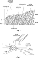

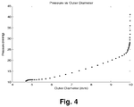
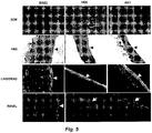
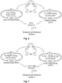
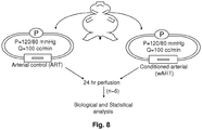


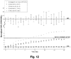

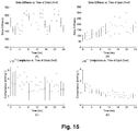

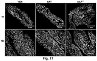


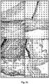
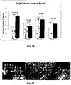
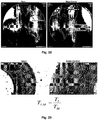

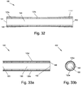


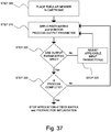
Classifications
-
- A—HUMAN NECESSITIES
- A61—MEDICAL OR VETERINARY SCIENCE; HYGIENE
- A61F—FILTERS IMPLANTABLE INTO BLOOD VESSELS; PROSTHESES; DEVICES PROVIDING PATENCY TO, OR PREVENTING COLLAPSING OF, TUBULAR STRUCTURES OF THE BODY, e.g. STENTS; ORTHOPAEDIC, NURSING OR CONTRACEPTIVE DEVICES; FOMENTATION; TREATMENT OR PROTECTION OF EYES OR EARS; BANDAGES, DRESSINGS OR ABSORBENT PADS; FIRST-AID KITS
- A61F2/00—Filters implantable into blood vessels; Prostheses, i.e. artificial substitutes or replacements for parts of the body; Appliances for connecting them with the body; Devices providing patency to, or preventing collapsing of, tubular structures of the body, e.g. stents
- A61F2/02—Prostheses implantable into the body
- A61F2/04—Hollow or tubular parts of organs, e.g. bladders, tracheae, bronchi or bile ducts
- A61F2/06—Blood vessels
-
- A—HUMAN NECESSITIES
- A61—MEDICAL OR VETERINARY SCIENCE; HYGIENE
- A61F—FILTERS IMPLANTABLE INTO BLOOD VESSELS; PROSTHESES; DEVICES PROVIDING PATENCY TO, OR PREVENTING COLLAPSING OF, TUBULAR STRUCTURES OF THE BODY, e.g. STENTS; ORTHOPAEDIC, NURSING OR CONTRACEPTIVE DEVICES; FOMENTATION; TREATMENT OR PROTECTION OF EYES OR EARS; BANDAGES, DRESSINGS OR ABSORBENT PADS; FIRST-AID KITS
- A61F2/00—Filters implantable into blood vessels; Prostheses, i.e. artificial substitutes or replacements for parts of the body; Appliances for connecting them with the body; Devices providing patency to, or preventing collapsing of, tubular structures of the body, e.g. stents
- A61F2/02—Prostheses implantable into the body
- A61F2/04—Hollow or tubular parts of organs, e.g. bladders, tracheae, bronchi or bile ducts
- A61F2/06—Blood vessels
- A61F2/062—Apparatus for the production of blood vessels made from natural tissue or with layers of living cells
-
- A—HUMAN NECESSITIES
- A61—MEDICAL OR VETERINARY SCIENCE; HYGIENE
- A61F—FILTERS IMPLANTABLE INTO BLOOD VESSELS; PROSTHESES; DEVICES PROVIDING PATENCY TO, OR PREVENTING COLLAPSING OF, TUBULAR STRUCTURES OF THE BODY, e.g. STENTS; ORTHOPAEDIC, NURSING OR CONTRACEPTIVE DEVICES; FOMENTATION; TREATMENT OR PROTECTION OF EYES OR EARS; BANDAGES, DRESSINGS OR ABSORBENT PADS; FIRST-AID KITS
- A61F2/00—Filters implantable into blood vessels; Prostheses, i.e. artificial substitutes or replacements for parts of the body; Appliances for connecting them with the body; Devices providing patency to, or preventing collapsing of, tubular structures of the body, e.g. stents
- A61F2/02—Prostheses implantable into the body
- A61F2/04—Hollow or tubular parts of organs, e.g. bladders, tracheae, bronchi or bile ducts
- A61F2/06—Blood vessels
- A61F2/07—Stent-grafts
- A61F2002/072—Encapsulated stents, e.g. wire or whole stent embedded in lining
Definitions
- the present invention relates generally to tubular graft devices and methods of making such devices.
- the present invention provides tubular graft devices comprising a tubular member and a restrictive fiber matrix about a circumference of the tubular tissue.
- the invention relates to a device as defined by claim 1.
- invention and/or “embodiment” are used in the following, and/or features are presented as being optional, this should be interpreted in such a way that the only protection sought is that of the invention as claimed.
- Document US2006085063 describes a synthetic conduit comprising a substantially tubular body comprising circumferential polymer fibers; wherein the body has an exterior surface, an interior surface, and a lumen extending therethrough; and wherein the body has microscale features disposed at the interior surface.
- the conduit can include fibers that are electrospun.
- Coronary artery disease leading to myocardial infarction and ischemia, is currently the number one cause of morbidity and mortality worldwide.
- Current treatment alternatives consist of percutaneous transluminal angioplasty, stenting, and coronary artery bypass grafting (CABG).
- CABG can be carried out using either arterial or venous conduits and is the most effective and most widely used treatment to combat coronary arterial stenosis, with nearly 500,000 procedures being performed annually. In addition there are approximately 80,000 lower extremity bypass surgeries performed annually.
- the venous conduit used for bypass procedures is most frequently the autogenous saphenous vein and remains the graft of choice for 95% of surgeons performing these bypass procedures. According to the American Heart Association, in 2004 there were 427,000 bypass procedures performed in 249,000 patients. The long term outcome of these procedures is limited due to occlusion of the graft vessel or anastomotic site as a result of intimal hyperplasia (1H), which can occur over a timeframe of months to years.
- AVGs arterial vein grafts
- IH accounts for 20% to 40% of all AVG failures within the first 5 years.
- IH develops, to some extent, in all mature AVGs and this is regarded by many as an unavoidable response of the vein to grafting.
- IH is characterized by phenotypic modulation, followed by de-adhesion and migration of medial and adventitial smooth muscle cells (SMCs) and myofibroblasts into the intima where they proliferate. In many cases, this response can lead to stenosis and diminished blood flow through the graft. It is thought that IH may be initiated by the abrupt exposure of the veins to the dynamic mechanical environment of the arterial circulation.
- Vein segments transposed to the arterial circulation for use as bypass grafts are exposed to increased blood flow and intraluminal pressure ( Porter K E, Nydahl S, Dunlop P, Varty K, Thrush A J, and London N J.
- cyclic wall motion including bending, twisting and stretching
- Vorp D A Severyn D A, Steed D L, and Webster M W.
- the tissue responds to this perceived injury by thickening, which is thought to be an attempt to return the stress to venous levels.
- thickening which is thought to be an attempt to return the stress to venous levels.
- this response is uncontrolled and can over-compensate, leading to stenosis instead of the desired thickening or "arterialization" of the vein segment.
- a bioabsorbable (polyglactin), nonrestrictive, external sheath inhibits porcine saphenous vein graft thickening.
- IH is defined by an increase in the thickness of the inner layer of a blood vessel, typically as a result of an increased number and/or size of cells in the intima, followed by deposition of massive amounts of ECM by these cells.
- the cells contributing to this response are predominantly SMCs of medial and adventitial origin.
- IH occurs both physiologically during development as in the closure of the ductus arteriosus, and pathologically as a result of vascular injury. It is thought that AVG IH may be initiated by the abrupt exposure of the veins to the dynamic mechanical environment of the arterial circulation ( Dobrin P B, Littooy F N, and Endean E D. Mechanical factors predisposing to intimal hyperplasia and medial thickening in autogenous vein grafts. Surgery.
- the hyperplastic response is set into motion and can be described by five distinct but interrelated cell processes: 1) Phenotypic modulation of adventitial and medial SMCs from a contractile and quiescent state with low proliferative potential to a synthetic state with high proliferative potential; 2) De-adhesion of SMCs or alteration of focal adhesions with other cells and the ECM; 3) Migration of SMCs from the outer layers through the basement membrane to the intima, which requires selective reassembling of focal adhesions that allow the cell to "walk” along the ECM; 4) Proliferation; and 5) Remodeling of the tissue, reflecting the changes in ECM composition caused by the synthetic SMCs secreting collagen, elastin, fibronectin, etc., as well as matrix degrading enzymes such as the various matrix metalloproteinases (MMPs).
- MMPs matrix metalloproteinases
- Modulation of SMC phenotype is a prominent feature in the pathogenesis of IH. Plaques abundant with modified SMCs have been found in the intima as early as the second week after grafting. Fully differentiated adult SMCs demonstrate low turnover as demonstrated by low proliferation and apoptosis rates. However, 48 hours after arterial injury, 15-40% of SMCs are mitotic. This abrupt shift in functionality is related to the fact that SMCs can exist in a spectrum of phenotypes, spanning from fully synthetic to fully contractile. Synthetic SMCs respond to regulatory signals and cytokines, and are capable of ECM turnover as well as growth factor production. On the other hand, contractile SMCs respond to vasomotor signals and control vessel tone. AVGs exhibit neointimal formation within the first two months by the migration and proliferation of synthetic SMCs and by subsequent, sustained ECM accumulation, including type I collagen production, in the prolonged presence of the de-differentiated type SMCs.
- the phenotypic state of SMCs is regulated at least in part by mechanical forces, as demonstrated by the observation that cyclic stretch induces a substrate-dependent modulation of proliferation and h-caldesmon expression in vitro.
- In vivo studies have also shown the importance of mechanical injury on the phenotype of SMCs. Balloon inflation injury to the media was shown to promote ECM synthesis by SMCs as well as to decrease alpha actin content.
- neointimal SMCs of veins transposed to the arterial circulation are phenotypically altered, supporting the notion that the change from the venous to the arterial environment triggers phenotypic alteration.
- Indicators of a synthetic phenotype include the presence of increased quantities of Golgi complex and rough endoplasmic reticulum, and decreased quantities of filamentous actin.
- a contractile phenotype is demonstrated by the presence of an intact contractile apparatus indicated by the expression of contractile proteins such as smoothelin, h-caldesmon, smooth muscle myosin heavy chain, and large quantities of filamentous actin.
- Cellular de-adhesion is one of the earliest responses in the IH cascade. This process refers to an alteration in a cell's adhesion to the ECM from a state of strong adherence, with focal adhesions and stress fibers, to a state of weaker adherence, characterized by a restructuring of focal adhesions and stress fibers while maintaining a spread cell shape. SMC de-adhesion will of course allow SMC migration and proliferation which will contribute to neointima formation.
- Tenascin C (TN-C), thrombospondin 1,2 (TSP), and secreted protein acidic and rich in cysteine (SPARC) are matricellular proteins that exhibit highly regulated expression during development and cellular injury ( Murphy_Ullrich J E.
- Mitogen inducible gene 2 (Mig-2) and integrin linked kinase (ILK) are intracellular proteins involved in cellular shape modulation ( Nikolopoulos S N and Turner C E. Integrin-linked kinase (ILK) binding to paxillin 1d1 motif regulates ilk localization to focal adhesions.
- Mig-2 Mitogen inducible gene 2
- ILK integrin linked kinase
- the actions of TN-C, TSP, and SPARC on the cytoskeleton and focal adhesions are basically indistinguishable ( Greenwood J A, Theibert A B, Prestwich G D, and Murphy_Ullrich J E.
- Mig-2 has been shown to participate in the connection between cell matrix adhesions and the actin cytoskeleton as well as to modulate cell shape ( Tu Y, Wu S, Shi X, Chen K, and Wu C. Migfilin and mig-2 link focal adhesions to filamin and the actin cytoskeleton and function in cell shape modulation. Cell. 2003; 113: 37-47 ). Recent studies have indicated that ILK serves as a mediator in integrin mediated signal transduction ( Wu C. Integrin-linked kinase and pinch: Partners in regulation of cell-extracellular matrix interaction and signal transduction. Journal of Cell Science. 1999; 112 (Pt 24): 4485-9 ).
- both Mig-2 and ILK are required for maintaining focal adhesions ( Nikolopoulos S N and Turner C E. Integrin-linked kinase (ilk) binding to paxillin 1d1 motif regulates ilk localization to focal adhesions.
- Migfilin and mig-2 link focal adhesions to filamin and the actin cytoskeleton and function in cell shape modulation. Cell. 2003; 113: 37-47 ).
- FIG. 2 A schematic showing the intracellular localization of TN-C, TSP, SPARC, Mig-2 and ILK is shown in FIG. 2 .
- Matrix metalloproteinases can selectively degrade various components of the vascular ECM ( Galis Z S, Muszynski M, Sukhova G K, Simon_Morrissey E, Unemori E N, Lark M W, Amento E, and Libby P. Cytokine-stimulated human vascular smooth muscle cells synthesize a complement of enzymes required for extracellular matrix digestion. Circulation Research (Online). 1994; 75(1): 181-9 ; Newby A C, Southgate K M, and Davies M G. Extracellular matrix degrading metalloproteinases in the pathogensis of arteriosclerosis.
- Adenovirus-mediated gene transfer of the human TIMP-1 gene inhibits smooth muscle cell migration and neointimal formation in human saphenous vein.
- Tissue inhibitor of matrix metalloproteinases-1 impairs arterial neointima formation after vascular injury in mice. Circ Res. 1999; 85(12): 1186-91 ).
- expression of MMP-2 and MMP-9 was increased in human saphenous veins ( Mavromatis K, Fukai T, Tate M, Chesler N, Ku D N, and Galis Z S.
- Simvastatin inhibits human saphenous vein neointima formation via inhibition of smooth muscle cell proliferation and migration. J. Vasc. Surg. 2002; 36: 150-7 ; and George S J, Zaltsman A B, and Newby A C. Surgical preparative injury and neointima formation increase MMP-9 expression and MMP-2 activation in human saphenous vein. Cardiovasc Res. 1997; 33(2): 447-59 ) under arterial conditions. Broad spectrum MMP inhibitors such as simvastatin have been shown to inhibit neointima formation in this model ( Porter K E, Naik J, Turner N A, Dickison T, Thompson M M, and London J M.
- Simvastatin inhibits human saphenous vein neointima formation via inhibition of smooth muscle cell proliferation and migration. J. Vasc. Surg. 2002; 36: 150-7 and Porter K E, Loftus I M, Peterson M, Bell P R, London N J, and Thompson M M. Marimastat inhibits neointimal thickening in a model of human vein graft stenosis. Br J. Surg. 1998; 85(10): 1373-7 ).
- MMP-1 expression is increased in venous SMCs exposed to pulse pressure compared to static controls ( Redmond E M, Cahill P A, Hirsch M, Wang Y N, Wegmann J V, and Okada S S. Effect of pulse pressure on vascular smooth muscle cell migration: The role of urokinase and matrix metalloproteinase. Thrombosis & Haemostasis. 1999; 81(2): 293-300 ), while MMP-2 mRNA levels are increased in mouse SMCs exposed to cyclic stretch ( Grote K, Flach I, Luchtefeld M, Akin E, Holland S M, Drexler H, and Schieffer B.
- MMP-2 matrix metalloproteinase-2
- MMP-9 matrix metalloproteinase-2
- Uniaxial strain upregulates matrix-degrading enzymes produced by human vascular smooth muscle cells. Am J Physiol Heart Circ Physiol. 2003; 284(5): H1778-84 ).
- Cyclic strain of fibroblasts has been shown to increase MT-1 MMP levels ( Tyagi S C, Lewis K, Pikes D, Marcello A, Mujumdar V S, Smiley L M, and Moore C K. Stretch-induced membrane type matrix metalloproteinase and tissue plasminogen activator in cardiac fibroblast cells. J Cell Physiol. 1998; 176(2): 374-82 )[166] and decrease TIMP-1 levels ( Yamaoka A, Matsuo T, Shiraga F, and Ohtsuki H. Timp-1 production by human scleral fibroblast decreases in response to cyclic mechanical stretching. Opthalmic Research. 2001; 33(2): 98-101 ).
- SMC migration was shown to be regulated by shear stress induced EC signaling ( Bassiouny H S, Song R H, Kocharyan H, Kins E, and Glagov S. Low flow enhances platelet activation after acute experimental arterial injury. Journal of Vascular Surgery. 1998; 27(5): 910-8 ; Nakazawa T, Yasuhara H, Shigematsu K, and Shigematsu H. Smooth muscle cell migration induced by shear-loaded platelets and endothelial cells. Enhanced platelet-derived growth factor production by shear-loaded platelets. Int Angiol. 2000; 19(2): 142-6 ; Powell R J, Carruth J A, Basson M D, Bloodgood R, and Sumpio B E.
- TGF- ⁇ Transforming growth factor beta
- PDGF platelet derived growth factor
- bFGF basic fibroblast growth factor
- PDGF causes a dose dependent proliferation response in cultured SMCs ( Uzui H, Lee J D, Shimizu H, Tsutani H, and Ueda T. The role of protein-tyrosine phosphorylation and gelatinase production in the migration and proliferation of smooth muscle cells. Atherosclerosis. 2000; 149(1): 51-9 ), while TGF- ⁇ inhibits proliferation ( Mii S, Ware J A, and Kent K C. Transforming growth factor-beta inhibits human vascular smooth muscle cell growth and migration. Surgery. 1993; 114(2): 464-70 ).
- bFGF released from dead and damaged cells of autologous vein grafts promotes SMC proliferation ( Qian H, Zhang B, and Zhao H.
- MMPs While growth factors clearly play a role in IH, MMPs have also been shown to be critical for the development of arterial lesions by regulating SMC proliferation ( Southgate K M, Davies M, Booth R F, and Newby A C. Involvement of extracellular-matrix-degrading metalloproteinases in rabbit aortic smooth-muscle cell proliferation. Biochem J. 1992; 288 (Pt 1): 93-9 ; Cho A and Reidy M A. Matrix metalloproteinase-9 is necessary for the regulation of smooth muscle cell replication and migration after arterial injury. Circ Res.
- TIMPs have been shown to promote apoptosis of SMC ( Annabi B, Shedid D, Ghosn P, Kenigsberg R L, Desrosiers R R, Bojanowski M W, Beaulieu E, Nassif E, Moumdjian R, and Beliveau R. Differential regulation of matrix metalloproteinase activities in abdominal aortic aneurysms. J Vasc Surg. 2002; 35(3): 539-46 ).
- IH has been shown to be associated with increases in SMC proliferation and both increases and decreases in apoptosis. It may seem counter-intuitive that an increase in intimal apoptosis is associated with IH, a condition associated with increased cell numbers. However, it must be kept in mind that increases in cell number is but a singular event in the balance that regulates IH. That is, though there may be an absolute increase in apoptosis, a greater increase in cell proliferation would result in a net increase in cell number. For these reasons, it is important to evaluate both sides of the balance (i.e., both promoting and inhibiting factors) when assessing proliferation.
- PCNA Proliferating cell nuclear antigen
- TUNEL terminal deoxynucleotidyl transferase-mediated dUTP-biotin in situ nick end labeling
- Increased wall stress has been associated with AVG IH, and this may be a direct result of a mechanical regulation of SMC proliferation, and apoptosis.
- venous SMCs have been shown to increase their proliferation compared to arterial SMCs when exposed to arterial levels of cyclic stretch ( Predel H G, Yang Z, von_Segesser L, Turina M, Buhler F R, and Luscher T F. Implications of pulsatile stretch on growth of saphenous vein and mammary artery smooth muscle. Lancet. 1992; 340(8824): 878-9 and Dethlefsen S M, Shepro D, and D'Amore P A. Comparison of the effects of mechanical stimulation on venous and arterial smooth muscle cells in vitro.
- Liu et al. showed via bromodeoxyuridine staining and TUNEL analysis that mechanical stretch due to arterial hemodynamics induces cell death, which possibly mediates subsequent cell proliferation in a rat AVG model ( Liu B, Itoh H, Louie O, Kubota K, and Kent K C. The signaling protein rho is necessary for vascular smooth muscle migration and survival but not for proliferation. Surgery. 2002; 132(2): 317-25 ).
- Vascular remodeling typically refers to a change in the morphology or microstructure of a blood vessel in response to changes in the biomechanical environment. It is believed that this occurs as an attempt by the tissue to restore biomechanical homeostasis (i.e., to return to normal levels of shear and wall stress).
- IH is a pathological form of remodeling that includes increased intimal thickness caused by SMC migration and proliferation, increased intimal apoptosis, sclerosis of the intima and media due to increased ECM deposition, and hypertrophy of the medial and adventitial SMCs.
- Vascular cells produce the ECM components such as collagen and elastin.
- the phenotypic modulation of SMCs associated with vein grafting has been shown to alter ECM synthesis characterized by increasing collagen type I and elastin production.
- Veins used as arterial bypass grafts undergo an alteration of their ECM components, which can result in a loss of lumenal area and eventual occlusion.
- An alteration in matrix synthesis directly leads to increased collagen content in the hyperplastic neointima during the first week after injury resulting from balloon angioplasty.
- AVGs that undergo this hyperplastic remodeling exhibit decreased compliance as compared to fresh veins, which can contribute to their failure.
- a method of wrapping a tubular tissue including, without limitation, a vein, artery, urethra, intestine, esophagus, trachea, bronchi, ureter and fallopian tube.
- the tubular tissue is wrapped with a restrictive fiber matrix of a bioerodible (also referred to as biodegradable or bioresorbable) polymer about a circumference of the tubular tissue.
- a bioerodible also referred to as biodegradable or bioresorbable
- the matrix is deposited onto tubular tissue by electrospinning.
- the tubular tissue is a vein, such as a saphenous vein, that is used, for instance, in an arterial bypass procedure, such as a coronary arterial bypass procedure.
- the biodegradation rate of the polymer matrix may be manipulated, optimized or otherwise adjusted so that the matrix degrades over a useful time period. For instance, in the case of a coronary artery bypass, it is desirable that the matrix dissolves over 12 hours or more so as to prevent substantial sudden stress on the graft.
- the polymer degrades over a desired period of time so that the mechanical support offered by the polymer matrix is gradually reduced over that period and the vein would be exposed to gradually increasing levels of CWS.
- the matrix biodegrades over a period of two weeks to two years.
- the matrix biodegrades over a period of two months to one year.
- the matrix biode grates over a period of two to six months.
- the matrix can be configured such that the biodegradation rate is linear or non-linear.
- the matrix can be used as a peri-surgical tool for the modification of vein segments intended for use as an AVG.
- the modification of the vein or other tubular anatomical structure would be performed by treating the vein at bedside, immediately after removal from the body and just prior to grafting, for example and without limitation, the arterial bypass surgery.
- the polymer wrap would be electrospun onto the vein just prior to it being used for the bypass procedure.
- the polymer matrix can be used as a new vehicle for the delivery of support to AVGs. While modification of the mechanical environment of a vein graft over time could itself improve AVG patency, delivery of active agents and biological (cellular) support to AVGs may prove desirable in many instances. By tuning an electrospun polymer wrap, in which active agents and/or biologicals are incorporated, to degrade at a desired rate, the rate of delivery of these support modalities could be controlled.
- a tubular tissue graft device comprising a tubular tissue and a restrictive fiber matrix of a bioerodible polymer about a circumference of the tubular tissue.
- the matrix is typically contiguous or essentially contiguous about a circumference of at least a portion (part) of the tubular tissue.
- the tubular tissue is obtained from a vein (is venous), for example and without limitation, the venous tubular tissue is obtained from a portion of a saphenous vein.
- the tubular tissue is chosen from (obtained from an organ/tissue chosen from) one or more of an artery, urethra, intestine, esophagus, ureter, trachea, bronchi, and fallopian tube.
- the matrix of the device typically bioerodes in situ (when implanted) over a time period ranging from 12 hours to two weeks, meaning the supportive nature of the matrix is degraded over that time period, not necessarily that the matrix completely erodes.
- the device is prepared by electrospinning the polymer fibers onto the tubular tissue.
- the polymer fibers can comprise any useful bioerodible polymer composition.
- the fibers comprise a polymer comprising ester and urethane linkages, including for example and without limitation a poly(ester urethane)urea.
- the fibers comprise a polymer chosen from one or more of: a polymer derived from an alpha-hydroxy acid, a polylactide, a poly(lactide-co-glycolide), a poly(L-lactide-co-caprolactone), a polyglycolic acid, a poly(dl-lactide-co-glycolide), a poly(1-lactide-co-dl-lactide), a polymer comprising a lactone monomer, a polycaprolactone, polymer comprising carbonate linkages, a polycarbonate, polyglyconate, poly(glycolide-co-trimethylene carbonate), a poly(glycolide-co-trimethylene carbonate-co-dioxanone), a polymer comprising urethane linkages, a polyurethane, a poly(ester urethane) urea, a poly(ester urethane) urea elasto
- the polymer composition comprises a poly(ester urethane)urea with from about 25% wt. to about 75% wt. collagen.
- This polymer also may comprise elastin, for example and without limitation from about 25% wt. to about 75% wt. of a mixture of collagen and elastin, which are, according to one embodiment, in approximately (about) equal amounts.
- one or both of a cell and a therapeutic agent is associated with (attached to, absorbed into, adsorbed to, grown into, linked to, etc.) the matrix.
- a therapeutic agent e.g., drug, cytokine, chemoattractant, antibiotic, anti-inflammatory, etc.
- cells are associated with the matrix, for example and without limitation, one or more of cells chosen from stem cells, progenitor (precursor) cells, smooth muscle cells, skeletal myoblasts, myocardial cells, endothelial cells, endothelial progenitor cells, bone-marrow derived mesenchymal cells and genetically modified cells are associated with the matrix.
- a growth factor is associated with the matrix, for example and without limitation, a growth factor chosen from one or more of basic fibroblast growth factor (bFGF), acidic fibroblast growth factor (aFGF), vascular endothelial growth factor (VEGF), hepatocyte growth factor (HGF), insulin-like growth factors (IGF), transforming growth factor-beta pleiotrophin protein, midkine protein and IGF-1.
- bFGF basic fibroblast growth factor
- aFGF acidic fibroblast growth factor
- VEGF vascular endothelial growth factor
- HGF hepatocyte growth factor
- IGF insulin-like growth factors
- transforming growth factor-beta pleiotrophin protein midkine protein and IGF-1.
- a drug is associated with the matrix.
- the drug is chosen from one or more of a non-steroidal anti-inflammatory drug, an antibiotic, an anticlotting factor, an immunosuppressant, a glucocorticoid, a drug acting on an immunophilin, an interferon, a TNF binding proteins, a taxane, a statin, and a nitric oxide donor.
- the drug is chosen from one or more of an NSAID, salicylic acid, indomethacin, sodium indomethacin trihydrate, salicylamide, naproxen, colchicine, fenoprofen, sulindac, diflunisal, diclofenac, indoprofen sodium salicylamide, antiinflammatory cytokines, antiinflammatory proteins, steroidal anti-inflammatory agents, heparin, Pebac, enoxaprin, aspirin, hirudin, plavix, bivalirudin, prasugrel, idraparinux, warfarin, coumadin, clopidogrel, PPACK, GGACK, tissue plasminogen activator, urokinase, streptokinase, a glucocorticoid, hydrocortisone, betamethisone, dexamethasone, flumethasone, isoflupredone, methylpred-nisolone, pre
- Also provided herein is a method of preparing a tubular graft comprising depositing a fiber matrix of a bioerodible polymer about a perimeter (outside surface, circumference) of a tubular tissue to produce a tubular tissue graft device.
- the matrix is typically contiguous or essentially contiguous about a circumference of at least a portion (part) of the tubular tissue.
- the matrix is deposited by electrospinning. As above, the matrix typically bioerodes in situ over a time period ranging from 12 hours to two weeks.
- the tubular tissue is obtained from a vein, for example and without limitation, the venous tubular tissue is obtained from a portion of a saphenous vein.
- the tubular tissue is chosen from (obtained from an organ/tissue chosen from) one or more of an artery, urethra, intestine, esophagus, ureter, trachea, bronchi, and fallopian tube.
- the polymer fibers can comprise any useful bioerodible and biocompatible polymer composition.
- the fibers comprise a polymer comprising ester and urethane linkages, including for example and without limitation a poly(ester urethane)urea.
- the fibers comprise a polymer chosen from one or more of: a polymer derived from an alpha-hydroxy acid, a polylactide, a poly(lactide-co-glycolide), a poly(L-lactide-co-caprolactone), a polyglycolic acid, a poly(dl-lactide-co-glycolide), a poly(1-lactide-co-dl-lactide), a polymer comprising a lactone monomer, a polycaprolactone, polymer comprising carbonate linkages, a polycarbonate, polyglyconate, poly(glycolide-co-trimethylene carbonate), a poly(glycolide-co-trimethylene carbonate-co-dioxanone), a polymer comprising urethane linkages, a polyurethane, a poly(ester urethane) urea, a poly(ester urethane) urea elasto
- the polymer composition comprises a poly(ester urethane)urea with from about 25% wt. to about 75% wt. collagen, including increments therebetween.
- This polymer also may comprise elastin, for example and without limitation from about 25% wt. to about 75% wt. of a mixture of collagen and elastin, which are, according to one embodiment, in approximately (about) equal amounts.
- the method comprises associating one or both of a cell and a therapeutic agent (e.g., drug, cytokine, chemoattractant, antibiotic, anti-inflammatory, etc.) is associated with (attached to, absorbed into, adsorbed to, grown into, linked to, etc.) the matrix.
- a therapeutic agent e.g., drug, cytokine, chemoattractant, antibiotic, anti-inflammatory, etc.
- cells are associated with the matrix, for example and without limitation, one or more of cells chosen from stem cells, progenitor (precursor) cells, smooth muscle cells, skeletal myoblasts, myocardial cells, endothelial cells, endothelial progenitor cells, bone-marrow derived mesenchymal cells and genetically modified cells are associated with the matrix.
- a growth factor is associated with the matrix, for example and without limitation, a growth factor chosen from one or more of basic fibroblast growth factor (bFGF), acidic fibroblast growth factor (aFGF), vascular endothelial growth factor (VEGF), hepatocyte growth factor (HGF), insulin-like growth factors (IGF), transforming growth factor-beta pleiotrophin protein, midkine protein and IGF-1 is associated with the matrix.
- bFGF basic fibroblast growth factor
- aFGF acidic fibroblast growth factor
- VEGF vascular endothelial growth factor
- HGF hepatocyte growth factor
- IGF insulin-like growth factors
- transforming growth factor-beta pleiotrophin protein midkine protein
- IGF-1 insulin-like growth factors
- the drug is chosen from one or more of a non-steroidal anti-inflammatory drug, an antibiotic, an anticlotting factor, an immunosuppressant, a glucocorticoid, a drug acting on an immunophilin, an interferon, a TNF binding proteins, a taxane, a statin, and a nitric oxide donor.
- the drug is chosen from one or more of an NSAID, salicylic acid, indomethacin, sodium indomethacin trihydrate, salicylamide, naproxen, colchicine, fenoprofen, sulindac, diflunisal, diclofenac, indoprofen sodium salicylamide, antiinflammatory cytokines, antiinflammatory proteins, steroidal anti-inflammatory agents, heparin, Pebac, enoxaprin, aspirin, hirudin, plavix, bivalirudin, prasugrel, idraparinux, warfarin, coumadin, clopidogrel, PPACK, GGACK, tissue plasminogen activator, urokinase, streptokinase, a glucocorticoid, hydrocortisone, betamethisone, dexamethasone, flumethasone, isoflupredone, methylpred-nisolone, pre
- a cardiac bypass method comprising bypassing a coronary artery with a tubular tissue graft device comprising a vein and a contiguous restrictive fiber matrix of a bioerodible polymer about a circumference of the vein.
- the contiguous bioerodible polymer matrix is any matrix as described above and throughout this disclosure, and may include additional therapeutic agents as described above.
- a method of mechanically conditioning an arterial vein graft, or any tubular tissue, typically, but not exclusively, in autologous, allogeneic xenogeneic transplantation procedures is provided herein.
- a method of wrapping tubular tissue including, without limitation, a vein, artery, urethra, intestine, trachea, esophagus, ureter and fallopian tube (meaning that any portion of those tissue sources for the graft, and not implying that the entire stated anatomical structure is used for the graft purposes, though use of the entire structure or substantially the entire structure is one option.
- tubular tissue is said to be a vein, such as a saphenous vein, this does not mean that the entire saphenous vein has to be used).
- the structure is wrapped with a restrictive fiber matrix of a bioerodible polymer about a circumference of the tubular tissue.
- a "fiber” an elongated, slender, elongated, thread-like and/or filamentous structure.
- a “matrix” is any two- or three-dimensional arrangement of elements (e.g., fibers), either ordered (e.g., in a woven or non-woven mesh) or randomly-arranged (as is typical with a mat of fibers typically produced by electrospinning).
- the matrix typically is substantially or essentially contiguous about a circumference of a tubular tissue, meaning that the matrix forms a continuous, supportive ring on a surface and about a circumference of a portion, but not necessarily over the entire surface (e.g., length) of the tubular tissue.
- the matrix is "restrictive,” meaning that the matrix is in substantial contact with the outer surface of the tubular tissue and restricts, hinders and/or prevents substantial circumferential expansion of the tubular tissue when grafted.
- the degree of restriction by the matrix typically is such that under typical arterial pressures, the tubular tissue is prevented from distending to substantially a maximum distension diameter for that tissue (see, e.g., FIG. 4 ).
- the matrix can be elastic, so long as it is restrictive. Where the matrix is bioerodible, the restrictive nature of the matrix declines over time as the matrix erodes.
- the matrix is deposited onto a tubular tissue, such as a tubular anatomical structure or organ by electrospinning.
- the anatomical structure is a vein, such as a saphenous vein, that is used, for instance, in an arterial bypass procedure, such as a coronary arterial bypass procedure.
- electrospinning is a useful method of depositing substantially uniform fibers onto such a surface.
- Electrospinning permits fabrication of scaffolds that resemble the scale and fibrous nature of the native extracellular matrix (ECM).
- ECM extracellular matrix
- the ECM is composed of fibers, pores, and other surface features at the sub-micron and nanometer size scale. Such features directly impact cellular interactions with synthetic materials such as migration and orientation.
- Electrospinning also permits fabrication of oriented fibers to result in scaffolds with inherent anisotropy. These aligned scaffolds can influence cellular growth, morphology and ECM production. For example, Xu et al.
- the process of electrospinning involves placing a polymer-containing fluid (e.g, a polymer solution, a polymer suspension, or a polymer melt) in a reservoir equipped with a small orifice, such as a needle or pipette tip and a metering pump.
- a polymer-containing fluid e.g, a polymer solution, a polymer suspension, or a polymer melt
- a small orifice such as a needle or pipette tip and a metering pump.
- One electrode of a high voltage source is also placed in electrical contact with the polymer-containing fluid or orifice, while the other electrode is placed in electrical contact with a target (typically a collector screen or rotating mandrel).
- the polymer-containing fluid is charged by the application of high voltage to the solution or orifice (e.g., about 3-15 kV) and then forced through the small orifice by the metering pump that provides steady flow.
- the application of the high voltage causes the otherwise hemispherically shaped polymer-containing fluid at the orifice to elongate to form a conical shape known as a Taylor cone.
- the repulsive electrostatic force of the charged polymer-containing fluid overcomes the surface tension and a charged jet of fluid is ejected from the tip of the Taylor cone and accelerated towards the target, which typically is biased between -2 to -10 kV.
- a focusing ring with an applied bias can be used to direct the trajectory of the charged jet of polymer-containing fluid.
- an applied bias e.g. 1-10 kV
- the fluid is a polymer solution or suspension
- the solvent typically evaporates during mid-flight, leaving behind a polymer fiber on the biased target.
- the fluid is a polymer melt, the molten polymer cools and solidifies in mid-flight and is collected as a polymer fiber on the biased target.
- a non-woven, porous mesh matrix
- the properties of the electrospun elastomeric matrices can be tailored by varying the electrospinning conditions. For example, when the biased target is relatively close to the orifice, the resulting electrospun mesh tends to contain unevenly thick fibers, such that some areas of the fiber have a "bead-like" appearance. However, as the biased target is moved further away from the orifice, the fibers of the non-woven mesh tend to be more uniform in thickness. Moreover, the biased target can be moved relative to the orifice. In certain embodiments, the biased target is moved back and forth in a regular, periodic fashion, such that fibers of the non-woven mesh are substantially parallel to each other.
- the resulting non-woven mesh may have a higher resistance to strain in the direction parallel to the fibers, compared to the direction perpendicular to the fibers.
- the biased target is moved randomly relative to the orifice, so that the resistance to strain in the plane of the non-woven mesh is isotropic.
- the target can also be a rotating mandrel.
- the properties of the non-woven mesh may be changed by varying the speed of rotation.
- the properties of the electrospun elastomeric scaffold may also be varied by changing the magnitude of the voltages applied to the electrospinning system.
- the electrospinning apparatus includes an orifice biased to 12 kV, a target biased to -7 kV, and a focusing ring biased to 3 kV.
- a useful orifice diameter is 0.047" (I.D.) and a useful target distance is about 23 cm.
- a useful range of high-voltage to be applied to a polymer suspension or melt is from 0.5-30 kV, more preferably 5-25 kV, even more preferably 10-15 kV.
- Electrospinning may be performed using two or more nozzles, wherein each nozzle is a source of a different polymer solution.
- the nozzles may be biased with different biases or the same bias in order to tailor the physical and chemical properties of the resulting non-woven polymeric mesh.
- many different targets may be used.
- a mandrel may be used as a target.
- the concentration of the polymeric component in the suspension can also be varied to modify the physical properties of the elastomeric scaffold.
- the concentration of the polymeric component in the suspension can also be varied to modify the physical properties of the elastomeric scaffold.
- the concentration of the polymeric component in the suspension can also be varied to modify the physical properties of the elastomeric scaffold.
- the concentration of the polymeric component in the suspension can also be varied to modify the physical properties of the elastomeric scaffold.
- the concentration of the polymeric component in the suspension can also be varied to modify the physical properties of the elastomeric scaffold.
- the concentration of the polymeric component in the suspension can also be varied to modify the physical properties of the elastomeric scaffold.
- the concentration of the polymeric component in the suspension can also be varied to modify the physical properties of the elastomeric scaffold.
- the concentration of the polymeric component in the suspension can also be varied to modify the physical properties of the elastomeric scaffold.
- the concentration of the polymeric component in the suspension can also be varied
- the mandrel In use, the mandrel is placed inside a tubular tissue, such as a vein, and polymer fibers are deposited about the circumference of at least a portion of the tissue by rotation of the mandrel.
- the mandrel can be reciprocated longitudinally between the spinneret and collector to increase the coverage of the tubular tissue.
- Thickness of the matrix can be controlled by either adjusting the viscosity of the polymer composition to be deposited and/or adjusting duration of the electrospinning.
- Use of more viscous polymer composition may result in thicker fibers, requiring less time to deposit a matrix of a desired thickness.
- Use of a less viscous polymer composition may result in thinner fibers, requiring increased deposition time to deposit a matrix of a desired thickness.
- the thickness of the matrix and fibers within the matrix affects the speed of bioerosion of the matrix. These parameters are optimized, depending on the end-use of the matrix, to achieve a desired or optimal physiological effect.
- the biodegradation rate of the polymer matrix may be manipulated, optimized or otherwise adjusted so that the matrix degrades over a useful time period. For instance, in the case of a coronary artery bypass, it is desirable that the matrix dissolves over 12 hours or more so as to prevent substantial sudden stress on the graft.
- the polymer degrades over a desired period of time so that the mechanical support offered by the polymer matrix is gradually reduced over that period and the vein would be exposed to gradually increasing levels of CWS.
- the matrix can be used as a peri-surgical tool for the modification of vein segments intended for use as an AVG.
- the modification of a vein or other tubular tissue or anatomical structure may be performed at bedside, immediately after removal from the body and just prior to grafting, for example and without limitation, during arterial bypass surgery.
- the polymer wrap would be electrospun onto the vein just prior to it being used for the bypass procedure.
- the polymer matrix can be used as a vehicle for the delivery of support to AVGs. While modification of the mechanical environment of a vein graft over time could itself improve AVG patency, delivery of active agents and biological (cellular) support to AVGs may prove desirable in many instances. By tuning an electrospun polymer wrap, in which active agents and/or biologicals are incorporated, to degrade at a desired rate, the rate of delivery of these support modalities could be controlled.
- a polyglactin based biodegradable sheath to reduce IH in AVGs ( Jeremy J Y, Bulbulia R, Johnson J L, Gadsdon P, Vijayan V, Shukla N, Smith F C, and Angelini G D.
- a bioabsorbable (polyglactin), nonrestrictive, external sheath inhibits porcine saphenous vein graft thickening. J Thorac Cardiovasc Surg. 2004; 127(6): 1766-72 ; Vijayan V, Shukla N, Johnson J L, Gadsdon P, Angelini G D, Smith F C, Baird R, and Jeremy J Y.
- An external AVG sheath developed by Liao et al. was designed to degrade at a desired rate in order to transfer CWS to an AVG gradually over time.
- Poly lactic-co glycolic acid sheets were prefabricated into tubes by wrapping around a Teflon rod, and therefore are not customizable to each AVG ( Liao S W, Lu X, Putnam A J, and Kassab G S.
- Kanjickal et al. used a poly(ethylene glycol) hydrogel for sustained local delivery of cyclosporine to AVGs, and successfully reduced anastomotic IH development ( Kanjickal D, Lopina S, Evancho-Chapman M M, Schmidt S, Donovan D, and Springhetti S. Polymeric sustained local drug delivery system for the prevention of vascular intimal hyperplasia. J Biomed Mater Res A. 2004; 68(3): 489-95 ). In another study, Cagiannos et al.
- a biodegradeable polymer is "biocompatible" in that the polymer and degradation products thereof are substantially non-toxic, including non-carcinogenic and non-immunogenic, and are cleared or otherwise degraded in a biological system, such as an organism (patient) without substantial toxic effect.
- Non-limiting examples of degradation mechanisms within a biological system include chemical reactions, hydrolysis reactions, and enzymatic cleavage.
- Biodegradable polymers include natural polymers, synthetic polymers, and blends of natural and synthetic polymers.
- natural polymers include chitosan, collagen, elastin, alginate, cellulose, polyalkanoates, hyaluronic acid, or gelatin.
- Natural polymers can be obtained from natural sources or can be prepared by synthetic methods (including by recombinant methods) in their use in the context of the technologies described herein.
- Non-limiting examples of synthetic polymers include: homopolymers, heteropolymers, co-polymers and block polymers or co-polymers.
- polymer composition is a composition comprising one or more polymers.
- polymers includes homopolymers, heteropolymers, co-polymers, block polymers, block co-polymers and can be both natural and synthetic.
- homopolymers contain one type of building block, or monomer, whereas co-polymers contain more than one type of monomer.
- polymers comprising monomers derived from alpha-hydroxy acids including polylactide, poly(lactide-co-glycolide), poly(L-lactide-co-caprolactone), polyglycolic acid, poly(dl-lactide-co-glycolide), poly(1-lactide-co-dl-lactide); monomers derived from esters including polyhydroxybutyrate, polyhydroxyvalerate, polydioxanone and polygalactin; monomers derived from lactones including polycaprolactone; monomers derived from carbonates including polycarbonate, polyglyconate, poly(glycolide-co-trimethylene carbonate), poly(glycolide-co-trimethylene carbonate-co-dioxanone); monomers joined through urethane linkages, including polyurethane, poly(ester urethane) urea elastomer.
- the polymer composition comprises one or both of a collagen and an elastin.
- Collagen is a common ECM component and typically is degraded in vivo at a rate faster than many synthetic bioerodable polymers. Therefore, manipulation of collagen content in the polymer composition can be used as a method of modifying bierosion rates in vivo.
- Collagen may be present in the polymer composition in any useful range, including, without limitation, from about 2% wt. to about 95% wt., but more typically in the range of from about 25% wt. to about 75% wt., inclusive of all ranges and points therebetween, including from about 40% wt. to about 75%, including about 75% wt.
- Elastin may be incorporated into the polymer composition in order to provide increased elasticity. Use of elastin can permit slight circumferential expansion of the restrictive matrix in order to assist the tubular tissue, such as a vein, adapt to its new function, such as an arterial use. Elastin may be present in the polymer composition in any useful range, including without limitation, from about 2% wt. to about 50% wt., inclusive of all ranges and points therebetween, including from about 40% wt. and about 42.3% wt., inclusive of all integers and all points therebetween and equivalents thereof. In one non-limiting embodiment, collagen and elastin are present in approximately equal amounts in the polymer composition.
- the sum of the collagen and elastin content in the polymer composition is in any useful range, including, without limitation, from about 2% wt. to about 95% wt., but more typically in the range of from about 25% wt. to about 75% wt., inclusive of all ranges and points therebetween, including from about 40% wt. to about 75%, including about 75% wt. and about 42.3% wt.
- collagen may be stated as being present in a polymer composition at 10% wt., but, due to measurement variation, may be literally present at 10% wt. ⁇ 0.05% wt., 0.10% wt. or 1.0% wt., and is likely to function in the same manner at such weight percentages.
- patient or “subject” refers to members of the animal kingdom including but not limited to human beings.
- a polymer “comprises” or is “derived from” a stated monomer if that monomer is incorporated into the polymer.
- the incorporated monomer that the polymer comprises is not the same as the monomer prior to incorporation into a polymer, in that at the very least, certain terminal groups are incorporated into the polymer backbone.
- a polymer is said to comprise a specific type of linkage if that linkage is present in the polymer.
- biodegradable polymers described herein are said to be bioerodible.
- bioerodible it is meant that the polymer, once implanted and placed in contact with bodily fluids and tissues, will degrade either partially or completely through chemical reactions with the bodily fluids and/or tissues, typically and often preferably over a time period of hours, days, weeks or months.
- Non-limiting examples of such chemical reactions include acid/base reactions, hydrolysis reactions, and enzymatic cleavage.
- the polymers contain labile chemical moieties, examples of which include esters, anhydrides, polyanhydrides, or amides.
- the polymers may contain peptides or biomacromolecules as building blocks which are susceptible chemical reactions once placed in situ.
- the polymer may contain the peptide sequence alanine-alanine-lysine, which confers enzymatic lability to the polymer.
- the polymer may include an extracellular matrix protein as a building block, such as collagen.
- the polymer or polymers typically will be selected so that it degrades in situ over a time period to optimize mechanical conditioning of the tissue.
- useful in situ degradation rates include between 12 hours and 2 weeks, and increments of 1, 2, 3, 6, 12, 24 and/or 48 hours therebetween.
- the biodegradable polymers useful herein also can be elastomeric.
- any elastomeric polymer that has properties similar to that of the soft tissue to be replaced or repaired is appropriate.
- the polymers used to make the wrap are highly distensible.
- suitable polymers include those that have a breaking strain of from 100% to 1700%, more preferably between 200% and 800%, and even more preferably between 325% and 600%.
- the breaking strain of the polymer is between 5% and 50%, more preferably between 10% and 40%, and even more preferably between 20% and 30%.
- the initial modulus is between 10 kPa to 100 MPa, more preferably between 10 and 90 MPa, and even more preferably between 20 and 70 MPa.
- the polymers used herein also release therapeutic agents when they degrade within the patient's body.
- the individual building blocks of the polymers may be chosen such that the building blocks themselves provide a therapeutic benefit when released in situ through the degradation process.
- one of the polymer building blocks is putrescine, which has been implicated as a substance that causes cell growth and cell differentiation.
- the fibers comprise a biodegradable poly(ester urethane) urea elastomer (PEUU).
- PEUU biodegradable poly(ester urethane) urea elastomer
- An example of such a PEUU is an elastomeric polymer made from polycaprolactonediol (MW 2000) and 1,4-diisocyanatobutane, with a diamine, such as putrescine as the chain extender.
- a suitable PEUU polymer may be made by a two-step polymerization process whereby polycaprolactonediol (MW 2000), 1,4-diisocyanatobutane, and putrescine are combined in a 2:1:1 molar ratio.
- a 15 wt % solution of 1,4-diisocyanatobutane in DMSO is stirred continuously with a 25 wt % solution of diol in DMSO.
- stannous octoate is added and the mixture is allowed to react at 75° C. for 3 hours, with the addition of triethylamine to aid dissolution.
- the elastomeric polymer may also be a poly(ether ester urethane) urea elastomer (PEEUU).
- the PEEUU may be made by reacting polycaprolactone-b-polyethylene glycol-b-polycaprolactone triblock copolymers with 1,4-diisocyanatobutane and putrescine.
- PEEUU is obtained by a two-step reaction using a 2:1:1 reactant stoichiometry of 1,4-diisocyanatobutane:triblock copolymer:putrescine.
- a 15 wt % solution of 1,4-diisocyanatobutane in DMSO is stirred continuously with a 25 wt % solution of triblock compolymer diol in DMSO.
- stannous octoate is added and the mixture is allowed to react at 75° C. for 3 hours.
- the reaction mixture is then cooled to room temperature and allowed to continue for 18 h.
- the PEEUU polymer solution is then precipitated with distilled water and the wet polymer is immersed in isopropanol for 3 days to remove unreacted monomer and dried under vacuum.
- At least one therapeutic agent is added to the bioerodible fibers.
- Useful therapeutic agents include any substance that can be coated on, attached, absorbed, adsorbed, embedded or otherwise associated with the bioerodible fibers that would provide a therapeutic benefit to a patient.
- Therapeutic agent may be blended with the polymer while the polymer is being processed.
- the therapeutic agent may be dissolved in a solvent (e.g., DMSO) and added to the polymer blend during processing.
- the therapeutic agent is mixed with a carrier polymer (for example and without limitation, a polyethylene glycol hydrogel or polylactic-glycolic acid microparticles) which is subsequently processed with the elastomeric polymer.
- the rate of release of the therapeutic agent may be controlled by the rate of polymer degradation.
- a bioerodible hydrogel comprising an active agent or cells is applied to the bioerodible fibers after they are applied to a surface of a tubular tissue.
- tubular does not refer specifically to a geometrically perfect tube having a constant diameter and a circular cross-section. It also embraces tissues having non-circular and varying cross sections, and can have a variable diameter, and thus any shape having a contiguous wall surrounding a lumen (that is, they are hollow), and two openings into the lumen such that a liquid, solid or gas can travel from one opening to the other.
- specific non-limiting, but illustrative examples of tubular tissues include arterial, urethral, intestinal, esophageal, ureter, tracheal, bronchial, and fallopian tube tissue.
- bioerodible fibers include, without limitation, anti-inflammatories, such as, without limitation, NSAIDs (non-steroidal anti-inflammatory drugs) such as salicylic acid, indomethacin, sodium indomethacin trihydrate, salicylamide, naproxen, colchicine, fenoprofen, sulindac, diflunisal, diclofenac, indoprofen sodium salicylamide, antiinflammatory cytokines, and antiinflammatory proteins or steroidal anti-inflammatory agents); antibiotics; anticlotting factors such as heparin, Pebac, enoxaprin, aspirin, hirudin, plavix, bivalirudin, prasugrel, idraparinux, warfarin, coumadin, clopidogrel, PPACK (D-phenylalanyl-L-prolyl-L-arginine chloromethyl ketone) and GGACK (L-phenylalanyl-L-proly
- active agents include, without limitation: (1) immunosuppressants; glucocorticoids such as hydrocortisone, betamethisone, dexamethasone, flumethasone, isoflupredone, methylpred-nisolone, prednisone, prednisolone, and triamcinolone acetonide; (2) antiangiogenics such as fluorouracil, paclitaxel, doxorubicin, cisplatin, methotrexate, cyclophosphamide, etoposide, pegaptanib, lucentis, tryptophanyl-tRNA synthetase, retaane, CA4P, AdPEDF, VEGF-TRAP-EYE, AG-103958, Avastin, JSM6427, TG100801, ATG3, OT-551, endostatin, thalidomide, becacizumab, neovastat; (3) antiproliferatives such
- Cells may be microintegrated within the restrictive, bioerodible matrix using a variety of methods.
- the matrix may be submersed in an appropriate growth medium for the cells of interest, and then directly exposed to the cells. The cells are allowed to proliferate on the surface and interstices of the matrix. The matrix is then removed from the growth medium, washed if necessary, and implanted.
- electrospun non-woven fabrics often have pore sizes that are relatively small (e.g., compared to the pore sizes of non-woven fabrics fabricated by other methods such as salt leaching or thermally induced phase separation)
- culturing cells on the surface of the scaffold is usually used when microintegration of cells only near the surface of the elastomeric scaffold is desired.
- the cells of interest are dissolved into an appropriate solution (e.g., a growth medium or buffer) and then sprayed onto a restrictive, bioerodible matrix while the matrix is being formed by electrospinning.
- an appropriate solution e.g., a growth medium or buffer
- pressure spraying i.e., spraying cells from a nozzle under pressure
- the cells are electrosprayed onto the non-woven mesh during electrospinning.
- electrospraying involves subjecting a cell-containing solution with an appropriate viscosity and concentration to an electric field sufficient to produce a spray of small charged droplets of solution that contain cells.
- SMCs smooth muscle cells
- These different conditions include spraying alone, spraying onto a target charged at -15 kV, spraying onto a target charged at -15 kV with PEUU electro spinning, electrospraying at 10 kV onto a target charged at -15 kV, and electrospraying at 10 kV onto a target charged at -15 kV with PEUU electrospinning.
- a significant reduction in SMC viability resulted from spraying cells through the nozzle.
- the cells that may be incorporated on or into the bioerodibe matrix include stem cells, progenitor (precursor) cells, smooth muscle cells, skeletal myoblasts, myocardial cells, endothelial cells, endothelial progenitor cells, bone-marrow derived mesenchymal cells and genetically modified cells.
- the genetically modified cells are capable of expressing a therapeutic substance, such as a growth factor.
- suitable growth factors include angiogenic or neurotrophic factor, which optionally may be obtained using recombinant techniques.
- growth factors include basic fibroblast growth factor (bFGF), acidic fibroblast growth factor (aFGF), vascular endothelial growth factor (VEGF), hepatocyte growth factor (HGF), insulin-like growth factors (IGF), transforming growth factor-beta pleiotrophin protein, midkine protein.
- bFGF basic fibroblast growth factor
- aFGF acidic fibroblast growth factor
- VEGF vascular endothelial growth factor
- HGF hepatocyte growth factor
- IGF insulin-like growth factors
- transforming growth factor-beta pleiotrophin protein midkine protein.
- the growth factor is IGF-1.
- the autogenous saphenous vein remains the graft of choice for both coronary (500,000 annually) and peripheral (80,000 annually) arterial bypass procedures. Failure of AVGs remains a major problem, and patients with failed grafts will die or require re-operation. IH accounts for 20% to 40% of all AVG failures. It is believed that IH is triggered by abrupt exposure of AVGs to the harsh new biomechanical environment of the arterial circulation and the elevated levels of CWS associated with the arterial system (140-fold increase compared to native venous conditions). The working hypothesis herein is that the IH response may be reduced or eliminated by more gradually exposing AVGs to arterial levels of CWS.
- each sample was mounted into a standard X-ray diffraction holder for analysis so that the fiber orientation was parallel to the X-ray beam.
- the samples were run on a PANalytical X'Pert Pro diffractometer using copper radiation.
- PEUU number average and weight average molecular weight were 228,700 and 87,600, respectively, resulting in a polydispersity index of 2.61.
- DSC demonstrated a glass transition temperature of -54.6° C. and a melt temperature of the PEUU soft segment at 41.0° C.
- This example describes one method of producing a highly cellularized blood vessel construct that is capable of also providing substantial elastomeric mechanical support.
- the method involves a micro-integrated approach wherein a meshwork of submicron elastomeric fibers is built into a vessel wall with or without the cellular placement process.
- Cellularity can be developed through in vitro culture methods or in vivo. These methods are applicable to the coating of tubular tissues as described herein.
- This example provides a method to luminally surface seed small diameter electrospun polyurethane conduits that may be used for coating tubular tissues as described herein. Electrospinning technology is used to incorporate cells during scaffold fabrication to better encourage tissue development.
- Poly(ester urethane) urea was synthesized from poly( ⁇ -caprolactone)diol and 1,4-diisocyanatobutane with putrescine chain extension.
- PEUU was dissolved at 6% wt. in hexafluoroisopropanol and electrospun.
- Electrospinning conditions included a solution volumetric flowrate of 1.0 mL/hr, a distance between nozzle and target of 13.5 cm, and voltages of +12 kV to the nozzle and -3 kV to the target.
- the target used for fabrication of small diameter tubes for implantation was a Type 316 stainless steel mandrel of 1.3 mm diameter that was rotating at 250 rpm.
- the mandrel was also translating along its axis 8 cm on a linear stage at a speed of approximately 8 cm/s to produce a more uniform conduit thickness. Samples were electrospun for 15 min to produce porous tubular constructs with wall thicknesses on the order of 150 to 200 ⁇ m For endothelialization studies a 4.7 mm stainless mandrel was instead utilized with the same process conditions.
- PEUU at 6% wt. in HFIP was electrospun onto a negatively charged rotating mandrel at 250 rpm to produce a tubular construct.
- the electrospun tubes possessed 1.3 mm inner diameters, lengths up to 8 cm and wall thicknesses of 150-200 ⁇ m Fiber sizes approximately in the range of 1000 ⁇ m were.
- these constructs were suturable and retained their lumens.
- the mandrel was dipped in 70% ethanol in order to more easily remove it from the steel mandrel.
- the conduit was then rinsed in deionized water multiple times, blotted dry and then dried under vacuum at room temperature 24 to 48 h. Conduits were then examined for their gross structure with a dissecting microscope or their fibrous morphologies with scanning electron microscopy. In order to view an uninterrupted fibrous cross-section, samples were dipped in liquid N 2 for 1 min and then fractured before sputter-coating for SEM.
- PEUU conduits (4.7 mm) were positioned inside a custom designed rotational vacuum seeding device and seeded with 20x10 6 muscle derived stem cells (MDSCs). More specifically, the electrospun conduit was placed on metal stubs and a light vacuum was applied to the exterior of the conduit. Subcultured MSDCs were then perfused through the lumen of the conduit and forced into the fibrous lumen side wall of the tube by vacuum. Constructs were cultured under static conditions in Petri dishes for 24 h. After 24 h of static culture, cells were viable, adhered to the lumen and formed a monolayer.
- MDSCs muscle derived stem cells
- Porous 1.3 mm inner diameter tubular electrospun scaffolds were implanted as interposition grafts in the abdominal aorta of rats. Constructs were suturable and easily retained their lumens in vivo.
- Female Lewis rats weighing 250-300 g were anesthetized with 1% isofluorane and 2.5 2.5 mg/100 g ketamine. A mid-abdominal incision was performed and the retroperitoneal cavity exposed. The descending aorta below renal level was dissected, clamped proximally and distally sectioned to make a 1 cm gap. The electrospun conduit was then implanted in an end-to-end manner using 10.0 prolene sutures.
- Intravenous heparin was administered before clamping with 200 Units/kg. The abdominal wall was closed in two layers with 2.0 Vycril sutures. Rats were able to recover from the surgeries with limb function. Rats were sacrificed at 2 wks and sample explants fixed in 10% neutral buffered formalin at room temperature. At 2 wks after implantation, grafts remained patent and functional. Samples were then embedded in paraffin and sectioned before staining with Hematoxylin and Eosin or Masson's Trichrome. Hematoxylin and eosin staining demonstrated external capsule formation around the explanted grafts.
- this example provides methods for fabricating a highly cellularized blood vessel construct that also provides substantial elastomeric mechanical support.
- the previous model was an in vivo approach in a biodegradable and cytocompatible, elastomeric poly(ester urethane) urea was electro spun into small diameter tubes appropriate for implantation in a rat model.
- This example provides an in vitro approach, wherein SMCs were seeded into electrospun nanofibers concurrently with scaffold fabrication using a microintegration technique.
- Vascular smooth muscle cells (SMCs) isolated from rat aortas were expanded on tissue culture polystyrene (TCPS) culture plates under Dulbecco's Modified Eagle Medium (DMEM) supplemented with 10% fetal bovine serum and 1% penicillin-streptomycin. Microintegration was performed similar to described previously with some modifications to allow for a smaller diameter electrospraying/electro spinning mandrel.
- TCPS tissue culture polystyrene
- DMEM Dulbecco's Modified Eagle Medium
- 7.5 ⁇ 10 6 SMCs/mL were subcultured in medium and fed at 0.11 mL/min into a sterile Type 316 stainless steel capillary charged at 8.5 kV and located 4.5 cm from the target.
- 6% wt. PEUU or 6% wt. PEUU/collagen (75/25) in HFIP was fed at 1.5 mL/min into a capillary charged at 12 kV and located 23 cm from the target.
- the target consisted of a sterile stainless steel mandrel (4.7 mm diameter) charged at -3 kV and rotating at 250 rpm while translating 8-cm along its axis at 1.6 mm/s. A fabrication time of 30 min was used to produce each microintegrated conduit.
- conduit and mandrel were gently placed with aseptic technique into a roller bottle and cultured statically for 16 h. After 16 h, samples were gently removed from the mandrel for culture. Samples were then cut into 15 mm lengths and sutured to metal stubs and perfused media with pulsatile flow for 3 days in device substantially as shown in FIG. 3 .
- samples were characterized.
- a MTT mitochondrial assay was used to measure cell viability.
- samples were fixed in 10% neutral buffered formalin at room temperature. Samples were then embedded in paraffin, sectioned and stained with hematoxylin and eosin. Samples were analyzed for their biomechanical properties immediately after fabrication. Properties measured included ring strength, dynamic compliance, and burst pressure.
- stainless steel staples were inserted into 5 mm long tubular sections and then into the grips of a uniaxial tensile tester (ATS). Using a 10 lb load cell and a displacement rate of 10.05 mm/min samples were strained until break.
- a porcine mammary artery was used as a control for comparison with microintegrated PEUU in compliance studies.
- burst pressure the sample outlet was sealed and flow was increased until tube rupture. The maximum pressure before rupture was taken as the burst pressure.
- Ring strength, burst pressure, and suture retention strength were assessed in the micro integrated constructs after fabrication.
- Small tube sections (rings) were mechanically robust and flexible with maximum stress and strain values of 6.3 MPa and 170% respectively. The ring samples did not break cleanly in each case and seemed to pull apart or delaminate past the ultimate stress value.
- samples were exposed to pulsatile flow and the pressure/diameter relationship was evaluated. This relationship was compared with a porcine mammary artery (pMA) exposed to the same pulsatile flow. The mechanical response of both the pMA and microintegrated PEUU was very similar with values falling for both samples falling between one another.
- pMA porcine mammary artery
- Compliance values were 1.02 ⁇ 0.33 ⁇ 10 -3 mmHg -1 for pMA and 0.71 ⁇ 0.13 ⁇ 10 -3 mmHg -1 for SMC microintegrated PEUU. Burst pressure values for all samples were greater than 1500 mmHg. The burst pressure values were approximations due to the porous nature of the microintegrated tubes.
- This method produced highly cellularized elastomeric scaffolds.
- Cells were viable after fabrication and proliferated under perfusion culture.
- an AVG is essentially a rigid tube due to the degree of its over distension ( Stooker W, Gok M, Sipkema P, Niessen H W, Baidoshvili A, Westerhof N, Jansen E K, Wildevuur C R, and Eijsman L. Pressure-diameter relationship in the human greater saphenous vein. Ann Thorac Surg. 2003; 76(5): 1533-8 ). To confirm this we performed a pressure ramping experiment. The results of this experiment are shown in FIG. 4 . It can be seen that the vein reaches maximum distension at approximately 30 mmHg. Consequently, at arterial levels of pressure a vein is very stiff, and we hope to counteract this phenomenon by providing temporary external structural support with a biodegradable adventitial wrap.
- the degree of AVG distension is directly related to vein properties such as compliance, which, in turn, is related to patency rates according to Davies et al. ( Davies A H, Magee T R, Baird R N, and Horrocks M. Prevention of malalignment during non-reversed femorodistal bypass. Ann R Coll Surg Engl. 1992; 74(6): 434-5 and Davies A H, Magee T R, Baird R N, Sheffield E, and Horrocks M. Pre-bypass morphological changes in vein grafts. Eur J Vasc Surg. 1993; 7(6): 642-7 ), who reported lower patency rates of less compliant AVGs in peripheral bypass surgery.
- Veins are inherently less compliant than arteries ( Tai N R, Salacinski H J, Edwards A, Hamilton G, and Seifalian A M. Compliance properties of conduits used in vascular reconstruction. Br J. Surg. 2000; 87(11): 1516-24 ) and become even less compliant upon abruptly exposed arterialization ( Jacot J G, Abdullah I, Belkin M, Gerhard-Herman M, Gaccione P, Polak J F, Donaldson M C, Whittemore A D, and Conte M S. Early adaptation of human lower extremity vein grafts: Wall stiffness changes accompany geometric remodeling. J Vasc Surg. 2004; 39(3): 547-55 ). It appears as though change in AVG compliance is an important predictor of AVG failure.
- the data provided herein cover two distinct areas of ongoing research: i) investigation of the mechanopathobiological response of intact vein segments to arterial hemodynamics and ii) development of a biodegradable electrospun polymer for use as an adventitial wrap.
- FIG. 3 shows such a device.
- This device permits ex vivo exposure of porcine internal jugular vein segments to precisely controlled hemodynamics and dissolved gases (pH, pO 2 , pCO 2 ) to simulate various conditions, including the venous and realistic AVG environment. Achieving these controlled conditions is accomplished using two independent perfusion/organ culture systems (shown schematically in FIG. 3 ).
- the closed loop perfusion design allows the circulation of sterile perfusate (tissue culture Media 199 supplemented with 1% fetal bovine serum, 0.5 g/fiter Cefoxitin).
- a second roller pump circulates an adventitial bath (DMEM with 1% fetal bovine serum and 0.5 g/liter Cefoxitin) around the specimen, which is mounted in a sealed chamber.
- DMEM adventitial bath
- the roller pump and flow resistors of the perfusion loop are set to provide nonpulsatile flow of 20 ml/min and pressure of 20 mmHg.
- the pump and flow resistors are set to provide a pulsatile pressure waveform of 120/80 mmHg and a mean perfusate flow of 100 ml/min.
- the "AVG conditioning" regimen will begin first by setting the perfusion system to provide arterial conditions as described above.
- the circumferential wall stress in a perfused vein segment will be controlled via the application of a tuned biodegradable perivascular electrospun polymer wrap. That is, the midvein-wall circumferential wall stress vs.
- time profile will involve the gradual imposition from venous (approximately 25 KPa) levels to arterial (approximately 140 KPa peak) levels, increasing linearly over a 24 or 192 hour period. Achieving this desired degradation rate would make in vivo mechanical conditioning of AVGs a possible treatment alternative perhaps improving patency rates in all AVGs.
- tissue viability analysis of vein segments perfused under venous vs. arterial conditions was performed and the results to baseline level of tissue viability was compared.
- Scanning electron micrography, H&E staining, Live/DeadTM staining, and TUNEL analyses were performed after 48 hours of ex vivo perfusion (see FIG. 5 ). Scanning electron micrography and H&E staining indicated that the morphologic integrity of the tissue was intact after harvesting and after 48 hours of perfusion. Live/dead and TUNEL analyses showed no significant necrosis or apoptosis, respectively, in either the venous or arterial conditions when compared to baseline at 48 hours.
- FIG. 6 is a schematic showing this experimental design, which is also described in detail below.
- PIJVs porcine internal jugular vein segments
- EVPS validated ex vivo vascular perfusion system
- FIG. 8 is a schematic showing this experimental design, which is also described in detail below.
- Bilateral PIJVs were surgically harvested from juvenile pigs and tied into separate, independent EVPSs (see below).
- Vascular perfusion experiments were carried out for 24 or 72 hours since the majority of the endpoints under investigation have been successfully detected within a few hours of these time points (see references in Table 1, above).
- the tissue was processed (see below) for biological assays to assess the endpoints outlined in Table 1.
- the porcine internal jugular vein was chosen as a model because of its similarity in inner diameter and wall thickness to the human greater saphenous vein, and because this tissue has previously been used to investigate the pathologic response of veins exposed to arterial hemodynamic conditions.
- the surgical harvest procedure was performed in the manner of a saphenectomy for bypass. Briefly, the anesthetized animal was placed in supine position, cervical incisions were made bilaterally, and dissection was done in layers to the vascular fascia of the neck. Each PIJV was identified and dissected proximal to the jugular confluence and distal to the jugular foramen. All tributaries were identified and carefully ligated to avoid leakage.
- the segment was cannulated on each end with duck billed vessel cannulae.
- a custom-designed vascular clamp Ligush J, Labadie R F, Berceli S A, Ochoa J B, and Borovetz H S. Evaluation of endothelium-derived nitric oxide mediated vasodilation utilizing ex vivo perfusion of an intact vessel. J Surg Res. 1992; 52(5): 416-21 ) was attached onto the ends of the cannulae to maintain the in vivo length of the vessel following removal. The vessel was then cut on either side between the clamped cannulae and the ligations.
- the vessels were placed in a sterile transport box (containing lactated ringers solution supplemented with heparin (500 units/liter), papaverine (60 mg/liter), and Cefoxitin (1.0 g/liter). The time between tissue harvest and mounting into the perfusion system described below was always less than one hour.
- the biodegradable polymer composite used to form the adventitial wrap was based on the poly(ester urethane)urea (PEUU) material developed by Guan et al. ( Guan J, Sacks M S, Beckman E J, and Wagner W R. Synthesis, characterization, and cytocompatibility of elastomeric, biodegradable poly(ester-urethane)ureas based on poly(caprolactone) and putrescine. J Biomed Mater Res. 2002; 61(3): 493-503 ) and further characterized in electrospun format by Stankus et al. ( Stankus J J, Guan J, and Wagner W R.
- PEUU was synthesized from poly( ⁇ -caprolactone)diol and 1,4-diisocyanatobutane with putrescine chain extension. PEUU, collagen, and elastin were combined in solution in 1,1,1,3,3,3-hexafluoro-2-propanol (HFIP), and then electrospun onto a PIJV segment using a procedure explained in detail elsewhere ( Stankus J J, Guan J, and Wagner W R. Fabrication of biodegradable elastomeric scaffolds with sub-micron morphologies. J Biomed Mater Res A. 2004; 70(4): 603-14 ).
- HFIP 1,1,1,3,3,3-hexafluoro-2-propanol
- electrospinning conditions included a mixture solution volumetric flowrate of 0.28 ⁇ L/s, a distance between nozzle and target of 17 cm, and electrical charges of +12 kV to the nozzle and -3 kV to the target.
- the target used for fabrication of spun AVGs for implantation was a Type 316 stainless steel mandrel of 3 mm diameter that was carefully inserted into the AVG lumen to avoid endothelial injury.
- the mandrel and coaxial vein were rotated together at 250 rpm, and translated axially on a linear stage at a speed of approximately 8 cm/s over 10 cm to produce a more uniform coating thickness.
- Vein segments were mounted in our well established, validated ex vivo vascular perfusion/organ culture system (EVPS, see, e.g., Labadie R F, Antaki J F, Williams J L, Katyal S, Ligush J, Watkins S C, Pham S M, and Borovetz H S. Pulsatile perfusion system for ex vivo investigation of biochemical pathways in intact vascular tissue. Am J. Physiol. 1996; 270(2 Pt 2): H760-8 ; Severyn D A, Muluk S C, and Vorp D A. The influence of hemodynamics and wall biomechanics on the thrombogenicity of vein segments perfused in vitro. J Surg Res.
- the closed loop perfusion design allows the circulation of sterile perfusate (tissue culture Media 199 supplemented with 1% fetal bovine serum and 1.0 g/liter cefoxitin) through the vascular segment as well as circulation of an adventitial bath (DMEM with 1% fetal bovine serum and 1.0 g/liter cefoxitin) within a sealed chamber. Both the perfusate and bathing media were maintained at 37° C. and physiologic levels of dissolved gasses. Experiments utilized one of two simulated hemodynamic conditions ( Severyn D A, Muluk S C, and Vorp D A. The influence of hemodynamics and wall biomechanics on the thrombogenicity of vein segments perfused in vitro. J Surg Res.
- the system was set to provide a pulsatile pressure waveform of 120/80 mmHg with a mean perfusate flow of 100 ml/min.
- Separate experiments were performed to examine unwrapped veins under VEN or ART conditions, and wrapped veins under ART conditions (wART). Each perfusion experiment lasted for 24 hours with intraluminal pressure, outer diameter and flowrate being measured every hour. Vein segments were then analyzed either histologically or via immunohistochemistry as described below.
- FIG. 6 is a schematic depicting the first set of ex vivo experiments that were performed. In these experiments we evaluated the beneficial effects of a biodegradable electrospun polymer wrap on PIJVs the abrupt exposure of PIJVs to ART conditions vs. PIJVs exposed to VEN conditions for 24 hours.
- FIG. 7 is a schematic depicting the second set of ex vivo experiments that were performed. In these experiments we evaluated the effects of a mechanical conditioning paradigm (cART conditions) on PIJVs vs. PIJVs abruptly exposed to ART conditions for 24 and 72 hours.
- cART conditions mechanical conditioning paradigm
- FIG. 8 is a schematic depicting the third set of ex vivo experiments that were performed. We evaluated the beneficial effects a tuned biodegradable polymer wrap on PIJVs to ART conditions (wART conditions) vs. unwrapped PIJVs exposed to ART conditions for 24 hours.
- FIG. 9 For biomechanical modeling purposes, consider the schematic in FIG. 9 showing an idealized cross section of the vein/wrap complex.
- the outer layer of the bi-layer compound tube is taken as the electrospun polymer wrap and the concentric inner layer is the vein segment.
- outer vessel diameter (D) was continuously measured with a laser micrometer ( Labadie R F, Antaki J F, Williams J L, Katyal S, Ligush J, Watkins S C, Pham S M, and Borovetz H S. Pulsatile perfusion system for ex vivo investigation of biochemical pathways in intact vascular tissue. Am J. Physiol. 1996; 270(2 Pt 2): H760-8 ; Brant A M, Rodgers G J, and Borovetz H S. Measurement in vitro of pulsatile arterial diameter using a helium-neon laser. J Appl Physiol.
- endpoints can be grouped into three categories based on the required tissue processing: i) histology (including micro/ultrastructure); ii) RNA analysis; and iii) protein analysis. All vein segments were segmented and processed according to FIG. 10 .
- the biological endpoints proposed for above can be characterized as either histological or molecular-based with respect to the type of assay required.
- the histological endpoints included evaluation of microstructure, apoptosis, proliferation, a SMC phenotype marker, and a cell-adhesion marker.
- the protein and gene expression endpoints required isolation of protein and RNA and are classified as molecular.
- the samples dedicated for histological analysis were taken from the freezer and immediately embedded in Tissue Freezing MediumTM (Triangle Biomedical Sciences, Durham, N.C.) and frozen at -65° C. Five-micron cross-sections were cut using a cryotome and placed on positively charged, glass microscope slides. Slides were stored at -80° C. until they could be processed for histological or immunohistochemical assays.
- Tissue Freezing MediumTM Triangle Biomedical Sciences, Durham, N.C.
- tissue rings were cut, washed with PBS, embedded in Tissue Freezing MediumTM (Triangle Biomedical Sciences, Durham, N.C.), and cut into 5 ⁇ m sections.
- the tissue sections were either stained with hematoxylin and eosin (H&E), Masson's trichrome (MTC), picrosirius red, or Movat's pentachrome stains. Stained tissue sections were then visualized using an Olympus Provis light microscope (Olympus, Center Valley, Pa., USA) and compared qualitatively.
- the electrospun wrapped PIJVs were examined under scanning electron microscopy (SEM).
- SEM scanning electron microscopy
- tissue segments designated for SEM were fixed in ultrapure 2.5% gluteraldehyde, dehydrated through a graded series of ethanol solutions (30-100%), critical point dried (Emscope, CPD 750, Ashford, Kent, UK), then overcoated with vaporized carbon (Cressington Freeze Fracture Device, Cressington, Cranberry, Pa., USA).
- the tissue was visualized using a JEOL JEM-6335F field emission gun SEM (JEOL, Peabody, Mass., USA).
- TUNEL In Situ Cell Death Kit, fluorescein
- DNA strand breaks were identified by incubation at 37° C. for one hour with Terminal deoxynucleotidyl transferase and fluorescein labeled dUTP (both provided in the kit from Roche). Nuclei were counterstained with Hoechst 33258. A small set of samples was treated with 100 U/ml of DNase I to serve as positive controls each time the assay was performed to ensure efficacy. All sample preparation parameters including incubation times, temperatures, and reagent concentrations were optimized using DNase I treated positive controls. Negative controls were incubated with labeled dUTP without the transferase enzyme.
- Quantification of the percent of TUNEL positive cells was performed using a manual counting procedure. Positive cells from each of 5 FOVs (field of views) from a given 5 ⁇ m cross-section were averaged to define the mean percent positive cells for that cross-section. The mean percent TUNEL positive cells from one segment ( FIG. 10 ) was determined.
- PCNA proliferating cell nuclear antigen
- the enzymatic reaction caused PCNA positive cells to stain brown which was visualized via microscope (100 ⁇ magnification) until the desired level of staining was achieved. The reaction was then stopped by placing the slides into deioinized water. For nuclear visualization, cells were counter-stained with Hematoxylin (Vector Labs, Cat.# H-3401, Burlingame, Calif.) according to manufacturer's instructions.
- FIG. 13 The results of a typical vasomotor challenge experiment are shown in FIG. 13 .
- the sham PIJV segment responded in a predictable dose-dependent manner to stimulation with EPI, while the spun PIJV exhibited a single contraction commencing with the lowest dose of EPI.
- Vasodilation in response to SNP was similar for both the control and spun PIJVs, each resulting in a larger outer diameter than that at baseline, suggesting a certain level of basal tone in both the sham and spun PIJVs.
- FIG. 14A level of contraction
- FIG. 14B dilation
- FIGS. 16A and 19C Histologic images were consistent with the SEM images in that they also showed the polymer wrap to be well attached to the adventitial surface of the vein and that it can be electrospun with an approximately uniform thickness. Further, the polymer degraded nearly completely following the 24 hour perfusion period ( FIGS. 16B and 16D ).
- FIG. 17 shows representative birefringence images of vein sections stained with picrosirius red.
- the color range from red to green indicates a range of collagen fiber organization with red being most organized and green being less organized.
- the granulated appearance of the staining indicates the natural crimped collagen fiber state, whereas stretched fibers appear striated rather than granulated.
- FIG. 18 Representative images of Movat's pentachrome stained tissue section are shown in FIG. 18 .
- the internal elastic lamina appears disrupted in the PIJVs perfused under ART conditions when compared to both VEN and wART conditions.
- this data suggests that the polymer wrap was successful in reducing the level of stretch within the vein wall when exposed to ART conditions.
- the electrospun adventitial wrap exhibited high porosity and tight adherence to the adventitial surface of the veins ( FIGS. 19A-C ), which suggests that the wrap would provide structural support to an AVG without inhibiting adventitial nutrient and gas diffusion into the tissue. Another important observation was that the electrospinning process did not appear to damage the endothelial layer, which remained continuous ( FIG. 19D ).
- FIG. 21 shows representative paired fluorescent immunohistochemistry images of TUNEL staining from all four ex vivo vascular perfusion experiments described above.
- FIG. 22 shows the quantified TUNEL analysis results from these experiments. It can be seen that there is a statistically significant increase in apoptotic cells within PIJVs abruptly exposed to ART conditions vs. VEN controls. However, the mechanical conditioning paradigm imposed via cART conditions (for both 24 and 72 hours) and via the biodegradable electrospun polymer wrap (wART conditions) statistically significantly reduced the number of apoptotic cells within PIJVs vs. ART control conditions. Proliferation
- FIG. 23 shows representative paired HRP/ABC based immunohistochemistry images of PCNA staining from all four ex vivo vascular perfusion experiments described above.
- FIG. 24 shows the quantified PCNA analysis results from these experiments. It can be seen that there is a statistically significant decrease in proliferating cells within PIJVs abruptly exposed to ART conditions vs. VEN controls. However, the mechanical conditioning paradigm imposed via cART conditions (24 hours) and via the biodegradable electrospun polymer wrap (wART conditions) statistically significantly inhibited the decrease in the number of proliferating cells within PIJVs vs. ART control conditions. The number of proliferating cells within PIJVs exposed to cART conditions for 72 hours was not statistically significantly different than ART controls.
- FIG. 25 shows representative paired HRP/ABC based immunohistochemistry images of Golgi complex staining from all four ex vivo vascular perfusion experiments described in above.
- FIG. 26 shows the quantified Golgi complex analysis results from these experiments. It can be seen that there is a statistically significant increase in the number of cells staining positive for Golgi complex within PIJVs abruptly exposed to ART conditions vs. VEN controls.
- the mechanical conditioning paradigm imposed via cART conditions (for both 24 and 72 hours) and via the biodegradable electrospun polymer wrap (wART conditions) suggests only a trend towards statistically significantly inhibiting the increase in the number of cells positively stained for Golgi complex within PIJVs vs. ART control conditions.
- a biodegradable electrospun polymer wrap can be uniformly ( FIG. 16 ) and safely ( FIGS. 13 and 14 ) electrospun onto vein segments, and that the wrap can be tuned to completely degrade ( FIG. 16 ) such that CWS is applied to an AVG at a desired rate ( FIG. 12 ).
- Having control over the biodegradation rate of an adventitially placed electrospun polymer wrap could lend itself to three potentially beneficial support modalities for attenuating IH in AVGs.
- biomechanical support can be delivered at a desired rate.
- the polymer wrap seems to provide structural support to AVGs resulting in a more naturally crimped configuration of the collagen fibers ( FIG. 17 ), as well as less damage to the internal elastic lamina ( FIG. 18 ). Maintaining integrity of the structural proteins that comprise the AVG wall may help to minimize the detrimental mechanical triggers received by the vascular ECs and SMCs and hence could help to attenuate IH in AVGs.
- VEN, cART, and wART groups was inconsistent with some published data ( Nishibe T, Miyazaki K, Kudo F, Flores J, Nagato M, Kumada T, and Yasuda K. Induction of angiotensin converting enzyme in neointima after intravascular stent placement. Int Angiol. 2002; 21(3): 250-5 ; Predel H G, Yang Z, von_Segesser L, Turina M, Buhler F R, and Luscher T F. Implications of pulsatile stretch on growth of saphenous vein and mammary artery smooth muscle. Lancet.
- Live/DeadTM assay is widely used to evaluate necrosis in living cells and tissues, it arguably was not ideally suited for our application. This was due to the limited distance the reagents were able to diffuse through the thickness of vascular tissue. It was observed that the staining occurred predominantly in the intimal and adventitial layers of the vein wall, while the media was largely devoid of signal. It is true that the adverse effect of the electrospinning process would be in the area of contact between the polymer wrap and the vein wall (i.e., the adventitia), as well as in the area of contact between the mandrel and the vein wall (i.e., the lumen).
- the Live/DeadTM assay appeared to work well in both of these areas and showed no appreciable increase in the level of necrosis when compared to control tissue. Additionally, the vasomotor challenge data indicated that the spun PIJV was able to contract with the same intensity as the sham control which demonstrated the viability of the SMCs comprising the medial layer of the tissue. Finally, we would have ideally compared the vasomotor responses of the sham and spun PIJVs to a baseline control response-that is, with a freshly excised PIJV segment. However, obtaining a third segment of PIJV for immediate testing was not feasible since we could only harvest two PIJV segments per animal. We feel that the choice of a sham control over a baseline control was acceptable in that we wanted to assess the differences associated only with electrospinning.
- a tunable polymer wrap can be applied to vein segments without compromising viability or function, and demonstrated one potential application; i.e., gradually imposing the mid-wall CWS in wrapped veins exposed to arterial levels of pressure.
- the gradual imposition of arterial levels of CWS, rather than abrupt exposure, may be an important new means to reduce the hyperplastic response of AVGs, promoting instead safe arterialization.
- PIJVs were harvested as described in Example 2 and were either spun with the same wrap composition and thickness as described in that Example using the electrospinning process described therein, or designated as sham controls. Again, for the sham PIJV segments without the electrospun polymer wrap, we mimicked the electrospinning process up to the point of actually placing the polymer wrap (i.e., including the insertion of the mandrel and rotating/translating the vein within the electrical field).
- the AVGs were then implanted as carotid interposition grafts (as described in below) for 30 days (or upon observing irreversible complications), an implant duration sufficient to allow IH to be grossly apparent in the sham control group ( Angelini G D, Bryan A J, Williams H M, Morgan R, and Newby A C. Distention promotes platelet and leukocyte adhesion and reduces short-term patency in pig arteriovenous bypass grafts. J Thorac Cardiovasc Surg. 1990; 99(3): 433-9 ; Vijayan V, Shukla N, Johnson J L, Gadsdon P, Angelini G D, Smith F C, Baird R, and Jeremy J Y.
- Animals were brought into the facility 7-10 days prior to the day of the experiment, and kept NPO 12 hours prior to surgery. Prior to surgery, animals were anesthetized with Acepromazine, 0.15 mg/kg 1M, and Ketamine, 15.0 mg/kg, IM combination, intubated and maintained at a surgical plane of anesthesia with Isoflurane (1-3% in oxygen). Once each animal was clipped and prepped for the procedures it was moved into the surgical suite and placed on positive pressure ventilation and instrumented with monitoring equipment (ECG). Pulse oximetry and blood pressure were monitored throughout the surgical procedure. After the induction of anesthesia, aseptic surgery was performed.
- ECG positive pressure ventilation and instrumented with monitoring equipment
- mice Post-operatively, animals were recovered and housed in an intensive care unit. Following the surgical procedure and cessation of inhalation anesthesia, the animal were extubated when it exhibited a swallowing reflex and the protective cough reflexes are functional. The animals were continually monitored for 24 hours, and the following parameters were recorded every hour: pulse rate, strength of pulse, capillary refill time, respiratory rate, urinary output, and defecation. Body temperature was determined and recorded every 2 hours. The animal was kept warm and dry to prevent hypothermia. Buprenorphine hydrochloride (0.005-0.01 mg/kg, IM, q12 h) was administered at regular intervals for 4 days for pain and continued to be administered for pain management if signs of pain were exhibited.
- Buprenorphine hydrochloride (0.005-0.01 mg/kg, IM, q12 h) was administered at regular intervals for 4 days for pain and continued to be administered for pain management if signs of pain were exhibited.
- Acute pain in animals is expressed by guarding, vocalization, mutilation, restlessness, recumbency for an unusual length of time, depression (reluctance to move or difficulty in rising), or abnormal appearance (head down, tucked abdomen, hunched). Skin staples/sutures were removed 10 days post-op. All animals were monitored daily by a trained staff of Veterinarians, Registered Veterinary Technicians, and animal care personnel.
- An anti-coagulation regimen was used to battle acute AVG failure via thrombosis.
- Oral doses of aspirin (325 mg/day) and Plavix (75 mg/day) were both started 3 days pre-operatively.
- the Aspirin was administered daily for the entire 30 day post-operative period, and Plavix was administered daily for only 14 days post-operatively.
- the animals were euthanized.
- the pigs were deeply anesthetized with Acepromazine, 0.15 mg/kg 1M, and Ketamine, 30.0 mg/kg, IM combination, and the animals were then euthanized by injection of an overdose of intravenous potassium chloride to induce cardiac arrest. Vital signs were monitored to effect.
- angiography was performed to assess graft patency.
- the carotid artery was clamped approximately 3 cm upstream of the proximal graft anastomosis, and contrast medium was infused into the carotid artery immediately distal to the clamp.
- Angiograms were recorded (Model OEC 9800 Plus, General Electric Inc.) to verify flow through the entire graft segment. If flow could not be established through a graft (ie. due to occlusion), angiography was not performed.
- the grafts were extracted and 1 ⁇ 2 the tissue was immediately fixed in 4% paraformaldehyde and analyzed histologically as described in below.
- the other 1 ⁇ 2 of the tissue was fixed in ultrapure 2.5% gluteraldehyde for SEM analysis as described in Section above.
- Morphometric analysis was performed on sections from the central region of the explanted grafts. Using standard Movat's pentachrome staining techniques, intimal and medial thicknesses were measured. The intimal to medial thickness ratios were calculated from these measurements. Measurements were made from 4 fields of view and averaged to yield a sinlge value for each AVG section.
- the adventitial polymer wrap had an immediately apparent effect of maintaining the AVG at a diameter consistent with that for the native vein (compare FIG. 27 middle and right) under arterial pressure.
- the wrapped AVGs exhibited pulsatile radial excursions (i.e., compliance) similar to the native carotid artery, whereas the un-wrapped AVG appeared to be a rigid tube with no detectable pulsations. That is, upon establishing flow through the control grafts, it was observed that unlike the native carotid arteries and spun veins, the sham control veins did not change in diameter in response to the pulsatile pressure.
- FIGS. 31A and 31B SEM images were taken of the AVGs from one completely successful experiment ( FIGS. 31A and 31B ) as well as from another experiment where the AVGs were not comletely occluded ( FIGS. 31C and 31D ).
- the anastomotic interface between the vein graft and artery, evidenced by the suture line, can be seen in each image.
- FIG. 32 a side sectional view of a tubular graft device of the present invention is illustrated, including a tubular member with a surrounding fiber matrix whose thickness varies along at least a portion of the length of the device.
- Device 100 includes tubular member 140, typically a harvested vessel graft from a patient.
- tubular member 140 may be an artificial graft, such as a Dacron, PTFE or ePTFE tube, or other tubular material well known to those of skill in the art.
- Tubular member 140 may comprise a braided structure, such as a tube or coil of solid, braided, knitted or wound material comprising a polymer of similar or different material to fiber matrix 120 or comprising a metal such as Nitinol, stainless steel, elgiloy, tantalum, MP35N, or a variety of other biocompatible metals, or a resorbing metal such as magnesium, or a combination of different materials such as mentioned above.
- Tubular member 140 includes lumen 150 from its proximal end, first end 101, to its distal end, second end 102.
- Surrounding tubular member 140 is a fiber matrix comprising first longitudinal portion 120a and second longitudinal portion 120b.
- portion 120a proximate end 101 has a thicker wall than portion 120b in the middle of device 100, which can be achieved by applying more fiber in portion 120 during the fiber deposition process (e.g. an electrospinning process).
- Portion 120c, proximate to end 102 may also have a thicker wall, such as a wall with a thickness proximating portion 120a.
- a continuous taper is provided from first end 101 to the midportion of device 100, which symmetrically reverses from the midportion to second end 102.
- a stepped wall thickness change could be employed.
- the variable wall thickness along the length of device 100 can be useful in providing multiple functions.
- the thicker portions 120a and 120c may provide better strength and/or tear resistance to support an anastomosis, such as suture or clip based end-to-side anastomosis between the first end 101 and the aorta of a patient, and second end 102 and a point distal to an obstructed artery of the patient.
- the thinner walls of portion 120b may be configured to provide reduced radial force, such as a radial force tuned to allow a vessel graft to expand at a particular rate under arterial pressure.
- the wall thickness variations of portions 120a, 120b and 120c can be configured to create particular flow conditions, support various curvilinear geometries of device 100 when implanted, prevent buckling, and provide other functions.
- portion 120a, portion 120b and/or portion 120c may have additional construction or material differences (i.e. different than thickness) such as different fiber size, different matrix porosity, and other construction differences.
- portions 120a, 120b and/or 120c may be constructed of one or more different materials such as materials with different mechanical properties such as different tear strengths, strain resistance, or biodegradation characteristics.
- one portion may include an agent such as a pharmaceutical drug or cell based agent, or one portion may include a first agent and another portion include a second, different agent.
- FIGs. 33a and 33b side and end sectional views, respectively, of a tubular graft device of the present invention are shown, including a tubular member with a surrounding fiber matrix whose thickness varies along its circumference, along at least a portion of the device.
- Device 100' includes tubular member 140, typically a harvested vessel graft from a patient or an artificial graft as has been described hereabove.
- Tubular member 140 includes lumen 150 from its proximal end, first end 101, to its distal end, second end 102.
- Surrounding tubular member 140 is a fiber matrix comprising top portion 120d and bottom portion 120e.
- top portion 120d of the circumference has a thicker wall than bottom portion 120e, which can be achieved by applying more fiber in portion 120d during the fiber deposition process (e.g. an electrospinning process).
- the variable wall thickness along the length of device 100' is preferably a continuous taper along the circumference of device 100', which can be useful in providing multiple clinical and/or mechanical functions.
- the wall thickness variations of portions 120d and 120e can be configured to create particular flow conditions, support various curvilinear geometries of device 100', prevent buckling, create a preferred expansion geometry, and provide other functions.
- portion 120d and portion 120e may have additional construction differences (i.e. different than thickness), such as different fiber size, different matrix porosity, and other construction differences.
- portion 120d and portion 120e may be constructed of one or more different materials such as materials with different mechanical properties such as different tear strengths, strain resistance, or biodegradation characteristics.
- one portion may include an agent such as a pharmaceutical drug or cell based agent, or one portion may include a first agent and another portion include a second, different agent.
- FIG. 34 a side sectional view of a tubular graft device of the present invention is illustrated, including a tubular member with a surrounding fiber matrix whose properties vary along at least a portion of the length of the device.
- Device 100 includes tubular member 140, typically a harvested vessel graft from a patient.
- tubular member 140 may be an artificial graft or other tubular material as has been described hereabove.
- Tubular member 140 includes lumen 150 from its proximal end, first end 101, to its distal end, second end 102.
- Surrounding tubular member 140 is a fiber matrix comprising first longitudinal portion 120f, second longitudinal portion 120g, and third longitudinal portion 120h.
- Portion 120f proximate first end 101 is of dissimilar construction to portion 120g at the midportion of device 100".
- Portion 120g may be of different construction than portion 120h.
- device 100" may include four or more sections with dissimilar construction. Construction of each portion may vary in numerous ways, including construction methods and geometries, as well as the fiber materials used. The variable material properties along the length of device 100" can be useful in providing multiple functions, as has been described hereabove.
- portions 120f, 120g and 120h each individually comprise a homogenous tubular section with similar construction geometry, methods and materials.
- a continous change in construction geometry, methods and/or materials is present from first end 101 to second end 102.
- device 100" includes continuously changing portions and discrete, homogenous portions.
- FIG. 35 a side sectional view of a tubular graft device of the present invention is illustrated, including a tubular member surrounded by both a fiber matrix and a second scaffolding structure.
- Device 100' includes tubular member 140, typically a harvested vessel graft from a patient.
- tubular member 140 may be an artificial graft or other tubular material as has been described hereabove.
- Tubular member 140 includes lumen 150 from its proximal end, first end 101, to its distal end, second end 102.
- fiber matrix 120 Surrounding tubular member 140 is fiber matrix 120, as has been described in detail hereabove.
- Fiber matrix 120 comprises one or more of: at least a homogenous portion; at least two different homogenous portions; and at least a portion with continuously varying properties.
- scaffold 130 Surrounding fiber matrix 120 is scaffold 130, preferably of a stent-like construction well known to those of skill in the art.
- scaffold 130 is located between tubular member 140 and fiber matrix 120, such as to protect the tubular member during the application of the fiber matrix (e.g. protect from solvents in the polymer solution, delivered heat for the polymer melt, etc.) and/or provide other functions.
- Scaffold 130 is constructed of biocompatible materials such as biocompatible metals including stainless steel and Nitinol, or biocompatible plastics such as a combination of one or more polymers.
- Scaffold 130 may be constructed of a biodegradable material, such as a material which biodegrades at a similar or dissimilar rate to a fiber matrix 120.
- Fiber matrix 120 may be a biodegradable structure and scaffold 130 a permanent structure such as to provide a radial supporting force for tubular member 140 that is at a first magnitude when first implanted, reduces over the biodegradation period, but provides force, at a second magnitude less than the first, for the life of the implant.
- Scaffold 130 may provide a homogeneous radial supporting force, or it may vary along its length, such as by providing a greater radial force proximate one or more ends of scaffold 130.
- Scaffold 130 may be resiliently biased such as to self expand or contract; may be plastically deformable, such as to be expanded or compressed to properly fit around tubular member 140; or may include both resiliently biased (e.g. self-expanding or contracting) and plastically deformable portions.
- Scaffold 130 may include one or more different portions along its length or circumference, as has been described in reference to fiber matrix 120 of the devices of Figs.
- Scaffold 130 may be of a mesh construction, such as a woven or non-woven construction using coiling, braiding, knitting or other fabrication method.
- Scaffold 130 may be constructed using techniques for membrane or film deposition and subsequently processed to create porosity such as via needle punching, laser cutting, freeze drying, thermally induced phased separation, electroporation and/or salt leaching.
- Scaffold 130 may be manufactured with pre-determined porosity and/or pore size, and may exhibit anisotropic properties.
- scaffold 130 and fiber matrix 120 may comprise a single layer or composite structure.
- the composite structure can be formed by scaffold 130 and fiber matrix 120 mechanically intertwining, melting together or otherwise residing in the same layer.
- Scaffold 130 may provide an anchoring mechanism for device 100"'.
- scaffold 130 is placed between tubular member 140 and fiber matrix 120.
- the deposited fiber matrix 120 may create a solvent bonding mechanism with scaffold 130, such as when the materials of construction of scaffold 130 and fiber matrix 120 are similar (e.g. for solvent bonding).
- the deposited fiber matrix 120 may create a temperature bonding mechanism with scaffold 130, such as when scaffold 130 is a thermoplastic polymer with a low fuse point, and scaffold 130 melts when contacted by the heated polymer of fiber matrix 120 during the fiber matrix application.
- scaffold 130 may be a flexible covering, such as a dip covering achieved by dipping tubular member 140 or tubular member 140 with fiber matrix 120 applied, into a liquid solution that results in an attached flexible covering.
- Lumen 150 may be filled and/or covered during the dipping process, such as to avoid a covering of the inner portion of tubular member 140, or the the inner portion of 140 may also include a flexible covering.
- the flexible covering may be used to provide one or more functions, such as increased radial support, or protection of device 100"' from mechanical damage or contamination.
- the flexible covering may be biodegradable, and may include one or more agents configured to be released over time.
- Scaffold 130 may include the dip covering as well as the stent-like structure of Fig. 35 .
- scaffold 130 may be an artificial graft material, such as an artificial graft material which is expanded and placed around tubular member 140 or tubular member 140 with fiber matrix 120 applied, and then released to cause fixation.
- the artificial graft is constructed of a biocompatible material such as a Dacron, PTFE, ePTFE tube, or other graft material well known to those of skill in the art.
- the artificial graft covering may be used to provide one or more functions, such as increased radial support, or protection of device 100"' from mechanical damage or contamination.
- the artificial graft may be biodegradable, and may include one or more agents configured to be released over time.
- Scaffold 130 may include the artificial graft as well as the stent-like structure of Fig. 35 and/or the dip covering described hereabove.
- Step 200 includes the performance of one or more patient assessment procedures.
- the patient assessment procedure can include assessments performed in a doctor's office or other healthcare facility including information regarding age; sex; race; blood pressure; blood test information; family history information; stress test data; and combinations of these.
- the assessment may include one or more tests or other procedures performed during an invasive patient treatment such as an assessment performed in an interventional laboratory or an operating room, such as an angiography procedure or the tubular graft device implantation procedure.
- a vessel such as a saphenous vein is harvested, and one or more observations or other tests (e.g. a sizing such as a diameter or vessel wall measurement; or a mechanical properties test such as a test of elasticity of the vessel) are performed to obtain data about the patient's harvested vessel.
- observations or other tests e.g. a sizing such as a diameter or vessel wall measurement; or a mechanical properties test such as a test of elasticity of the vessel
- Step 210 a vessel, such as a portion of a saphenous vein, is harvested form the patient.
- Step 210 can be performed during, simultaneous with, or after Step 200, such as when Step 200 includes an analysis of the harvested vessel.
- step 210 includes the fabrication of an artificial graft, such as an elongate tube constructed of a braided or extruded material.
- Harvested vessels may include veins or arteries, and may be harvested from the patient receiving the tubular graft device or a surrogate, such as an applicable human or other animal donor.
- a fiber matrix is applied to the harvested vessel or other tubular member of the present invention based on the data obtained in Step 200.
- the application of the fiber matrix may be dependent on the anatomical location for the tubular graft device to be implanted, such as when the tubular graft device would be placed in a curvilinear shape.
- One or more properties of the harvested vessel may determine the fiber matrix configuration such as to reinforce a weakened section of the harvested vessel or otherwise accommodate a geometric or structural property of that vessel.
- the configuration of the fiber matrix that is optimized or otherwise determined by a patient parameter may include by is not limited to: fiber matrix profile such as a constant or variable thickness; fiber matrix material or combination of materials; fiber matrix radial and/or circumferential and/or axial strengths; fiber matrix radial and/or circumferential and/or axial stiffnesses; fiber matrix bending stiffness; fiber matrix elastic and/or viscoelastic properties; fiber diameter distribution; fiber degradation rate, fiber matrix degradation rate, fiber matrix diffusion properties, fiber matrix wettability; and combinations of these.
- the thickness of the fiber matrix is tailored to accommodated or modify the mechanical reinforcement of the underlying vessel (e.g., underlying vein). That is, the deposition thickness of the fiber matrix is customized according to the Law of Laplace, in this example, to provide a stabilized, reinforced underlying vessel based on a patient's vein assessment. In general, larger veins require more fiber matrix wall thickness than smaller ones to obtain a similar level of mechanical reinforcement. To compensate or to modify mechanical reinforcement based on vessel or vein size, fiber matrix deposition can be customized.
- the size of a mandrel i.e., a vessel holding tool during fiber matrix deposition
- a male sizing tool fitted within the inner lumen of the tubular vessel or vein, which substantially matches or accommodates the harvested vein or selected tubular vessel.
- the outer diameter of the vessel can be measured using a female sizing tool, such as a sterile credit card sized sheet with several holes identified by size.
- This measurement, or patient assessment can occur in a single process or the measurement can be made using the average of a few measurements across the length of the vessel to help take account of variability.
- the measurement can be mapped along the entire length of the vessel so that the desired thickness at each location along the length is known.
- the desired thickness of fiber matrix deposition can be determined by estimating the level of required material tensile strength/tension (for each of the two cylindrical directions) to be withstood by the tubular fiber matrix in order to support the luminal pressurization (static and/or dynamic) and geometrical configuration (static and/or dynamic) of the tubular vessel or vein underneath it without experiencing plastic deformation.
- the level of required material tensile strength/tension will be overestimated by a desired safety factor.
- a non-limiting example of a method used to customize the mechanical requirements of the fiber matrix is based on the required circumferential strength of the material, which is defined as the tensile circumferential force per unit of tubular fiber matrix axial length.
- the strength of each specific material is proportional to its thickness and can be characterized empirically using a tensile testing apparatus for different thicknesses of material.
- the polymer flow rates or other deposition variables can be altered to achieve customized mechanical reinforcement.
- This process of tailoring deposition conditions based on patient assessment i.e., inner and outer diameter vessel measurements
- the fiber matrix application may include the delivery of multiple types of fibers, such as two or more fibers with different mechanical properties that are delivered simultaneously or sequentially.
- Step 300 includes placing a tubular member, such as a harvested vessel or artificial graft, onto a holder, such as a mandrel configured to hold a tubular structure during deposition or other application of a fiber matrix, such as an electrospinning process described in detail hereabove.
- a tubular member such as a harvested vessel or artificial graft
- a holder such as a mandrel configured to hold a tubular structure during deposition or other application of a fiber matrix
- an electrospinning process described in detail hereabove.
- Numerous processes may be used alternative or in addition to an electrospinning process, including but not limited to: wet spinning; dry spinning; gel spinning; melt spinning; and other processes configured to apply a fiber matrix.
- Step 310 the fiber matrix application process is initiated.
- Numerous process input parameters are used in the fiber matrix application process, as has been described in detail hereabove.
- the typical and/or preferred process input parameters are selected from the values of Table 3 herebelow.
- Process parameters regarding relative movement of the material application device (e.g. nozzle) to the tubular graft may be accomplished by moving the material application device, the tubular graft, or both.
- process input parameter that achieve a fiber matrix with one or more portions that include continuously changing properties and/or a fiber matrix with one or more homogenous portions.
- the fiber matrix comprises at least one homogeneous portion; at least two different homogeneous portions; at least a portion with continuously varying properties; and combinations of these.
- Monitored process output parameters typically include the current tubular graft device diameter and/or thickness. Numerous output parameters can be monitored such as parameters selected from the group consisting of the current (real time) values of: temperature such as device temperature and/or room temperature, room humidity, deposition rate, deposition duration, solvent concentration, viscosity, electrical field strength, mandrel rotation speed, nozzle translation speed, nozzle distance from target; and combinations of these.
- Step 320 which occurs continuously during the application process of Step 310, a comparison of the monitored output parameters is made between this measured value and a target or specification value, hereinafter the process target values.
- a process target value may be a discrete value or a range of preferred and/or acceptable values for one or more process parameters. If one or more process output parameters are determined to be out of specification, Step 325 is performed wherein a process input parameter is adjusted. Adjusted process input parameter may include but are not limited to: temperature such as device temperature and/or room temperature, humidity, deposition rate, deposition duration, solvent concentration, viscosity, electrical field strength, mandrel rotation speed, nozzle translation speed, nozzle distance from target; and combinations of these.
- the process input parameter changed may include a change to the material being deposited or a change to the mix of materials being deposited.
- Step 330 is performed in which a process completion check is performed.
- Process completion can be determined in one or more ways, such as the completion of a predetermined process time, or the confirmation that one or more process parameters has reached its intended goal (e.g. desired thickness of the tubular graft device and/or applied fiber matrix.) If process completion is confirmed, the tubular graft device is ready for implantation. If process completion is not confirmed, Steps 310 and 320 continue until completion.
- the method of Fig. 37 may further include additional analysis of the tubular graft device and/or a component of the tubular graft device.
- the analysis may require the application step to be temporarily stopped, and potentially the incomplete tubular graft device to be removed from the holding device.
- the analysis may be included prior to placing the tubular member on the holding device, or after the fiber application deposition has been completed. This analysis may produce information related to one or more of: device or matrix thickness, device or matrix stiffness, amount of polymer deposited, quantification of solvent in matrix, presence of a puncture; and presence or burning of the tubular memember such as burning of a vein.
- the results of the analysis may require the tubular graft device to be discarded (i.e. not implanted in the patient).
Applications Claiming Priority (2)
| Application Number | Priority Date | Filing Date | Title |
|---|---|---|---|
| US25569909P | 2009-10-28 | 2009-10-28 | |
| PCT/US2010/054444 WO2011056705A2 (en) | 2009-10-28 | 2010-10-28 | Bioerodible wraps and uses therefor |
Publications (3)
| Publication Number | Publication Date |
|---|---|
| EP2493418A2 EP2493418A2 (en) | 2012-09-05 |
| EP2493418A4 EP2493418A4 (en) | 2015-11-18 |
| EP2493418B1 true EP2493418B1 (en) | 2017-03-15 |
Family
ID=43970694
Family Applications (1)
| Application Number | Title | Priority Date | Filing Date |
|---|---|---|---|
| EP10828927.3A Active EP2493418B1 (en) | 2009-10-28 | 2010-10-28 | Bioerodible wraps and uses therefor |
Country Status (8)
| Country | Link |
|---|---|
| US (3) | US9622849B2 (ja) |
| EP (1) | EP2493418B1 (ja) |
| JP (2) | JP2013509258A (ja) |
| AU (1) | AU2010315417B2 (ja) |
| BR (1) | BR112012009626A2 (ja) |
| CA (1) | CA2778459C (ja) |
| IL (1) | IL219334A (ja) |
| WO (1) | WO2011056705A2 (ja) |
Families Citing this family (30)
| Publication number | Priority date | Publication date | Assignee | Title |
|---|---|---|---|---|
| JP2013509258A (ja) | 2009-10-28 | 2013-03-14 | ユニバーシティ オブ ピッツバーグ オブ ザ コモンウェルス システム オブ ハイヤー エデュケイション | 生体浸食性ラップおよびそのための使用 |
| EP2512369B8 (en) | 2009-12-16 | 2017-05-17 | Neograft Technologies, Inc. | Graft devices and methods of use |
| CA2785989A1 (en) | 2009-12-31 | 2011-07-07 | Neograft Technologies, Inc. | Graft devices and methods of fabrication |
| EP2582868B1 (en) | 2010-06-17 | 2018-03-28 | Washington University | Biomedical patches with aligned fibers |
| WO2012012407A2 (en) | 2010-07-19 | 2012-01-26 | Neograft Technologies, Inc. | Graft devices and methods of use |
| WO2012097229A2 (en) | 2011-01-14 | 2012-07-19 | Neograft Technologies, Inc. | Apparatus for creating graft devices |
| WO2012109309A2 (en) * | 2011-02-09 | 2012-08-16 | Neograft Technologies, Inc. | System and mandrel for creating graft devices |
| JP5665803B2 (ja) * | 2011-07-15 | 2015-02-04 | クック メディカル テクノロジーズ エルエルシーCook Medical Technologies Llc | グラフト層をエレクトロスピニングする方法 |
| US9155610B2 (en) | 2011-12-13 | 2015-10-13 | Neograft Technologies, Inc. | System and atraumatic mandrel for creating graft devices |
| WO2013163358A1 (en) | 2012-04-24 | 2013-10-31 | Harvard Bioscience, Inc. | Engineered tissue scaffolds and supports therefor |
| WO2014004746A2 (en) | 2012-06-26 | 2014-01-03 | Harvard Bioscience, Inc. | Methods and compositions for promoting the structural integrity of scaffolds for tissue engineering |
| NL2009145C2 (en) * | 2012-07-06 | 2014-01-07 | Xeltis B V | Implant. |
| EP2897561B1 (en) | 2012-09-21 | 2020-11-04 | Washington University | Biomedical patches with spatially arranged fibers |
| WO2014110300A1 (en) | 2013-01-09 | 2014-07-17 | Harvard Apparatus Regenerative Technology | Synthetic scaffolds |
| US20140249618A1 (en) * | 2013-02-18 | 2014-09-04 | Elutin, Inc. | Site specific drug delivery wraps, systems and methods of use thereof |
| WO2015048224A1 (en) | 2013-09-25 | 2015-04-02 | Johnson Jed K | Fiber scaffolds for use creating implantable structures |
| WO2015051042A2 (en) * | 2013-10-01 | 2015-04-09 | Harvard Apparatus Regenerative Technology, Inc. | Meshes and patches for tissue repair |
| US20160287374A1 (en) * | 2013-11-15 | 2016-10-06 | Neograft Technologies, Inc. | Graft devices and related systems and methods |
| US9687239B2 (en) | 2014-04-15 | 2017-06-27 | Abbott Cardiovascular Systems Inc. | Intravascular devices supporting an arteriovenous fistula |
| CN108495599B (zh) * | 2015-11-12 | 2020-07-31 | 博奥司时代有限责任公司 | 用于在吻合术部位或其他生理部位产生胃肠道组织的系统和方法 |
| JP2019503819A (ja) * | 2016-01-08 | 2019-02-14 | バイオステージ,インコーポレイテッド | 吻合または生理学的位置における胃腸組織の生成のためのシステムおよび方法 |
| WO2017192145A1 (en) * | 2016-05-06 | 2017-11-09 | University Hospitals Health Systems, Inc. | Ureteral stent |
| US10632228B2 (en) | 2016-05-12 | 2020-04-28 | Acera Surgical, Inc. | Tissue substitute materials and methods for tissue repair |
| JP7165330B2 (ja) * | 2017-05-08 | 2022-11-04 | 慶應義塾 | 多層構造体とその製造方法及び利用方法 |
| WO2019237014A1 (en) | 2018-06-08 | 2019-12-12 | Neograft Technologies, Inc. | Multiple layer vascular graft |
| US20210338412A1 (en) * | 2018-10-05 | 2021-11-04 | Board Of Regents Of The University Of Nebraska | Bypass graft |
| CA3154767A1 (en) * | 2019-09-30 | 2021-04-08 | University Of Pittsburgh - Of The Commonwealth System Of Higher Education | Extracellular matrix devices and methods of manufacture |
| JPWO2021177273A1 (ja) | 2020-03-03 | 2021-09-10 | ||
| CA3211698A1 (en) * | 2021-02-23 | 2022-09-01 | Iviva Medical, Inc. | Biomatrix-impregnated porous conduit for tissue engineering |
| CN115154650B (zh) * | 2022-07-08 | 2023-07-21 | 四川昇嘉科技有限公司 | 氨基酸介导的山椒素全天然功能凝胶的制备方法及应用 |
Family Cites Families (50)
| Publication number | Priority date | Publication date | Assignee | Title |
|---|---|---|---|---|
| US5609626A (en) | 1989-05-31 | 1997-03-11 | Baxter International Inc. | Stent devices and support/restrictor assemblies for use in conjunction with prosthetic vascular grafts |
| US5723004A (en) | 1993-10-21 | 1998-03-03 | Corvita Corporation | Expandable supportive endoluminal grafts |
| JP2719752B2 (ja) * | 1994-03-24 | 1998-02-25 | パイロットプレシジョン株式会社 | 接ぎ木方法及び台木と穂木とを接合するための棒状部材の供給装置 |
| US20030086975A1 (en) | 2001-11-08 | 2003-05-08 | Timothy Ringeisen | Method for making a porous Polymeric material |
| US6036702A (en) | 1997-04-23 | 2000-03-14 | Vascular Science Inc. | Medical grafting connectors and fasteners |
| US6187038B1 (en) | 1998-04-08 | 2001-02-13 | Sulzer Carbomedics Inc. | Small bore biologic graft with therapeutic delivery system |
| AU1603800A (en) | 1998-11-06 | 2000-05-29 | St. Jude Medical Cardiovascular Group, Inc. | Medical graft component and methods of installing same |
| US6113612A (en) | 1998-11-06 | 2000-09-05 | St. Jude Medical Cardiovascular Group, Inc. | Medical anastomosis apparatus |
| US6296863B1 (en) | 1998-11-23 | 2001-10-02 | Agion Technologies, Llc | Antimicrobial fabric and medical graft of the fabric |
| US20020081732A1 (en) | 2000-10-18 | 2002-06-27 | Bowlin Gary L. | Electroprocessing in drug delivery and cell encapsulation |
| CN1087621C (zh) | 1999-07-21 | 2002-07-17 | 高迎春 | 一种烧伤烫伤药膏 |
| US7037332B2 (en) | 2000-03-15 | 2006-05-02 | Orbus Medical Technologies, Inc. | Medical device with coating that promotes endothelial cell adherence |
| EP1315756A2 (en) | 2000-09-01 | 2003-06-04 | Virginia Commonwealth University Intellectual Property Foundation | Electroprocessed fibrin-based matrices and tissues |
| AU2002230941A1 (en) * | 2000-10-31 | 2002-05-15 | Prodesco, Inc. | Supported lattice for cell cultivation |
| US6599323B2 (en) | 2000-12-21 | 2003-07-29 | Ethicon, Inc. | Reinforced tissue implants and methods of manufacture and use |
| US20020123786A1 (en) | 2001-03-02 | 2002-09-05 | Ventrica, Inc. | Methods and devices for bypassing an obstructed target vessel by placing the vessel in communication with a heart chamber containing blood |
| AU2002241222A1 (en) | 2001-03-20 | 2002-10-03 | Nicast Ltd. | Portable electrospinning device |
| US6713011B2 (en) | 2001-05-16 | 2004-03-30 | The Research Foundation At State University Of New York | Apparatus and methods for electrospinning polymeric fibers and membranes |
| US6891077B2 (en) | 2001-07-25 | 2005-05-10 | The United States Of America As Represented By The Secretary Of The Army | Fibrinogen bandages and arterial bleeding models and methods of making and using thereof |
| US7326237B2 (en) | 2002-01-08 | 2008-02-05 | Cordis Corporation | Supra-renal anchoring prosthesis |
| CA2497349C (en) | 2002-09-26 | 2008-07-08 | Angiotech International Ag | Perivascular wraps |
| EP1555957A4 (en) | 2002-10-04 | 2010-11-24 | Nanomatrix Inc | CLOSURE FOR SKIN AND OTHER TISSUE |
| CA2417634A1 (en) | 2002-11-22 | 2004-05-22 | Emory University | Plastic and elastic protein copolymers |
| US7452374B2 (en) * | 2003-04-24 | 2008-11-18 | Maquet Cardiovascular, Llc | AV grafts with rapid post-operative self-sealing capabilities |
| US7998188B2 (en) | 2003-04-28 | 2011-08-16 | Kips Bay Medical, Inc. | Compliant blood vessel graft |
| US20050131520A1 (en) * | 2003-04-28 | 2005-06-16 | Zilla Peter P. | Compliant blood vessel graft |
| CA2523812C (en) | 2003-04-28 | 2011-06-21 | Medtronic, Inc. | Compliant venous graft |
| US7001401B1 (en) | 2003-05-06 | 2006-02-21 | Medcanica Llc | Device and method for holding a blood vessel |
| PL1633327T3 (pl) | 2003-06-04 | 2011-02-28 | Univ Georgetown | Sposób poprawienia stabilności i okresu trwałości kompleksów liposomowych |
| CN1251769C (zh) | 2003-08-29 | 2006-04-19 | 中国人民解放军第三军医大学 | 基因修饰的组织工程血管 |
| US20070173917A1 (en) | 2004-02-27 | 2007-07-26 | Fumihiro Hayashi | Composite structure and process for producing the same |
| US7775965B2 (en) | 2004-03-09 | 2010-08-17 | The Board Of Regents Of The University Of Oklahoma | Decellularized grafts from umbilical cord vessels and process for preparing and using same |
| WO2006044904A2 (en) | 2004-10-15 | 2006-04-27 | Vanderbilt University | Nano- and micro-scale engineering of polymeric scaffolds for vascular tissue engineering |
| US20060199265A1 (en) | 2005-03-02 | 2006-09-07 | Wolf Michael F | Seeding implantable medical devices with cells |
| US7759120B2 (en) | 2005-03-02 | 2010-07-20 | Kps Bay Medical, Inc. | Seeding implantable medical devices with cells |
| EP1863547B1 (en) | 2005-03-11 | 2016-05-11 | Wake Forest University Health Sciences | Tissue engineered blood vessels |
| US7531503B2 (en) | 2005-03-11 | 2009-05-12 | Wake Forest University Health Sciences | Cell scaffold matrices with incorporated therapeutic agents |
| WO2006119142A2 (en) | 2005-04-29 | 2006-11-09 | Kassab Ghassan S | Tissue engineering of blood vessels |
| US7568973B2 (en) * | 2005-09-09 | 2009-08-04 | Igt | Server based gaming system having multiple progressive awards |
| US20070239267A1 (en) | 2006-03-28 | 2007-10-11 | Medtronic Vascular, Inc. | Stent Graft With Healing Promoting Necks |
| US8696733B2 (en) * | 2006-08-29 | 2014-04-15 | C. R. Bard, Inc. | Helical high fatigue stent-graft |
| JP5973121B2 (ja) | 2007-01-30 | 2016-08-23 | ユニバーシティ オブ ピッツバーグ オブ ザ コモンウェルス システム オブ ハイヤー エデュケイション | 生体内分解性ラッピングおよびその使用 |
| KR100932688B1 (ko) | 2007-07-06 | 2009-12-21 | 한국과학기술연구원 | 인공혈관용 이중막 구조의 튜브형 다공성 스캐폴드 및 그의제조방법 |
| WO2009086458A1 (en) | 2007-12-27 | 2009-07-09 | C.R. Bard. Inc. | Vascular graft prosthesis having a reinforced margin for enhanced anastomosis |
| US8303650B2 (en) * | 2008-01-10 | 2012-11-06 | Telesis Research, Llc | Biodegradable self-expanding drug-eluting prosthesis |
| WO2009103012A1 (en) | 2008-02-14 | 2009-08-20 | Tengion, Inc. | Tissue engineering scaffolds |
| US8353814B2 (en) | 2008-10-09 | 2013-01-15 | Kips Bay Medical, Inc. | Apparatus and method for mounting an external scaffold to a vascular graft |
| US20100221304A1 (en) * | 2009-02-26 | 2010-09-02 | The Regents Of The University Of Colorado, A Body Corporate | Bionanocomposite Materials and Methods For Producing and Using the Same |
| US20110040367A1 (en) * | 2009-08-14 | 2011-02-17 | Medtronic Vascular, Inc. | Low Profile Prosthesis |
| JP2013509258A (ja) | 2009-10-28 | 2013-03-14 | ユニバーシティ オブ ピッツバーグ オブ ザ コモンウェルス システム オブ ハイヤー エデュケイション | 生体浸食性ラップおよびそのための使用 |
-
2010
- 2010-10-28 JP JP2012537051A patent/JP2013509258A/ja active Pending
- 2010-10-28 AU AU2010315417A patent/AU2010315417B2/en active Active
- 2010-10-28 BR BR112012009626A patent/BR112012009626A2/pt not_active Application Discontinuation
- 2010-10-28 EP EP10828927.3A patent/EP2493418B1/en active Active
- 2010-10-28 US US13/502,759 patent/US9622849B2/en active Active
- 2010-10-28 CA CA2778459A patent/CA2778459C/en active Active
- 2010-10-28 WO PCT/US2010/054444 patent/WO2011056705A2/en active Application Filing
-
2012
- 2012-04-22 IL IL219334A patent/IL219334A/en active IP Right Grant
-
2014
- 2014-11-28 JP JP2014241557A patent/JP6018162B2/ja active Active
-
2017
- 2017-03-08 US US15/453,115 patent/US20170340432A1/en not_active Abandoned
-
2019
- 2019-09-20 US US16/577,579 patent/US11850141B2/en active Active
Non-Patent Citations (1)
| Title |
|---|
| None * |
Also Published As
| Publication number | Publication date |
|---|---|
| BR112012009626A2 (pt) | 2017-08-08 |
| CA2778459C (en) | 2016-08-16 |
| WO2011056705A3 (en) | 2011-10-06 |
| CA2778459A1 (en) | 2011-05-12 |
| US11850141B2 (en) | 2023-12-26 |
| JP2013509258A (ja) | 2013-03-14 |
| US20120330437A1 (en) | 2012-12-27 |
| US9622849B2 (en) | 2017-04-18 |
| EP2493418A4 (en) | 2015-11-18 |
| JP6018162B2 (ja) | 2016-11-02 |
| IL219334A (en) | 2016-07-31 |
| WO2011056705A2 (en) | 2011-05-12 |
| AU2010315417B2 (en) | 2016-12-15 |
| EP2493418A2 (en) | 2012-09-05 |
| JP2015061653A (ja) | 2015-04-02 |
| US20200237494A1 (en) | 2020-07-30 |
| US20170340432A1 (en) | 2017-11-30 |
| AU2010315417A1 (en) | 2012-05-17 |
| IL219334A0 (en) | 2012-06-28 |
Similar Documents
| Publication | Publication Date | Title |
|---|---|---|
| US11850141B2 (en) | Bioerodible wraps and uses therefor | |
| US9333068B2 (en) | Bioerodible wraps and uses therefor | |
| JP6321691B2 (ja) | スカフォールドシステム | |
| US10376394B2 (en) | Scaffold system for tissue repair | |
| Wagner et al. | Bioerodible wraps and uses therefor |
Legal Events
| Date | Code | Title | Description |
|---|---|---|---|
| PUAI | Public reference made under article 153(3) epc to a published international application that has entered the european phase |
Free format text: ORIGINAL CODE: 0009012 |
|
| 17P | Request for examination filed |
Effective date: 20120528 |
|
| AK | Designated contracting states |
Kind code of ref document: A2 Designated state(s): AL AT BE BG CH CY CZ DE DK EE ES FI FR GB GR HR HU IE IS IT LI LT LU LV MC MK MT NL NO PL PT RO RS SE SI SK SM TR |
|
| DAX | Request for extension of the european patent (deleted) | ||
| A4 | Supplementary search report drawn up and despatched |
Effective date: 20151015 |
|
| RIC1 | Information provided on ipc code assigned before grant |
Ipc: A61L 27/44 20060101AFI20151009BHEP Ipc: A61B 5/02 20060101ALI20151009BHEP Ipc: A61L 27/04 20060101ALI20151009BHEP Ipc: A61F 2/07 20130101ALI20151009BHEP Ipc: A61L 27/28 20060101ALI20151009BHEP Ipc: A61F 2/06 20130101ALI20151009BHEP |
|
| REG | Reference to a national code |
Ref country code: DE Ref legal event code: R079 Ref document number: 602010040850 Country of ref document: DE Free format text: PREVIOUS MAIN CLASS: A61F0002040000 Ipc: A61L0027440000 |
|
| RIC1 | Information provided on ipc code assigned before grant |
Ipc: A61F 2/06 20060101ALI20160629BHEP Ipc: A61L 27/44 20060101AFI20160629BHEP Ipc: A61L 27/28 20060101ALI20160629BHEP Ipc: A61B 5/02 20060101ALI20160629BHEP Ipc: A61F 2/07 20130101ALI20160629BHEP Ipc: A61L 27/04 20060101ALI20160629BHEP |
|
| GRAP | Despatch of communication of intention to grant a patent |
Free format text: ORIGINAL CODE: EPIDOSNIGR1 |
|
| INTG | Intention to grant announced |
Effective date: 20160819 |
|
| GRAS | Grant fee paid |
Free format text: ORIGINAL CODE: EPIDOSNIGR3 |
|
| GRAJ | Information related to disapproval of communication of intention to grant by the applicant or resumption of examination proceedings by the epo deleted |
Free format text: ORIGINAL CODE: EPIDOSDIGR1 |
|
| GRAL | Information related to payment of fee for publishing/printing deleted |
Free format text: ORIGINAL CODE: EPIDOSDIGR3 |
|
| GRAR | Information related to intention to grant a patent recorded |
Free format text: ORIGINAL CODE: EPIDOSNIGR71 |
|
| INTC | Intention to grant announced (deleted) | ||
| GRAA | (expected) grant |
Free format text: ORIGINAL CODE: 0009210 |
|
| AK | Designated contracting states |
Kind code of ref document: B1 Designated state(s): AL AT BE BG CH CY CZ DE DK EE ES FI FR GB GR HR HU IE IS IT LI LT LU LV MC MK MT NL NO PL PT RO RS SE SI SK SM TR |
|
| INTG | Intention to grant announced |
Effective date: 20170207 |
|
| REG | Reference to a national code |
Ref country code: CH Ref legal event code: EP Ref country code: GB Ref legal event code: FG4D |
|
| REG | Reference to a national code |
Ref country code: IE Ref legal event code: FG4D |
|
| REG | Reference to a national code |
Ref country code: AT Ref legal event code: REF Ref document number: 874899 Country of ref document: AT Kind code of ref document: T Effective date: 20170415 |
|
| REG | Reference to a national code |
Ref country code: DE Ref legal event code: R096 Ref document number: 602010040850 Country of ref document: DE |
|
| REG | Reference to a national code |
Ref country code: NL Ref legal event code: MP Effective date: 20170315 |
|
| REG | Reference to a national code |
Ref country code: LT Ref legal event code: MG4D |
|
| PG25 | Lapsed in a contracting state [announced via postgrant information from national office to epo] |
Ref country code: HR Free format text: LAPSE BECAUSE OF FAILURE TO SUBMIT A TRANSLATION OF THE DESCRIPTION OR TO PAY THE FEE WITHIN THE PRESCRIBED TIME-LIMIT Effective date: 20170315 Ref country code: FI Free format text: LAPSE BECAUSE OF FAILURE TO SUBMIT A TRANSLATION OF THE DESCRIPTION OR TO PAY THE FEE WITHIN THE PRESCRIBED TIME-LIMIT Effective date: 20170315 Ref country code: NO Free format text: LAPSE BECAUSE OF FAILURE TO SUBMIT A TRANSLATION OF THE DESCRIPTION OR TO PAY THE FEE WITHIN THE PRESCRIBED TIME-LIMIT Effective date: 20170615 Ref country code: LT Free format text: LAPSE BECAUSE OF FAILURE TO SUBMIT A TRANSLATION OF THE DESCRIPTION OR TO PAY THE FEE WITHIN THE PRESCRIBED TIME-LIMIT Effective date: 20170315 Ref country code: GR Free format text: LAPSE BECAUSE OF FAILURE TO SUBMIT A TRANSLATION OF THE DESCRIPTION OR TO PAY THE FEE WITHIN THE PRESCRIBED TIME-LIMIT Effective date: 20170616 |
|
| REG | Reference to a national code |
Ref country code: AT Ref legal event code: MK05 Ref document number: 874899 Country of ref document: AT Kind code of ref document: T Effective date: 20170315 |
|
| PG25 | Lapsed in a contracting state [announced via postgrant information from national office to epo] |
Ref country code: SE Free format text: LAPSE BECAUSE OF FAILURE TO SUBMIT A TRANSLATION OF THE DESCRIPTION OR TO PAY THE FEE WITHIN THE PRESCRIBED TIME-LIMIT Effective date: 20170315 Ref country code: LV Free format text: LAPSE BECAUSE OF FAILURE TO SUBMIT A TRANSLATION OF THE DESCRIPTION OR TO PAY THE FEE WITHIN THE PRESCRIBED TIME-LIMIT Effective date: 20170315 Ref country code: RS Free format text: LAPSE BECAUSE OF FAILURE TO SUBMIT A TRANSLATION OF THE DESCRIPTION OR TO PAY THE FEE WITHIN THE PRESCRIBED TIME-LIMIT Effective date: 20170315 Ref country code: BG Free format text: LAPSE BECAUSE OF FAILURE TO SUBMIT A TRANSLATION OF THE DESCRIPTION OR TO PAY THE FEE WITHIN THE PRESCRIBED TIME-LIMIT Effective date: 20170615 |
|
| REG | Reference to a national code |
Ref country code: FR Ref legal event code: PLFP Year of fee payment: 8 |
|
| PG25 | Lapsed in a contracting state [announced via postgrant information from national office to epo] |
Ref country code: NL Free format text: LAPSE BECAUSE OF FAILURE TO SUBMIT A TRANSLATION OF THE DESCRIPTION OR TO PAY THE FEE WITHIN THE PRESCRIBED TIME-LIMIT Effective date: 20170315 |
|
| PG25 | Lapsed in a contracting state [announced via postgrant information from national office to epo] |
Ref country code: IT Free format text: LAPSE BECAUSE OF FAILURE TO SUBMIT A TRANSLATION OF THE DESCRIPTION OR TO PAY THE FEE WITHIN THE PRESCRIBED TIME-LIMIT Effective date: 20170315 Ref country code: EE Free format text: LAPSE BECAUSE OF FAILURE TO SUBMIT A TRANSLATION OF THE DESCRIPTION OR TO PAY THE FEE WITHIN THE PRESCRIBED TIME-LIMIT Effective date: 20170315 Ref country code: CZ Free format text: LAPSE BECAUSE OF FAILURE TO SUBMIT A TRANSLATION OF THE DESCRIPTION OR TO PAY THE FEE WITHIN THE PRESCRIBED TIME-LIMIT Effective date: 20170315 Ref country code: ES Free format text: LAPSE BECAUSE OF FAILURE TO SUBMIT A TRANSLATION OF THE DESCRIPTION OR TO PAY THE FEE WITHIN THE PRESCRIBED TIME-LIMIT Effective date: 20170315 Ref country code: SK Free format text: LAPSE BECAUSE OF FAILURE TO SUBMIT A TRANSLATION OF THE DESCRIPTION OR TO PAY THE FEE WITHIN THE PRESCRIBED TIME-LIMIT Effective date: 20170315 Ref country code: AT Free format text: LAPSE BECAUSE OF FAILURE TO SUBMIT A TRANSLATION OF THE DESCRIPTION OR TO PAY THE FEE WITHIN THE PRESCRIBED TIME-LIMIT Effective date: 20170315 Ref country code: RO Free format text: LAPSE BECAUSE OF FAILURE TO SUBMIT A TRANSLATION OF THE DESCRIPTION OR TO PAY THE FEE WITHIN THE PRESCRIBED TIME-LIMIT Effective date: 20170315 |
|
| PG25 | Lapsed in a contracting state [announced via postgrant information from national office to epo] |
Ref country code: SM Free format text: LAPSE BECAUSE OF FAILURE TO SUBMIT A TRANSLATION OF THE DESCRIPTION OR TO PAY THE FEE WITHIN THE PRESCRIBED TIME-LIMIT Effective date: 20170315 Ref country code: PT Free format text: LAPSE BECAUSE OF FAILURE TO SUBMIT A TRANSLATION OF THE DESCRIPTION OR TO PAY THE FEE WITHIN THE PRESCRIBED TIME-LIMIT Effective date: 20170717 Ref country code: IS Free format text: LAPSE BECAUSE OF FAILURE TO SUBMIT A TRANSLATION OF THE DESCRIPTION OR TO PAY THE FEE WITHIN THE PRESCRIBED TIME-LIMIT Effective date: 20170715 Ref country code: PL Free format text: LAPSE BECAUSE OF FAILURE TO SUBMIT A TRANSLATION OF THE DESCRIPTION OR TO PAY THE FEE WITHIN THE PRESCRIBED TIME-LIMIT Effective date: 20170315 |
|
| REG | Reference to a national code |
Ref country code: DE Ref legal event code: R097 Ref document number: 602010040850 Country of ref document: DE |
|
| PLBE | No opposition filed within time limit |
Free format text: ORIGINAL CODE: 0009261 |
|
| STAA | Information on the status of an ep patent application or granted ep patent |
Free format text: STATUS: NO OPPOSITION FILED WITHIN TIME LIMIT |
|
| PG25 | Lapsed in a contracting state [announced via postgrant information from national office to epo] |
Ref country code: DK Free format text: LAPSE BECAUSE OF FAILURE TO SUBMIT A TRANSLATION OF THE DESCRIPTION OR TO PAY THE FEE WITHIN THE PRESCRIBED TIME-LIMIT Effective date: 20170315 |
|
| 26N | No opposition filed |
Effective date: 20171218 |
|
| PG25 | Lapsed in a contracting state [announced via postgrant information from national office to epo] |
Ref country code: SI Free format text: LAPSE BECAUSE OF FAILURE TO SUBMIT A TRANSLATION OF THE DESCRIPTION OR TO PAY THE FEE WITHIN THE PRESCRIBED TIME-LIMIT Effective date: 20170315 |
|
| PG25 | Lapsed in a contracting state [announced via postgrant information from national office to epo] |
Ref country code: MC Free format text: LAPSE BECAUSE OF FAILURE TO SUBMIT A TRANSLATION OF THE DESCRIPTION OR TO PAY THE FEE WITHIN THE PRESCRIBED TIME-LIMIT Effective date: 20170315 |
|
| REG | Reference to a national code |
Ref country code: CH Ref legal event code: PL |
|
| REG | Reference to a national code |
Ref country code: IE Ref legal event code: MM4A |
|
| PG25 | Lapsed in a contracting state [announced via postgrant information from national office to epo] |
Ref country code: LU Free format text: LAPSE BECAUSE OF NON-PAYMENT OF DUE FEES Effective date: 20171028 Ref country code: LI Free format text: LAPSE BECAUSE OF NON-PAYMENT OF DUE FEES Effective date: 20171031 Ref country code: CH Free format text: LAPSE BECAUSE OF NON-PAYMENT OF DUE FEES Effective date: 20171031 |
|
| REG | Reference to a national code |
Ref country code: BE Ref legal event code: MM Effective date: 20171031 |
|
| PG25 | Lapsed in a contracting state [announced via postgrant information from national office to epo] |
Ref country code: BE Free format text: LAPSE BECAUSE OF NON-PAYMENT OF DUE FEES Effective date: 20171031 |
|
| REG | Reference to a national code |
Ref country code: FR Ref legal event code: PLFP Year of fee payment: 9 |
|
| PG25 | Lapsed in a contracting state [announced via postgrant information from national office to epo] |
Ref country code: MT Free format text: LAPSE BECAUSE OF NON-PAYMENT OF DUE FEES Effective date: 20171028 |
|
| PG25 | Lapsed in a contracting state [announced via postgrant information from national office to epo] |
Ref country code: IE Free format text: LAPSE BECAUSE OF NON-PAYMENT OF DUE FEES Effective date: 20171028 |
|
| PG25 | Lapsed in a contracting state [announced via postgrant information from national office to epo] |
Ref country code: HU Free format text: LAPSE BECAUSE OF FAILURE TO SUBMIT A TRANSLATION OF THE DESCRIPTION OR TO PAY THE FEE WITHIN THE PRESCRIBED TIME-LIMIT; INVALID AB INITIO Effective date: 20101028 |
|
| PG25 | Lapsed in a contracting state [announced via postgrant information from national office to epo] |
Ref country code: CY Free format text: LAPSE BECAUSE OF NON-PAYMENT OF DUE FEES Effective date: 20170315 |
|
| PG25 | Lapsed in a contracting state [announced via postgrant information from national office to epo] |
Ref country code: MK Free format text: LAPSE BECAUSE OF FAILURE TO SUBMIT A TRANSLATION OF THE DESCRIPTION OR TO PAY THE FEE WITHIN THE PRESCRIBED TIME-LIMIT Effective date: 20170315 |
|
| PG25 | Lapsed in a contracting state [announced via postgrant information from national office to epo] |
Ref country code: TR Free format text: LAPSE BECAUSE OF FAILURE TO SUBMIT A TRANSLATION OF THE DESCRIPTION OR TO PAY THE FEE WITHIN THE PRESCRIBED TIME-LIMIT Effective date: 20170315 |
|
| PG25 | Lapsed in a contracting state [announced via postgrant information from national office to epo] |
Ref country code: AL Free format text: LAPSE BECAUSE OF FAILURE TO SUBMIT A TRANSLATION OF THE DESCRIPTION OR TO PAY THE FEE WITHIN THE PRESCRIBED TIME-LIMIT Effective date: 20170315 |
|
| P01 | Opt-out of the competence of the unified patent court (upc) registered |
Effective date: 20230324 |
|
| PGFP | Annual fee paid to national office [announced via postgrant information from national office to epo] |
Ref country code: GB Payment date: 20230907 Year of fee payment: 14 |
|
| PGFP | Annual fee paid to national office [announced via postgrant information from national office to epo] |
Ref country code: FR Payment date: 20230911 Year of fee payment: 14 |
|
| PGFP | Annual fee paid to national office [announced via postgrant information from national office to epo] |
Ref country code: DE Payment date: 20230906 Year of fee payment: 14 |