EP2493045A2 - Vorrichtung zur Energieumwandlung, und entsprechendes Verteilungsverfahren - Google Patents
Vorrichtung zur Energieumwandlung, und entsprechendes Verteilungsverfahren Download PDFInfo
- Publication number
- EP2493045A2 EP2493045A2 EP20120156187 EP12156187A EP2493045A2 EP 2493045 A2 EP2493045 A2 EP 2493045A2 EP 20120156187 EP20120156187 EP 20120156187 EP 12156187 A EP12156187 A EP 12156187A EP 2493045 A2 EP2493045 A2 EP 2493045A2
- Authority
- EP
- European Patent Office
- Prior art keywords
- power
- converters
- ring
- conversion device
- converter
- Prior art date
- Legal status (The legal status is an assumption and is not a legal conclusion. Google has not performed a legal analysis and makes no representation as to the accuracy of the status listed.)
- Granted
Links
Images


Classifications
-
- H—ELECTRICITY
- H02—GENERATION; CONVERSION OR DISTRIBUTION OF ELECTRIC POWER
- H02J—ELECTRIC POWER NETWORKS; CIRCUIT ARRANGEMENTS OR SYSTEMS FOR SUPPLYING OR DISTRIBUTING ELECTRIC POWER; SYSTEMS FOR STORING ELECTRIC ENERGY
- H02J1/00—Circuit arrangements for DC mains or DC distribution networks
- H02J1/14—Balancing load and power generation in DC networks
-
- G—PHYSICS
- G05—CONTROLLING; REGULATING
- G05F—SYSTEMS FOR REGULATING ELECTRIC OR MAGNETIC VARIABLES
- G05F3/00—Non-retroactive systems for regulating electric variables by using an uncontrolled element, or an uncontrolled combination of elements, such element or such combination having self-regulating properties
-
- H—ELECTRICITY
- H02—GENERATION; CONVERSION OR DISTRIBUTION OF ELECTRIC POWER
- H02J—ELECTRIC POWER NETWORKS; CIRCUIT ARRANGEMENTS OR SYSTEMS FOR SUPPLYING OR DISTRIBUTING ELECTRIC POWER; SYSTEMS FOR STORING ELECTRIC ENERGY
- H02J1/00—Circuit arrangements for DC mains or DC distribution networks
- H02J1/10—Parallel operation of DC sources
- H02J1/102—Parallel operation of DC sources being switching converters
-
- H—ELECTRICITY
- H02—GENERATION; CONVERSION OR DISTRIBUTION OF ELECTRIC POWER
- H02J—ELECTRIC POWER NETWORKS; CIRCUIT ARRANGEMENTS OR SYSTEMS FOR SUPPLYING OR DISTRIBUTING ELECTRIC POWER; SYSTEMS FOR STORING ELECTRIC ENERGY
- H02J3/00—Circuit arrangements for AC mains or AC distribution networks
- H02J3/38—Arrangements for feeding a single network from two or more generators or sources in parallel; Arrangements for feeding already energised networks from additional generators or sources in parallel
- H02J3/46—Controlling the sharing of generated power between the generators, sources or networks
-
- H—ELECTRICITY
- H02—GENERATION; CONVERSION OR DISTRIBUTION OF ELECTRIC POWER
- H02M—APPARATUS FOR CONVERSION BETWEEN AC AND AC, BETWEEN AC AND DC, OR BETWEEN DC AND DC, AND FOR USE WITH MAINS OR SIMILAR POWER SUPPLY SYSTEMS; CONVERSION OF DC OR AC INPUT POWER INTO SURGE OUTPUT POWER; CONTROL OR REGULATION THEREOF
- H02M3/00—Conversion of DC power input into DC power output
- H02M3/22—Conversion of DC power input into DC power output with intermediate conversion into AC
- H02M3/24—Conversion of DC power input into DC power output with intermediate conversion into AC by static converters
- H02M3/28—Conversion of DC power input into DC power output with intermediate conversion into AC by static converters using discharge tubes with control electrode or semiconductor devices with control electrode to produce the intermediate AC
- H02M3/285—Single converters with a plurality of output stages connected in parallel
-
- H—ELECTRICITY
- H02—GENERATION; CONVERSION OR DISTRIBUTION OF ELECTRIC POWER
- H02M—APPARATUS FOR CONVERSION BETWEEN AC AND AC, BETWEEN AC AND DC, OR BETWEEN DC AND DC, AND FOR USE WITH MAINS OR SIMILAR POWER SUPPLY SYSTEMS; CONVERSION OF DC OR AC INPUT POWER INTO SURGE OUTPUT POWER; CONTROL OR REGULATION THEREOF
- H02M7/00—Conversion of AC power input into DC power output; Conversion of DC power input into AC power output
- H02M7/42—Conversion of DC power input into AC power output without possibility of reversal
- H02M7/44—Conversion of DC power input into AC power output without possibility of reversal by static converters
- H02M7/48—Conversion of DC power input into AC power output without possibility of reversal by static converters using discharge tubes with control electrode or semiconductor devices with control electrode
- H02M7/483—Converters with outputs that each can have more than two voltages levels
-
- H—ELECTRICITY
- H02—GENERATION; CONVERSION OR DISTRIBUTION OF ELECTRIC POWER
- H02M—APPARATUS FOR CONVERSION BETWEEN AC AND AC, BETWEEN AC AND DC, OR BETWEEN DC AND DC, AND FOR USE WITH MAINS OR SIMILAR POWER SUPPLY SYSTEMS; CONVERSION OF DC OR AC INPUT POWER INTO SURGE OUTPUT POWER; CONTROL OR REGULATION THEREOF
- H02M1/00—Details of apparatus for conversion
- H02M1/0067—Converter structures employing plural converter units, other than for parallel operation of the units on a single load
-
- H—ELECTRICITY
- H02—GENERATION; CONVERSION OR DISTRIBUTION OF ELECTRIC POWER
- H02M—APPARATUS FOR CONVERSION BETWEEN AC AND AC, BETWEEN AC AND DC, OR BETWEEN DC AND DC, AND FOR USE WITH MAINS OR SIMILAR POWER SUPPLY SYSTEMS; CONVERSION OF DC OR AC INPUT POWER INTO SURGE OUTPUT POWER; CONTROL OR REGULATION THEREOF
- H02M7/00—Conversion of AC power input into DC power output; Conversion of DC power input into AC power output
- H02M7/42—Conversion of DC power input into AC power output without possibility of reversal
- H02M7/44—Conversion of DC power input into AC power output without possibility of reversal by static converters
- H02M7/48—Conversion of DC power input into AC power output without possibility of reversal by static converters using discharge tubes with control electrode or semiconductor devices with control electrode
- H02M7/493—Conversion of DC power input into AC power output without possibility of reversal by static converters using discharge tubes with control electrode or semiconductor devices with control electrode the static converters being arranged for operation in parallel
Definitions
- the present invention relates to the field of energy converters and more particularly the conversion devices with multiple converters and the distribution of the conversion power between the different converters.
- a converter provides a power, called conversion power, to achieve the conversion function.
- conversion power a power supplied to the conversion function.
- a converter consumes power for its intrinsic operation.
- the efficiency of a converter is the ratio of the conversion power to the power consumed by the converter.
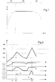
- the efficiency R of a converter as a function of its power output C is not constant.
- the efficiency is low for a low power supply level. It therefore appears necessary to avoid working in the low power zone Z1 for which the efficiency is low and favor the use of the converter in the Z2 rated areas and high power Z3 where the output is important.
- the figure 2 represents an example of an evolution of a conversion power C as a function of time t and the corresponding evolution of the respective supplied powers of the different converters in the case where a conversion device comprises four converters.
- the powers of the converters are represented by the graphs A, B, C, D.
- the first converter (graph A) is used up to a first power threshold S1 (corresponding to the power maximum of the first converter) reaches at time t1.
- the second converter (graph B) is also used up to a second threshold S2 (corresponding to the sum of the maximum powers of the first and the second converter) reached at time t2.
- thresholds S3 and S4 are defined for the third and fourth converters (graphs C and D).
- the four converters are used and then the conversion power decreases.
- the conversion power of the fourth converter is then decreased, then the conversion power of the third converter is decreased, and so on if the conversion power continues to decrease.
- the object of the present invention is therefore to propose a method for distributing the total conversion power between the converters of a conversion device with multiple converters making it possible to obtain an almost uniform use of the different converters.
- the object of the invention is further to provide a simple method without resorting to complex implementation means.
- the first predetermined power threshold corresponds to the maximum power level of the converter.
- the converters are reversible, the energy conversion being able to be done from the first to the second entity and from the second to the first entity.
- the first entity is a voltage source and the second entity is a device for powering an electric motor.
- the energy conversion device comprises four converters.
- a distribution of the power of the converters is made as a function of the performance characteristics of the converters.
- a permanent permutation permutation permutation of the converters according to the periodic sequence is controlled.
- the permanent progressive permutation speed is determined according to the thermal time constant of the converters.
- the permanent progressive permutation rate of a first predetermined speed value is increased when the conversion efficiency is lower than a first predetermined yield value.
- the permanent progressive permutation rate of a second predetermined speed value is reduced when the conversion efficiency is greater than a second predetermined yield value.
- said at least two converters correspond to at least two portions of a ring, the portions being proportional to a predetermined power value of their respective converter, the set of at least two portions forming the complete ring;
- the total power of the conversion device corresponds to an arc of the ring between the positions of a first and a second movable sliders along the ring; and in which the power distribution between the converters is defined by the positions of the first and second movable cursors along the ring.
- the positions of the portions of the ring can be rotated around the center of the ring, the displacement of the portions corresponding to a change in the power distribution between the different converters.
- the rotational displacement of the portions is a function of the efficiency characteristics of the converters.
- the rotational displacement of the portions is made permanently.
- the speed of the rotational displacement of the portions is a function of the thermal time constant of the converters.
- the rotational speed of the portions is increased by a first predefined speed value when the conversion efficiency of the conversion device is lower than a first predefined efficiency value.
- the speed of the rotational displacement of the portions is reduced by a second predefined speed value when the conversion efficiency of the conversion device is greater than a second predefined efficiency value.
- the invention further relates to a device for converting energy between a first and a second electrical entity, the energy conversion device comprising at least two converters characterized in that it also comprises a processing unit configured to implement a power distribution method according to the invention.
- the switches of the converters comprise a transistor connected in parallel with a diode.
- Embodiments of the present invention relate to the distribution of the total conversion power between the converters of a multi-converter energy conversion device, i.e. comprising a plurality of converters.
- the conversion device converts the received energy in a first form of a first electrical entity into a second form of energy transmitted to a second electrical entity.
- the first electrical entity is for example a voltage source such as accumulation means.
- the second electrical entity is for example a device for supplying an electric motor for driving a motor vehicle, such as an electrical control circuit of an electric motor.
- the two forms of energy are two DC voltages respectively having a first and a second amplitude.
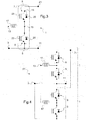
- the switches 9 consist of a transistor 23, generally of the IGBT type, connected in parallel with a diode 25, which makes it possible to obtain a reversible converter.
- the conversion can be done as well from the input terminals 3 and 13 to the output terminals 11 and 21 as the opposite.
- the converter corresponds to a boost circuit.
- the converter corresponds to a step-down circuit.
- the conversion device 27 thus comprises two output terminals 11 and 21 and two input terminals 3 and 13 as in the case of a single converter.
- any number of converters 1 can be connected in parallel.
- the converters 1 thus form a conversion device 27.
- the total power of the conversion device 27 is equal to the sum of the conversion powers of the converters 1.
- the paralleling of the converters 1 makes it possible to use certain converters 1 while the others are deactivated. For example, if there is a small total power of conversion, some converters 1 can be disabled in order to save energy and thus optimize the overall efficiency of the conversion device 27. Thus, when a converter is no longer requested (ie its power conversion is zero), it is disabled so that its power consumed is zero.
- the embodiments of the present invention describe the application, by a processing unit, of a "Rolling" or permutation concerning the use of different converters.
- each converter 1 corresponds a term in a periodic sequence of period n.
- the period n of the periodic sequence is the number of converters 1 in the conversion device 27.
- an initialization process designates, in a predefined or random manner, a converter as being active.
- the designated converter begins to provide the power of the converter device 27.
- the power distribution then applies as follows.
- the increase is applied to the last activated converter 1 among those that are active.
- the conversion power of the last activated converter 1 increases in correspondence with the increase of the total power of the conversion device 27.
- the increase of the total power of the converter device 27 conversion 27 is applied to the next converter 1 in the periodic sequence. If it is inactive, the next converter 1 in the periodic sequence is activated.
- the values of the first predetermined thresholds are defined so as to optimize the efficiency of the converters.
- the first predetermined threshold of a converter 1 corresponds to the maximum power level that can be provided by the converter.
- the conversion device 27 provides a maximum power when the set of converters 1 are activated at a power level equal to their respective predetermined thresholds.
- a power of cumulative conversion in time since its activation that is to say the energy supplied by the converter since its activation.
- the next converter is activated according to the periodic sequence.
- this power will accumulate at the conversion power of the newly activated converter (in the event of a reduction in the total conversion power of the conversion device, this power reduction will apply to converter power turned on first among active converters).
- This second predetermined threshold is, for example, determined from the constant thermal time of the converter. Thus, excessive heating of the converter 1 is avoided.
- the power distribution can be represented in a simple way using a geometric ring called in the following power ring.
- a representation of such a ring 29 is given on the figure 5 in the case of four converters of the same power connected in parallel.
- the different converters correspond to a portion of the ring 29.
- the set of portions corresponds to the complete ring 29.
- the portions are proportional to the first power threshold of the respective converters.
- the four converters 1 have the same predetermined first threshold value, so that the different portions are of equal size.
- the first power threshold corresponds to the maximum power that can be provided by a converter.
- each converter has a power of 10kW
- a quarter of a ring equals 10kW and the complete ring corresponds to 40kW
- the power is 15ka, only two converters are needed and the other two can be deactivated .
- the power ring 29 is divided into four portions delimited by a vertical axis ⁇ and a horizontal axis ⁇ .
- the portions are ring quarters denoted respectively C1, C2, C3 and C4.
- the corresponding converters will also be designated C1, C2, C3 and C4.
- the ring 29 comprises a first 31 and a second 33 movable sliders along the ring 29 and defining the power distribution between the four converters.
- the total power of the conversion device 27 corresponds to an arc 100 of the ring 29 between the positions of the first 31 and second 33 movable cursors along the ring 29.
- the positions of the first 31 and the second 33 movable cursors are defined so that when the total power of the conversion device 27 increases, the first movable cursor 31 moves in a predefined direction along the ring 29, so that proportional to the power increase.
- the second movable cursor 33 moves in the same predefined direction along the ring 29 in proportion to the decrease in power.
- the positions of the sliders 31, 33 define the power distribution of the converters 1 of the conversion device 27.
- the predefined direction is clockwise.
- an example of evolution of the distribution of the power over time will now be described in relation to the figure 6 .
- the figure 6 has two parts (a), (b).
- the upper part a) represents the evolution of the total power of the conversion device 27 as a function of time t.
- the lower part b) represents the evolution of the corresponding positions of the first 31 and the second 33 cursors along the ring 29.
- the two sliders 31 and 33 are positioned at the same place on the ring 29, at an intermediate point between two portions of the ring 29.
- the two sliders 31 and 33 are positioned at the location P0 if the converter C1 was designated during the initialization process.
- the first cursor 31 Just after the time t0, the total power of the device 27 increases to a first power level L1, the first cursor 31 then moves along the ring 29 over a length proportional to the first power level L1 to reach the position P1.
- the path of the first cursor 31 is entirely comprised in the portion of the converter C1. The power increase is therefore supported only by the first converter C1 so that only this first converter is active. Since the power is constant between the times t0 and t1, the first cursor 31 remains at the position P1.
- the total power of the device 27 increases to a second power level L2.
- the first slider 31 is moved along the ring 29 by a length proportional to the power increase L2-L1 of the device 27.
- the first slider 31 reaches the position P2 which is on the portion corresponding to the converter C2.
- the power increase L2-L1 of the device 27 is therefore supported by the first converter C1 and then by the second converter C2.
- the two converters C1, C2 are active.
- the power level of the device 27 decreases to the level L3.
- the second slider 33 is moved along the ring 29 over a length proportional to the power decrease L2-L3.
- the second cursor 33 moves from the position P0 to the position P3.
- the positions P0 and P3 are on the portion corresponding to the converter C1.
- the power reduction is therefore applied to the first converter C1 (which corresponds to the converter that has been activated first among the active converters).
- the two converters C1, C2 are active.
- the power level of the device 27 returns to a level L2.
- the first slider 31 is moved along the ring 29 over a length proportional to the power increase L2-L3.
- the first cursor 31 is moved from the position P3 to the position P4 which is on the portion corresponding to the converter C3.
- the power increase L2-L3 of the device 27 is therefore supported by the second converter C2 and then by the third converter C3.
- the three converters C1, C2, C3 are active.
- the power level decreases to a level L4.
- the second slider 33 is moved along the ring 29 over a length proportional to the power decrease L2-L4.
- the second cursor 33 is moved from the position P3 to the position P5 which is on the portion corresponding to the converter C3.
- the first converter C1 and the second converter C2 are inactive; only the converter C3 is active.
- the conversion device 27 is reversible and can thus operate in both directions, from a first to a second electrical entity or from the second to the first electrical entity.
- the first direction of conversion corresponds to the power supply of the motor.
- motor by the accumulation means while the opposite direction corresponds to a regenerative braking for recharging the accumulation means.
- the power distribution between the different converters is then the same way in both directions of power transfer.
- the conversion power in the opposite direction can be considered as a "negative" power.
- a negative power corresponds to a transfer of power from the second to the first electrical entity.
- the movements of the first 31 and second 33 cursors are identical to those described above.
- the figure 7 corresponds to the figure 6 to which a conversion cycle corresponding to the time interval between t5 and t6 has been added. This cycle corresponds to a cycle where the total power of the conversion device 27 is negative and corresponds to a level L5.
- the total power of the conversion device 27 becomes negative, indicating that the power transfer is from the second entity to the first entity.
- the total conversion power decreases to an L5 level.
- the second cursor 33 then moves from the position P5 to the position P6.
- the second cursor 33 is found "in front" of the first cursor 31, the portion located “between” the two sliders 33 and 31 corresponding to the "negative" power.
- the use of the two sliders 31 and 33 makes it possible to manage the power distribution in the two directions of conversion.
- the conversion powers designated by the reference 2 correspond to a low efficiency of the converter 1 as described in the zone Z1 of the figure 1 .
- a distribution of the total power of the conversion device 27 is made so as to optimize the conversion efficiency. between converters 1.
- the present embodiment consists in optimizing the distribution of partially used converters 1, that is, the converter 1 having been activated last and the converter 1 having been activated first among the active converters 1 (the other converters being used at full power or inactive).
- such a power distribution is represented by a rotational displacement of the portions of the power ring 29.
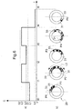
- the figure 8 represents three configurations of the power ring 29, previously described on the figure 5 , corresponding to three steps or instants of the realization of such an optimization.
- the first part of figure 8 represents an example of power distribution for which a first converter C1 is used at full power and a second converter C2 is used at low power (which corresponds to a low power efficiency of the converter C2).
- the power of the conversion device 27 remains constant over time.
- Power transfer is carried out from the first converter C1 to the second converter C2.
- the transfer is represented at the level of the ring 29 by a rotation of the portions around the center of the ring 29.
- Part (b) of the figure 8 represents an intermediate step of such a transfer of power. It should be noted that the power transfer can also be done to the converter C4. In this case the rotation of the portions will be in the opposite direction. The portions are rotated to obtain a power distribution corresponding to an optimized yield.
- the optimized efficiency can, for example, be determined from a characteristic representing the efficiency of the converter 1 as a function of the conversion power, and established by the manufacturer of the conversion device 27 and stored in a memory of the conversion device 27 .
- the optimum distribution corresponds to an equal distribution of the total power of the conversion device 27 between the two converters C1 and C2 as represented by the position of the axes. on part (c) of the figure 8 .
- the application of this embodiment therefore makes it possible to permanently transfer the conversion power successively to all the converters 1. This transfer can be carried out when the total power of the conversion device 27 is constant or permanently regardless of the evolution of the total power of the conversion device 27.
- the power transfer can also be done to the previous converters.
- the power transfer is represented by a permanent rotational movement of the portions of the ring 29 (the direction of rotation then defines the direction of the transfer (to the previous converters or to the following converters) in the periodic suite).
- this rotational displacement of the portions of the ring 29 can be done periodically, the amplitude and the period of rotation then being predefined according to the characteristics and in particular the thermal time constant of the converters.
- the figure 9 represents the evolution of the power distribution over time at five different times during the application of this embodiment.
- the total power of the connection device 27 remains constant for five instants and the power transfer is to the previous converters 1 according to the periodic sequence.
- the total power of the conversion device 27 is entirely distributed over the first converter C1.
- part of the power has been transferred from the first converter C1 to the fourth converter C4.
- the power is equally distributed between the first converter C1 and the fourth converter C4.
- the power is completely distributed on the fourth converter C4.
- part of the power has been transferred from the fourth converter C4 to the third converter C3.
- the power is thus transferred permanently from one converter 1 to the next according to the periodic sequence so as to obtain an almost uniform use of converters 1 over time.
- a permanent permutation permutation (or transfer) of power from a converter 1 to the following has just been described but the speed of this permutation has not been mentioned.
- the permutation rate is determined as a function of the thermal time constant of the converters 1 so as to limit the heating of the converters 1.
- the figure 10 represents an example of evolution of the conversion power C and the temperature T of a converter 1 over time t in the case of intensive use (part a) and in the case of intermittent use (part b).
- the temperature increases gradually, but less rapidly than in part a) since the power is less, between t0 and t1, then continues to increase until t2 to reach a maximum temperature Tn at time t2 and then goes down again gradually when the power decreases.
- the temperature Tn obtained is lower than the temperature Tm since the full power is applied only for a limited time, which makes it possible to avoid overheating of the converters 1.
- the transfer speed is therefore determined with respect to this time constant to limit the warming up in an optimized way.
- the permutation rate is represented by the rotational speed of the portions around the center of the ring 29.
- the first and second predetermined speed values are established according to the characteristics of the converters 1 and in particular their thermal time constant.
- the first and second predetermined yield values are based on a characteristic representing the efficiency of the converters 1 as a function of the conversion power.
- the first and second performance values can be equal. It is the same for the first and second predetermined speed values.
- This modulation amounts to reducing the time spent on power distribution configurations for which the efficiency is not optimized and to increasing the time spent on power distribution configurations for which the efficiency is optimized.
- the variation of the permutation speed is represented by the variation of the speed of rotation of the portions around the ring 29.
- the embodiments of the present invention make it possible to use all the converters of the device in a substantially uniform manner over time. regardless of the total conversion power of the conversion device 27. Moreover, by performing a permanent permutation of power between the converters 1, the embodiments of the present invention make it possible to limit the heating at the level of the converters 1.
- the method also makes it possible to optimize the power distribution between the converters 1 while providing a continuous conversion power. Indeed, in the processes of the prior art, when the total conversion power is less than a threshold, one or more converters are deactivated and the output of the other converters is increased in order to improve the total efficiency of the device, at total power. of equal conversion. This results in a discontinuity in the total conversion power at least in the transient phase.
- the conversion device 27 does not see a sudden deactivation of its converters 1.
- the rotation of the portions of the ring 29 (or, equivalently, axes ⁇ , ⁇ separating the portions) makes it possible to improve the power distribution and the uniformity of use of the converters 1 when the total power conversion remains constant.
- the rotation of the portions of the ring 29 also allows a continuity of the total conversion power when the latter remains constant and that it is desired to alternate the use of the converters 1.
- the energy conversion device 27 may comprise a processing unit configured to implement the method according to the invention.
- the processing unit comprises a module integrating a representation of the geometric ring 29.
- the ring 29 can be stored in a memory in the form of several angular intervals each corresponding to a respective converter 1.
- the positions of the first 31 and second 33 cursors may correspond to respective angular values stored in a memory.
- the power distribution between the converters 1 can be represented by the ring 29 on a display unit to inform a user of the energy conversion device 27.
Landscapes
- Engineering & Computer Science (AREA)
- Power Engineering (AREA)
- Physics & Mathematics (AREA)
- Electromagnetism (AREA)
- General Physics & Mathematics (AREA)
- Radar, Positioning & Navigation (AREA)
- Automation & Control Theory (AREA)
- Dc-Dc Converters (AREA)
- Inverter Devices (AREA)
- Ac-Ac Conversion (AREA)
Applications Claiming Priority (1)
| Application Number | Priority Date | Filing Date | Title |
|---|---|---|---|
| FR1151536A FR2972085B1 (fr) | 2011-02-25 | 2011-02-25 | Dispositif de conversion d'energie et procede de repartition associe |
Publications (3)
| Publication Number | Publication Date |
|---|---|
| EP2493045A2 true EP2493045A2 (de) | 2012-08-29 |
| EP2493045A3 EP2493045A3 (de) | 2014-10-22 |
| EP2493045B1 EP2493045B1 (de) | 2019-10-02 |
Family
ID=45581794
Family Applications (1)
| Application Number | Title | Priority Date | Filing Date |
|---|---|---|---|
| EP12156187.2A Active EP2493045B1 (de) | 2011-02-25 | 2012-02-20 | Vorrichtung zur Energieumwandlung, und entsprechendes Verteilungsverfahren |
Country Status (7)
| Country | Link |
|---|---|
| US (2) | US9112380B2 (de) |
| EP (1) | EP2493045B1 (de) |
| JP (2) | JP6032902B2 (de) |
| KR (2) | KR101986321B1 (de) |
| CN (2) | CN106685189B (de) |
| BR (1) | BR102012004129A2 (de) |
| FR (1) | FR2972085B1 (de) |
Families Citing this family (8)
| Publication number | Priority date | Publication date | Assignee | Title |
|---|---|---|---|---|
| JPH0738657Y2 (ja) | 1988-05-31 | 1995-09-06 | 日産ディーゼル工業株式会社 | 内燃機関の燃焼装置 |
| FR2953996B1 (fr) | 2009-12-11 | 2012-01-20 | Centre Nat Rech Scient | Systeme de gestion electronique de cellules photovoltaiques fonction de la meteorologie |
| FR2953997B1 (fr) * | 2009-12-11 | 2012-01-20 | Centre Nat Rech Scient | Systeme de gestion electronique de cellules photovoltaiques avec seuils adaptes |
| KR102574467B1 (ko) * | 2018-06-22 | 2023-09-05 | 삼성전자주식회사 | 유선 또는 무선으로 수신되는 디지털 오디오 신호를 아날로그 오디오 신호로 변환하는 전자 장치, 방법 및 시스템 |
| CN112583251B (zh) * | 2019-09-30 | 2023-08-08 | 比亚迪股份有限公司 | 列车、双向dc-dc变换器及其控制方法、装置和系统 |
| CN113129559B (zh) * | 2019-12-31 | 2022-08-05 | 国创移动能源创新中心(江苏)有限公司 | 功率分配机器人的故障预警系统和方法 |
| US11735922B2 (en) * | 2020-08-28 | 2023-08-22 | Smart Wires Inc. | Temporal balancing of electrical stress on FACTS devices in FACTS based distributed impedance injection units |
| US11563379B2 (en) * | 2021-05-03 | 2023-01-24 | Advanced Energy Industries, Inc. | Phase current balancing for multiphase coupled inductor converter |
Family Cites Families (25)
| Publication number | Priority date | Publication date | Assignee | Title |
|---|---|---|---|---|
| US5905645A (en) * | 1996-12-02 | 1999-05-18 | Astec International Limited | Thermally aided power sharing of power supplies with or without an external current share line |
| JPH11127573A (ja) * | 1997-10-23 | 1999-05-11 | Mitsubishi Electric Corp | Dc/dcコンバータの並列運転装置 |
| JP3545203B2 (ja) * | 1998-05-22 | 2004-07-21 | 三洋電機株式会社 | インバータの運転方法及び電源システム |
| FR2783375B1 (fr) * | 1998-09-14 | 2000-12-29 | Valeo Electronique | Circuit de commutation, notamment pour generer des signaux de commande du type a impulsions a largeur modulee dans un vehicule automobile |
| DE10060429A1 (de) * | 1999-12-16 | 2001-07-12 | Caterpillar Inc | Verfahren und Vorrichtung zur Leistungsübertragung |
| JP2001263255A (ja) * | 2000-03-15 | 2001-09-26 | Sayama Seisakusho:Kk | ポンプのローテーション運転制御方法および装置 |
| JP3695379B2 (ja) * | 2001-10-02 | 2005-09-14 | 日産自動車株式会社 | 電源システム |
| US6625045B1 (en) * | 2001-12-28 | 2003-09-23 | Semtech Corporation | Multiphase modular power module employing star link topography |
| US20080129260A1 (en) * | 2006-12-04 | 2008-06-05 | Jaber Abu Qahouq | Current sharing for multiphase power conversion |
| US7646785B2 (en) * | 2006-12-21 | 2010-01-12 | Palo Alto Research Center Incorporated | Cyclical-transmission-schedule reservation technique |
| DE112007003408A5 (de) * | 2007-01-17 | 2009-12-24 | Siemens Aktiengesellschaft | Ansteuerung eines Phasenmodulzweiges eines Multilevel-Stromrichters |
| JP2008217520A (ja) * | 2007-03-06 | 2008-09-18 | Sharp Corp | スケジュール管理装置、スケジュール管理システム、スケジュール管理方法及びスケジュール管理プログラム |
| JP2008245348A (ja) * | 2007-03-26 | 2008-10-09 | Fujitsu Ten Ltd | 昇圧回路制御装置、及び昇圧回路制御方法 |
| US8319484B2 (en) * | 2007-12-12 | 2012-11-27 | Intersil Americas Inc. | Voltage regulator system and method for efficiency optimization using duty cycle measurements |
| JP4530066B2 (ja) * | 2008-03-12 | 2010-08-25 | 株式会社デンソー | 電力変換回路の制御装置、及び電力変換システム |
| JP5275688B2 (ja) * | 2008-06-04 | 2013-08-28 | 住友重機械工業株式会社 | コンバータ装置 |
| CN102067406B (zh) * | 2008-06-17 | 2013-07-31 | 西门子公司 | 具有自换向变流器的高压直流输电设备的调节方法 |
| JP5160371B2 (ja) * | 2008-10-17 | 2013-03-13 | 本田技研工業株式会社 | 交流電力供給装置及びその制御方法 |
| BRPI0921635A2 (pt) * | 2008-10-31 | 2016-01-05 | Optimum Energy Llc | sistemas e métodos para controlar a eficiência de consumo de energia |
| US7889525B2 (en) * | 2009-03-25 | 2011-02-15 | Intersil Americas Inc. | System and method for phase dropping and adding |
| EP2341605B1 (de) * | 2009-12-31 | 2018-03-07 | Nxp B.V. | Leistungsfaktorkorrekturstufe |
| FR2961972B1 (fr) * | 2010-06-25 | 2012-07-13 | Valeo Sys Controle Moteur Sas | Dispositif electrique d'entrainement d'un equipement mecanique et procede associe |
| US9331499B2 (en) * | 2010-08-18 | 2016-05-03 | Volterra Semiconductor LLC | System, method, module, and energy exchanger for optimizing output of series-connected photovoltaic and electrochemical devices |
| US8120935B2 (en) * | 2011-03-29 | 2012-02-21 | American Superconductor Corporation | Power converter with dual ring network control |
| US20120249101A1 (en) * | 2011-04-01 | 2012-10-04 | Akey David W | Consistently balanced thermal load dc-dc converter |
-
2011
- 2011-02-25 FR FR1151536A patent/FR2972085B1/fr active Active
-
2012
- 2012-02-20 EP EP12156187.2A patent/EP2493045B1/de active Active
- 2012-02-24 JP JP2012038328A patent/JP6032902B2/ja active Active
- 2012-02-24 BR BRBR102012004129-4A patent/BR102012004129A2/pt not_active Application Discontinuation
- 2012-02-24 US US13/404,672 patent/US9112380B2/en active Active
- 2012-02-27 CN CN201610634696.2A patent/CN106685189B/zh active Active
- 2012-02-27 CN CN201210147195.3A patent/CN102684456B/zh active Active
- 2012-02-27 KR KR1020120019800A patent/KR101986321B1/ko active Active
-
2015
- 2015-07-14 US US14/799,262 patent/US10884444B2/en active Active
-
2016
- 2016-10-25 JP JP2016208562A patent/JP6328206B2/ja active Active
-
2019
- 2019-05-29 KR KR1020190062906A patent/KR102128682B1/ko active Active
Non-Patent Citations (1)
| Title |
|---|
| None |
Also Published As
| Publication number | Publication date |
|---|---|
| US10884444B2 (en) | 2021-01-05 |
| US20150316948A1 (en) | 2015-11-05 |
| KR101986321B1 (ko) | 2019-06-07 |
| CN102684456B (zh) | 2016-08-31 |
| JP6328206B2 (ja) | 2018-05-23 |
| EP2493045A3 (de) | 2014-10-22 |
| FR2972085B1 (fr) | 2015-01-16 |
| KR20190062358A (ko) | 2019-06-05 |
| FR2972085A1 (fr) | 2012-08-31 |
| BR102012004129A2 (pt) | 2013-07-23 |
| JP2017017997A (ja) | 2017-01-19 |
| JP2012178970A (ja) | 2012-09-13 |
| CN106685189B (zh) | 2020-09-29 |
| JP6032902B2 (ja) | 2016-11-30 |
| CN102684456A (zh) | 2012-09-19 |
| EP2493045B1 (de) | 2019-10-02 |
| US20120217948A1 (en) | 2012-08-30 |
| KR20120098511A (ko) | 2012-09-05 |
| KR102128682B1 (ko) | 2020-06-30 |
| US9112380B2 (en) | 2015-08-18 |
| CN106685189A (zh) | 2017-05-17 |
Similar Documents
| Publication | Publication Date | Title |
|---|---|---|
| EP2493045B1 (de) | Vorrichtung zur Energieumwandlung, und entsprechendes Verteilungsverfahren | |
| EP2821279B1 (de) | Elektrisches Aufladesystem einer Vielzahl von elektrischen Fahrzeugen, und Verteilungsverfahren der elektrischen Leistung, die durch eine elektrische Stromversorgung eines solchen Systems geliefert wird | |
| EP1265336A2 (de) | Ausgleichverfahren für eine elektrische Batterie im diskontinuierlichen Lade-Modus und Batterieverwaltungssystem zur Durchführung des Verfahrens | |
| FR2943188A1 (fr) | Dispositif de charge rapide pour un vehicule electrique. | |
| EP2904687B1 (de) | Schaltung zur verwaltung des ladezustandes einer batterie | |
| EP0573832A1 (de) | Gerät zum Laden eines Wiederaufladbaren Akkumulators | |
| EP2753491B1 (de) | Verfahren und vorrichtung zum optimierten wiederaufladen einer elektrischen batterie | |
| EP1427092A1 (de) | Steuerungsverfahren für ein Schaltnetzteil mit einem einzelnen Induktor und mehreren Ausgängen, entsprechendes Schaltnetzteil, insbesondere für ein zellulares Mobiltelefon | |
| FR2893778A1 (fr) | Generateur a utiliser sur un vehicule | |
| FR3012399A1 (fr) | Systeme de charge de vehicule | |
| FR3067878B1 (fr) | Procede de charge de batteries pour un aeronef et systeme de stockage d'energie electrique | |
| FR2985115A1 (fr) | Commande d'une charge inductive avec mecanisme de reduction de courant sensible a la temperature | |
| WO2012101375A2 (fr) | Dispositif et procede d'equilibrage de l'etat de charge d'une source d'energie a stockage electrochimique composee de plusieurs cellules de stockage d'energie | |
| WO2012107190A1 (fr) | Commande a hysteresis d'un dispositif electronique par un signal module en largeur d'impulsion | |
| WO2018172671A1 (fr) | Procédé de commande d'un convertisseur ac/dc multiniveaux | |
| FR2937197A1 (fr) | Appareil de commande pour un alternateur automobile | |
| EP2871917B1 (de) | Stromversorgungssystem eines oder mehrerer Beleuchtungsmodule mit Leuchtdioden, entsprechende Beleuchtungsanlage und entsprechendes Stromversorgungsverfahren | |
| FR2855808A1 (fr) | Equipement electro-hydraulique de direction assistee | |
| EP3562703B1 (de) | Elektrisch angetriebenes transportsystem | |
| EP2908605A1 (de) | Elektronische Vorrichtung zur Stromversorgung einer Elektrolumineszenzdiode | |
| EP3667898A1 (de) | Steuerung einer anzahl von aktiven leistungszellen eines drehzahlreglers | |
| WO2012140363A1 (fr) | Dispositif et procede d'equilibrage de cellules d'une batterie | |
| EP4447302A1 (de) | Doppelbrücken-schaltwandlersteuerung | |
| EP2203971B1 (de) | Verfahren zur steuerung eines schaltnetzteils und entsprechendes netzteil | |
| FR3150745A1 (fr) | Procede pour commander un moteur electrique sans couple provoquant un rechaufement d’une batterie |
Legal Events
| Date | Code | Title | Description |
|---|---|---|---|
| PUAI | Public reference made under article 153(3) epc to a published international application that has entered the european phase |
Free format text: ORIGINAL CODE: 0009012 |
|
| AK | Designated contracting states |
Kind code of ref document: A2 Designated state(s): AL AT BE BG CH CY CZ DE DK EE ES FI FR GB GR HR HU IE IS IT LI LT LU LV MC MK MT NL NO PL PT RO RS SE SI SK SM TR |
|
| AX | Request for extension of the european patent |
Extension state: BA ME |
|
| PUAL | Search report despatched |
Free format text: ORIGINAL CODE: 0009013 |
|
| AK | Designated contracting states |
Kind code of ref document: A3 Designated state(s): AL AT BE BG CH CY CZ DE DK EE ES FI FR GB GR HR HU IE IS IT LI LT LU LV MC MK MT NL NO PL PT RO RS SE SI SK SM TR |
|
| AX | Request for extension of the european patent |
Extension state: BA ME |
|
| RIC1 | Information provided on ipc code assigned before grant |
Ipc: H02M 3/28 20060101ALI20140917BHEP Ipc: H02M 7/493 20070101ALI20140917BHEP Ipc: H02J 1/10 20060101AFI20140917BHEP |
|
| 17P | Request for examination filed |
Effective date: 20150414 |
|
| RBV | Designated contracting states (corrected) |
Designated state(s): AL AT BE BG CH CY CZ DE DK EE ES FI FR GB GR HR HU IE IS IT LI LT LU LV MC MK MT NL NO PL PT RO RS SE SI SK SM TR |
|
| STAA | Information on the status of an ep patent application or granted ep patent |
Free format text: STATUS: EXAMINATION IS IN PROGRESS |
|
| 17Q | First examination report despatched |
Effective date: 20181206 |
|
| REG | Reference to a national code |
Ref country code: DE Ref legal event code: R079 Ref document number: 602012064439 Country of ref document: DE Free format text: PREVIOUS MAIN CLASS: H02J0001100000 Ipc: H02J0003460000 |
|
| GRAP | Despatch of communication of intention to grant a patent |
Free format text: ORIGINAL CODE: EPIDOSNIGR1 |
|
| STAA | Information on the status of an ep patent application or granted ep patent |
Free format text: STATUS: GRANT OF PATENT IS INTENDED |
|
| RIC1 | Information provided on ipc code assigned before grant |
Ipc: H02M 3/28 20060101ALI20190416BHEP Ipc: H02J 3/46 20060101AFI20190416BHEP Ipc: H02J 1/10 20060101ALI20190416BHEP |
|
| INTG | Intention to grant announced |
Effective date: 20190513 |
|
| GRAS | Grant fee paid |
Free format text: ORIGINAL CODE: EPIDOSNIGR3 |
|
| GRAA | (expected) grant |
Free format text: ORIGINAL CODE: 0009210 |
|
| STAA | Information on the status of an ep patent application or granted ep patent |
Free format text: STATUS: THE PATENT HAS BEEN GRANTED |
|
| AK | Designated contracting states |
Kind code of ref document: B1 Designated state(s): AL AT BE BG CH CY CZ DE DK EE ES FI FR GB GR HR HU IE IS IT LI LT LU LV MC MK MT NL NO PL PT RO RS SE SI SK SM TR |
|
| REG | Reference to a national code |
Ref country code: GB Ref legal event code: FG4D Free format text: NOT ENGLISH |
|
| REG | Reference to a national code |
Ref country code: CH Ref legal event code: EP Ref country code: AT Ref legal event code: REF Ref document number: 1187274 Country of ref document: AT Kind code of ref document: T Effective date: 20191015 |
|
| REG | Reference to a national code |
Ref country code: IE Ref legal event code: FG4D Free format text: LANGUAGE OF EP DOCUMENT: FRENCH |
|
| REG | Reference to a national code |
Ref country code: DE Ref legal event code: R096 Ref document number: 602012064439 Country of ref document: DE |
|
| REG | Reference to a national code |
Ref country code: NL Ref legal event code: MP Effective date: 20191002 |
|
| REG | Reference to a national code |
Ref country code: LT Ref legal event code: MG4D |
|
| REG | Reference to a national code |
Ref country code: AT Ref legal event code: MK05 Ref document number: 1187274 Country of ref document: AT Kind code of ref document: T Effective date: 20191002 |
|
| PG25 | Lapsed in a contracting state [announced via postgrant information from national office to epo] |
Ref country code: LT Free format text: LAPSE BECAUSE OF FAILURE TO SUBMIT A TRANSLATION OF THE DESCRIPTION OR TO PAY THE FEE WITHIN THE PRESCRIBED TIME-LIMIT Effective date: 20191002 Ref country code: SE Free format text: LAPSE BECAUSE OF FAILURE TO SUBMIT A TRANSLATION OF THE DESCRIPTION OR TO PAY THE FEE WITHIN THE PRESCRIBED TIME-LIMIT Effective date: 20191002 Ref country code: LV Free format text: LAPSE BECAUSE OF FAILURE TO SUBMIT A TRANSLATION OF THE DESCRIPTION OR TO PAY THE FEE WITHIN THE PRESCRIBED TIME-LIMIT Effective date: 20191002 Ref country code: NL Free format text: LAPSE BECAUSE OF FAILURE TO SUBMIT A TRANSLATION OF THE DESCRIPTION OR TO PAY THE FEE WITHIN THE PRESCRIBED TIME-LIMIT Effective date: 20191002 Ref country code: ES Free format text: LAPSE BECAUSE OF FAILURE TO SUBMIT A TRANSLATION OF THE DESCRIPTION OR TO PAY THE FEE WITHIN THE PRESCRIBED TIME-LIMIT Effective date: 20191002 Ref country code: NO Free format text: LAPSE BECAUSE OF FAILURE TO SUBMIT A TRANSLATION OF THE DESCRIPTION OR TO PAY THE FEE WITHIN THE PRESCRIBED TIME-LIMIT Effective date: 20200102 Ref country code: GR Free format text: LAPSE BECAUSE OF FAILURE TO SUBMIT A TRANSLATION OF THE DESCRIPTION OR TO PAY THE FEE WITHIN THE PRESCRIBED TIME-LIMIT Effective date: 20200103 Ref country code: PL Free format text: LAPSE BECAUSE OF FAILURE TO SUBMIT A TRANSLATION OF THE DESCRIPTION OR TO PAY THE FEE WITHIN THE PRESCRIBED TIME-LIMIT Effective date: 20191002 Ref country code: BG Free format text: LAPSE BECAUSE OF FAILURE TO SUBMIT A TRANSLATION OF THE DESCRIPTION OR TO PAY THE FEE WITHIN THE PRESCRIBED TIME-LIMIT Effective date: 20200102 Ref country code: FI Free format text: LAPSE BECAUSE OF FAILURE TO SUBMIT A TRANSLATION OF THE DESCRIPTION OR TO PAY THE FEE WITHIN THE PRESCRIBED TIME-LIMIT Effective date: 20191002 Ref country code: PT Free format text: LAPSE BECAUSE OF FAILURE TO SUBMIT A TRANSLATION OF THE DESCRIPTION OR TO PAY THE FEE WITHIN THE PRESCRIBED TIME-LIMIT Effective date: 20200203 Ref country code: AT Free format text: LAPSE BECAUSE OF FAILURE TO SUBMIT A TRANSLATION OF THE DESCRIPTION OR TO PAY THE FEE WITHIN THE PRESCRIBED TIME-LIMIT Effective date: 20191002 |
|
| PG25 | Lapsed in a contracting state [announced via postgrant information from national office to epo] |
Ref country code: RS Free format text: LAPSE BECAUSE OF FAILURE TO SUBMIT A TRANSLATION OF THE DESCRIPTION OR TO PAY THE FEE WITHIN THE PRESCRIBED TIME-LIMIT Effective date: 20191002 Ref country code: CZ Free format text: LAPSE BECAUSE OF FAILURE TO SUBMIT A TRANSLATION OF THE DESCRIPTION OR TO PAY THE FEE WITHIN THE PRESCRIBED TIME-LIMIT Effective date: 20191002 Ref country code: IS Free format text: LAPSE BECAUSE OF FAILURE TO SUBMIT A TRANSLATION OF THE DESCRIPTION OR TO PAY THE FEE WITHIN THE PRESCRIBED TIME-LIMIT Effective date: 20200224 Ref country code: HR Free format text: LAPSE BECAUSE OF FAILURE TO SUBMIT A TRANSLATION OF THE DESCRIPTION OR TO PAY THE FEE WITHIN THE PRESCRIBED TIME-LIMIT Effective date: 20191002 |
|
| PG25 | Lapsed in a contracting state [announced via postgrant information from national office to epo] |
Ref country code: AL Free format text: LAPSE BECAUSE OF FAILURE TO SUBMIT A TRANSLATION OF THE DESCRIPTION OR TO PAY THE FEE WITHIN THE PRESCRIBED TIME-LIMIT Effective date: 20191002 |
|
| REG | Reference to a national code |
Ref country code: DE Ref legal event code: R097 Ref document number: 602012064439 Country of ref document: DE |
|
| PG2D | Information on lapse in contracting state deleted |
Ref country code: IS |
|
| PG25 | Lapsed in a contracting state [announced via postgrant information from national office to epo] |
Ref country code: DK Free format text: LAPSE BECAUSE OF FAILURE TO SUBMIT A TRANSLATION OF THE DESCRIPTION OR TO PAY THE FEE WITHIN THE PRESCRIBED TIME-LIMIT Effective date: 20191002 Ref country code: EE Free format text: LAPSE BECAUSE OF FAILURE TO SUBMIT A TRANSLATION OF THE DESCRIPTION OR TO PAY THE FEE WITHIN THE PRESCRIBED TIME-LIMIT Effective date: 20191002 Ref country code: RO Free format text: LAPSE BECAUSE OF FAILURE TO SUBMIT A TRANSLATION OF THE DESCRIPTION OR TO PAY THE FEE WITHIN THE PRESCRIBED TIME-LIMIT Effective date: 20191002 Ref country code: IS Free format text: LAPSE BECAUSE OF FAILURE TO SUBMIT A TRANSLATION OF THE DESCRIPTION OR TO PAY THE FEE WITHIN THE PRESCRIBED TIME-LIMIT Effective date: 20200202 |
|
| PLBE | No opposition filed within time limit |
Free format text: ORIGINAL CODE: 0009261 |
|
| STAA | Information on the status of an ep patent application or granted ep patent |
Free format text: STATUS: NO OPPOSITION FILED WITHIN TIME LIMIT |
|
| PG25 | Lapsed in a contracting state [announced via postgrant information from national office to epo] |
Ref country code: SK Free format text: LAPSE BECAUSE OF FAILURE TO SUBMIT A TRANSLATION OF THE DESCRIPTION OR TO PAY THE FEE WITHIN THE PRESCRIBED TIME-LIMIT Effective date: 20191002 Ref country code: SM Free format text: LAPSE BECAUSE OF FAILURE TO SUBMIT A TRANSLATION OF THE DESCRIPTION OR TO PAY THE FEE WITHIN THE PRESCRIBED TIME-LIMIT Effective date: 20191002 Ref country code: IT Free format text: LAPSE BECAUSE OF FAILURE TO SUBMIT A TRANSLATION OF THE DESCRIPTION OR TO PAY THE FEE WITHIN THE PRESCRIBED TIME-LIMIT Effective date: 20191002 |
|
| 26N | No opposition filed |
Effective date: 20200703 |
|
| REG | Reference to a national code |
Ref country code: CH Ref legal event code: PL |
|
| REG | Reference to a national code |
Ref country code: BE Ref legal event code: MM Effective date: 20200229 |
|
| PG25 | Lapsed in a contracting state [announced via postgrant information from national office to epo] |
Ref country code: LU Free format text: LAPSE BECAUSE OF NON-PAYMENT OF DUE FEES Effective date: 20200220 Ref country code: MC Free format text: LAPSE BECAUSE OF FAILURE TO SUBMIT A TRANSLATION OF THE DESCRIPTION OR TO PAY THE FEE WITHIN THE PRESCRIBED TIME-LIMIT Effective date: 20191002 |
|
| PG25 | Lapsed in a contracting state [announced via postgrant information from national office to epo] |
Ref country code: CH Free format text: LAPSE BECAUSE OF NON-PAYMENT OF DUE FEES Effective date: 20200229 Ref country code: LI Free format text: LAPSE BECAUSE OF NON-PAYMENT OF DUE FEES Effective date: 20200229 Ref country code: SI Free format text: LAPSE BECAUSE OF FAILURE TO SUBMIT A TRANSLATION OF THE DESCRIPTION OR TO PAY THE FEE WITHIN THE PRESCRIBED TIME-LIMIT Effective date: 20191002 |
|
| PG25 | Lapsed in a contracting state [announced via postgrant information from national office to epo] |
Ref country code: IE Free format text: LAPSE BECAUSE OF NON-PAYMENT OF DUE FEES Effective date: 20200220 |
|
| PG25 | Lapsed in a contracting state [announced via postgrant information from national office to epo] |
Ref country code: BE Free format text: LAPSE BECAUSE OF NON-PAYMENT OF DUE FEES Effective date: 20200229 |
|
| PG25 | Lapsed in a contracting state [announced via postgrant information from national office to epo] |
Ref country code: TR Free format text: LAPSE BECAUSE OF FAILURE TO SUBMIT A TRANSLATION OF THE DESCRIPTION OR TO PAY THE FEE WITHIN THE PRESCRIBED TIME-LIMIT Effective date: 20191002 Ref country code: MT Free format text: LAPSE BECAUSE OF FAILURE TO SUBMIT A TRANSLATION OF THE DESCRIPTION OR TO PAY THE FEE WITHIN THE PRESCRIBED TIME-LIMIT Effective date: 20191002 Ref country code: CY Free format text: LAPSE BECAUSE OF FAILURE TO SUBMIT A TRANSLATION OF THE DESCRIPTION OR TO PAY THE FEE WITHIN THE PRESCRIBED TIME-LIMIT Effective date: 20191002 |
|
| PG25 | Lapsed in a contracting state [announced via postgrant information from national office to epo] |
Ref country code: MK Free format text: LAPSE BECAUSE OF FAILURE TO SUBMIT A TRANSLATION OF THE DESCRIPTION OR TO PAY THE FEE WITHIN THE PRESCRIBED TIME-LIMIT Effective date: 20191002 |
|
| P01 | Opt-out of the competence of the unified patent court (upc) registered |
Effective date: 20230528 |
|
| PGFP | Annual fee paid to national office [announced via postgrant information from national office to epo] |
Ref country code: GB Payment date: 20260219 Year of fee payment: 15 |
|
| PGFP | Annual fee paid to national office [announced via postgrant information from national office to epo] |
Ref country code: DE Payment date: 20260206 Year of fee payment: 15 |
|
| PGFP | Annual fee paid to national office [announced via postgrant information from national office to epo] |
Ref country code: FR Payment date: 20260227 Year of fee payment: 15 |