EP2492459B1 - Régulateur de phase d'arbres doté d'un dispositif de verrouillage amélioré - Google Patents
Régulateur de phase d'arbres doté d'un dispositif de verrouillage amélioré Download PDFInfo
- Publication number
- EP2492459B1 EP2492459B1 EP12156574.1A EP12156574A EP2492459B1 EP 2492459 B1 EP2492459 B1 EP 2492459B1 EP 12156574 A EP12156574 A EP 12156574A EP 2492459 B1 EP2492459 B1 EP 2492459B1
- Authority
- EP
- European Patent Office
- Prior art keywords
- pressure
- rotor
- latching
- pin
- locking
- Prior art date
- Legal status (The legal status is an assumption and is not a legal conclusion. Google has not performed a legal analysis and makes no representation as to the accuracy of the status listed.)
- Not-in-force
Links
- 239000012530 fluid Substances 0.000 claims description 126
- 238000002485 combustion reaction Methods 0.000 claims description 59
- 230000009191 jumping Effects 0.000 claims 1
- 238000003860 storage Methods 0.000 description 115
- RDYMFSUJUZBWLH-UHFFFAOYSA-N endosulfan Chemical compound C12COS(=O)OCC2C2(Cl)C(Cl)=C(Cl)C1(Cl)C2(Cl)Cl RDYMFSUJUZBWLH-UHFFFAOYSA-N 0.000 description 91
- 230000008878 coupling Effects 0.000 description 19
- 238000010168 coupling process Methods 0.000 description 19
- 238000005859 coupling reaction Methods 0.000 description 19
- 230000000903 blocking effect Effects 0.000 description 18
- 238000011144 upstream manufacturing Methods 0.000 description 15
- 238000007789 sealing Methods 0.000 description 14
- 239000010687 lubricating oil Substances 0.000 description 12
- 230000008901 benefit Effects 0.000 description 9
- 238000007639 printing Methods 0.000 description 9
- 230000002093 peripheral effect Effects 0.000 description 7
- 230000010349 pulsation Effects 0.000 description 7
- 238000013461 design Methods 0.000 description 6
- 238000011161 development Methods 0.000 description 6
- 238000004519 manufacturing process Methods 0.000 description 6
- 238000005259 measurement Methods 0.000 description 6
- 230000009467 reduction Effects 0.000 description 5
- 241001295925 Gegenes Species 0.000 description 4
- XAGFODPZIPBFFR-UHFFFAOYSA-N aluminium Chemical compound [Al] XAGFODPZIPBFFR-UHFFFAOYSA-N 0.000 description 4
- 229910052782 aluminium Inorganic materials 0.000 description 4
- 230000005540 biological transmission Effects 0.000 description 4
- 230000008859 change Effects 0.000 description 4
- 230000002349 favourable effect Effects 0.000 description 4
- 230000006870 function Effects 0.000 description 4
- MUBZPKHOEPUJKR-UHFFFAOYSA-N Oxalic acid Chemical compound OC(=O)C(O)=O MUBZPKHOEPUJKR-UHFFFAOYSA-N 0.000 description 3
- 238000005304 joining Methods 0.000 description 3
- 239000000463 material Substances 0.000 description 3
- 230000000452 restraining effect Effects 0.000 description 3
- QAOWNCQODCNURD-UHFFFAOYSA-N Sulfuric acid Chemical compound OS(O)(=O)=O QAOWNCQODCNURD-UHFFFAOYSA-N 0.000 description 2
- 239000000956 alloy Substances 0.000 description 2
- 229910045601 alloy Inorganic materials 0.000 description 2
- 230000006399 behavior Effects 0.000 description 2
- 230000009286 beneficial effect Effects 0.000 description 2
- 230000015572 biosynthetic process Effects 0.000 description 2
- 238000006073 displacement reaction Methods 0.000 description 2
- 230000000694 effects Effects 0.000 description 2
- 239000003344 environmental pollutant Substances 0.000 description 2
- 239000000446 fuel Substances 0.000 description 2
- 230000003993 interaction Effects 0.000 description 2
- 230000001050 lubricating effect Effects 0.000 description 2
- 238000000034 method Methods 0.000 description 2
- 231100000719 pollutant Toxicity 0.000 description 2
- 230000008569 process Effects 0.000 description 2
- 230000002441 reversible effect Effects 0.000 description 2
- 238000000926 separation method Methods 0.000 description 2
- 239000012791 sliding layer Substances 0.000 description 2
- 238000012360 testing method Methods 0.000 description 2
- 230000007704 transition Effects 0.000 description 2
- 230000004308 accommodation Effects 0.000 description 1
- 230000001154 acute effect Effects 0.000 description 1
- 239000000654 additive Substances 0.000 description 1
- 238000007743 anodising Methods 0.000 description 1
- TZCXTZWJZNENPQ-UHFFFAOYSA-L barium sulfate Chemical compound [Ba+2].[O-]S([O-])(=O)=O TZCXTZWJZNENPQ-UHFFFAOYSA-L 0.000 description 1
- 238000010009 beating Methods 0.000 description 1
- 238000004891 communication Methods 0.000 description 1
- 230000001276 controlling effect Effects 0.000 description 1
- 230000007423 decrease Effects 0.000 description 1
- 238000009795 derivation Methods 0.000 description 1
- 238000007598 dipping method Methods 0.000 description 1
- 238000007599 discharging Methods 0.000 description 1
- 238000009826 distribution Methods 0.000 description 1
- 239000003792 electrolyte Substances 0.000 description 1
- 238000005516 engineering process Methods 0.000 description 1
- 238000005429 filling process Methods 0.000 description 1
- 238000007654 immersion Methods 0.000 description 1
- 230000006872 improvement Effects 0.000 description 1
- 239000010410 layer Substances 0.000 description 1
- 239000012528 membrane Substances 0.000 description 1
- 239000000203 mixture Substances 0.000 description 1
- 239000003921 oil Substances 0.000 description 1
- 235000006408 oxalic acid Nutrition 0.000 description 1
- 230000035515 penetration Effects 0.000 description 1
- 230000036316 preload Effects 0.000 description 1
- 230000001105 regulatory effect Effects 0.000 description 1
- 230000004044 response Effects 0.000 description 1
- 230000000979 retarding effect Effects 0.000 description 1
- 238000010008 shearing Methods 0.000 description 1
- 238000012546 transfer Methods 0.000 description 1
Images


Classifications
-
- F—MECHANICAL ENGINEERING; LIGHTING; HEATING; WEAPONS; BLASTING
- F01—MACHINES OR ENGINES IN GENERAL; ENGINE PLANTS IN GENERAL; STEAM ENGINES
- F01L—CYCLICALLY OPERATING VALVES FOR MACHINES OR ENGINES
- F01L1/00—Valve-gear or valve arrangements, e.g. lift-valve gear
- F01L1/34—Valve-gear or valve arrangements, e.g. lift-valve gear characterised by the provision of means for changing the timing of the valves without changing the duration of opening and without affecting the magnitude of the valve lift
- F01L1/344—Valve-gear or valve arrangements, e.g. lift-valve gear characterised by the provision of means for changing the timing of the valves without changing the duration of opening and without affecting the magnitude of the valve lift changing the angular relationship between crankshaft and camshaft, e.g. using helicoidal gear
- F01L1/3442—Valve-gear or valve arrangements, e.g. lift-valve gear characterised by the provision of means for changing the timing of the valves without changing the duration of opening and without affecting the magnitude of the valve lift changing the angular relationship between crankshaft and camshaft, e.g. using helicoidal gear using hydraulic chambers with variable volume to transmit the rotating force
-
- F—MECHANICAL ENGINEERING; LIGHTING; HEATING; WEAPONS; BLASTING
- F01—MACHINES OR ENGINES IN GENERAL; ENGINE PLANTS IN GENERAL; STEAM ENGINES
- F01L—CYCLICALLY OPERATING VALVES FOR MACHINES OR ENGINES
- F01L1/00—Valve-gear or valve arrangements, e.g. lift-valve gear
- F01L1/02—Valve drive
- F01L1/04—Valve drive by means of cams, camshafts, cam discs, eccentrics or the like
- F01L1/047—Camshafts
- F01L2001/0476—Camshaft bearings
-
- F—MECHANICAL ENGINEERING; LIGHTING; HEATING; WEAPONS; BLASTING
- F01—MACHINES OR ENGINES IN GENERAL; ENGINE PLANTS IN GENERAL; STEAM ENGINES
- F01L—CYCLICALLY OPERATING VALVES FOR MACHINES OR ENGINES
- F01L1/00—Valve-gear or valve arrangements, e.g. lift-valve gear
- F01L1/34—Valve-gear or valve arrangements, e.g. lift-valve gear characterised by the provision of means for changing the timing of the valves without changing the duration of opening and without affecting the magnitude of the valve lift
- F01L1/344—Valve-gear or valve arrangements, e.g. lift-valve gear characterised by the provision of means for changing the timing of the valves without changing the duration of opening and without affecting the magnitude of the valve lift changing the angular relationship between crankshaft and camshaft, e.g. using helicoidal gear
- F01L1/3442—Valve-gear or valve arrangements, e.g. lift-valve gear characterised by the provision of means for changing the timing of the valves without changing the duration of opening and without affecting the magnitude of the valve lift changing the angular relationship between crankshaft and camshaft, e.g. using helicoidal gear using hydraulic chambers with variable volume to transmit the rotating force
- F01L2001/34423—Details relating to the hydraulic feeding circuit
- F01L2001/34426—Oil control valves
- F01L2001/34433—Location oil control valves
-
- F—MECHANICAL ENGINEERING; LIGHTING; HEATING; WEAPONS; BLASTING
- F01—MACHINES OR ENGINES IN GENERAL; ENGINE PLANTS IN GENERAL; STEAM ENGINES
- F01L—CYCLICALLY OPERATING VALVES FOR MACHINES OR ENGINES
- F01L1/00—Valve-gear or valve arrangements, e.g. lift-valve gear
- F01L1/34—Valve-gear or valve arrangements, e.g. lift-valve gear characterised by the provision of means for changing the timing of the valves without changing the duration of opening and without affecting the magnitude of the valve lift
- F01L1/344—Valve-gear or valve arrangements, e.g. lift-valve gear characterised by the provision of means for changing the timing of the valves without changing the duration of opening and without affecting the magnitude of the valve lift changing the angular relationship between crankshaft and camshaft, e.g. using helicoidal gear
- F01L1/3442—Valve-gear or valve arrangements, e.g. lift-valve gear characterised by the provision of means for changing the timing of the valves without changing the duration of opening and without affecting the magnitude of the valve lift changing the angular relationship between crankshaft and camshaft, e.g. using helicoidal gear using hydraulic chambers with variable volume to transmit the rotating force
- F01L2001/34423—Details relating to the hydraulic feeding circuit
- F01L2001/34446—Fluid accumulators for the feeding circuit
-
- F—MECHANICAL ENGINEERING; LIGHTING; HEATING; WEAPONS; BLASTING
- F01—MACHINES OR ENGINES IN GENERAL; ENGINE PLANTS IN GENERAL; STEAM ENGINES
- F01L—CYCLICALLY OPERATING VALVES FOR MACHINES OR ENGINES
- F01L1/00—Valve-gear or valve arrangements, e.g. lift-valve gear
- F01L1/34—Valve-gear or valve arrangements, e.g. lift-valve gear characterised by the provision of means for changing the timing of the valves without changing the duration of opening and without affecting the magnitude of the valve lift
- F01L1/344—Valve-gear or valve arrangements, e.g. lift-valve gear characterised by the provision of means for changing the timing of the valves without changing the duration of opening and without affecting the magnitude of the valve lift changing the angular relationship between crankshaft and camshaft, e.g. using helicoidal gear
- F01L1/3442—Valve-gear or valve arrangements, e.g. lift-valve gear characterised by the provision of means for changing the timing of the valves without changing the duration of opening and without affecting the magnitude of the valve lift changing the angular relationship between crankshaft and camshaft, e.g. using helicoidal gear using hydraulic chambers with variable volume to transmit the rotating force
- F01L2001/3445—Details relating to the hydraulic means for changing the angular relationship
- F01L2001/34453—Locking means between driving and driven members
- F01L2001/34456—Locking in only one position
-
- F—MECHANICAL ENGINEERING; LIGHTING; HEATING; WEAPONS; BLASTING
- F01—MACHINES OR ENGINES IN GENERAL; ENGINE PLANTS IN GENERAL; STEAM ENGINES
- F01L—CYCLICALLY OPERATING VALVES FOR MACHINES OR ENGINES
- F01L1/00—Valve-gear or valve arrangements, e.g. lift-valve gear
- F01L1/34—Valve-gear or valve arrangements, e.g. lift-valve gear characterised by the provision of means for changing the timing of the valves without changing the duration of opening and without affecting the magnitude of the valve lift
- F01L1/344—Valve-gear or valve arrangements, e.g. lift-valve gear characterised by the provision of means for changing the timing of the valves without changing the duration of opening and without affecting the magnitude of the valve lift changing the angular relationship between crankshaft and camshaft, e.g. using helicoidal gear
- F01L1/3442—Valve-gear or valve arrangements, e.g. lift-valve gear characterised by the provision of means for changing the timing of the valves without changing the duration of opening and without affecting the magnitude of the valve lift changing the angular relationship between crankshaft and camshaft, e.g. using helicoidal gear using hydraulic chambers with variable volume to transmit the rotating force
- F01L2001/3445—Details relating to the hydraulic means for changing the angular relationship
- F01L2001/34453—Locking means between driving and driven members
- F01L2001/34469—Lock movement parallel to camshaft axis
Definitions
- the invention relates to a camshaft phaser for adjusting the rotational angular position of a camshaft relative to a crankshaft of an internal combustion engine, and more particularly to an improvement with respect to a locking and unlocking of the phaser.
- camshaft phasers have become popular for varying intake and exhaust timing. Due to the high reliability, but also in terms of a favorable cost-benefit ratio have hydraulic, operated by the lubricating oil for the internal combustion engine phaser proven by the principle of hydraulic swing motor. Stricter fuel consumption and pollutant emission requirements require high speeds. To increase the actuating speed, especially at low lubricating oil pressure and low oil temperature and correspondingly high viscosity, sees the EP 1 985 813 A2 in the lubricating oil supply to the phaser an accumulator device, which ensures a sufficiently high setting pressure for the phaser even in problematic with respect to the hydraulic supply operating conditions of the internal combustion engine.
- the hydraulic phaser can run empty at standstill of the engine.
- the camshaft to be adjusted with the phaser can assume undefined angular positions until the phaser is completely filled again.
- the starting behavior and the exhaust gas pollutant emissions of the internal combustion engine deteriorate.
- the non-uniform torque of the camshaft with deflated phaser leads to beating noise.
- camshaft phasers are provided with locking devices, which ensure that the camshaft occupies a defined position in relation to the crankshaft at the start of the internal combustion engine.
- the locking is realized by an example integrated in the rotor spring-loaded locking pin, which dips into a receptacle of the stator, so locks, and is unlocked against the spring force of a locking spring by acting on the pressurized fluid of the phaser.
- a release of the lock and then possible adjustment of the phase angle of the camshaft are only possible if a sufficient for the adjustment of the camshaft Built pressure in the pressure fluid system.
- the locking pin on a ball or hemisphere surface which engages in the locking engagement without play in a conical receptacle to block the rotor relative to the stator.
- the ball or hemisphere does not fully penetrate into the receptacle in locking engagement until it reaches the equator line, so that it can be pushed deeper into the receptacle by spring force when circumferential wear occurs. Whether such a locking intervention with not completely filled phaser as in the starting phase of the internal combustion engine ensures the lock is questionable.
- the EP 1 008 729 A2 relates to a hydraulic vane cell actuator, comprising a guide device with which a holding element for fixing the rotor to an actuator housing can be guided into a holding position. In the holding position, the holding element can engage in a recess in the housing in order to lock the rotor relative to the housing in a rotationally fixed manner.
- the WO 2005/049976 A1 relates to a hydraulic camshaft adjuster for the rotational adjustment of the camshaft of an internal combustion engine.
- the camshaft adjuster has in a side wall on a locking link, in which a locking pin is locked and unlocked.
- the locking link is formed as a blind hole with an outgoing from this shallow gutter.
- the DE 198 25 288 A1 concerns a valve control apparatus having a closing rotation shaft, a rotation transmission member, vanes connected to the rotation shaft or the rotation transmission member, and a locking pin engageable with a fitting hole in the rotation shaft or the rotation transmission member for preventing relative rotation between the rotation shaft and the rotation transmission member.
- the DE 101 50 856 A1 relates to a rotary piston adjusting device for adjusting the rotational angle of a camshaft relative to a crankshaft of an internal combustion engine.
- the adjusting device comprises a locking element which can mechanically couple an impeller of the adjusting device with a drive wheel by engagement in a receptacle in one of the side walls of the adjusting device.
- the invention is based on a camshaft phaser for adjusting the rotational angular position of a camshaft relative to a crankshaft of an internal combustion engine comprising a rotatably driven by the crankshaft in preferably fixed speed relationship stator and a rotatably driven by the stator and rotatably driving the camshaft with this coupled rotor.
- stator When assembled, the stator is rotationally driven by the crankshaft and drives on the rotor, which in turn is coupled to the camshaft and thereby rotatably drives the camshaft.
- the stator may in particular be connected torque-tightly to a drive wheel of a traction drive, for example a chain drive or a toothed belt drive, or a gear drive, the drive wheel preferably being an integral part of the stator.
- the rotor is in the assembled state torque transmitting, preferably non-rotatably connected to the camshaft, so set up for such a mounting.
- the camshaft phaser has at least one early setting chamber for generating a torque acting on the rotor in the direction of advance relative to the stator and at least one late setting chamber for generating a torque acting on the rotor in the reverse direction of rotation relative to the stator in the direction of lag.
- the phaser comprises a plurality of ceremoniesstellhuntn and a plurality of bossstellhuntn to distribute the force required to generate the respective torque about the axis of rotation of the rotor uniformly and on a larger pressure surface.
- the at least one early setting chamber or the preferably a plurality of ceremoniestellhuntn be acted upon together with the pressurized fluid and the at least one phonesstellhunt or preferably several plecstellhuntn relieved in relation to the pressure.
- the early and late setting chamber (s) by means of a control device so mutually acted upon by the pressurized fluid that the rotor not only in one of the two or in the two end positions, the early position or the late position, but also in a rotational angle intermediate position, spaced from both end positions, can be adjusted regulated.
- the pressurized fluid may be delivered in response to the rotational speed of the crankshaft so that its pressure increases with the speed of the crankshaft.
- the dependence can for example be such that the pressure of the pressure fluid quasi constantly follows the speed, in the extreme case continuously, but the dependence can also be designed so that the pressure of the pressure fluid with increasing speed of the crankshaft only in discrete steps, in stages, if necessary even in a single step rises.
- the pressurized fluid is conveyed in preferred embodiments by means of a positive displacement pump, which is driven by the internal combustion engine in dependence on the rotational speed of the crankshaft.
- the phase adjuster can be connected to a high-pressure side of a pressurized fluid system for supplying the pressurized fluid to the actuation chamber and to a low-pressure side of the pressurized fluid system for discharging the pressurized fluid from the actuation chambers.
- the pressurized fluid may in particular be a lubricating oil serving to lubricate the internal combustion engine.
- the device may accordingly be arranged in a lubricating oil supply system of the internal combustion engine, which in this case forms the pressurized fluid system.
- the phase adjuster comprises a locking device that can switch between a locking state and a release state. In the locked state, it positively locks the rotor in a specific rotational angle position relative to the stator. It is acted upon in the locking state with the pressurized fluid, such that it changes by being exposed to the pressurized fluid against a spring force in the release position permitting the adjustment of the rotational angular position of the rotor when the pressure of the pressurized fluid has reached a minimum release pressure.
- the locking means comprises a reciprocally movable locking pin which is movable against a spring force from a locking engagement and correspondingly by means of the spring force in the locking engagement.
- the locking engagement of the pin corresponds to the locking state of the locking device.
- a locking spring preferably a mechanical spring, may be provided.
- the locking pin may in particular be supported on the rotor and be guided to and fro by the rotor in a locking and unlocking direction between the locking engagement and a releasing position corresponding to the release state.
- the locking pin can be movably supported by the locking spring on the rotor in the unlocking direction. In principle, a support on the stator and guidance through the stator but instead also possible.
- the locking pin is movably supported in and out of the locking and unlocking engagement in the preferably over an end side of the rotor or the stator out locking direction, preferably as stated on the rotor, but in principle would also be a radial mobility of the locking pin conceivable. Particularly preferred is an axial mobility.
- the locking device further comprises a receptacle for cooperation with the locking pin.
- the receptacle has an opening through which the locking pin engages in existing locking engagement with an engagement portion in the receptacle.
- the engagement portion includes a front pin portion extended to the free end of the pin and a rear pin portion spaced from the free end by at least the front pin portion and lockingly engaged from the free end of the pin to at least the height of the rim the opening of the receptacle extends.
- the receptacle has receiving portions which have in the locking and unlocking with the pin portions corresponding lengths, namely a lower receiving portion which is at least as long as the front pin portion, and an upper receiving portion extending from the edge of the receiving opening, the opening edge in Direction to the lower receiving portion, preferably extends to the lower receiving portion and as long as the rear pin portion. In the locking engagement overlap the front pin portion with the lower receiving portion and the rear pin portion with the upper receiving portion.
- the invention acts in the locking engagement of the locking pin and recording either the rear pin portion with the upper receiving portion or the front pin portion with the lower receiving portion blocking together.
- the locking pin is blocked with its front pin portion in the lower receiving portion, but not in the rear pin portion.
- the blocking is achieved in cooperation of the rear pin portion and upper receiving portion, while no blocking effect emanates from the front pin portion.
- the front pin portion has at its outer periphery to the locking and unlocking a slope which is so large over the entire length of the front pin portion that the rotor is not blocked only by the engagement of the front pin portion, so the engagement the rear pin section causes the blockage.
- the upper receiving portion has an inclination at an inner periphery to the locking and unlocking direction, which is so large over the entire length of the upper receiving portion that the rotor is not blocked only by engagement of the front pin portion in the upper receiving portion
- the engagement of the front pin portion in the lower receiving portion causes the blockage. Since leaks are more difficult to prevent with increasing cross-section of the opening of the receptacle, a taper of the locking pin in the front pin portion is given preference over a widening of the receptacle towards the receiving opening.
- the front pin portion is in the locking and unlocking at least 0.2 times, preferably at least half as long as the rear pin portion.
- the rear pin portion is desirably at least half as long as the front pin portion.
- the ratio of the length of the front pin portion to the length of the rear pin portion is 1 ⁇ 0.5.
- the front pin portion may even be longer than the rear pin portion.
- the rear pin portion is longer than the front.
- at least that pin portion which causes the blocking in the locking engagement in cooperation with the associated receiving portion at least 0.5 mm, preferably at least 1 mm long.
- the lower limit mentioned above for the aspect ratio namely that the rear pin portion may be up to about five times as long as the front pin portion, is particularly true for embodiments in which both the front pin portion tapers significantly and the upper receiving portion tapers from the opening edge of the socket pronounced tapers or, in other words, widens to the opening edge with a large inclination.
- the lower limit mentioned for the aspect ratio of the front pin section to the rear pin section applies in particular or instead for embodiments in which the rear pin section and, correspondingly, the upper receiving section are not cylindrical or cylindrical, but also in the direction of the front pin section or lower Receptacle tapered, preferably each taper and preferably congruent in such embodiments.
- the locking pin in such embodiments preferably has the distinctly tapered front pin portion and the less tapered, preferably with a slight inclination of at most 20 ° tapered rear pin portion.
- the rear pin portion tapers in such embodiments over its entire, in the locking state projecting into the receptacle length.
- the receptacle preferably tapers from the opening edge to the lower receiving section or into its bottom in a lower section of the upper receiving section adjoining the lower receiving section, optionally also in the lower receiving section, with a slight inclination which is expediently equal to or less than 20 °, more preferably equal to or less than 10 °.
- An upper portion of the upper receiving portion which extends to the opening edge, may have the already mentioned pronounced inclination of preferably more than 30 °.
- the rear pin portion or the upper receiving portion or the lower portion of the upper receiving portion is or are provided in such embodiments with such a slope, which ensures locking of the locking pin in locking engagement.
- the said inclination is at least 45 ° to avoid self-locking of pin and receptacle.
- the inclination is at most 75 °.
- the inclination can be 60 ° ⁇ 10 °.
- the front pin portion may be conical, ie constant pitch, or variable pitch, in at least a circumferential effective range where the front pin portion can contact the opening edge of the receptacle
- Embodiments preferably be concave tapered as seen from the outside.
- the front pin portion is frustoconical.
- the upper receiving portion tapers in the direction of the lower receiving portion and widens in the direction of the edge of the receiving opening, the same applies mutatis mutandis.
- the rearward pin portion may be cylindrical over at least a portion of its length, preferably over its entire length, at least in a circumferential effective area with which it is in locking contact in locking engagement or an inclination of less than 20 °, preferably less than 10 °.
- the front pin portion namely, if the front pin portion is in locking engagement with the lower receiving portion in blocking contact.
- the locking pin is in preferred simple embodiments about a pointing in the locking and unlocking longitudinal axis rotationally symmetric.
- the receptacle is rotationally symmetrical in preferred simple embodiments in relation to a longitudinal axis pointing in the direction of locking and unlocking. Rotational symmetry is particularly favorable in view of the manufacturing costs, but also in terms of Abdichtproblematik.
- the rearward pin portion is cylindrical or tapered at an inclination of less than 20 °, preferably less than 10 °, and the forward pin portion is tapered with an inclination of preferably 60 ° ⁇ 10 ° as measured against the locking and unlocking direction.
- the locking pin is preferably flattened at the front end. Instead, it can also be convex at the front end and arched outwards.
- the front pin portion is frusto-conical, so that at the front end of the locking pin a plane, orthogonal to the locking and unlocking direction end face is obtained.
- a local, flat elevation is preferably formed on the locking pin in the opposite end face in a central surface area, against which the locking pin engages in locking engagement to keep the locking pin in locking engagement of the said end face of the recording and a rapid pressure build-up to promote unlocking. If the front pin section tapers to the free end of the locking pin, an exemption for rapid pressure build-up is also obtained from home.
- the rotor is preferably fixed in the locking engagement of the locking pin relative to the stator in an early position.
- the locking device could instead by means of appropriate arrangement of locking pin and receptacle but also be adapted to fix the rotor in the retarded position in the locking engagement or in a lying between these two extreme positions intermediate position.
- the locking device can be set up to fix the rotor in each case in a locking engagement in more than just one of the stated positions relative to the stator. For unlocking a loading of the locking device by the pressure fluid of the early adjustment chamber is advantageous.
- the pressurization of the early adjustment chamber relieves the locking device at least in part from the drag torque of the camshaft, so that the unlocking counteracting transverse or shear forces are reduced in comparison to an actuation of the locking device from the phonestellhunt.
- the pressure pulsations in the early-adjusting chamber resulting from drag torque fluctuations relieve the locking engagement of transverse or shear forces when the locking play exists in the locking engagement and facilitate the unlocking or even make it possible in the first place.
- An increase in the drag torque causes a slight reduction of the early adjustment chamber via a locking clearance, so that the pressure increases in the early adjustment chamber and relieves the locking device in the locking engagement.
- the locking device for releasing the locking engagement is connected only to the early adjustment chamber.
- the locking pin moves into the locking engagement when the internal combustion engine is switched off, since the retraction movement into the receptacle can not counteract any remaining residual pressure from the early adjustment chamber.
- the locking pin preferably has at least one pressure surface on which it can be acted upon by the pressure fluid to move the locking pin from the locking engagement to the release position and thereby to transfer the locking device in the release state.
- the locking pin can be formed as a simple piston with only a single pressure surface for the application of the pressurized fluid.
- the locking pin is designed as a stepped piston and has the engagement portion and a guide portion.
- the locking pin has a first pressure surface in a transition region between the engagement region and the guide portion.
- a second pressure surface is provided at the engagement area. The pressure surfaces are each acted upon by the pressure fluid to release the locking engagement.
- the first and second pressure surfaces may be fluidly separated from one another and one of the pressure surfaces connected to the early-actuator chamber and the other associated with the late-actuator chamber, as is common with phased-lock phase phasers, to unlock both upon pressurization of the advance chamber and upon application of the retarded actuation chamber to be able to.
- the first pressure surface and the second pressure surface are connected to each other, so that the pressure fluid for releasing the locking engagement reaches one of the pressure surfaces and from there to the other of the pressure surfaces.
- a feeder can also branch and be led from the branching point to each of the printing surfaces. A combined application does not take place in such embodiments with fluidically connected pressure surfaces.
- the locking device is only connected to either the late setting chamber or only with the early adjustment chamber, however, both pressure surfaces are acted upon at the same time in accordance with the pressure in the respective adjusting chamber.
- the pressure surfaces are preferably connected to one another via a connecting channel which is internal with respect to the locking device, so that the flow resistance within the connection is low.
- the connecting channel is preferably a geometric inner channel of the rotor.
- the latter has a connecting channel which is external with respect to the locking device and which is in one of the Stellschn, preferably the ceremoniestellhunt, opens and connects the locking means for releasing the locking engagement with this adjusting chamber, preferably short-circuiting.
- the locking device is connected only via the rotor with the respective adjusting chamber.
- the outer connection channel opens on an outer surface of the rotor, which limits the relevant adjusting chamber. This results in a short, structurally simple, low-loss hydraulic connection between this adjusting chamber, which is also referred to below as the unlocking adjustment chamber, and the single pressure surface or alternatively a plurality of pressure surfaces of the locking pin.
- the locking pin is preferably arranged movably in a radially projecting wing of the rotor.
- the connecting channel between the locking device and Entriegelungsstellhunt can be guided over a short path from an inner chamber of the rotor blade, which is bounded by said pressure surface of the locking pin on one side to the mouth on the side surface of the rotor blade directly into the Entriegelungsstellhunt, preferably the ceremoniesstellhunt as only a straight channel without change of direction.
- the mouth of the outer connecting channel preferably has a distance from both end sides of the rotor, so that the mouth lies completely in the rotor blade surface.
- the locking pin is not formed as a stepped piston, but as a simple piston with a simple cylindrical guide, can advantageously in embodiments in which the locking pin is movably guided in the rotor, in the guide area, i. on the guide peripheral portion of the lock pin or on the guide peripheral portion of the rotor, the inner connecting passage may be provided.
- the external connection channel directly connects the Entriegelungsstellhunt with the internal connection channel by the external connection channel of the rotor opens both directly into the Entriegelungsstellhunt and directly into the internal connection channel, wherein in the mouth region, a distribution space may be formed, for example a circumferential recess on one of the two said guide peripheral surfaces.
- the locking pin is arranged in an end view of the rotor seen in the circumferential direction eccentric.
- the locking pin is arranged at least with its center not on the radial, but in the circumferential direction next to it.
- the locking pin is seen in the end view in the circumferential direction closer to the Entriegelungsstellhunt than in the located on the other side of the rotor blade actuating chamber. This is particularly advantageous if the locking device for releasing the locking engagement directly with the Entriegelungsstellhunt is connected.
- On the front side of the rotor blade an advantageously long sealing web between the guide for the locking pin and the opposite adjusting chamber is obtained in the circumferential direction.
- a feature that may advantageously be common with the circumferentially eccentric arrangement, but in principle also realized instead, is an arrangement of the locking pin closer to a radial end of the rotor blade than the axis of rotation.
- An arrangement near the radial end also contributes to reducing the already discussed shear force, which makes unlocking difficult.
- wing in which the locking pin is movably arranged measured in the circumferential direction is preferably wider than the at least one or more other blades of the rotor. This creates space for the locking device and allows the formation of a long sealing ridge on the rotor front side on the side facing away from the Entriegelungsstellhunt with respect to the circumferential direction of the locking device.
- the distance between the two stator vanes, between which the wider rotor blade protrudes, is advantageously also larger, as adapted to the larger blade width, than between the other adjacent pair (s) of stator blades, preferably at least substantially the difference in rotor blade width.
- an accumulator device is arranged in the fluid supply to the phaser to ensure the pressure fluid supply and thus an operating speed of the phaser appropriate to the operation of the internal combustion engine even with short-term pressure fluctuations in the pressure fluid system.
- Pressure fluctuations can occur, for example, during load changes, when starting the internal combustion engine or in adjusting operations of the phaser or with the pressurized fluid to be supplied further units. If the system pressure in the pressure fluid supply upstream from the phaser and the pressure storage device at such a pressure fluctuation decreases, the pressure storage device supplies the phaser until either the system pressure upstream of phaser and pressure storage device again increased above the pressure of the pressure storage device or the pressure storage device is emptied.
- the storage volume of the pressure storage device is advantageously at least so great that it is ensured in the case of a pressure drop that the phase adjuster can perform at least one complete adjustment, preferably at least two complete manipulations, from one to the other end position.
- the pressure storage device comprises a spring device and at least one storage chamber which can be filled with the pressure fluid against a restoring spring force of the spring device.
- the spring means may be formed by a single spring member or comprise a plurality of spring members in a suitable spring circuit.
- the spring member or the plurality of spring members may or may be gas spring (s), in particular pneumatic spring (s), or preferably one or more mechanical spring (s). Particularly suitable are pressure-tensioned coil springs.
- the pressure storage device has a storage structure bounding the wall structure, which is movable for loading the pressure storage device against the spring force and for unloading by the spring force.
- the filled volume of the storage chamber preferably always corresponds to the balance of fluid pressure and spring force, so that the pressure storage device can fulfill its compensation function at any time during operation of the internal combustion engine without delay.
- the movable wall structure may be an elastically flexible, but fluid-tight wall structure, or preferably a reciprocating piston in the pressure chamber.
- the wall structure may be attached to a chamber wall of the storage chamber. It can itself form the spring device.
- the accumulator would be in such an embodiment, a diaphragm accumulator with an elastic or possibly only flexible membrane, which is stretched in the latter case by an additional spring member.
- the piston is supported on the spring device.
- the storage chamber may in first embodiments over the circumference of the piston alone by a correspondingly narrow gap, without sealing rings, or with a sealing ring, preferably piston ring, or possibly also several in the direction of reciprocating Agility of the piston spaced from each other sealed sealing rings.
- a piston ring is advantageously formed from one of the thermal expansion according to the same material as the piston.
- the piston may be made of aluminum or an aluminum-based alloy, in particular of aluminum or an aluminum-based alloy and a sealing ring formed as a piston ring or possibly also several such sealing rings, wherein in the case of chemically not exactly the same materials, the different materials have the same or almost equal thermal expansion coefficient ,
- the sealing ring can at least to be coated of its gap-sealing sealing surface to reduce friction, for example a Hardcoat ® have -Glatt sliding layer (HC-GL-slip layer).
- HC-GL-slip layer HC-GL-slip layer
- Such a sliding layer can be produced in particular by anodizing, wherein Hardcoat ® -Glatt electrolytes can consist of a mixture of oxalic acid and additives.
- sulfuric acid is used
- the pressure storage device may in particular be designed so that the storage chamber begins to fill against the spring force of the spring device already at a Grebeginntik that is at most as large as a hot idle pressure in Zuzhouzweig the pressurized fluid supply.
- the pressure storage device is in preferred embodiments, designed so that the storage chamber fills in excess of the hot idle pressure against the spring force.
- the filling start pressure is below the hot idling pressure, so that the filling process already begins below the hot idle pressure and the storage chamber is already partially filled at the hot idle pressure prevailing in Zuzhouzweig and can fulfill their balancing function, in this critical state of the internal combustion engine, if necessary, pressurized fluid for the phaser ready to deliver.
- the pressure storage device supplies the pressure fluid in such a case with a pressure lying above the hot idle pressure and therefore ensures even at higher speeds of the crankshaft sufficiently fast adjustment of the phase position of the camshaft, in which based on the number of combustion cycles per unit time absolutely only a shorter period of time is available for the adjustment.
- the pressure storage device is preferably downstream of a restraint device, that is arranged between the locking device and the phaser, then it can partially charge even when the engine is idling, if its Greet corresponds to the hot idle pressure, especially in pressure pulsations in the or the applied control chambers.
- the pressure storage device can compensate for such pressure pulsations at low speed and in particular also at speeds above idle speed, so that the phase adjuster still operates at an adjusted actuating speed.
- the pressure storage device is designed, in particular by volume and cross-sectional area of the storage chamber and spring force, that the measured in radians per second positioning speed with which the rotational angular position of the rotor is adjusted relative to the stator, up to at least 1.5 times or preferably to at least twice, more preferably to at least three times the idling speed of the internal combustion engine at pressure drop in Zulitezweig adapted by subsequent delivery from the pressure storage device of the frequency of the combustion cycles of the internal combustion engine.
- the ratio of phaser actuator speed and crankshaft speed is at least substantially constant in such embodiments at least up to 1.5 times or twice, preferably up to at least three times the idle speed even under pressure fluctuations.
- the hot idle pressure can be measured in the feed branch of the pressurized fluid system immediately upstream of the phaser or the pressure storage device. If the phase adjuster and the pressure storage device are preferably separated from other consumers to be supplied with the pressure fluid by means of a restraining device so that pressurized fluid can not flow back from the device comprising the pressure accumulator device and the phaser, optionally one or more further phasors in the delivery branch, this becomes the reference variable serving hot idle pressure, preferably immediately upstream of a shut-off point of the remindsperr worn measured, otherwise advantageously upstream of the memory and as close to this.
- Under idle running pressure is understood as usual the pressure at idle in warm operating condition of the internal combustion engine, in which the temperature of the pressurized fluid, if this is the lubricating oil, for example, in the range of about 80 ° to 120 ° C. Since higher-frequency pressure fluctuations in the Zuzhouzweig are unavoidable, namely pressure fluctuations with a higher frequency than by means of the pressure storage device to be compensated pressure fluctuations, is understood as the reference value of the resulting under such higher-frequency pressure fluctuations mean value of the pressure. High-frequency pressure fluctuations can occur, for example, due to delivery pulsations of a pressure fluid pump or pipeline vibrations. The frequency of these fluctuations is so high that the pressure for practical purposes, including the supply of the device according to the invention, is represented by the mean value.
- pressure pulsations due to drag torque fluctuations which originate from the camshaft and act on the phaser, this may also apply to the upper speed range of the crankshaft, while in the lower and preferably also at least in the middle speed range such pressure pulsations advantageously at least partially from the pressure storage device be compensated.
- the locking device is designed so that the minimum unlocking pressure is at most as high as the hot idling pressure or the Grebeginntik.
- the word “or” is understood here as well as otherwise of the invention in the usual logical sense of an “inclusive or”, so includes both the meaning of "either ... or” as well as the meaning of "and”, as far as from the each concrete context can not exclusively give only one of these two meanings.
- the phase adjuster comprises the pressure storage device, this is preferably connected to the locking device, so that in the event of pressure fluctuations, early unlocking of the phase adjuster by means of the pressure storage device can be ensured more reliably. If the unlocking minimum pressure is less than the filling start pressure, the filling of the pressure storage device does not first begin before the unlocking of the locking device, which would lead to a delay of the unlocking. If the locking device makes the fixing of the rotor in the locking engagement preferably in a form-fitting manner, not only the pressure force of the pressure fluid leading out of the locking engagement, but also a shearing force pointing transversely to this pressure force, act in the locking engagement.
- the shear force depends on the drag torque of the camshaft, which is rotated by the stator, the locking engagement and the rotor in the event of a locking engagement, and also by the pressure conditions in the adjusting chambers. Accordingly, early unlocking, at low speed, is desirable, especially with regard to an advantageously low shear force, particularly in the case of a rotor locked in the early position.
- the explained vote of pressure accumulator and locking device ensures early, yet safe unlocking of the phaser and a sufficient actuating speed in load operation of the engine, above the hot idle speed, in combination.
- the minimum release pressure for example, 0.4-0.8 bar
- the Greetsenchymal Staver correspondingly higher for example, 0.5-1.0 bar
- a minimum filling pressure at which the storage chamber is completely filled for example, 1.5-2 , 5 bar.
- the hot idling pressure is correspondingly between the Greets against the minimum release pressure
- the Greetsenchymal Staver correspondingly higher for example, 0.5-1.0 bar
- a minimum filling pressure at which the storage chamber is completely filled for example, 1.5-2 , 5 bar.
- the hot idling pressure is correspondingly between the Gree.g., the pressure average values resulting from the higher-frequency pressure fluctuations are used as representative measurement values for the different characteristic pressures.
- the pressures to be compared with each other are expediently measured in steady-state operating states of the internal combustion engine, in which no additional units, which may optionally be connected to the pressure fluid supply system, are switched on or off. During the measurement, the phaser expediently also does not perform
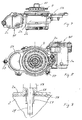
- the pressure storage device is arranged in preferred embodiments in a mounting housing which can be mounted on a machine housing of the internal combustion engine, for example a main housing or a cylinder head housing of the machine housing. In this way, the pressure storage device can be mounted by mounting the attachment housing as a unit to the internal combustion engine. If the phaser and the pressure storage device are separated by means of a remindsperr adopted from the rest of the pressurized fluid system, namely with respect to a Backflow through the Zulitezweig, the remindsperr liked can be advantageously arranged in the mounting housing.
- the ventsperr susceptible is preferably assigned only to the phaser or optionally multiple phaser for several camshafts, so specifically secures only the phaser or possibly multiple phaser against backflow of pressurized fluid through the fluid supply from, the pressure immediately upstream of the remindsperr acquired should be less than the downstream pressure.
- the pressure storage device is preferably arranged together with the phaser and this immediately downstream of the remindsperr acquired, ie in the fluid flow between the remindsperr issued and the phaser.
- the seal is held on a plurality of such centering elements of the attachment housing on this.
- the holder on the mounting housing may be frictionally engaged, but is preferably form-fitting or at least includes a positive connection in that the seal is in a rear grip with the at least one centering or preferably in the rear grip with one of a plurality of centering.
- the centering element (s) may protrude in particular on a joining surface of the attachment housing located on the mounting side.
- the holder of the seal is preferably captive, that is configured such that the seal remains in the suitable position for mounting relative to the mounting housing even if the mounting housing is held with the mounting side facing down freely.
- the at least one of the support of the seal serving centering or at least one of a plurality of the holder of the seal serving centering elements may have a passage, for example, be formed as a sleeve, the passage is sufficiently large to pass through such a hollow centering a screw for a screw the internal combustion engine or a bolt-shaped clamping element of another joint connection to lead.
- the applicant reserves the right to a housing for the phaser or the pressure storage device, in particular a mounting housing together for the pressure storage device and the remindsperr liked, optionally also the phaser, with a to hold such a seal own claim.
- the holder of the seal but also for the connection of another purpose serving housing to the internal combustion engine or other unit of advantage.
- the rotor and the stator form, as already mentioned in preferred embodiments, a hydraulic swing motor.
- the rotor and the stator can be arranged inside each other on the inside and each have at least one radially projecting wing.
- the rotor may be a ring gear and with at least one inwardly projecting wing and the stator an internal gear with at least one radially outwardly projecting wing.
- the stator forms the ring gear and has at least one, preferably a plurality of inwardly projecting blades
- the rotor forms the internal gear with at least one, preferably a plurality of outwardly projecting blades (n).
- the one or more rotor blades and the stator wing (s) limit the setting chambers in the circumferential direction. If the early-settling chamber is acted on by pressurized fluid, this produces a force acting in the circumferential direction and thus a torque which, viewed in relation to the stator, acts on the rotor in the direction of advance position or lead over. Conversely, the conditions are when the late setting chamber is acted upon by the pressure fluid and the early-acting chamber is relieved.
- the lubricating oil from the camshaft to the phaser and the optional pressure storage device or via the pressure storage device to the camshaft and from this to the phaser can be performed.
- the lubricating oil does not have to be guided via the camshaft to the phaser, but can also be supplied to it in other ways.
- the pressurized fluid is fed to the phaser via the pressure storage device, i. the pressurized fluid flows into the storage chamber and is only supplied via this to the phaser or the control chambers.
- the pressure storage device is arranged in the first embodiments in the main stream.
- the adjusting chambers and the pressure storage device are arranged in parallel with respect to the fluid flow, wherein a branch leads to the pressure storage device on the flow path of the pressurized fluid to the one or more adjusting chambers.
- the pressure storage device is arranged in the second embodiments in the secondary flow, based on the leading to the phaser main flow.
- the main flow to the device according to the invention is preferably arranged parallel to the supply current, for example to cylinders of the internal combustion engine or bearings of the camshaft and the like, so that the device flows to the pressure loss fluid with little loss.
- Embodiments have been found to be particularly advantageous in which the phaser has a control valve for controlling the pressure in the control chambers, in relation to the stator-rotor assembly centrally, preferably at one end of the camshaft, and preferably also centrally with respect to its axis of rotation, for example wholly or partially in a hollow camshaft end.
- the pressurized fluid is preferably guided via the camshaft to the control valve and supplied therefrom in accordance with the desired relative rotational angle position of the early or late setting chambers (s).
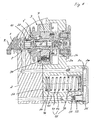
- FIG. 1 shows a camshaft phaser in a longitudinal section.
- the camshaft phaser is arranged at an end face of a camshaft 1 and serves to adjust the phase position, ie the rotational angular position of the camshaft 1 relative to a crankshaft of an internal combustion engine, for example a drive motor of a motor vehicle.
- the camshaft 1 is rotatably mounted about an axis of rotation R in a machine housing 2 of the internal combustion engine, for example in a cylinder head housing.
- the camshaft phaser comprises a stator 3, which can be rotated by the crankshaft, and a rotor 7, which can be connected in a rotationally fixed manner to the camshaft 1.
- the stator 3 is composed of a drive wheel 4, for example a sprocket, a cover 6 and an impeller 5 arranged axially between the drive wheel 4 and the cover 6.
- the drive wheel 4, the impeller 5 and the lid 6 are rotatably connected to each other.
- the assembly of the stator 3 is only an example.
- the stator 3 can also be composed of more than or instead of the three parts 4, 5 and 6 also of only two parts, for example of an integral part 4, 5 and the part 6 or the part 4 and a one-piece part 5, 6.
- the drive wheel 4 can be formed circumferentially on the outside of the impeller 5 and the cover area of the drive wheel 4, which laterally seals the stator-rotor arrangement, forms part of the rotor 7.
- the cover 6 may be part of the rotor 7.
- the stator 3 and the rotor 7 form a hydraulic swing motor.
- FIG. 3 shows the stator-rotor assembly 3, 7 in a cross section.
- the impeller 5 forms an outer component and the rotor 7 an inner component of the pivot motor.
- the hollow impeller 5 has at its inner periphery radially inwardly projecting wings 5a.
- the rotor 7 has radially outwardly projecting wings 7a, which form with the blades 5a of the stator 3 first control chambers 8 and second control chambers 9.
- the adjusting chambers 8 are arranged in the circumferential direction in each case to one side and the adjusting chambers 9 in each case to the other side of the wings 7 a of the rotor 7.
- the rotor 7 rotates relative to the stator 3 in FIG FIG. 3 clockwise to maximum in the FIG. 3 assumed end position. If the adjusting chambers 9 are pressurized and the adjusting chambers 8 relieved in pressure, the rotor 7 rotates counterclockwise. The rotational movement relative to the stator 3 in one direction of rotation corresponds to an overfeed and the relative rotational movement in the other direction to a lag of the camshaft 1 relative to the crankshaft.
- the adjusting chambers 8 are early adjusting chambers and the adjusting chambers 9 are late setting chambers.
- FIG. 3 takes the rotor 7 relative to the stator 3, the early position in which the camshaft leads relative to 1 of the crankshaft. If, instead, the late setting chambers 9 are acted on by the pressure fluid and the early adjusting chambers 8 are relieved, the rotor 7 rotates in the direction of lag until at most a retarded position.
- the early position and the late position are each specified by a stop contact. In each of the two end or extreme positions, at least one of the rotor blades 7a is in a stop contact with one of the stator blades 5a.
- the rotor 7 can not only be rotated back and forth relative to the stator 3 between these two rotational angle end positions, but can also be hydraulically fixed in any intermediate position by appropriate pressurization of both the early adjustment chambers 8 and the late adjustment chambers 9.
- the camshaft phaser has a control valve centrally arranged with respect to the stator-rotor arrangement 3, 7, with a valve housing 10 and a valve piston 20 which is arranged axially to and fro in an adjustable way in the valve housing 10 (FIG. Fig. 1 ).
- the valve piston 20 is hollow with an axially extending cavity 21, a piston inlet 22 at one axial end and a piston outlet 23, which leads radially through a jacket of the valve piston 20 surrounding the cavity 21.
- the valve piston 20 has at its side facing away from the piston inlet 22 the other axial end of a coupling member 25 for a coupling with an actuator 15, which causes the axial displacement of the valve piston 20.
- the coupling member 25 acts as an actuating tappet of the valve piston 20.
- the coupling member 25 may be integrally formed with the piston skirt surrounding the cavity 21 in one piece or optionally be axially fixed with this. It protrudes at the front end of the valve piston 20, which faces the actuator 15 axially.
- the coupling member 25 extends through an end closure wall 11 of the valve housing 10. The end closure wall 11 surrounds the coupling member 25 in close fitting and thus ensures in spite of the reciprocating coupling member 25 for the fluid-tight closure of the valve housing 10th
- the actuator 15 is an electromagnetic actuator, in the embodiment, a Axialhub electromagnet, with a current-carrying coil 16 and an armature 17, which surrounds the coil 16.
- the coil 16 is rotatably connected to the engine housing 2 of the internal combustion engine.
- the coil 16 is rotatably connected to a cover 2b, which in turn is fixedly connected to a mounted on the machine housing 2 mounting housing part 2a.
- the armature 17 is axially movable relative to the coil 16. It is with the coupling member 25 directly in a coupling engagement, which is formed as an axial pressure contact.
- the armature 17 When energizing the coil 16 acts on the armature 17 an axially directed towards the coupling member 25 actuating force acting on the coupling member 25 and thus on the valve piston 20 in the coupling engagement, a pure axial pressure contact. At the point of separation between the valve piston 20 rotating with the camshaft 1 during operation and the non-rotating actuator 15, preferably only point contact prevails.
- the armature 17 preferably has a spherical surface at its end contacting the coupling member 25.
- the coupling member 25 may have a spherical surface at its front end.
- the contact end of the armature 17 is formed as a ball sliding bearing by a ball in a pan of the armature 17 is freely rotatably mounted there.
- the control valve comprises a spring member 14 whose spring force counteracts the actuating force of the actuator 15.
- the spring member 14 is supported directly on the valve housing 10 and in the direction of the actuator 15 on the valve piston 20.
- the actuator 15 is driven by a control of the internal combustion engine, namely energized.
- the control is preferably carried out via a stored in a memory of the engine control map, for example, depending on the speed of the crankshaft, the load or other or other relevant for the operation of the internal combustion engine parameters.
- the valve piston 20 is arranged in a central axial cavity of the valve housing 10 in the manner explained back and forth movable. It has at its end facing away from the end closure wall 11 of the axial end of an axial, central leading into the housing cavity housing inlet P a, which can be fed via the camshaft 1, namely, a pressure inlet P of the camshaft 1, fluid under pressure.
- the fluid may in particular be a lubricating oil serving for lubricating the internal combustion engine, which also serves for lubricating, for example, the track bearing of the camshaft 1.
- the pressurized fluid is supplied to the control valve by way of example as preferred by the thrust bearing of the camshaft 1, that is, the pressure port P is connected to the lubricating oil supply for the thrust bearing.
- This pressurized fluid flows into the camshaft 1 at P, through the axial housing inlet P a into the valve housing 10 and through the piston inlet 22 in axial alignment with the housing inlet P a into the cavity 21.
- a piston outlet 23 through which the pressurized fluid is supplied depending on the axial position of the valve piston 20 either the Vietnamesestellhuntn 8 or the bossstellhuntn 9 to the phase position of the rotor 7 relative to the stator. 3 and thus to adjust the phase angle of the camshaft 1 relative to the crankshaft.
- the piston outlet 23 is formed by radial passages distributed over the circumference of the valve piston 20 through the jacket of the valve piston 20.
- the piston outlet 23 is arranged in an axially central portion of the valve piston 20.
- the valve housing 10 has through its jacket leading connections for the supply and discharge of the fluid to and from the adjusting chambers 8 and 9. These are a working connection A and a working connection B, a reservoir connection T a assigned to the working connection A and a reservoir connection T B assigned to the working connection B.
- the connections A to T B are in each case straight passages through the jacket of the valve housing 10.
- the connections A, B and T A extend radially over the shortest path through the jacket.
- the reservoir port T B extends obliquely outward into the phaser housing 2 a.
- the working port B of the valve housing 10 is arranged distributed over the circumference of the valve housing 10, radially extending and therefore short passages formed by the jacket of the valve housing 10.
- the terminals A, T A and T B are also each formed by a plurality of distributed around the central axis R arranged passageways.
- FIG. 1 shows the valve piston 20 in a first axial piston position in which it holds the spring member 14.
- the piston outlet 23 is connected to the working port B.
- the pressure fluid supplied via the pressure port P of the camshaft 1 flows in the axial direction through the axial housing inlet P a and the piston inlet 22 into the cavity 21 of the valve piston 20 and from there through the branching piston outlet 23 to that shown in FIG FIG. 1
- the adjusting chambers 8 associated with the working connection A are connected via the working connection A and a recess 26 formed on the outer circumference of the valve piston 20 to the reservoir connection T A and via this and a return 4 'rotating with the camshaft 1 connected to the reservoir and thus relieved in pressure.
- the recess 26 extends 360 ° circumferentially about the outer circumference of the valve piston 20. From the recess 26 from the rear seen in the axial direction behind the piston outlet 23, a further axially extending recess 27 is formed on the outer periphery of the valve piston 20, which also extends beyond the outer Extending circumference of the valve piston 20 circumferentially.
- the recess 27 is connected to the reservoir port T B in the first piston position.
- the reservoir port T B is assigned to the working port B. However, in the first piston position it is fluidically separated from the working port B by means of a sealing web of the valve piston 20 formed between the piston outlet 23 and the recess 27.
- the actuator 15 pushes the valve piston 20 from the illustrated first piston position axially in the direction of the housing inlet P A and with correspondingly large actuating force to an axial second piston position, in which no longer the working port B, but the other working port A is connected to the piston outlet 23.
- a sealing web of the valve piston 20 formed between the piston outlet 23 and the recess 26 separates the working port A from the associated reservoir port T A , so that in the second piston position the actuating chambers 9 are acted upon by the pressure fluid.
- the recess 27 connects the working port B with the reservoir port T B , so that the fluid can flow out of the adjusting chambers 8 and these are relieved of pressure.
- the rotor 7 moves accordingly in the illustration of FIG. 3 counterclockwise relative to the impeller 5 and thus to the stator 3.
- the rotatably connected to the rotor 7 camshaft 1 is adjusted in its phase position relative to the crankshaft by the same rotational angle.
- the high-pressure side fluid flowing into the control valve through the housing inlet P a urges the valve piston 20 with a first axial force acting in the direction of the actuator 15.
- a first axial force of the valve piston 20 in the direction of the actuator 15 can be flowed through, so that at its the actuator 15 facing rear between this back and the end closure wall 11, a fluid pressure builds up on the back of the valve piston 20, a counterforce, a second Exerts axial force. Since the projected by the pressurized fluid projection surface is reduced by the cross-sectional area with which the coupling member 25 protrudes through the end closure wall 11, the axial counterforce, the second axial force corresponding to the cross-sectional area of the coupling member 25 would be less than the first axial force.
- the valve piston 20 has a radially expanded piston portion 28, in the following widening 28, and the valve housing 10 has a suitably widened housing portion 18, which surrounds the widening 28 in a tight fit.
- the valve piston 20 at its outer periphery with the exception of the expansion 28, for example everywhere the same cylindrical cross-section.
- the valve piston 20 seen from the housing inlet 22 has an axial position behind the piston outlet 23 Feeder 24, which is formed by a plurality of distributed around the central axis R through channels, which are formed in a valve piston bottom.
- the widening 28 and corresponding to the housing section 18 are dimensioned such that the enlargement of the projection surface F 28 facing the actuator 15 due to the widening 28 compensates at least a predominant part of the cross-sectional area F 25 of the coupling element 25 "lost" for the compensation ( FIG. 2 ).
- the compensation surface is an outer ring surface of the projection surface F 28 .
- the projection surfaces which each generate an axial force when the valve piston 20 flows through are of the same size in both axial directions.
- the expansion 28 is preferably formed on the actuator 15 facing the front end of the valve piston 20.
- the widened housing portion 18 has a sufficient axial extent to allow the adjustment movements of the valve piston 20.
- the widening 28 forms the end of the recess 27 facing the actuator 15.
- the widened housing section 18 tapers at 13 onto the narrower cross section, which is constant in the further axial course.
- the taper 13 is formed within the recess 27, axially by way of example in the region of the reservoir port T B.
- the phase adjuster comprises a locking device 30, which mechanically fixes the rotor 7 in a specific rotational angle position relative to the stator 3 in a locking engagement. As an example, it fixes the rotor 7 as preferred in the early position.
- the locking device 30 can be brought out of the locking engagement in a release state. If the locking device 30 is in the release state, the rotor 7 can rotate relative to the stator 3 when pressure is applied to either the control chambers 8 or the control chambers 9 and corresponding pressure relief of the respective other control chambers 9 or 8, ie changes the rotational angular position of the rotor 7 relative to the stator 3 become.
- Entriegelungsemindest horrin P E is required for unlocking against a spring force Entriegelungsemindest horrin P E is required.
- the unlocking minimum pressure P E is in preferred embodiments at most as large as the hot idle pressure P HL in the pressure fluid supply to the phaser.
- the hot idling pressure P HL can be measured, in particular, at a back-up device which is arranged in the pressure fluid supply in the vicinity of the phaser in order to prevent backflow of the pressure fluid from the phaser then, when the pressure in the pressure chambers acted upon with the pressurizing fluid 8 or 9 is higher than the supply pressure immediately upstream of the remindsperr issued.
- the remindsperr Marie can be formed in particular by a check valve.
- the locking device 30 comprises a relative to the stator 3 and rotor 7 axially reciprocable locking pin 31 and a locking spring 32 which biases with its spring force the locking pin 31 in an axial direction in the locking engagement.
- the locking pin 31 is supported on the rotor 7 via the locking spring 32 and guided axially reciprocally in a guide 36 in one of the rotor blades 7a. In the locking engagement, it protrudes axially beyond an end face of the respective rotor blade 7a into an axially opposite receptacle 33 of the stator 3.
- the receptacle 33 is formed as a recess on a rotor 7 facing end side of the stator 3, for example in the lid portion of the drive wheel 4.
- Die Verriegelungs resonance 30 is connected to either one of the adjusting chambers 8 or the adjusting chambers 9, preferably only one of the ceremoniesstellhuntn 8, so that when pressure is applied to the corresponding adjusting chambers of the locking pin 31 against the spring force of the locking spring 32 moves out of the locking engagement and the mechanical fixation of the rotor 7 solved becomes.
- the space in the rotor 7, in which the locking spring 32 is arranged, is connected via a discharge line 39 to the low-pressure side of the pressurized fluid system, so that the locking pin 31 of the receptacle 33 axially opposite can not build up unlocking preventing back pressure.
- FIG. 2 shows the phaser in the unlocked state.
- the unlocking minimum pressure P E is reached or exceeded, so that the rotor 7 can be hydraulically adjusted by means of the control valve.
- the rotor 7 is already no longer in the early position.
- the locking pin 31 forms a stepped piston with a guide portion 31 a, which is always guided in the rotor blade 7 a, and a contrast slimmer engagement portion 31 b, which in the in FIG. 5 shown locking engagement engages the receptacle 33 of the stator 3.
- Locking pin 31 has a pressure surface 31d in locking engagement with receiver 33d and a further annular pressure surface 31c remote therefrom.
- the pressure surfaces 31c and 31d act in the same direction.
- the pressure surface 31c closes an annular pressure space 37, which is formed inside the rotor 7a, at an end face.
- the receptacle 33 is connected to the pressure space 37 via a connecting channel 38, which is connected with respect to the locking device 30, so to speak, is short-circuited.
- the connecting channel 38 extends in the rotor blade 7a to the front side of the rotor 7 through a narrower guide portion of the guide 36, which engages closely the engaging portion 31b of the locking pin 31, so that the locking pin 31 not only in its wider portion 31a, but also in the engaging portion 31b is guided.
- the circumferentially bounded by the guide 36 space is closed at its opposite in the locking engagement of the receptacle 33 end by means of an inserted support member 35.
- the locking spring 32 is supported with a spring end on the support element 35 and with its other spring end on the locking pin 31.
- a vent passage 39a is formed, which connects the space between the support member 35 and locking pin 31 with the secondary lead 39, which is connected to the low pressure side of the pressure fluid system, so that can not build up the unlocking significantly obstructing backpressure.
- the locking device 30 is connected for unlocking with the nearest early setting chamber 8 through a connecting channel 34.
- the connecting channel 34 leads from the pressure chamber 37 through the rotor blade 7a directly into the early adjustment chamber 8 and closes it with the locking device 30 advantageously short.
- the pressure chamber 37 is therefore connected to the early setting chamber 8 in a particularly low-resistance manner, so that its pressure is virtually free from loss and distortion in the pressure chamber 37 and also via the inner connecting channel 38 in the receptacle 33 when the pressure changes.
- the inner connecting channel 38 is, as in the FIGS. 3 and 4 can be seen, advantageously groove-shaped in the guide 36 in a radial with respect to the axis of rotation R range, for example, outside arranged.
- the required for receiving the lateral force circumferential surface of the guide 36 is reduced as little as possible.
- the arrangement of the locking device 30 near the radial end of the rotor blade 7a as this contributes to the reduction of the transverse force to be absorbed. At the same drag torque would cause a more central arrangement, closer to the axis of rotation of the rotor 7, the reduction of the lever corresponding to a larger lateral force.
- An advantage is an eccentric arrangement with respect to the circumferential direction of the locking device 30 in the rotor blade 7a.
- the locking device 30 is arranged in this eccentric arrangement in the circumferential direction closer to the side surface of the rotor blade 7a delimiting the early adjustment chamber 8 than in the side area which is opposite in the circumferential direction and delimits the late setting chamber 9. If the late setting chamber 9 is acted upon to adjust the rotor 7 in the direction of the late position, there is a comparatively long sealing web between the late setting chamber 9 and the locking device 30, in particular on the side of the stator 3 on which the receptacle 33 is arranged.
- the rotor blade 7a receiving the lock pin 31 is wider in the circumferential direction than the other rotor blades 7a.
- FIG. 3 also shows the short and direct fluid connections 7b, which lead from the central control valve 10, 20 through the rotor 7 to the control chambers 8 and 9, respectively.
- the FIG. 3 These are the fluid connections 7b to the working ports A for the late adjustment chambers 9.
- the fluid connections leading from the control valve to the ceremoniestellhuntn 8 are axially and circumferentially offset from the fluid connections 7b and extends.
- the Fluid connections 7b and also the fluid connections for the early adjustment chambers 8 are straight, at least substantially radially extending holes which open at their radially inner ends to the valve housing 20 and at their outer ends in the root regions of the rotor blades 7a in the respective control chamber 8 and 9 respectively.
- FIG. 6 shows the phaser with an associated pressure storage device 40.
- the pressure storage device 40 has a storage chamber 41 and a movable wall structure 42, which limits the storage chamber 41 on one side. Furthermore, it has a spring device 43 against whose restoring spring force the wall structure 42 for filling the storage chamber 41 is movable.
- the wall structure 42 is formed as a piston.
- the spring device 43 consists of a single mechanical spring, by way of example as preferred of a claimed when loading the storage chamber 41 to pressure coil spring.
- the wall structure 42 is freely movable back and forth, so that their chamber pressure is always distortion-free available in the at least partially filled state.
- the pressure storage device 40 is arranged in the flow path of the pressurized fluid to the phaser upstream of the control valve 10, 20.
- the phaser is connected via a feed channel 50 to the pressurized fluid system.
- a feed channel 50 In the feed channel 50 is aradsperr adopted 51, for example a check valve, upstream of the phaser and the pressure storage device 40 is arranged, which prevents a backflow of pressurized fluid.
- a filter element 52 is also disposed between the remindsperr issued 51 and the storage chamber 41.
- the restraining device 51 opens in the direction of the pressure storage device 40, so that this corresponding to the pressure and can partially or completely fill the restoring spring force of the spring device 43.
- the maximum filling volume is reached when the wall structure 42 abuts against a stop of the pressure storage device 40.
- the storage chamber 41 is connected via a short path via a downstream downstream feed channel 53 with the phaser. In the exemplary embodiment, the connection is made via the camshaft 1.
- Via a discharge channel 46 ensures that the storage chamber 41 can fill without significant backpressure.
- the discharge channel 46 connects the space at the rear of the movable wall structure 42 with the low pressure side of the pressurized fluid supply system.
- the storage chamber 41 is covered at an open side by a lid 2c.
- the lid 2c forms as preferred, but only by way of example, a stop for the piston 42 and the other as preferred, but also only by way of example, an inlet 2d leading directly into the storage chamber 41 and an outlet 2e leading directly from the storage chamber 41.
- the Storage chamber 41 is connected to the feed channel 50 via inlet 2d and to downstream feed line 53 leading to phaser via outlet 2e.
- the feed channel 53 extends as preferred, but only as an example along the storage chamber 41, in the example parallel to the direction of movement of the piston 42, and to the lid 2c, where it opens into the outlet 2c.
- the pressure storage device 40 is arranged in a leading to the phaser main flow of the pressurized fluid by the example by way of the machine housing 2 and the connected feed channel 50 supplied pressurized fluid only via the pressure storage device 40 while flowing through the storage chamber 41 in the advancing to the phaser feed channel 53 and this example again passes through the machine housing 2 to the pressure port P.
- Control valve leading supply channel 53 connects, be formed on the cover 2c facing the end face of the attachment housing 2a, for example, as one or a respective groove-shaped recess on the lid 2c facing the end of the storage chamber 41 surrounding wall. It is merely necessary to ensure that a certain space remains between the piston 42 and the cover 2c, which space is connected to the supply channel 50 or the supply channel 53 via the inlet or outlet formed in such an alternative manner.
- This solution offers cost advantages in the production, since the lid 2c in such embodiments on its the storage chamber 41 facing end face can be easily plan formed.
- the acted upon by the pressurized fluid in the storage chamber 41 surface of the wall structure 42 and the spring stiffness and optionally an existing without pressurization spring preload of the spring means 43 are tuned to the system pressure in the pressurized fluid supply system that the storage chamber 41 begins to fill at the latest when in the pressurized fluid supply system, the hot idle pressure P HL is reached.
- the Grebeginntik P FB is the pressure at which the filling begins, ie in which the wall structure 42 is moved against the restoring spring force of the spring means 43 and an increase in the filling volume against a minimum volume of the storage chamber 41 begins.
- the minimum volume may be zero, but in practice the storage chamber 41 will have some residual volume in the initial state.
- the Grebeginntik P FB is at most as large as the hot idling pressure P HL , preferably it is smaller.
- the pressure storage device 40 thus becomes effective even at low system pressures.
- the pressure storage device 40 is further designed so that the filling of the storage chamber 41 is not completed when the pressure in the storage chamber 41 corresponds to the hot idle pressure P HL , ie at idle speed, but only at a higher inflation pressure.
- the Pressure accumulator 40 thus operates out of the hot idle, preferably even at a lower speed than the idle speed, up to a lying above the idle speed always with adjusted compensation or accumulator pressure.
- the pressure storage device 40 is tuned so that the storage chamber 41 reaches its maximum fill volume at the earliest at double idle speed, more preferably at least three times idle speed.
- the maximum filling volume can be absolutely limited as in the embodiment by a stop contact, in principle, however, a stop limit is not required.
- the pressure storage device 40 can also fill or empty corresponding to the respective system pressure over the entire speed range of the internal combustion engine.
- filling over the entire speed range is not required and not always desirable because the spring device 43 is subject to limitations in terms of its spring rigidity. Such limitations can be counteracted by a series or parallel connection of several spring members, for example, a spring member low spring stiffness and a stiffer spring member, wherein in the lower speed range primarily the softer spring member and at higher speed the stiffer spring member only to a relevant extent or at all first would tension.
- the locking device 30 is tuned by appropriate design of the pressure surfaces 31c and 31d of the locking pin 31 and the spring stiffness or a spring bias of the locking spring 32 to the system pressure so that the Entriegelungsemindesttik P E also at most as large as the hot idling pressure P HL , preferably smaller than this , More preferably, the unlocking minimum pressure P E is at most as large as the filling start pressure P FB , preferably smaller than this.
- the comparatively low unlocking minimum pressure P E ensures early unlocking, at low speeds of the internal combustion engine, and thus already an adjustability of the rotor at a correspondingly low speed.
- Such a sensitive unlocking counteracts when the locking device 30 with the in the ceremoniestellkanimer 8 ( FIG. 3 ) prevailing pressure is unlocked, the application of both pressure surfaces 31c and 31d at the same time further favoring acts, as a result, the spring force of the locking spring 32 can be selected correspondingly high, resulting in a secure locking engagement result.
- the hot idling pressure P HL can be measured, in particular close to the restraint device 51, in particular upstream of it.
- the filling start pressure P FB and the minimum filling pressure for a complete filling can be measured in the same place, assuming of course that the pressure in the storage chamber 41 at the time of measurement is not just greater than the pressure in front of the remindsperr owned 51.
- the minimum unlocking pressure P E can also be measured there. The locking engagement should be released when the unlocking minimum pressure P E is reached at said point.
- FIG. 7 shows the attachment housing with the attachment housing part 2a and the covers 2b and 2c, which receives the phaser, substantially the stator 3, the rotor 7 and the central control valve from which the valve housing 10 protrudes on the mounting side of the attachment housing 2a, 2b, 2c.
- the attachment housing for example the attachment housing part 2a, also includes the same pressure accumulator device 40, so summarizes the phaser and the pressure storage device 40 together to form a mounting unit.
- This mounting unit is mounted on the engine housing of the internal combustion engine, for example on a cylinder head housing, with the cover removed 2b, which is mounted after mounting on the housing part 2a.
- the remindsperr worn 51 is advantageously also in the mounting housing 2a, 2b, 2c arranged.
- FIG. 8 shows the attachment housing 2a, 2b, 2c in an end view of the mounting side.
- a seal 56 is arranged, which ensures in the assembled state for the seal between the machine housing and the mounting housing 2a, 2b.
- centering elements 57 protrude beyond the seal 56, relative to the mounted state, in the direction of the machine housing and, in the assembled state, into adapted centering counter-structures of the machine housing.
- the centering elements 57 are illustrative pin-shaped and can be hollow in cross section and formed in such embodiments as centering.
- the centering elements 57 serve not only to center and thereby facilitate assembly, but also keep the seal 56 on the mounting side of the attachment housing 2a, 2b in an immediately suitable for mounting location by the seal 56 with at least one of the centering 57, preferably with several or all centering elements 57, in a holding engagement, for example in a rear grip. In holding engagement, the seal is captively connected to the mounting housing.
- FIG. 9 shows such a rear handle representative of preferably one or more others.
- the illustrated centering element 57 extends through an opening of the seal 56.
- the centering element 57 is in the attachment housing 2a, 2b inserted, is held firmly in a corresponding receptacle and protrudes as I said about the end face of the attachment housing 2a, 2b a bit far ahead. Close to the end face it is fitted in the protruding section, so that the seal 56 engages with its centering element 57 surrounding the opening edge 58 in the sidecut and so the seal 56 holding the rear handle is formed.
- the waist can be replaced by another retaining engagement element such as a projection such as a flange.
- the functions of centering the attachment housing 2a, 2b and the holder of the seal 56 and the creation of the actual joint connection of mounting housing 2a, 2b and machine housing are concentrated in a confined space by a clamping element 59 of the joint connection, by the hollow centering 57, an example Screw, is guided.
- the clamping element 59 extends through the centering element 57 and is connected in its projecting portion with the machine housing, for example in a screw engagement 2f.
- FIG. 10 shows the locking device 30 again in longitudinal section.
- the locking pin 31 is in locking engagement and is retracted with maximum engagement length L 31 in the receptacle 33. Due to the cylindrical or optionally also with a very acute angle of, for example, 2 ° or 3 ° conical circumference of the locking pin 31 acts blocking over its entire maximum engagement length L 31 in memorisswirk Scheme together with the receptacle 33.
- FIG. 11 shows an improved locking device 30 of a first modified embodiment in longitudinal section.
- This locking device 30 differs from the locking device 30 of FIGS. 1 to 10 only with respect to the locking pin, which is therefore provided with the reference numeral 60.
- the recording is also provided with a different reference numeral, the reference numeral 80, but corresponds to the receptacle 33 of FIGS. 1 to 10 .
- the locking pin 60 is retracted in the locking direction L, which coincides with a central longitudinal axis of the locking pin 60, in the receptacle 80 with maximum engagement length L 60 and lies in the locking direction L to stop.
- the stop is exemplified by a projecting at the bottom of the receptacle 80 flat elevation.
- the locking pin 60 tapers concisely in its engagement region extending over the maximum engagement length L 60 .
- the lock pin 60 has a front pin portion 61 and a rear pin portion 62 in its engagement portion.
- the front pin portion extends in the locking direction L to the front free end of the locking pin 60.
- the rear pin portion 62 is also dipped into the receptacle 80 in locking engagement and overlaps with the opening edge 83 of the receptacle 80. It extends in locking engagement a distance in the direction to the free end of the locking pin 60.
- the engagement portion of the locking pin 60 is comprised of the two pin portions 61 and 62, which together extend beyond the maximum engagement length L 60 .
- Front pin section 61 has a length L 61 measured in the locking direction L
- the rear pin section 62 has a length L 62 whose sum corresponds to the maximum L 60
- the receptacle 80 also has an overlapping in locking engagement with the front Pinabrisk 61 lower receiving portion 81 of the length L 61 and a to the edge 83 of the receiving opening extending upper accommodating portion 82 having a length L 62 corresponding length. In the locking engagement thus overlap the front pin portion 61 with the lower receiving portion 81 and the rear pin portion 62 with the upper receiving portion 82nd
- the front pin portion 61 has over its entire length L 61 on the outer circumference on an inclination ⁇ to the locking direction L, which is so large that the locking pin 60, should he press in the region of the front pin portion 61 against the opening edge 83, not clamp and a Self-locking of pin 60 and receptacle 80 can not take place, but the locking pin 60 is pressed in the force exerted by the rotor 7 transverse force against the spring force in the direction of the release position. By dipping only with the front pin portion 61, therefore, the rotor 7 can not be blocked relative to the stator 3.
- the relative rotational movement blocking blocking contact can reach only the rear pin portion 62, which may be tapered cylindrical or slightly conical with a very small cone angle of, for example, 3 ° or 4 ° to the free end of the locking pin 60 for this purpose.
- a blocking contact of the front pin portion 61 is prevented by the large inclination ⁇ , which is preferably at least 45 °.
- the inclination ⁇ is preferably at most 80 °. Slopes are particularly favorable by 60 °, namely from the range of 60 ° ⁇ 10 °.
- the inclination values apply in each case to the entire length L 61 of the front pin section 61.
- the inclination ⁇ may be variable, but the inclination ⁇ is preferably constant over the length L 61 and the pin section 61 is correspondingly conical on the outer circumference.
- the front pin portion 61 is a truncated cone by the front end of the locking pin 60 is formed as a planar end face.
- the rotor 7 is now to be adjusted in the direction of the retarded position, two movements can take place simultaneously when reversing: because of the pressure reduction in the early adjustment chambers 8 and the pressure build-up in the late adjustment chambers 9, the rotor 7 begins to rotate relative to the stator 3 in the direction of the retarded position , If the early-acting chambers 8 are relieved of pressure, the locking pin 60 starts driven out by the spring force, and there is the possibility that it dips into the receptacle 80. Depending on which of the two Movements is the faster, therefore finds a locking or adjustment of the rotor 7 instead. Although the locking pin 60 may initially dip easily into the receptacle 80 because of the significantly large length L 61 and the large inclination ⁇ .
- the locking pin 60 can be urged back in the direction of the release position in cooperation of front pin portion 61 and opening edge 83 by the transverse force exerted by the rotor 7 against the locking direction 2. Since the system of locking pin 60 and locking spring 32 is subject to a certain inertia, the time required for the extension by the length L 61 L is sufficient to prevent jamming of locking pin 60 and receptacle 80 safer than conventional locking pins.
- the pressure at which the rotor 7 can still be reliably adjusted relative to the stator 3 is reduced. It ensures a more reliable reversal in the pressure chamber connected to the control chamber at low pressure.
- the same advantage arises when starting the internal combustion engine. As a result of the fluid pressure that builds up in the process, the locking pin 60 only has to be pushed back by the length L 62 of the rear pin section 62 against the spring force. The risk of tilting due to shear forces is reduced.
- the tilt jump takes place advantageously within a very small length of preferably less than 10% and more preferably still less than 5% of the maximum engagement length L 60 or over a correspondingly small radius.
- the production can also be set up so that the inclination jump takes place as abruptly as possible in terms of manufacturing technology.
- the relatively sharp geometric separation into the two functionally different pin sections 61 and 62 as explained above enables unlocking when reversing the rotor 7 even at low pressures, but at the same time becomes too by the interaction of the rear pin portion 62 with the upper receiving portion 83 a secure blocking at not yet the pressure fluid filled phaser, in particular in start phases of the internal combustion engine, guaranteed. Because of the reduction of the minimum unlocking pressure required for unlocking, the unlocking can be ensured even in hot idle phases of the internal combustion engine safer than in the known locking devices. The availability of the phaser for camshaft adjusting operations is increased.
- the locking pin 60 corresponds to the locking pin 31, so that reference can be made to the relevant embodiments.
- reference numeral 63 is entered for the first printing surface.
- the second pressure surface 64 is formed by the inclined peripheral surface of the front pin portion 61, for the pressurization for unlocking apply the statements in connection with the locking pin 31, however, in the same way.
- the lengths L 61 and L 62 are preferably each at least 0.5 mm, more preferably at least 1 mm.
- the ratio of the length L 61 of the non-blocking acting pin portion 61 to the length L 62 of the blocking acting pin portion 62 is selected in appropriate embodiments in the range of 1 ⁇ 0.5.
- FIG. 12 shows a differently modified locking device 30, a second embodiment of the invention, in which a locking pin 70 is used, which the locking pin 31 of FIGS. 1 to 10 equivalent.
- this locking device 30 has a modified receptacle 90.
- the receptacle 90 comprises a lower receiving portion 91, which is formed as in the receptacles 33 and 80, and an upper receiving portion 92 which extends to the opening edge 93 of the receptacle 90 and widening towards this or from the opening edge 93 to the lower receiving portion 91 continuously tapers over its entire length.
- the length of the lower receiving portion 91 corresponds to the length L 71 of the front pin portion 71
- the length of the upper receiving portion 92 corresponds to the length L 72 of the rear pin portion 72, but the pin portions 71 and 72 continue each other continuously without inclination changes.
- the front pin portion 71, in particular the front free end of the locking pin 70, and the upper receiving portion 92 cooperate in the same manner as the front pin portion 61 and the upper receiving portion 82 of the first example.
- the front pin portion 71 acts in this embodiment, however with the lower receiving portion 91 in locking engagement together blocking.
- the Inclination at the outer periphery of the front pin portion 71 and the inclination at the inner periphery of the lower receiving portion 91 are correspondingly small.
- the said peripheral surfaces may in particular be cylindrical or conical with a slight inclination.
- the tapering of the locking pin or the receptacle according to the invention also has advantages over the functional advantages of the locking device with respect to the development of the phaser until it is ready for series production. If, for example, the locking pin and the receptacle are formed in the early stages of development with continuous cylindrical or slightly conical circumferential effective ranges and the locking spring 32 adapted, even in later development stages, for example in the test phase on the engine test bench or even later, a locking pin conventionally shaped up to that point be replaced by a locking pin according to the invention or a conventionally shaped receptacle by a recording according to the invention.
- the design of the locking spring 32 and the geometry of locking pin and recording moreover, nothing must be changed.
- FIG. 13 shows a locking device 30 of a third embodiment according to the invention with a modified locking pin 100 and a modified receptacle 110. From the longitudinal section of FIG. 13 is in FIG. 14 the area of the locking engagement is shown enlarged.
- the locking pin 100 has a front pin portion 101 and a rear pin portion 102 that form the engagement portion with which the locking pin 100 engages the receptacle 110 in locking engagement.
- the rear pin portion 102 tapers toward the free end of the locking pin 100.
- the pin portion 102 tapers over its entire length, the in FIG. 14 L 102 is tapered, conically everywhere with the same inclination.
- the cooperating in locking engagement with the pin portion 102 upper receiving portion 112 tapers congruent to the pin portion 102 toward the bottom of the receptacle 110, in the embodiment according to conical with anywhere the inclination of the rear pin portion 102 corresponding inclination.
- the lower receiving portion 111 has the same inclination as the upper receiving portion 112 almost to the bottom of the receptacle 110. This inclination is so small that the locking pin 100 is blocked in the locking engagement in the region of the pin portion 102.
- the front pin portion 101 has the pronounced strong inclination ⁇ , so that the locking pin 100 in the front pin portion 101 is not blocked.
- the comments on the other embodiments apply.
- the front pin portion 101 is shorter in relation to the rear pin portion 102 than in the two previous embodiments.
- the aspect ratio L 102 : L 101 that is, the length of the rear pin portion 102 to the length of the front pin portion 101, is about 5.
- the upper receiving portion 112 has, in an upper portion extending to the opening edge 113 and the opening edge 113, over a length L 113 , the in FIG. 14 is registered, an inclination which is significantly greater than the inclination in the adjoining lower portion of the upper receiving portion 112.
- the measured in the direction of movement of the locking pin 100 length L 113 is greater than it would be in a pure chamfering of the receptacle 114.
- the length L 113 with the comparatively large, ie, flat, slope is preferably at least one fifth of the total length L 100 of the engagement portion of the locking pin 100.
- the length L 101 of the front pin portion 101 and the length L 113 of the upper one Part of the upper receiving portion 112 at least substantially equal. If the locking pin 100 protrudes into the receptacle 110 only with its front pin section 101, a comparatively large clearance is thereby obtained in the transverse direction, ie in the direction of the relative rotational movement of the stator 3 and the rotor 7.
- phase adjuster corresponds to the exemplary embodiments already described above.
- the locking pin is formed in the illustrated embodiments as a stepped piston.
- the locking pin in all embodiments may instead be designed as a piston with a single-cylindrical guide, so that such a locking pin and a leading him in the locking and unlocking direction rotor 7 only have cylindrical guide circumferential surfaces.
- the external connection channel 34 which in the illustrated embodiments, the Vietnamese subcutaneous tissue service provider 8 and in alternative embodiments, the opposite handedstellhunt 9 connects directly to the locking device 30, open into a connecting channel 38 corresponding internal connection channel, which separates the pressurized fluid from the corresponding Entriegelungsstellhunt 8 or 9 in the respective receptacle and there against the pressure surface of the locking pin, for example, the locking pin 31, 60, 70 or 100, leads to effect the unlocking.
- a locking pin with only a single cylindrical guide is in terms of manufacturing and also to avoid over-determination in the guiding engagement of pin and rotor beneficial.
Landscapes
- Engineering & Computer Science (AREA)
- Mechanical Engineering (AREA)
- General Engineering & Computer Science (AREA)
- Valve Device For Special Equipments (AREA)
Claims (15)
- Régulateur de phase destiné à régler la position angulaire de rotation d'un arbre à cames par rapport à un vilebrequin d'un moteur à combustion interne, le régulateur de phase comportant :(a) un stator (3) pouvant être entraîné en rotation par le vilebrequin,(b) un rotor (7) pouvant être entraîné en rotation par le stator (3) et pouvant être couplé à celui-ci pour entraîner l'arbre à cames (1) en rotation,(c) une chambre de réglage d'avance (8) pour générer un moment de rotation agissant sur le rotor (7) dans le sens de l'avance par rapport au stator (3) et une chambre de réglage de retard (9) pour générer un moment de rotation agissant sur le rotor (7) dans le sens du retard par rapport au stator (3), lesquelles chambres de réglage pouvant être soumises à l'action d'un fluide sous pression pour générer le moment de rotation respectif afin de pouvoir régler la position angulaire de rotation du rotor (7) par rapport au stator (3),(d) une goupille de verrouillage (60 ; 70 ; 100) qui est supportée de manière mobile en va et vient par un élément parmi le stator (3) et le rotor (7) dans un sens de verrouillage et de déverrouillage (± L) pour venir en prise de verrouillage et libérer la prise de verrouillage, et qui peut être déplacée pour libérer la prise de verrouillage en appliquant le fluide sous pression à l'encontre d'une force élastique,(e) et un logement (80 ; 90 ; 110) formé par l'autre élément parmi le stator (3) et le rotor (7), dans lequel la goupille de verrouillage (60 ; 70 ; 100) vient en prise de verrouillage avec une partie de goupille avant (61 ; 71 ; 101) qui atteint une extrémité libre de la goupille de verrouillage (60 ; 70 ; 100) et avec une partie de goupille arrière (62 ; 72 ; 102) éloignée de l'extrémité libre, et empêche ainsi une rotation du rotor (7) par rapport au stator (3),(f) dans lequel la partie de goupille arrière (62 ; 72 ; 102) a une longueur (L62 ; L72 ; L102) mesurée jusqu'à un bord d'ouverture (83 ; 93 ; 113) du logement (80 ; 90 ; 110) lorsqu'elle vient en prise de verrouillage dans le logement (80 ; 90 ; 110), qui est au plus trois fois supérieure à la longueur (L61 ; L71 ; L101) de la partie de goupille avant (61 ; 71 ; 101), et le logement (80 ; 90 ; 110) ayant respectivement des longueurs correspondantes comporte une partie de logement inférieure (81 ; 91 ; 111) qui chevauche la partie de goupille avant (61 ; 71 ; 101) en prise de verrouillage et une partie de logement supérieure (82 ; 92 ; 112) comportant le bord d'ouverture (83 ; 93 ; 113), qui chevauche la partie de goupille arrière (62 ; 72 ; 102) en prise de verrouillage, dans lequel(g) soit la partie de goupille avant (61 ; 101) a une inclinaison (α) sur une circonférence extérieure par rapport au sens de verrouillage et de déverrouillage (± L), qui est si grande sur toute la longueur (L61 ; L101) de la partie de goupille avant (61 ; 101) que le rotor (7) ne peut pas être bloqué uniquement par la mise en prise de la partie de goupille avant (61 ; 101), et la mise en prise de la partie de goupille arrière (62 ; 102) entraîne le blocage,(h) soit la partie de logement supérieure (92) a une inclinaison (β) sur une circonférence intérieure par rapport au sens de verrouillage et de déverrouillage (± L), qui est si grande sur toute la longueur (L72) de la partie de logement supérieure (92) que le rotor (7) ne peut pas être bloqué uniquement par la mise en prise de la partie de goupille avant (71) dans la partie de logement supérieure (92), et la mise en prise de la partie de goupille avant (71) dans la partie de logement inférieure (91) entraîne le blocage, et dans lequel l'inclinaison (α ; β) sur toute la longueur soit de la partie de goupille avant (61 ; 101) soit de la partie de logement supérieure (92) est d'au moins 45° et d'au plus 75°.
- Régulateur de phase selon la revendication 1, caractérisé en ce que soit la partie de goupille avant (61 ; 101) s'amincit en direction de l'extrémité libre de la goupille de verrouillage (60 ; 100), soit la partie de logement supérieure (92) s'amincit en direction de la partie de logement inférieure (91), au moins dans une zone circonférentielle active, de manière conique, tronconique ou concave lorsque vu de l'extérieur.
- Régulateur de phase selon l'une des revendications précédentes, caractérisé en ce que la partie de goupille avant (61 ; 101) est adjacente à la partie de goupille arrière (62 ; 102) et la partie de logement inférieure (91) est adjacente à la partie de logement supérieure (92) et l'inclinaison (α ; β) varie brusquement dans chaque zone limite lors de la mise en oeuvre de la caractéristique (g) des parties de goupille (61, 62 ; 101, 102) et lors de la mise en oeuvre de la caractéristique (h) des parties de logement (91, 92), en variant par à-coups de plus d'au moins 45° au cours de l'inclinaison (α ; β) obtenue dans le sens de verrouillage et de déverrouillage (± L).
- Régulateur de phase selon l'une des revendications précédentes, caractérisé en ce que lors de la mise en oeuvre de la caractéristique (g), le rapport de la longueur de la partie de goupille avant sur la longueur de la partie de goupille arrière (L61 : L62) et lors de la mise en oeuvre de la caractéristique (h), le rapport de la longueur de la partie de logement supérieure sur la longueur de la partie de logement inférieure (L72 : L71) est choisi dans la plage de 0,5 à 1,5.
- Régulateur de phase selon l'une des revendications précédentes, caractérisé en ce que la longueur (L61) de la partie de goupille avant (61), la longueur (L62) de la partie de goupille arrière (62), la longueur (L71) de la partie de logement inférieure (91) et la longueur (L72) de la partie de logement supérieure (92) sont respectivement d'au moins 1 mm.
- Régulateur de phase selon l'une des revendications précédentes, caractérisé en ce que la partie de goupille arrière (62 ; 72 ; 102) est cylindrique sur au moins une partie de sa longueur (L62 ; L72 ; L102) au moins dans une zone circonférentielle active qui coopère avec le logement (80 ; 90 ; 110) en prise de verrouillage, ou a une inclinaison de moins de 20°.
- Régulateur de phase selon l'une des revendications précédentes, caractérisé en ce que(i) soit la partie de goupille avant (61 ; 101) présente l'inclinaison importante (α) selon la caractéristique (g) et la partie de logement supérieure (82 ; 112) est cylindrique sur au moins une partie de sa longueur (L62 ; L102) qui chevauche la partie de goupille arrière (62 ; 102) en prise de verrouillage, au moins dans une zone circonférentielle active qui coopère avec la partie de goupille arrière (62 ; 102) en prise de verrouillage, ou a une inclinaison de moins de 20°,(ii) soit la partie de logement supérieure (92) présente l'inclinaison importante (β) selon la caractéristique (h) et la partie de goupille avant (71) est cylindrique sur au moins une partie de sa longueur (L71) qui chevauche la partie de logement inférieure (91) en prise de verrouillage, au moins dans une zone circonférentielle active qui coopère avec la partie de logement inférieure (91) en prise de verrouillage, ou a une inclinaison de moins de 20°.
- Régulateur de phase selon l'une des revendications précédentes, caractérisé en ce que la partie de goupille avant (61 ; 101) est formée au moins dans une zone circonférentielle active selon la caractéristique (g) qui coopère avec le logement (80) lors du verrouillage, et la partie de goupille arrière (62 ; 102) est cylindrique au moins dans une zone circonférentielle active qui coopère avec la partie de logement supérieure (82 ; 112) en prise de verrouillage, puis jusqu'à la partie de goupille avant (61 ; 101), ou a une inclinaison de moins de 20°.
- Régulateur de phase selon l'une des revendications précédentes, caractérisé en ce que la partie de goupille avant (61 ; 101) est formée sur tout le pourtour de sa circonférence selon la caractéristique (g), est de préférence conique sur tout le pourtour, et la partie de goupille arrière (62 ; 102) est cylindrique sur tout le pourtour de sa circonférence, puis jusqu'à la partie de goupille avant (61 ; 101), ou est conique avec une inclinaison de moins de 20°.
- Régulateur de phase selon l'une des revendications précédentes, caractérisé en ce qu'un espace de pression (37) qui reçoit la goupille de verrouillage (60 ; 70 ; 100) ou le logement (80 ; 90 ; 110) est relié à la chambre de réglage d'avance (8) ou à la chambre de réglage de retard (9) pour libérer la prise de verrouillage.
- Régulateur de phase selon l'une des revendications précédentes, caractérisé en ce que la goupille de verrouillage (60 ; 70 ; 100) est supportée par un élément parmi le rotor (7) et le stator (3) par l'intermédiaire d'un ressort de verrouillage (32), et est guidée de manière axialement mobile en va-et-vient par le premier élément parmi le rotor (7) et le stator (3) entre la prise de verrouillage et la position de libération.
- Régulateur de phase selon l'une des revendications précédentes et présentant l'une des caractéristiques suivantes :(i) la goupille de verrouillage (60 ; 70 ; 100) comporte une première surface de pression annulaire (63, ; 103) située à l'extérieur du logement (80 ; 90 ; 110) lorsque la prise de verrouillage est présente, et une seconde surface de pression (64 ; 104) située dans le logement (80 ; 90 ; 110) lors la prise de verrouillage est présente, lesquelles surfaces de pression peuvent chacune être soumises à l'action du fluide sous pression pour libérer la prise de verrouillage et sont reliées l'une à l'autre de telle sorte que le fluide sous pression destiné à libérer la prise de verrouillage arrive jusqu'à l'une des surfaces de pression et de là, également jusqu'à l'autre des surfaces de pression ou aux deux surfaces de pression par l'intermédiaire d'une dérivation,(ii) la goupille de verrouillage est uniquement guidée jusqu'à un guide simplement cylindrique, et une surface de pression (64 ; 74 ; 104) située dans le logement (80 ; 90 ; 110) lorsque la prise de verrouillage est présente peut être soumise à l'action du fluide sous pression par l'intermédiaire d'un canal de liaison interne (38) qui est formé sur ou dans la goupille de verrouillage (60 ; 70 ; 100) ou dans l'espace de pression qui reçoit celle-ci, et par l'intermédiaire d'un canal de liaison supplémentaire (34) menant dans le canal de liaison (38) soit à partir de la chambre de réglage d'avance (8) soit à partir de la chambre de réglage de retard (9).
- Régulateur de phase selon l'une des revendications précédentes, caractérisé en ce que le rotor (7) supporte la goupille de verrouillage (60 ; 70 ; 100) de manière mobile dans un espace de pression (37) et comporte un canal de liaison (34) qui débouche dans l'une des chambres de réglage (8, 9), soit dans la chambre de réglage d'avance (8) soit dans la chambre de réglage de retard (9), et établit une liaison entre l'espace de pression (37) et cette chambre de réglage (8 ; 9) pour libérer la prise de verrouillage.
- Régulateur de phase selon l'une des revendications précédentes et présentant au moins l'une des caractéristiques suivantes :(i) la goupille de verrouillage (60 ; 70 ; 100) est agencée de manière mobile dans une ailette (7a) du rotor (7) et de manière excentrée dans une direction circonférentielle lorsque vue dans une vue de face du rotor (7),(ii) la goupille de verrouillage (60 ; 70 ; 100) est agencée de manière axialement mobile dans une ailette (7a) du rotor (7) et une extrémité radiale de l'ailette (7a) plus proche de l'axe de rotation (R) du rotor (7).
- Régulateur de phase selon l'une des revendications précédentes et présentant au moins l'une des caractéristiques suivantes :(i) la goupille de verrouillage (100) correspond à la caractéristique (g), et la partie de goupille arrière (102) s'amincit avec une inclinaison en direction de la partie de goupille avant (101) et la partie de logement supérieure (112) s'amincit avec une inclinaison en direction de la partie de logement inférieure (111), l'inclinaison de la partie de goupille arrière et l'inclinaison de la partie de logement supérieure étant si petites que la partie de goupille arrière (102) est bloquée en prise de verrouillage par la partie de logement supérieure (112),(ii) la goupille de verrouillage (100) correspond à la caractéristique (g), la partie de logement supérieure (112) s'amincit à partir du bord d'ouverture (113) du logement (110) en direction de la partie de logement inférieure (111) avec une première inclinaison et plus profondément dans le logement (110) avec une seconde inclinaison, et la première inclinaison est plus grande que la seconde inclinaison, la seconde inclinaison étant si faible qu'elle entraîne un blocage de la partie de goupille arrière (102) en prise de verrouillage et la première inclinaison étant si élevée que le rotor (7) ne peut pas être bloqué uniquement par la mise en prise de la goupille de verrouillage (100) dans la zone de la première inclinaison (α).
Applications Claiming Priority (1)
| Application Number | Priority Date | Filing Date | Title |
|---|---|---|---|
| DE201110004539 DE102011004539A1 (de) | 2011-02-22 | 2011-02-22 | Nockenwellen-Phasensteller mit verbesserter Verriegelungseinrichtung |
Publications (3)
| Publication Number | Publication Date |
|---|---|
| EP2492459A2 EP2492459A2 (fr) | 2012-08-29 |
| EP2492459A3 EP2492459A3 (fr) | 2013-01-23 |
| EP2492459B1 true EP2492459B1 (fr) | 2014-12-10 |
Family
ID=45656466
Family Applications (1)
| Application Number | Title | Priority Date | Filing Date |
|---|---|---|---|
| EP12156574.1A Not-in-force EP2492459B1 (fr) | 2011-02-22 | 2012-02-22 | Régulateur de phase d'arbres doté d'un dispositif de verrouillage amélioré |
Country Status (2)
| Country | Link |
|---|---|
| EP (1) | EP2492459B1 (fr) |
| DE (1) | DE102011004539A1 (fr) |
Cited By (1)
| Publication number | Priority date | Publication date | Assignee | Title |
|---|---|---|---|---|
| EP4332356A1 (fr) * | 2022-09-01 | 2024-03-06 | Mechadyne International Ltd. | Ensemble goupille de verrouillage mécanique |
Families Citing this family (9)
| Publication number | Priority date | Publication date | Assignee | Title |
|---|---|---|---|---|
| DE102011076652B4 (de) | 2011-05-27 | 2017-06-01 | Schwäbische Hüttenwerke Automotive GmbH | Vorrichtung zur Verstellung der relativen Drehwinkelposition geschachtelter Nockenwellen |
| DE102011084059B4 (de) | 2011-10-05 | 2016-12-08 | Schwäbische Hüttenwerke Automotive GmbH | Steuerventil mit integriertem Filter und Nockenwellen-Phasensteller mit dem Steuerventil |
| DE102012213002A1 (de) | 2012-07-24 | 2014-01-30 | Schwäbische Hüttenwerke Automotive GmbH | Nockenwellen-Phasensteller mit Dichtungshülse |
| FR3001255B1 (fr) * | 2013-01-24 | 2016-07-29 | Delphi Automotive Systems Lux | Dephaseur d'arbre a cames |
| DE102013204869A1 (de) * | 2013-03-20 | 2014-10-09 | Schaeffler Technologies Gmbh & Co. Kg | Steuerkolben für ein Zentralventil und Herstellungsverfahren für einen Steuerkolben eines Zentralventils |
| DE102013219075B4 (de) * | 2013-09-23 | 2020-11-26 | Schaeffler Technologies AG & Co. KG | Multiverriegelung eines Nockenwellenverstellers |
| DE102013219078B4 (de) * | 2013-09-23 | 2021-02-18 | Schaeffler Technologies AG & Co. KG | Multiverriegelung eines Nockenwellenverstellers |
| DE102014003933A1 (de) * | 2014-03-20 | 2015-09-24 | Gkn Sinter Metals Engineering Gmbh | Variabler Nockenwellenversteller mit Verriegelungsscheibe, Verriegelungsscheibe und Verfahren zur Herstellung derselben |
| CN114396239B (zh) * | 2022-01-29 | 2023-06-13 | 深圳大学 | 保压保瓦斯取芯器与高压管安全卸压及密封引流转接管套 |
Family Cites Families (12)
| Publication number | Priority date | Publication date | Assignee | Title |
|---|---|---|---|---|
| US5823152A (en) | 1995-06-14 | 1998-10-20 | Nippondenso Co., Ltd. | Control apparatus for varying a rotational or angular phase between two rotational shafts, preferably applicable to a valve timing control apparatus for an internal combustion engine |
| EP1128028B8 (fr) * | 1996-03-28 | 2012-11-07 | Aisin Seiki Kabushiki Kaisha | Dispositif de commande du calage des soupapes |
| JP3760566B2 (ja) * | 1997-06-05 | 2006-03-29 | アイシン精機株式会社 | 弁開閉時期制御装置 |
| JP2000230511A (ja) * | 1998-12-07 | 2000-08-22 | Mitsubishi Electric Corp | ベーン式油圧アクチュエータ |
| DE10150856B4 (de) * | 2001-10-15 | 2005-08-11 | Ina-Schaeffler Kg | Vorrichtung zum Verändern der Steuerzeiten von Gaswechselventilen einer Brennkraftmaschine, insbesondere Rotationskolben-Verstelleinrichtung zur Drehwinkelverstellung einer Nockenwelle gegenüber einer Kurbelwelle |
| DE10354586A1 (de) * | 2003-11-21 | 2005-06-16 | Ina-Schaeffler Kg | Hydraulischer Nockenwellenversteller und Verfahren zum Betreiben desselben |
| DE102004028015A1 (de) | 2004-06-08 | 2006-01-19 | Daimlerchrysler Ag | Hydraulischer Schwenkmotor |
| DE102005004281B3 (de) * | 2005-01-28 | 2006-01-05 | Hydraulik-Ring Gmbh | Nockenwellenversteller mit spielfreier Verriegelung |
| DE102005034320B4 (de) * | 2005-07-22 | 2017-09-07 | Schaeffler Technologies AG & Co. KG | Verriegelungseinrichtung für einen Nockenwellenversteller |
| DE102005051692A1 (de) | 2005-10-28 | 2007-05-10 | Schaeffler Kg | Nockenwellenversteller mit Verriegelungseinrichtung |
| DE102007020431B4 (de) | 2007-04-27 | 2010-07-22 | Schwäbische Hüttenwerke Automotive GmbH & Co. KG | Nockenwellenphasensteller und Vakuumpumpe für eine Brennkraftmaschine |
| DE102008025506A1 (de) * | 2008-05-28 | 2009-12-03 | Schaeffler Kg | Nockenwellenverstellvorrichtung für eine Brennkraftmaschine |
-
2011
- 2011-02-22 DE DE201110004539 patent/DE102011004539A1/de not_active Ceased
-
2012
- 2012-02-22 EP EP12156574.1A patent/EP2492459B1/fr not_active Not-in-force
Cited By (1)
| Publication number | Priority date | Publication date | Assignee | Title |
|---|---|---|---|---|
| EP4332356A1 (fr) * | 2022-09-01 | 2024-03-06 | Mechadyne International Ltd. | Ensemble goupille de verrouillage mécanique |
Also Published As
| Publication number | Publication date |
|---|---|
| DE102011004539A1 (de) | 2012-08-23 |
| EP2492459A2 (fr) | 2012-08-29 |
| EP2492459A3 (fr) | 2013-01-23 |
Similar Documents
| Publication | Publication Date | Title |
|---|---|---|
| EP2492459B1 (fr) | Régulateur de phase d'arbres doté d'un dispositif de verrouillage amélioré | |
| DE102010053685B4 (de) | Vorrichtung zur Verstellung der Drehwinkelposition einer Nockenwelle | |
| EP2478189B1 (fr) | Dispositif de dephasage d'ouverture de soupapes pour moteur a combustion interne | |
| EP2365193B1 (fr) | Régulateur de phases d'arbres à cames doté d'une soupape de commande pour le réglage hydraulique de la position de phase d'un arbre à cames | |
| EP2690261B1 (fr) | Régulateur de phase d'arbre à cames avec douille d'étanchéité | |
| EP2238319B1 (fr) | Dispositif de réglage variable des temps d'ouverture et de fermeture des soupapes d'échange des gaz d'un moteur à combustion interne | |
| EP2504533B1 (fr) | Dispositif pour le réglage variable des temps de commande de soupapes de changement de gaz d'un moteur à combustion interne | |
| DE19860025B4 (de) | Ventilsteuerzeitenregelvorrichtung | |
| DE102013217790A1 (de) | Verstellpumpe | |
| EP2215332B1 (fr) | Dispositif de réglage variable des temps d'ouverture et de fermeture de soupapes d'échange des gaz d'un moteur à combustion interne | |
| WO2015000476A1 (fr) | Système de vanne centrale pour transmission par courroie à sec | |
| WO2015039657A1 (fr) | Verrouillage multiple d'un dispositif de réglage d'arbre à cames et procédé de fonctionnement d'un dispositif de réglage d'arbre à cames | |
| WO2013189621A1 (fr) | Soupape de commande d'un déphaseur d'arbre à cames | |
| EP2504534B1 (fr) | Dispositif de dephasage de soupapes pour moteur a combustion interne | |
| WO2018196904A1 (fr) | Déphaseur hydraulique d'arbre à cames | |
| DE102010060263B4 (de) | Schwenkmotorversteller | |
| EP1336031A1 (fr) | Dispositif de reglage de l'angle de rotation de l'arbre a cames d'un moteur a combustion interne par rapport a une roue d'entrainement | |
| DE102012203114A1 (de) | Einlegeteil für Nockenwellenversteller mit Mittenverriegelung | |
| DE102010013777A1 (de) | Zentralventil | |
| DE102009022868B4 (de) | Flügelzellennockenwellenversteller | |
| WO2015154756A1 (fr) | Déphaseur d'arbre à cames avec soupape d'évacuation | |
| DE102014223020B4 (de) | Ansteuerung der Verriegelungselemente bei Mittenverriegelung eines Nockenwellenverstellers | |
| DE102019119415A1 (de) | Hydrostatischer nockenwellenversteller | |
| DE102014205565B4 (de) | Nockenwellenverstelleinrichtung | |
| DE102015116024A1 (de) | Schwenkmotorversteller einer Nockenwelle |
Legal Events
| Date | Code | Title | Description |
|---|---|---|---|
| PUAI | Public reference made under article 153(3) epc to a published international application that has entered the european phase |
Free format text: ORIGINAL CODE: 0009012 |
|
| AK | Designated contracting states |
Kind code of ref document: A2 Designated state(s): AL AT BE BG CH CY CZ DE DK EE ES FI FR GB GR HR HU IE IS IT LI LT LU LV MC MK MT NL NO PL PT RO RS SE SI SK SM TR |
|
| AX | Request for extension of the european patent |
Extension state: BA ME |
|
| PUAL | Search report despatched |
Free format text: ORIGINAL CODE: 0009013 |
|
| AK | Designated contracting states |
Kind code of ref document: A3 Designated state(s): AL AT BE BG CH CY CZ DE DK EE ES FI FR GB GR HR HU IE IS IT LI LT LU LV MC MK MT NL NO PL PT RO RS SE SI SK SM TR |
|
| AX | Request for extension of the european patent |
Extension state: BA ME |
|
| RIC1 | Information provided on ipc code assigned before grant |
Ipc: F01L 1/344 20060101AFI20121217BHEP |
|
| 17P | Request for examination filed |
Effective date: 20130719 |
|
| RBV | Designated contracting states (corrected) |
Designated state(s): AL AT BE BG CH CY CZ DE DK EE ES FI FR GB GR HR HU IE IS IT LI LT LU LV MC MK MT NL NO PL PT RO RS SE SI SK SM TR |
|
| REG | Reference to a national code |
Ref country code: DE Ref legal event code: R079 Ref document number: 502012001760 Country of ref document: DE Free format text: PREVIOUS MAIN CLASS: F01L0001344000 Ipc: F01L0001047000 |
|
| RIC1 | Information provided on ipc code assigned before grant |
Ipc: F01L 1/047 20060101AFI20131015BHEP Ipc: F01L 1/344 20060101ALI20131015BHEP |
|
| GRAP | Despatch of communication of intention to grant a patent |
Free format text: ORIGINAL CODE: EPIDOSNIGR1 |
|
| INTG | Intention to grant announced |
Effective date: 20140307 |
|
| GRAS | Grant fee paid |
Free format text: ORIGINAL CODE: EPIDOSNIGR3 |
|
| GRAP | Despatch of communication of intention to grant a patent |
Free format text: ORIGINAL CODE: EPIDOSNIGR1 |
|
| GRAA | (expected) grant |
Free format text: ORIGINAL CODE: 0009210 |
|
| INTG | Intention to grant announced |
Effective date: 20141029 |
|
| AK | Designated contracting states |
Kind code of ref document: B1 Designated state(s): AL AT BE BG CH CY CZ DE DK EE ES FI FR GB GR HR HU IE IS IT LI LT LU LV MC MK MT NL NO PL PT RO RS SE SI SK SM TR |
|
| REG | Reference to a national code |
Ref country code: GB Ref legal event code: FG4D Free format text: NOT ENGLISH |
|
| REG | Reference to a national code |
Ref country code: CH Ref legal event code: EP |
|
| REG | Reference to a national code |
Ref country code: IE Ref legal event code: FG4D Free format text: LANGUAGE OF EP DOCUMENT: GERMAN |
|
| REG | Reference to a national code |
Ref country code: AT Ref legal event code: REF Ref document number: 700770 Country of ref document: AT Kind code of ref document: T Effective date: 20150115 |
|
| REG | Reference to a national code |
Ref country code: DE Ref legal event code: R096 Ref document number: 502012001760 Country of ref document: DE Effective date: 20150122 |
|
| REG | Reference to a national code |
Ref country code: NL Ref legal event code: VDEP Effective date: 20141210 |
|
| REG | Reference to a national code |
Ref country code: NL Ref legal event code: VDEP Effective date: 20141210 |
|
| PG25 | Lapsed in a contracting state [announced via postgrant information from national office to epo] |
Ref country code: NO Free format text: LAPSE BECAUSE OF FAILURE TO SUBMIT A TRANSLATION OF THE DESCRIPTION OR TO PAY THE FEE WITHIN THE PRESCRIBED TIME-LIMIT Effective date: 20150310 Ref country code: ES Free format text: LAPSE BECAUSE OF FAILURE TO SUBMIT A TRANSLATION OF THE DESCRIPTION OR TO PAY THE FEE WITHIN THE PRESCRIBED TIME-LIMIT Effective date: 20141210 Ref country code: LT Free format text: LAPSE BECAUSE OF FAILURE TO SUBMIT A TRANSLATION OF THE DESCRIPTION OR TO PAY THE FEE WITHIN THE PRESCRIBED TIME-LIMIT Effective date: 20141210 Ref country code: FI Free format text: LAPSE BECAUSE OF FAILURE TO SUBMIT A TRANSLATION OF THE DESCRIPTION OR TO PAY THE FEE WITHIN THE PRESCRIBED TIME-LIMIT Effective date: 20141210 |
|
| REG | Reference to a national code |
Ref country code: LT Ref legal event code: MG4D |
|
| PG25 | Lapsed in a contracting state [announced via postgrant information from national office to epo] |
Ref country code: SE Free format text: LAPSE BECAUSE OF FAILURE TO SUBMIT A TRANSLATION OF THE DESCRIPTION OR TO PAY THE FEE WITHIN THE PRESCRIBED TIME-LIMIT Effective date: 20141210 Ref country code: GR Free format text: LAPSE BECAUSE OF FAILURE TO SUBMIT A TRANSLATION OF THE DESCRIPTION OR TO PAY THE FEE WITHIN THE PRESCRIBED TIME-LIMIT Effective date: 20150311 Ref country code: LV Free format text: LAPSE BECAUSE OF FAILURE TO SUBMIT A TRANSLATION OF THE DESCRIPTION OR TO PAY THE FEE WITHIN THE PRESCRIBED TIME-LIMIT Effective date: 20141210 Ref country code: RS Free format text: LAPSE BECAUSE OF FAILURE TO SUBMIT A TRANSLATION OF THE DESCRIPTION OR TO PAY THE FEE WITHIN THE PRESCRIBED TIME-LIMIT Effective date: 20141210 Ref country code: HR Free format text: LAPSE BECAUSE OF FAILURE TO SUBMIT A TRANSLATION OF THE DESCRIPTION OR TO PAY THE FEE WITHIN THE PRESCRIBED TIME-LIMIT Effective date: 20141210 |
|
| PG25 | Lapsed in a contracting state [announced via postgrant information from national office to epo] |
Ref country code: NL Free format text: LAPSE BECAUSE OF FAILURE TO SUBMIT A TRANSLATION OF THE DESCRIPTION OR TO PAY THE FEE WITHIN THE PRESCRIBED TIME-LIMIT Effective date: 20141210 |
|
| PG25 | Lapsed in a contracting state [announced via postgrant information from national office to epo] |
Ref country code: RO Free format text: LAPSE BECAUSE OF FAILURE TO SUBMIT A TRANSLATION OF THE DESCRIPTION OR TO PAY THE FEE WITHIN THE PRESCRIBED TIME-LIMIT Effective date: 20141210 Ref country code: PT Free format text: LAPSE BECAUSE OF FAILURE TO SUBMIT A TRANSLATION OF THE DESCRIPTION OR TO PAY THE FEE WITHIN THE PRESCRIBED TIME-LIMIT Effective date: 20150410 Ref country code: EE Free format text: LAPSE BECAUSE OF FAILURE TO SUBMIT A TRANSLATION OF THE DESCRIPTION OR TO PAY THE FEE WITHIN THE PRESCRIBED TIME-LIMIT Effective date: 20141210 Ref country code: SK Free format text: LAPSE BECAUSE OF FAILURE TO SUBMIT A TRANSLATION OF THE DESCRIPTION OR TO PAY THE FEE WITHIN THE PRESCRIBED TIME-LIMIT Effective date: 20141210 Ref country code: CZ Free format text: LAPSE BECAUSE OF FAILURE TO SUBMIT A TRANSLATION OF THE DESCRIPTION OR TO PAY THE FEE WITHIN THE PRESCRIBED TIME-LIMIT Effective date: 20141210 |
|
| PG25 | Lapsed in a contracting state [announced via postgrant information from national office to epo] |
Ref country code: PL Free format text: LAPSE BECAUSE OF FAILURE TO SUBMIT A TRANSLATION OF THE DESCRIPTION OR TO PAY THE FEE WITHIN THE PRESCRIBED TIME-LIMIT Effective date: 20141210 Ref country code: IS Free format text: LAPSE BECAUSE OF FAILURE TO SUBMIT A TRANSLATION OF THE DESCRIPTION OR TO PAY THE FEE WITHIN THE PRESCRIBED TIME-LIMIT Effective date: 20150410 |
|
| REG | Reference to a national code |
Ref country code: DE Ref legal event code: R097 Ref document number: 502012001760 Country of ref document: DE |
|
| PG25 | Lapsed in a contracting state [announced via postgrant information from national office to epo] |
Ref country code: LU Free format text: LAPSE BECAUSE OF FAILURE TO SUBMIT A TRANSLATION OF THE DESCRIPTION OR TO PAY THE FEE WITHIN THE PRESCRIBED TIME-LIMIT Effective date: 20150222 |
|
| REG | Reference to a national code |
Ref country code: CH Ref legal event code: PL |
|
| PLBE | No opposition filed within time limit |
Free format text: ORIGINAL CODE: 0009261 |
|
| STAA | Information on the status of an ep patent application or granted ep patent |
Free format text: STATUS: NO OPPOSITION FILED WITHIN TIME LIMIT |
|
| PG25 | Lapsed in a contracting state [announced via postgrant information from national office to epo] |
Ref country code: DK Free format text: LAPSE BECAUSE OF FAILURE TO SUBMIT A TRANSLATION OF THE DESCRIPTION OR TO PAY THE FEE WITHIN THE PRESCRIBED TIME-LIMIT Effective date: 20141210 Ref country code: MC Free format text: LAPSE BECAUSE OF FAILURE TO SUBMIT A TRANSLATION OF THE DESCRIPTION OR TO PAY THE FEE WITHIN THE PRESCRIBED TIME-LIMIT Effective date: 20141210 Ref country code: LI Free format text: LAPSE BECAUSE OF NON-PAYMENT OF DUE FEES Effective date: 20150228 Ref country code: CH Free format text: LAPSE BECAUSE OF NON-PAYMENT OF DUE FEES Effective date: 20150228 |
|
| 26N | No opposition filed |
Effective date: 20150911 |
|
| REG | Reference to a national code |
Ref country code: IE Ref legal event code: MM4A |
|
| PG25 | Lapsed in a contracting state [announced via postgrant information from national office to epo] |
Ref country code: IT Free format text: LAPSE BECAUSE OF FAILURE TO SUBMIT A TRANSLATION OF THE DESCRIPTION OR TO PAY THE FEE WITHIN THE PRESCRIBED TIME-LIMIT Effective date: 20141210 |
|
| PG25 | Lapsed in a contracting state [announced via postgrant information from national office to epo] |
Ref country code: IE Free format text: LAPSE BECAUSE OF NON-PAYMENT OF DUE FEES Effective date: 20150222 |
|
| REG | Reference to a national code |
Ref country code: FR Ref legal event code: PLFP Year of fee payment: 5 |
|
| PG25 | Lapsed in a contracting state [announced via postgrant information from national office to epo] |
Ref country code: SI Free format text: LAPSE BECAUSE OF FAILURE TO SUBMIT A TRANSLATION OF THE DESCRIPTION OR TO PAY THE FEE WITHIN THE PRESCRIBED TIME-LIMIT Effective date: 20141210 |
|
| PGFP | Annual fee paid to national office [announced via postgrant information from national office to epo] |
Ref country code: FR Payment date: 20160218 Year of fee payment: 5 |
|
| GBPC | Gb: european patent ceased through non-payment of renewal fee |
Effective date: 20160222 |
|
| PG25 | Lapsed in a contracting state [announced via postgrant information from national office to epo] |
Ref country code: MT Free format text: LAPSE BECAUSE OF FAILURE TO SUBMIT A TRANSLATION OF THE DESCRIPTION OR TO PAY THE FEE WITHIN THE PRESCRIBED TIME-LIMIT Effective date: 20141210 |
|
| PG25 | Lapsed in a contracting state [announced via postgrant information from national office to epo] |
Ref country code: GB Free format text: LAPSE BECAUSE OF NON-PAYMENT OF DUE FEES Effective date: 20160222 |
|
| PG25 | Lapsed in a contracting state [announced via postgrant information from national office to epo] |
Ref country code: HU Free format text: LAPSE BECAUSE OF FAILURE TO SUBMIT A TRANSLATION OF THE DESCRIPTION OR TO PAY THE FEE WITHIN THE PRESCRIBED TIME-LIMIT; INVALID AB INITIO Effective date: 20120222 Ref country code: SM Free format text: LAPSE BECAUSE OF FAILURE TO SUBMIT A TRANSLATION OF THE DESCRIPTION OR TO PAY THE FEE WITHIN THE PRESCRIBED TIME-LIMIT Effective date: 20141210 Ref country code: BG Free format text: LAPSE BECAUSE OF FAILURE TO SUBMIT A TRANSLATION OF THE DESCRIPTION OR TO PAY THE FEE WITHIN THE PRESCRIBED TIME-LIMIT Effective date: 20141210 |
|
| PG25 | Lapsed in a contracting state [announced via postgrant information from national office to epo] |
Ref country code: CY Free format text: LAPSE BECAUSE OF FAILURE TO SUBMIT A TRANSLATION OF THE DESCRIPTION OR TO PAY THE FEE WITHIN THE PRESCRIBED TIME-LIMIT Effective date: 20141210 |
|
| PG25 | Lapsed in a contracting state [announced via postgrant information from national office to epo] |
Ref country code: BE Free format text: LAPSE BECAUSE OF NON-PAYMENT OF DUE FEES Effective date: 20150228 |
|
| PG25 | Lapsed in a contracting state [announced via postgrant information from national office to epo] |
Ref country code: TR Free format text: LAPSE BECAUSE OF FAILURE TO SUBMIT A TRANSLATION OF THE DESCRIPTION OR TO PAY THE FEE WITHIN THE PRESCRIBED TIME-LIMIT Effective date: 20141210 |
|
| REG | Reference to a national code |
Ref country code: FR Ref legal event code: ST Effective date: 20171031 |
|
| PG25 | Lapsed in a contracting state [announced via postgrant information from national office to epo] |
Ref country code: FR Free format text: LAPSE BECAUSE OF NON-PAYMENT OF DUE FEES Effective date: 20170228 |
|
| REG | Reference to a national code |
Ref country code: AT Ref legal event code: MM01 Ref document number: 700770 Country of ref document: AT Kind code of ref document: T Effective date: 20170222 |
|
| PG25 | Lapsed in a contracting state [announced via postgrant information from national office to epo] |
Ref country code: AT Free format text: LAPSE BECAUSE OF NON-PAYMENT OF DUE FEES Effective date: 20170222 |
|
| PG25 | Lapsed in a contracting state [announced via postgrant information from national office to epo] |
Ref country code: MK Free format text: LAPSE BECAUSE OF FAILURE TO SUBMIT A TRANSLATION OF THE DESCRIPTION OR TO PAY THE FEE WITHIN THE PRESCRIBED TIME-LIMIT Effective date: 20141210 |
|
| PG25 | Lapsed in a contracting state [announced via postgrant information from national office to epo] |
Ref country code: AL Free format text: LAPSE BECAUSE OF FAILURE TO SUBMIT A TRANSLATION OF THE DESCRIPTION OR TO PAY THE FEE WITHIN THE PRESCRIBED TIME-LIMIT Effective date: 20141210 |
|
| PGFP | Annual fee paid to national office [announced via postgrant information from national office to epo] |
Ref country code: DE Payment date: 20200219 Year of fee payment: 9 |
|
| REG | Reference to a national code |
Ref country code: DE Ref legal event code: R119 Ref document number: 502012001760 Country of ref document: DE |
|
| PG25 | Lapsed in a contracting state [announced via postgrant information from national office to epo] |
Ref country code: DE Free format text: LAPSE BECAUSE OF NON-PAYMENT OF DUE FEES Effective date: 20210901 |