EP2492459B1 - Cam shaft phase adjuster with improved locking device - Google Patents
Cam shaft phase adjuster with improved locking device Download PDFInfo
- Publication number
- EP2492459B1 EP2492459B1 EP12156574.1A EP12156574A EP2492459B1 EP 2492459 B1 EP2492459 B1 EP 2492459B1 EP 12156574 A EP12156574 A EP 12156574A EP 2492459 B1 EP2492459 B1 EP 2492459B1
- Authority
- EP
- European Patent Office
- Prior art keywords
- pressure
- rotor
- latching
- pin
- locking
- Prior art date
- Legal status (The legal status is an assumption and is not a legal conclusion. Google has not performed a legal analysis and makes no representation as to the accuracy of the status listed.)
- Not-in-force
Links
- 239000012530 fluid Substances 0.000 claims description 126
- 238000002485 combustion reaction Methods 0.000 claims description 59
- 230000009191 jumping Effects 0.000 claims 1
- 238000003860 storage Methods 0.000 description 115
- RDYMFSUJUZBWLH-UHFFFAOYSA-N endosulfan Chemical compound C12COS(=O)OCC2C2(Cl)C(Cl)=C(Cl)C1(Cl)C2(Cl)Cl RDYMFSUJUZBWLH-UHFFFAOYSA-N 0.000 description 91
- 230000008878 coupling Effects 0.000 description 19
- 238000010168 coupling process Methods 0.000 description 19
- 238000005859 coupling reaction Methods 0.000 description 19
- 230000000903 blocking effect Effects 0.000 description 18
- 238000011144 upstream manufacturing Methods 0.000 description 15
- 238000007789 sealing Methods 0.000 description 14
- 239000010687 lubricating oil Substances 0.000 description 12
- 230000008901 benefit Effects 0.000 description 9
- 238000007639 printing Methods 0.000 description 9
- 230000002093 peripheral effect Effects 0.000 description 7
- 230000010349 pulsation Effects 0.000 description 7
- 238000013461 design Methods 0.000 description 6
- 238000011161 development Methods 0.000 description 6
- 238000004519 manufacturing process Methods 0.000 description 6
- 238000005259 measurement Methods 0.000 description 6
- 230000009467 reduction Effects 0.000 description 5
- 241001295925 Gegenes Species 0.000 description 4
- XAGFODPZIPBFFR-UHFFFAOYSA-N aluminium Chemical compound [Al] XAGFODPZIPBFFR-UHFFFAOYSA-N 0.000 description 4
- 229910052782 aluminium Inorganic materials 0.000 description 4
- 230000005540 biological transmission Effects 0.000 description 4
- 230000008859 change Effects 0.000 description 4
- 230000002349 favourable effect Effects 0.000 description 4
- 230000006870 function Effects 0.000 description 4
- MUBZPKHOEPUJKR-UHFFFAOYSA-N Oxalic acid Chemical compound OC(=O)C(O)=O MUBZPKHOEPUJKR-UHFFFAOYSA-N 0.000 description 3
- 238000005304 joining Methods 0.000 description 3
- 239000000463 material Substances 0.000 description 3
- 230000000452 restraining effect Effects 0.000 description 3
- QAOWNCQODCNURD-UHFFFAOYSA-N Sulfuric acid Chemical compound OS(O)(=O)=O QAOWNCQODCNURD-UHFFFAOYSA-N 0.000 description 2
- 239000000956 alloy Substances 0.000 description 2
- 229910045601 alloy Inorganic materials 0.000 description 2
- 230000006399 behavior Effects 0.000 description 2
- 230000009286 beneficial effect Effects 0.000 description 2
- 230000015572 biosynthetic process Effects 0.000 description 2
- 238000006073 displacement reaction Methods 0.000 description 2
- 230000000694 effects Effects 0.000 description 2
- 239000003344 environmental pollutant Substances 0.000 description 2
- 239000000446 fuel Substances 0.000 description 2
- 230000003993 interaction Effects 0.000 description 2
- 230000001050 lubricating effect Effects 0.000 description 2
- 238000000034 method Methods 0.000 description 2
- 231100000719 pollutant Toxicity 0.000 description 2
- 230000008569 process Effects 0.000 description 2
- 230000002441 reversible effect Effects 0.000 description 2
- 238000000926 separation method Methods 0.000 description 2
- 239000012791 sliding layer Substances 0.000 description 2
- 238000012360 testing method Methods 0.000 description 2
- 230000007704 transition Effects 0.000 description 2
- 230000004308 accommodation Effects 0.000 description 1
- 230000001154 acute effect Effects 0.000 description 1
- 239000000654 additive Substances 0.000 description 1
- 238000007743 anodising Methods 0.000 description 1
- TZCXTZWJZNENPQ-UHFFFAOYSA-L barium sulfate Chemical compound [Ba+2].[O-]S([O-])(=O)=O TZCXTZWJZNENPQ-UHFFFAOYSA-L 0.000 description 1
- 238000010009 beating Methods 0.000 description 1
- 238000004891 communication Methods 0.000 description 1
- 230000001276 controlling effect Effects 0.000 description 1
- 230000007423 decrease Effects 0.000 description 1
- 238000009795 derivation Methods 0.000 description 1
- 238000007598 dipping method Methods 0.000 description 1
- 238000007599 discharging Methods 0.000 description 1
- 238000009826 distribution Methods 0.000 description 1
- 239000003792 electrolyte Substances 0.000 description 1
- 238000005516 engineering process Methods 0.000 description 1
- 238000005429 filling process Methods 0.000 description 1
- 238000007654 immersion Methods 0.000 description 1
- 230000006872 improvement Effects 0.000 description 1
- 239000010410 layer Substances 0.000 description 1
- 239000012528 membrane Substances 0.000 description 1
- 239000000203 mixture Substances 0.000 description 1
- 239000003921 oil Substances 0.000 description 1
- 235000006408 oxalic acid Nutrition 0.000 description 1
- 230000035515 penetration Effects 0.000 description 1
- 230000036316 preload Effects 0.000 description 1
- 230000001105 regulatory effect Effects 0.000 description 1
- 230000004044 response Effects 0.000 description 1
- 230000000979 retarding effect Effects 0.000 description 1
- 238000010008 shearing Methods 0.000 description 1
- 238000012546 transfer Methods 0.000 description 1
Images


Classifications
-
- F—MECHANICAL ENGINEERING; LIGHTING; HEATING; WEAPONS; BLASTING
- F01—MACHINES OR ENGINES IN GENERAL; ENGINE PLANTS IN GENERAL; STEAM ENGINES
- F01L—CYCLICALLY OPERATING VALVES FOR MACHINES OR ENGINES
- F01L1/00—Valve-gear or valve arrangements, e.g. lift-valve gear
- F01L1/34—Valve-gear or valve arrangements, e.g. lift-valve gear characterised by the provision of means for changing the timing of the valves without changing the duration of opening and without affecting the magnitude of the valve lift
- F01L1/344—Valve-gear or valve arrangements, e.g. lift-valve gear characterised by the provision of means for changing the timing of the valves without changing the duration of opening and without affecting the magnitude of the valve lift changing the angular relationship between crankshaft and camshaft, e.g. using helicoidal gear
- F01L1/3442—Valve-gear or valve arrangements, e.g. lift-valve gear characterised by the provision of means for changing the timing of the valves without changing the duration of opening and without affecting the magnitude of the valve lift changing the angular relationship between crankshaft and camshaft, e.g. using helicoidal gear using hydraulic chambers with variable volume to transmit the rotating force
-
- F—MECHANICAL ENGINEERING; LIGHTING; HEATING; WEAPONS; BLASTING
- F01—MACHINES OR ENGINES IN GENERAL; ENGINE PLANTS IN GENERAL; STEAM ENGINES
- F01L—CYCLICALLY OPERATING VALVES FOR MACHINES OR ENGINES
- F01L1/00—Valve-gear or valve arrangements, e.g. lift-valve gear
- F01L1/02—Valve drive
- F01L1/04—Valve drive by means of cams, camshafts, cam discs, eccentrics or the like
- F01L1/047—Camshafts
- F01L2001/0476—Camshaft bearings
-
- F—MECHANICAL ENGINEERING; LIGHTING; HEATING; WEAPONS; BLASTING
- F01—MACHINES OR ENGINES IN GENERAL; ENGINE PLANTS IN GENERAL; STEAM ENGINES
- F01L—CYCLICALLY OPERATING VALVES FOR MACHINES OR ENGINES
- F01L1/00—Valve-gear or valve arrangements, e.g. lift-valve gear
- F01L1/34—Valve-gear or valve arrangements, e.g. lift-valve gear characterised by the provision of means for changing the timing of the valves without changing the duration of opening and without affecting the magnitude of the valve lift
- F01L1/344—Valve-gear or valve arrangements, e.g. lift-valve gear characterised by the provision of means for changing the timing of the valves without changing the duration of opening and without affecting the magnitude of the valve lift changing the angular relationship between crankshaft and camshaft, e.g. using helicoidal gear
- F01L1/3442—Valve-gear or valve arrangements, e.g. lift-valve gear characterised by the provision of means for changing the timing of the valves without changing the duration of opening and without affecting the magnitude of the valve lift changing the angular relationship between crankshaft and camshaft, e.g. using helicoidal gear using hydraulic chambers with variable volume to transmit the rotating force
- F01L2001/34423—Details relating to the hydraulic feeding circuit
- F01L2001/34426—Oil control valves
- F01L2001/34433—Location oil control valves
-
- F—MECHANICAL ENGINEERING; LIGHTING; HEATING; WEAPONS; BLASTING
- F01—MACHINES OR ENGINES IN GENERAL; ENGINE PLANTS IN GENERAL; STEAM ENGINES
- F01L—CYCLICALLY OPERATING VALVES FOR MACHINES OR ENGINES
- F01L1/00—Valve-gear or valve arrangements, e.g. lift-valve gear
- F01L1/34—Valve-gear or valve arrangements, e.g. lift-valve gear characterised by the provision of means for changing the timing of the valves without changing the duration of opening and without affecting the magnitude of the valve lift
- F01L1/344—Valve-gear or valve arrangements, e.g. lift-valve gear characterised by the provision of means for changing the timing of the valves without changing the duration of opening and without affecting the magnitude of the valve lift changing the angular relationship between crankshaft and camshaft, e.g. using helicoidal gear
- F01L1/3442—Valve-gear or valve arrangements, e.g. lift-valve gear characterised by the provision of means for changing the timing of the valves without changing the duration of opening and without affecting the magnitude of the valve lift changing the angular relationship between crankshaft and camshaft, e.g. using helicoidal gear using hydraulic chambers with variable volume to transmit the rotating force
- F01L2001/34423—Details relating to the hydraulic feeding circuit
- F01L2001/34446—Fluid accumulators for the feeding circuit
-
- F—MECHANICAL ENGINEERING; LIGHTING; HEATING; WEAPONS; BLASTING
- F01—MACHINES OR ENGINES IN GENERAL; ENGINE PLANTS IN GENERAL; STEAM ENGINES
- F01L—CYCLICALLY OPERATING VALVES FOR MACHINES OR ENGINES
- F01L1/00—Valve-gear or valve arrangements, e.g. lift-valve gear
- F01L1/34—Valve-gear or valve arrangements, e.g. lift-valve gear characterised by the provision of means for changing the timing of the valves without changing the duration of opening and without affecting the magnitude of the valve lift
- F01L1/344—Valve-gear or valve arrangements, e.g. lift-valve gear characterised by the provision of means for changing the timing of the valves without changing the duration of opening and without affecting the magnitude of the valve lift changing the angular relationship between crankshaft and camshaft, e.g. using helicoidal gear
- F01L1/3442—Valve-gear or valve arrangements, e.g. lift-valve gear characterised by the provision of means for changing the timing of the valves without changing the duration of opening and without affecting the magnitude of the valve lift changing the angular relationship between crankshaft and camshaft, e.g. using helicoidal gear using hydraulic chambers with variable volume to transmit the rotating force
- F01L2001/3445—Details relating to the hydraulic means for changing the angular relationship
- F01L2001/34453—Locking means between driving and driven members
- F01L2001/34456—Locking in only one position
-
- F—MECHANICAL ENGINEERING; LIGHTING; HEATING; WEAPONS; BLASTING
- F01—MACHINES OR ENGINES IN GENERAL; ENGINE PLANTS IN GENERAL; STEAM ENGINES
- F01L—CYCLICALLY OPERATING VALVES FOR MACHINES OR ENGINES
- F01L1/00—Valve-gear or valve arrangements, e.g. lift-valve gear
- F01L1/34—Valve-gear or valve arrangements, e.g. lift-valve gear characterised by the provision of means for changing the timing of the valves without changing the duration of opening and without affecting the magnitude of the valve lift
- F01L1/344—Valve-gear or valve arrangements, e.g. lift-valve gear characterised by the provision of means for changing the timing of the valves without changing the duration of opening and without affecting the magnitude of the valve lift changing the angular relationship between crankshaft and camshaft, e.g. using helicoidal gear
- F01L1/3442—Valve-gear or valve arrangements, e.g. lift-valve gear characterised by the provision of means for changing the timing of the valves without changing the duration of opening and without affecting the magnitude of the valve lift changing the angular relationship between crankshaft and camshaft, e.g. using helicoidal gear using hydraulic chambers with variable volume to transmit the rotating force
- F01L2001/3445—Details relating to the hydraulic means for changing the angular relationship
- F01L2001/34453—Locking means between driving and driven members
- F01L2001/34469—Lock movement parallel to camshaft axis
Definitions
- the invention relates to a camshaft phaser for adjusting the rotational angular position of a camshaft relative to a crankshaft of an internal combustion engine, and more particularly to an improvement with respect to a locking and unlocking of the phaser.
- camshaft phasers have become popular for varying intake and exhaust timing. Due to the high reliability, but also in terms of a favorable cost-benefit ratio have hydraulic, operated by the lubricating oil for the internal combustion engine phaser proven by the principle of hydraulic swing motor. Stricter fuel consumption and pollutant emission requirements require high speeds. To increase the actuating speed, especially at low lubricating oil pressure and low oil temperature and correspondingly high viscosity, sees the EP 1 985 813 A2 in the lubricating oil supply to the phaser an accumulator device, which ensures a sufficiently high setting pressure for the phaser even in problematic with respect to the hydraulic supply operating conditions of the internal combustion engine.
- the hydraulic phaser can run empty at standstill of the engine.
- the camshaft to be adjusted with the phaser can assume undefined angular positions until the phaser is completely filled again.
- the starting behavior and the exhaust gas pollutant emissions of the internal combustion engine deteriorate.
- the non-uniform torque of the camshaft with deflated phaser leads to beating noise.
- camshaft phasers are provided with locking devices, which ensure that the camshaft occupies a defined position in relation to the crankshaft at the start of the internal combustion engine.
- the locking is realized by an example integrated in the rotor spring-loaded locking pin, which dips into a receptacle of the stator, so locks, and is unlocked against the spring force of a locking spring by acting on the pressurized fluid of the phaser.
- a release of the lock and then possible adjustment of the phase angle of the camshaft are only possible if a sufficient for the adjustment of the camshaft Built pressure in the pressure fluid system.
- the locking pin on a ball or hemisphere surface which engages in the locking engagement without play in a conical receptacle to block the rotor relative to the stator.
- the ball or hemisphere does not fully penetrate into the receptacle in locking engagement until it reaches the equator line, so that it can be pushed deeper into the receptacle by spring force when circumferential wear occurs. Whether such a locking intervention with not completely filled phaser as in the starting phase of the internal combustion engine ensures the lock is questionable.
- the EP 1 008 729 A2 relates to a hydraulic vane cell actuator, comprising a guide device with which a holding element for fixing the rotor to an actuator housing can be guided into a holding position. In the holding position, the holding element can engage in a recess in the housing in order to lock the rotor relative to the housing in a rotationally fixed manner.
- the WO 2005/049976 A1 relates to a hydraulic camshaft adjuster for the rotational adjustment of the camshaft of an internal combustion engine.
- the camshaft adjuster has in a side wall on a locking link, in which a locking pin is locked and unlocked.
- the locking link is formed as a blind hole with an outgoing from this shallow gutter.
- the DE 198 25 288 A1 concerns a valve control apparatus having a closing rotation shaft, a rotation transmission member, vanes connected to the rotation shaft or the rotation transmission member, and a locking pin engageable with a fitting hole in the rotation shaft or the rotation transmission member for preventing relative rotation between the rotation shaft and the rotation transmission member.
- the DE 101 50 856 A1 relates to a rotary piston adjusting device for adjusting the rotational angle of a camshaft relative to a crankshaft of an internal combustion engine.
- the adjusting device comprises a locking element which can mechanically couple an impeller of the adjusting device with a drive wheel by engagement in a receptacle in one of the side walls of the adjusting device.
- the invention is based on a camshaft phaser for adjusting the rotational angular position of a camshaft relative to a crankshaft of an internal combustion engine comprising a rotatably driven by the crankshaft in preferably fixed speed relationship stator and a rotatably driven by the stator and rotatably driving the camshaft with this coupled rotor.
- stator When assembled, the stator is rotationally driven by the crankshaft and drives on the rotor, which in turn is coupled to the camshaft and thereby rotatably drives the camshaft.
- the stator may in particular be connected torque-tightly to a drive wheel of a traction drive, for example a chain drive or a toothed belt drive, or a gear drive, the drive wheel preferably being an integral part of the stator.
- the rotor is in the assembled state torque transmitting, preferably non-rotatably connected to the camshaft, so set up for such a mounting.
- the camshaft phaser has at least one early setting chamber for generating a torque acting on the rotor in the direction of advance relative to the stator and at least one late setting chamber for generating a torque acting on the rotor in the reverse direction of rotation relative to the stator in the direction of lag.
- the phaser comprises a plurality of ceremoniesstellhuntn and a plurality of bossstellhuntn to distribute the force required to generate the respective torque about the axis of rotation of the rotor uniformly and on a larger pressure surface.
- the at least one early setting chamber or the preferably a plurality of ceremoniestellhuntn be acted upon together with the pressurized fluid and the at least one phonesstellhunt or preferably several plecstellhuntn relieved in relation to the pressure.
- the early and late setting chamber (s) by means of a control device so mutually acted upon by the pressurized fluid that the rotor not only in one of the two or in the two end positions, the early position or the late position, but also in a rotational angle intermediate position, spaced from both end positions, can be adjusted regulated.
- the pressurized fluid may be delivered in response to the rotational speed of the crankshaft so that its pressure increases with the speed of the crankshaft.
- the dependence can for example be such that the pressure of the pressure fluid quasi constantly follows the speed, in the extreme case continuously, but the dependence can also be designed so that the pressure of the pressure fluid with increasing speed of the crankshaft only in discrete steps, in stages, if necessary even in a single step rises.
- the pressurized fluid is conveyed in preferred embodiments by means of a positive displacement pump, which is driven by the internal combustion engine in dependence on the rotational speed of the crankshaft.
- the phase adjuster can be connected to a high-pressure side of a pressurized fluid system for supplying the pressurized fluid to the actuation chamber and to a low-pressure side of the pressurized fluid system for discharging the pressurized fluid from the actuation chambers.
- the pressurized fluid may in particular be a lubricating oil serving to lubricate the internal combustion engine.
- the device may accordingly be arranged in a lubricating oil supply system of the internal combustion engine, which in this case forms the pressurized fluid system.
- the phase adjuster comprises a locking device that can switch between a locking state and a release state. In the locked state, it positively locks the rotor in a specific rotational angle position relative to the stator. It is acted upon in the locking state with the pressurized fluid, such that it changes by being exposed to the pressurized fluid against a spring force in the release position permitting the adjustment of the rotational angular position of the rotor when the pressure of the pressurized fluid has reached a minimum release pressure.
- the locking means comprises a reciprocally movable locking pin which is movable against a spring force from a locking engagement and correspondingly by means of the spring force in the locking engagement.
- the locking engagement of the pin corresponds to the locking state of the locking device.
- a locking spring preferably a mechanical spring, may be provided.
- the locking pin may in particular be supported on the rotor and be guided to and fro by the rotor in a locking and unlocking direction between the locking engagement and a releasing position corresponding to the release state.
- the locking pin can be movably supported by the locking spring on the rotor in the unlocking direction. In principle, a support on the stator and guidance through the stator but instead also possible.
- the locking pin is movably supported in and out of the locking and unlocking engagement in the preferably over an end side of the rotor or the stator out locking direction, preferably as stated on the rotor, but in principle would also be a radial mobility of the locking pin conceivable. Particularly preferred is an axial mobility.
- the locking device further comprises a receptacle for cooperation with the locking pin.
- the receptacle has an opening through which the locking pin engages in existing locking engagement with an engagement portion in the receptacle.
- the engagement portion includes a front pin portion extended to the free end of the pin and a rear pin portion spaced from the free end by at least the front pin portion and lockingly engaged from the free end of the pin to at least the height of the rim the opening of the receptacle extends.
- the receptacle has receiving portions which have in the locking and unlocking with the pin portions corresponding lengths, namely a lower receiving portion which is at least as long as the front pin portion, and an upper receiving portion extending from the edge of the receiving opening, the opening edge in Direction to the lower receiving portion, preferably extends to the lower receiving portion and as long as the rear pin portion. In the locking engagement overlap the front pin portion with the lower receiving portion and the rear pin portion with the upper receiving portion.
- the invention acts in the locking engagement of the locking pin and recording either the rear pin portion with the upper receiving portion or the front pin portion with the lower receiving portion blocking together.
- the locking pin is blocked with its front pin portion in the lower receiving portion, but not in the rear pin portion.
- the blocking is achieved in cooperation of the rear pin portion and upper receiving portion, while no blocking effect emanates from the front pin portion.
- the front pin portion has at its outer periphery to the locking and unlocking a slope which is so large over the entire length of the front pin portion that the rotor is not blocked only by the engagement of the front pin portion, so the engagement the rear pin section causes the blockage.
- the upper receiving portion has an inclination at an inner periphery to the locking and unlocking direction, which is so large over the entire length of the upper receiving portion that the rotor is not blocked only by engagement of the front pin portion in the upper receiving portion
- the engagement of the front pin portion in the lower receiving portion causes the blockage. Since leaks are more difficult to prevent with increasing cross-section of the opening of the receptacle, a taper of the locking pin in the front pin portion is given preference over a widening of the receptacle towards the receiving opening.
- the front pin portion is in the locking and unlocking at least 0.2 times, preferably at least half as long as the rear pin portion.
- the rear pin portion is desirably at least half as long as the front pin portion.
- the ratio of the length of the front pin portion to the length of the rear pin portion is 1 ⁇ 0.5.
- the front pin portion may even be longer than the rear pin portion.
- the rear pin portion is longer than the front.
- at least that pin portion which causes the blocking in the locking engagement in cooperation with the associated receiving portion at least 0.5 mm, preferably at least 1 mm long.
- the lower limit mentioned above for the aspect ratio namely that the rear pin portion may be up to about five times as long as the front pin portion, is particularly true for embodiments in which both the front pin portion tapers significantly and the upper receiving portion tapers from the opening edge of the socket pronounced tapers or, in other words, widens to the opening edge with a large inclination.
- the lower limit mentioned for the aspect ratio of the front pin section to the rear pin section applies in particular or instead for embodiments in which the rear pin section and, correspondingly, the upper receiving section are not cylindrical or cylindrical, but also in the direction of the front pin section or lower Receptacle tapered, preferably each taper and preferably congruent in such embodiments.
- the locking pin in such embodiments preferably has the distinctly tapered front pin portion and the less tapered, preferably with a slight inclination of at most 20 ° tapered rear pin portion.
- the rear pin portion tapers in such embodiments over its entire, in the locking state projecting into the receptacle length.
- the receptacle preferably tapers from the opening edge to the lower receiving section or into its bottom in a lower section of the upper receiving section adjoining the lower receiving section, optionally also in the lower receiving section, with a slight inclination which is expediently equal to or less than 20 °, more preferably equal to or less than 10 °.
- An upper portion of the upper receiving portion which extends to the opening edge, may have the already mentioned pronounced inclination of preferably more than 30 °.
- the rear pin portion or the upper receiving portion or the lower portion of the upper receiving portion is or are provided in such embodiments with such a slope, which ensures locking of the locking pin in locking engagement.
- the said inclination is at least 45 ° to avoid self-locking of pin and receptacle.
- the inclination is at most 75 °.
- the inclination can be 60 ° ⁇ 10 °.
- the front pin portion may be conical, ie constant pitch, or variable pitch, in at least a circumferential effective range where the front pin portion can contact the opening edge of the receptacle
- Embodiments preferably be concave tapered as seen from the outside.
- the front pin portion is frustoconical.
- the upper receiving portion tapers in the direction of the lower receiving portion and widens in the direction of the edge of the receiving opening, the same applies mutatis mutandis.
- the rearward pin portion may be cylindrical over at least a portion of its length, preferably over its entire length, at least in a circumferential effective area with which it is in locking contact in locking engagement or an inclination of less than 20 °, preferably less than 10 °.
- the front pin portion namely, if the front pin portion is in locking engagement with the lower receiving portion in blocking contact.
- the locking pin is in preferred simple embodiments about a pointing in the locking and unlocking longitudinal axis rotationally symmetric.
- the receptacle is rotationally symmetrical in preferred simple embodiments in relation to a longitudinal axis pointing in the direction of locking and unlocking. Rotational symmetry is particularly favorable in view of the manufacturing costs, but also in terms of Abdichtproblematik.
- the rearward pin portion is cylindrical or tapered at an inclination of less than 20 °, preferably less than 10 °, and the forward pin portion is tapered with an inclination of preferably 60 ° ⁇ 10 ° as measured against the locking and unlocking direction.
- the locking pin is preferably flattened at the front end. Instead, it can also be convex at the front end and arched outwards.
- the front pin portion is frusto-conical, so that at the front end of the locking pin a plane, orthogonal to the locking and unlocking direction end face is obtained.
- a local, flat elevation is preferably formed on the locking pin in the opposite end face in a central surface area, against which the locking pin engages in locking engagement to keep the locking pin in locking engagement of the said end face of the recording and a rapid pressure build-up to promote unlocking. If the front pin section tapers to the free end of the locking pin, an exemption for rapid pressure build-up is also obtained from home.
- the rotor is preferably fixed in the locking engagement of the locking pin relative to the stator in an early position.
- the locking device could instead by means of appropriate arrangement of locking pin and receptacle but also be adapted to fix the rotor in the retarded position in the locking engagement or in a lying between these two extreme positions intermediate position.
- the locking device can be set up to fix the rotor in each case in a locking engagement in more than just one of the stated positions relative to the stator. For unlocking a loading of the locking device by the pressure fluid of the early adjustment chamber is advantageous.
- the pressurization of the early adjustment chamber relieves the locking device at least in part from the drag torque of the camshaft, so that the unlocking counteracting transverse or shear forces are reduced in comparison to an actuation of the locking device from the phonestellhunt.
- the pressure pulsations in the early-adjusting chamber resulting from drag torque fluctuations relieve the locking engagement of transverse or shear forces when the locking play exists in the locking engagement and facilitate the unlocking or even make it possible in the first place.
- An increase in the drag torque causes a slight reduction of the early adjustment chamber via a locking clearance, so that the pressure increases in the early adjustment chamber and relieves the locking device in the locking engagement.
- the locking device for releasing the locking engagement is connected only to the early adjustment chamber.
- the locking pin moves into the locking engagement when the internal combustion engine is switched off, since the retraction movement into the receptacle can not counteract any remaining residual pressure from the early adjustment chamber.
- the locking pin preferably has at least one pressure surface on which it can be acted upon by the pressure fluid to move the locking pin from the locking engagement to the release position and thereby to transfer the locking device in the release state.
- the locking pin can be formed as a simple piston with only a single pressure surface for the application of the pressurized fluid.
- the locking pin is designed as a stepped piston and has the engagement portion and a guide portion.
- the locking pin has a first pressure surface in a transition region between the engagement region and the guide portion.
- a second pressure surface is provided at the engagement area. The pressure surfaces are each acted upon by the pressure fluid to release the locking engagement.
- the first and second pressure surfaces may be fluidly separated from one another and one of the pressure surfaces connected to the early-actuator chamber and the other associated with the late-actuator chamber, as is common with phased-lock phase phasers, to unlock both upon pressurization of the advance chamber and upon application of the retarded actuation chamber to be able to.
- the first pressure surface and the second pressure surface are connected to each other, so that the pressure fluid for releasing the locking engagement reaches one of the pressure surfaces and from there to the other of the pressure surfaces.
- a feeder can also branch and be led from the branching point to each of the printing surfaces. A combined application does not take place in such embodiments with fluidically connected pressure surfaces.
- the locking device is only connected to either the late setting chamber or only with the early adjustment chamber, however, both pressure surfaces are acted upon at the same time in accordance with the pressure in the respective adjusting chamber.
- the pressure surfaces are preferably connected to one another via a connecting channel which is internal with respect to the locking device, so that the flow resistance within the connection is low.
- the connecting channel is preferably a geometric inner channel of the rotor.
- the latter has a connecting channel which is external with respect to the locking device and which is in one of the Stellschn, preferably the ceremoniestellhunt, opens and connects the locking means for releasing the locking engagement with this adjusting chamber, preferably short-circuiting.
- the locking device is connected only via the rotor with the respective adjusting chamber.
- the outer connection channel opens on an outer surface of the rotor, which limits the relevant adjusting chamber. This results in a short, structurally simple, low-loss hydraulic connection between this adjusting chamber, which is also referred to below as the unlocking adjustment chamber, and the single pressure surface or alternatively a plurality of pressure surfaces of the locking pin.
- the locking pin is preferably arranged movably in a radially projecting wing of the rotor.
- the connecting channel between the locking device and Entriegelungsstellhunt can be guided over a short path from an inner chamber of the rotor blade, which is bounded by said pressure surface of the locking pin on one side to the mouth on the side surface of the rotor blade directly into the Entriegelungsstellhunt, preferably the ceremoniesstellhunt as only a straight channel without change of direction.
- the mouth of the outer connecting channel preferably has a distance from both end sides of the rotor, so that the mouth lies completely in the rotor blade surface.
- the locking pin is not formed as a stepped piston, but as a simple piston with a simple cylindrical guide, can advantageously in embodiments in which the locking pin is movably guided in the rotor, in the guide area, i. on the guide peripheral portion of the lock pin or on the guide peripheral portion of the rotor, the inner connecting passage may be provided.
- the external connection channel directly connects the Entriegelungsstellhunt with the internal connection channel by the external connection channel of the rotor opens both directly into the Entriegelungsstellhunt and directly into the internal connection channel, wherein in the mouth region, a distribution space may be formed, for example a circumferential recess on one of the two said guide peripheral surfaces.
- the locking pin is arranged in an end view of the rotor seen in the circumferential direction eccentric.
- the locking pin is arranged at least with its center not on the radial, but in the circumferential direction next to it.
- the locking pin is seen in the end view in the circumferential direction closer to the Entriegelungsstellhunt than in the located on the other side of the rotor blade actuating chamber. This is particularly advantageous if the locking device for releasing the locking engagement directly with the Entriegelungsstellhunt is connected.
- On the front side of the rotor blade an advantageously long sealing web between the guide for the locking pin and the opposite adjusting chamber is obtained in the circumferential direction.
- a feature that may advantageously be common with the circumferentially eccentric arrangement, but in principle also realized instead, is an arrangement of the locking pin closer to a radial end of the rotor blade than the axis of rotation.
- An arrangement near the radial end also contributes to reducing the already discussed shear force, which makes unlocking difficult.
- wing in which the locking pin is movably arranged measured in the circumferential direction is preferably wider than the at least one or more other blades of the rotor. This creates space for the locking device and allows the formation of a long sealing ridge on the rotor front side on the side facing away from the Entriegelungsstellhunt with respect to the circumferential direction of the locking device.
- the distance between the two stator vanes, between which the wider rotor blade protrudes, is advantageously also larger, as adapted to the larger blade width, than between the other adjacent pair (s) of stator blades, preferably at least substantially the difference in rotor blade width.
- an accumulator device is arranged in the fluid supply to the phaser to ensure the pressure fluid supply and thus an operating speed of the phaser appropriate to the operation of the internal combustion engine even with short-term pressure fluctuations in the pressure fluid system.
- Pressure fluctuations can occur, for example, during load changes, when starting the internal combustion engine or in adjusting operations of the phaser or with the pressurized fluid to be supplied further units. If the system pressure in the pressure fluid supply upstream from the phaser and the pressure storage device at such a pressure fluctuation decreases, the pressure storage device supplies the phaser until either the system pressure upstream of phaser and pressure storage device again increased above the pressure of the pressure storage device or the pressure storage device is emptied.
- the storage volume of the pressure storage device is advantageously at least so great that it is ensured in the case of a pressure drop that the phase adjuster can perform at least one complete adjustment, preferably at least two complete manipulations, from one to the other end position.
- the pressure storage device comprises a spring device and at least one storage chamber which can be filled with the pressure fluid against a restoring spring force of the spring device.
- the spring means may be formed by a single spring member or comprise a plurality of spring members in a suitable spring circuit.
- the spring member or the plurality of spring members may or may be gas spring (s), in particular pneumatic spring (s), or preferably one or more mechanical spring (s). Particularly suitable are pressure-tensioned coil springs.
- the pressure storage device has a storage structure bounding the wall structure, which is movable for loading the pressure storage device against the spring force and for unloading by the spring force.
- the filled volume of the storage chamber preferably always corresponds to the balance of fluid pressure and spring force, so that the pressure storage device can fulfill its compensation function at any time during operation of the internal combustion engine without delay.
- the movable wall structure may be an elastically flexible, but fluid-tight wall structure, or preferably a reciprocating piston in the pressure chamber.
- the wall structure may be attached to a chamber wall of the storage chamber. It can itself form the spring device.
- the accumulator would be in such an embodiment, a diaphragm accumulator with an elastic or possibly only flexible membrane, which is stretched in the latter case by an additional spring member.
- the piston is supported on the spring device.
- the storage chamber may in first embodiments over the circumference of the piston alone by a correspondingly narrow gap, without sealing rings, or with a sealing ring, preferably piston ring, or possibly also several in the direction of reciprocating Agility of the piston spaced from each other sealed sealing rings.
- a piston ring is advantageously formed from one of the thermal expansion according to the same material as the piston.
- the piston may be made of aluminum or an aluminum-based alloy, in particular of aluminum or an aluminum-based alloy and a sealing ring formed as a piston ring or possibly also several such sealing rings, wherein in the case of chemically not exactly the same materials, the different materials have the same or almost equal thermal expansion coefficient ,
- the sealing ring can at least to be coated of its gap-sealing sealing surface to reduce friction, for example a Hardcoat ® have -Glatt sliding layer (HC-GL-slip layer).
- HC-GL-slip layer HC-GL-slip layer
- Such a sliding layer can be produced in particular by anodizing, wherein Hardcoat ® -Glatt electrolytes can consist of a mixture of oxalic acid and additives.
- sulfuric acid is used
- the pressure storage device may in particular be designed so that the storage chamber begins to fill against the spring force of the spring device already at a Grebeginntik that is at most as large as a hot idle pressure in Zuzhouzweig the pressurized fluid supply.
- the pressure storage device is in preferred embodiments, designed so that the storage chamber fills in excess of the hot idle pressure against the spring force.
- the filling start pressure is below the hot idling pressure, so that the filling process already begins below the hot idle pressure and the storage chamber is already partially filled at the hot idle pressure prevailing in Zuzhouzweig and can fulfill their balancing function, in this critical state of the internal combustion engine, if necessary, pressurized fluid for the phaser ready to deliver.
- the pressure storage device supplies the pressure fluid in such a case with a pressure lying above the hot idle pressure and therefore ensures even at higher speeds of the crankshaft sufficiently fast adjustment of the phase position of the camshaft, in which based on the number of combustion cycles per unit time absolutely only a shorter period of time is available for the adjustment.
- the pressure storage device is preferably downstream of a restraint device, that is arranged between the locking device and the phaser, then it can partially charge even when the engine is idling, if its Greet corresponds to the hot idle pressure, especially in pressure pulsations in the or the applied control chambers.
- the pressure storage device can compensate for such pressure pulsations at low speed and in particular also at speeds above idle speed, so that the phase adjuster still operates at an adjusted actuating speed.
- the pressure storage device is designed, in particular by volume and cross-sectional area of the storage chamber and spring force, that the measured in radians per second positioning speed with which the rotational angular position of the rotor is adjusted relative to the stator, up to at least 1.5 times or preferably to at least twice, more preferably to at least three times the idling speed of the internal combustion engine at pressure drop in Zulitezweig adapted by subsequent delivery from the pressure storage device of the frequency of the combustion cycles of the internal combustion engine.
- the ratio of phaser actuator speed and crankshaft speed is at least substantially constant in such embodiments at least up to 1.5 times or twice, preferably up to at least three times the idle speed even under pressure fluctuations.
- the hot idle pressure can be measured in the feed branch of the pressurized fluid system immediately upstream of the phaser or the pressure storage device. If the phase adjuster and the pressure storage device are preferably separated from other consumers to be supplied with the pressure fluid by means of a restraining device so that pressurized fluid can not flow back from the device comprising the pressure accumulator device and the phaser, optionally one or more further phasors in the delivery branch, this becomes the reference variable serving hot idle pressure, preferably immediately upstream of a shut-off point of the remindsperr worn measured, otherwise advantageously upstream of the memory and as close to this.
- Under idle running pressure is understood as usual the pressure at idle in warm operating condition of the internal combustion engine, in which the temperature of the pressurized fluid, if this is the lubricating oil, for example, in the range of about 80 ° to 120 ° C. Since higher-frequency pressure fluctuations in the Zuzhouzweig are unavoidable, namely pressure fluctuations with a higher frequency than by means of the pressure storage device to be compensated pressure fluctuations, is understood as the reference value of the resulting under such higher-frequency pressure fluctuations mean value of the pressure. High-frequency pressure fluctuations can occur, for example, due to delivery pulsations of a pressure fluid pump or pipeline vibrations. The frequency of these fluctuations is so high that the pressure for practical purposes, including the supply of the device according to the invention, is represented by the mean value.
- pressure pulsations due to drag torque fluctuations which originate from the camshaft and act on the phaser, this may also apply to the upper speed range of the crankshaft, while in the lower and preferably also at least in the middle speed range such pressure pulsations advantageously at least partially from the pressure storage device be compensated.
- the locking device is designed so that the minimum unlocking pressure is at most as high as the hot idling pressure or the Grebeginntik.
- the word “or” is understood here as well as otherwise of the invention in the usual logical sense of an “inclusive or”, so includes both the meaning of "either ... or” as well as the meaning of "and”, as far as from the each concrete context can not exclusively give only one of these two meanings.
- the phase adjuster comprises the pressure storage device, this is preferably connected to the locking device, so that in the event of pressure fluctuations, early unlocking of the phase adjuster by means of the pressure storage device can be ensured more reliably. If the unlocking minimum pressure is less than the filling start pressure, the filling of the pressure storage device does not first begin before the unlocking of the locking device, which would lead to a delay of the unlocking. If the locking device makes the fixing of the rotor in the locking engagement preferably in a form-fitting manner, not only the pressure force of the pressure fluid leading out of the locking engagement, but also a shearing force pointing transversely to this pressure force, act in the locking engagement.
- the shear force depends on the drag torque of the camshaft, which is rotated by the stator, the locking engagement and the rotor in the event of a locking engagement, and also by the pressure conditions in the adjusting chambers. Accordingly, early unlocking, at low speed, is desirable, especially with regard to an advantageously low shear force, particularly in the case of a rotor locked in the early position.
- the explained vote of pressure accumulator and locking device ensures early, yet safe unlocking of the phaser and a sufficient actuating speed in load operation of the engine, above the hot idle speed, in combination.
- the minimum release pressure for example, 0.4-0.8 bar
- the Greetsenchymal Staver correspondingly higher for example, 0.5-1.0 bar
- a minimum filling pressure at which the storage chamber is completely filled for example, 1.5-2 , 5 bar.
- the hot idling pressure is correspondingly between the Greets against the minimum release pressure
- the Greetsenchymal Staver correspondingly higher for example, 0.5-1.0 bar
- a minimum filling pressure at which the storage chamber is completely filled for example, 1.5-2 , 5 bar.
- the hot idling pressure is correspondingly between the Gree.g., the pressure average values resulting from the higher-frequency pressure fluctuations are used as representative measurement values for the different characteristic pressures.
- the pressures to be compared with each other are expediently measured in steady-state operating states of the internal combustion engine, in which no additional units, which may optionally be connected to the pressure fluid supply system, are switched on or off. During the measurement, the phaser expediently also does not perform
- the pressure storage device is arranged in preferred embodiments in a mounting housing which can be mounted on a machine housing of the internal combustion engine, for example a main housing or a cylinder head housing of the machine housing. In this way, the pressure storage device can be mounted by mounting the attachment housing as a unit to the internal combustion engine. If the phaser and the pressure storage device are separated by means of a remindsperr adopted from the rest of the pressurized fluid system, namely with respect to a Backflow through the Zulitezweig, the remindsperr liked can be advantageously arranged in the mounting housing.
- the ventsperr susceptible is preferably assigned only to the phaser or optionally multiple phaser for several camshafts, so specifically secures only the phaser or possibly multiple phaser against backflow of pressurized fluid through the fluid supply from, the pressure immediately upstream of the remindsperr acquired should be less than the downstream pressure.
- the pressure storage device is preferably arranged together with the phaser and this immediately downstream of the remindsperr acquired, ie in the fluid flow between the remindsperr issued and the phaser.
- the seal is held on a plurality of such centering elements of the attachment housing on this.
- the holder on the mounting housing may be frictionally engaged, but is preferably form-fitting or at least includes a positive connection in that the seal is in a rear grip with the at least one centering or preferably in the rear grip with one of a plurality of centering.
- the centering element (s) may protrude in particular on a joining surface of the attachment housing located on the mounting side.
- the holder of the seal is preferably captive, that is configured such that the seal remains in the suitable position for mounting relative to the mounting housing even if the mounting housing is held with the mounting side facing down freely.
- the at least one of the support of the seal serving centering or at least one of a plurality of the holder of the seal serving centering elements may have a passage, for example, be formed as a sleeve, the passage is sufficiently large to pass through such a hollow centering a screw for a screw the internal combustion engine or a bolt-shaped clamping element of another joint connection to lead.
- the applicant reserves the right to a housing for the phaser or the pressure storage device, in particular a mounting housing together for the pressure storage device and the remindsperr liked, optionally also the phaser, with a to hold such a seal own claim.
- the holder of the seal but also for the connection of another purpose serving housing to the internal combustion engine or other unit of advantage.
- the rotor and the stator form, as already mentioned in preferred embodiments, a hydraulic swing motor.
- the rotor and the stator can be arranged inside each other on the inside and each have at least one radially projecting wing.
- the rotor may be a ring gear and with at least one inwardly projecting wing and the stator an internal gear with at least one radially outwardly projecting wing.
- the stator forms the ring gear and has at least one, preferably a plurality of inwardly projecting blades
- the rotor forms the internal gear with at least one, preferably a plurality of outwardly projecting blades (n).
- the one or more rotor blades and the stator wing (s) limit the setting chambers in the circumferential direction. If the early-settling chamber is acted on by pressurized fluid, this produces a force acting in the circumferential direction and thus a torque which, viewed in relation to the stator, acts on the rotor in the direction of advance position or lead over. Conversely, the conditions are when the late setting chamber is acted upon by the pressure fluid and the early-acting chamber is relieved.
- the lubricating oil from the camshaft to the phaser and the optional pressure storage device or via the pressure storage device to the camshaft and from this to the phaser can be performed.
- the lubricating oil does not have to be guided via the camshaft to the phaser, but can also be supplied to it in other ways.
- the pressurized fluid is fed to the phaser via the pressure storage device, i. the pressurized fluid flows into the storage chamber and is only supplied via this to the phaser or the control chambers.
- the pressure storage device is arranged in the first embodiments in the main stream.
- the adjusting chambers and the pressure storage device are arranged in parallel with respect to the fluid flow, wherein a branch leads to the pressure storage device on the flow path of the pressurized fluid to the one or more adjusting chambers.
- the pressure storage device is arranged in the second embodiments in the secondary flow, based on the leading to the phaser main flow.
- the main flow to the device according to the invention is preferably arranged parallel to the supply current, for example to cylinders of the internal combustion engine or bearings of the camshaft and the like, so that the device flows to the pressure loss fluid with little loss.
- Embodiments have been found to be particularly advantageous in which the phaser has a control valve for controlling the pressure in the control chambers, in relation to the stator-rotor assembly centrally, preferably at one end of the camshaft, and preferably also centrally with respect to its axis of rotation, for example wholly or partially in a hollow camshaft end.
- the pressurized fluid is preferably guided via the camshaft to the control valve and supplied therefrom in accordance with the desired relative rotational angle position of the early or late setting chambers (s).
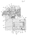
- FIG. 1 shows a camshaft phaser in a longitudinal section.
- the camshaft phaser is arranged at an end face of a camshaft 1 and serves to adjust the phase position, ie the rotational angular position of the camshaft 1 relative to a crankshaft of an internal combustion engine, for example a drive motor of a motor vehicle.
- the camshaft 1 is rotatably mounted about an axis of rotation R in a machine housing 2 of the internal combustion engine, for example in a cylinder head housing.
- the camshaft phaser comprises a stator 3, which can be rotated by the crankshaft, and a rotor 7, which can be connected in a rotationally fixed manner to the camshaft 1.
- the stator 3 is composed of a drive wheel 4, for example a sprocket, a cover 6 and an impeller 5 arranged axially between the drive wheel 4 and the cover 6.
- the drive wheel 4, the impeller 5 and the lid 6 are rotatably connected to each other.
- the assembly of the stator 3 is only an example.
- the stator 3 can also be composed of more than or instead of the three parts 4, 5 and 6 also of only two parts, for example of an integral part 4, 5 and the part 6 or the part 4 and a one-piece part 5, 6.
- the drive wheel 4 can be formed circumferentially on the outside of the impeller 5 and the cover area of the drive wheel 4, which laterally seals the stator-rotor arrangement, forms part of the rotor 7.
- the cover 6 may be part of the rotor 7.
- the stator 3 and the rotor 7 form a hydraulic swing motor.
- FIG. 3 shows the stator-rotor assembly 3, 7 in a cross section.
- the impeller 5 forms an outer component and the rotor 7 an inner component of the pivot motor.
- the hollow impeller 5 has at its inner periphery radially inwardly projecting wings 5a.
- the rotor 7 has radially outwardly projecting wings 7a, which form with the blades 5a of the stator 3 first control chambers 8 and second control chambers 9.
- the adjusting chambers 8 are arranged in the circumferential direction in each case to one side and the adjusting chambers 9 in each case to the other side of the wings 7 a of the rotor 7.
- the rotor 7 rotates relative to the stator 3 in FIG FIG. 3 clockwise to maximum in the FIG. 3 assumed end position. If the adjusting chambers 9 are pressurized and the adjusting chambers 8 relieved in pressure, the rotor 7 rotates counterclockwise. The rotational movement relative to the stator 3 in one direction of rotation corresponds to an overfeed and the relative rotational movement in the other direction to a lag of the camshaft 1 relative to the crankshaft.
- the adjusting chambers 8 are early adjusting chambers and the adjusting chambers 9 are late setting chambers.
- FIG. 3 takes the rotor 7 relative to the stator 3, the early position in which the camshaft leads relative to 1 of the crankshaft. If, instead, the late setting chambers 9 are acted on by the pressure fluid and the early adjusting chambers 8 are relieved, the rotor 7 rotates in the direction of lag until at most a retarded position.
- the early position and the late position are each specified by a stop contact. In each of the two end or extreme positions, at least one of the rotor blades 7a is in a stop contact with one of the stator blades 5a.
- the rotor 7 can not only be rotated back and forth relative to the stator 3 between these two rotational angle end positions, but can also be hydraulically fixed in any intermediate position by appropriate pressurization of both the early adjustment chambers 8 and the late adjustment chambers 9.
- the camshaft phaser has a control valve centrally arranged with respect to the stator-rotor arrangement 3, 7, with a valve housing 10 and a valve piston 20 which is arranged axially to and fro in an adjustable way in the valve housing 10 (FIG. Fig. 1 ).
- the valve piston 20 is hollow with an axially extending cavity 21, a piston inlet 22 at one axial end and a piston outlet 23, which leads radially through a jacket of the valve piston 20 surrounding the cavity 21.
- the valve piston 20 has at its side facing away from the piston inlet 22 the other axial end of a coupling member 25 for a coupling with an actuator 15, which causes the axial displacement of the valve piston 20.
- the coupling member 25 acts as an actuating tappet of the valve piston 20.
- the coupling member 25 may be integrally formed with the piston skirt surrounding the cavity 21 in one piece or optionally be axially fixed with this. It protrudes at the front end of the valve piston 20, which faces the actuator 15 axially.
- the coupling member 25 extends through an end closure wall 11 of the valve housing 10. The end closure wall 11 surrounds the coupling member 25 in close fitting and thus ensures in spite of the reciprocating coupling member 25 for the fluid-tight closure of the valve housing 10th
- the actuator 15 is an electromagnetic actuator, in the embodiment, a Axialhub electromagnet, with a current-carrying coil 16 and an armature 17, which surrounds the coil 16.
- the coil 16 is rotatably connected to the engine housing 2 of the internal combustion engine.
- the coil 16 is rotatably connected to a cover 2b, which in turn is fixedly connected to a mounted on the machine housing 2 mounting housing part 2a.
- the armature 17 is axially movable relative to the coil 16. It is with the coupling member 25 directly in a coupling engagement, which is formed as an axial pressure contact.
- the armature 17 When energizing the coil 16 acts on the armature 17 an axially directed towards the coupling member 25 actuating force acting on the coupling member 25 and thus on the valve piston 20 in the coupling engagement, a pure axial pressure contact. At the point of separation between the valve piston 20 rotating with the camshaft 1 during operation and the non-rotating actuator 15, preferably only point contact prevails.
- the armature 17 preferably has a spherical surface at its end contacting the coupling member 25.
- the coupling member 25 may have a spherical surface at its front end.
- the contact end of the armature 17 is formed as a ball sliding bearing by a ball in a pan of the armature 17 is freely rotatably mounted there.
- the control valve comprises a spring member 14 whose spring force counteracts the actuating force of the actuator 15.
- the spring member 14 is supported directly on the valve housing 10 and in the direction of the actuator 15 on the valve piston 20.
- the actuator 15 is driven by a control of the internal combustion engine, namely energized.
- the control is preferably carried out via a stored in a memory of the engine control map, for example, depending on the speed of the crankshaft, the load or other or other relevant for the operation of the internal combustion engine parameters.
- the valve piston 20 is arranged in a central axial cavity of the valve housing 10 in the manner explained back and forth movable. It has at its end facing away from the end closure wall 11 of the axial end of an axial, central leading into the housing cavity housing inlet P a, which can be fed via the camshaft 1, namely, a pressure inlet P of the camshaft 1, fluid under pressure.
- the fluid may in particular be a lubricating oil serving for lubricating the internal combustion engine, which also serves for lubricating, for example, the track bearing of the camshaft 1.
- the pressurized fluid is supplied to the control valve by way of example as preferred by the thrust bearing of the camshaft 1, that is, the pressure port P is connected to the lubricating oil supply for the thrust bearing.
- This pressurized fluid flows into the camshaft 1 at P, through the axial housing inlet P a into the valve housing 10 and through the piston inlet 22 in axial alignment with the housing inlet P a into the cavity 21.
- a piston outlet 23 through which the pressurized fluid is supplied depending on the axial position of the valve piston 20 either the Vietnamesestellhuntn 8 or the bossstellhuntn 9 to the phase position of the rotor 7 relative to the stator. 3 and thus to adjust the phase angle of the camshaft 1 relative to the crankshaft.
- the piston outlet 23 is formed by radial passages distributed over the circumference of the valve piston 20 through the jacket of the valve piston 20.
- the piston outlet 23 is arranged in an axially central portion of the valve piston 20.
- the valve housing 10 has through its jacket leading connections for the supply and discharge of the fluid to and from the adjusting chambers 8 and 9. These are a working connection A and a working connection B, a reservoir connection T a assigned to the working connection A and a reservoir connection T B assigned to the working connection B.
- the connections A to T B are in each case straight passages through the jacket of the valve housing 10.
- the connections A, B and T A extend radially over the shortest path through the jacket.
- the reservoir port T B extends obliquely outward into the phaser housing 2 a.
- the working port B of the valve housing 10 is arranged distributed over the circumference of the valve housing 10, radially extending and therefore short passages formed by the jacket of the valve housing 10.
- the terminals A, T A and T B are also each formed by a plurality of distributed around the central axis R arranged passageways.
- FIG. 1 shows the valve piston 20 in a first axial piston position in which it holds the spring member 14.
- the piston outlet 23 is connected to the working port B.
- the pressure fluid supplied via the pressure port P of the camshaft 1 flows in the axial direction through the axial housing inlet P a and the piston inlet 22 into the cavity 21 of the valve piston 20 and from there through the branching piston outlet 23 to that shown in FIG FIG. 1
- the adjusting chambers 8 associated with the working connection A are connected via the working connection A and a recess 26 formed on the outer circumference of the valve piston 20 to the reservoir connection T A and via this and a return 4 'rotating with the camshaft 1 connected to the reservoir and thus relieved in pressure.
- the recess 26 extends 360 ° circumferentially about the outer circumference of the valve piston 20. From the recess 26 from the rear seen in the axial direction behind the piston outlet 23, a further axially extending recess 27 is formed on the outer periphery of the valve piston 20, which also extends beyond the outer Extending circumference of the valve piston 20 circumferentially.
- the recess 27 is connected to the reservoir port T B in the first piston position.
- the reservoir port T B is assigned to the working port B. However, in the first piston position it is fluidically separated from the working port B by means of a sealing web of the valve piston 20 formed between the piston outlet 23 and the recess 27.
- the actuator 15 pushes the valve piston 20 from the illustrated first piston position axially in the direction of the housing inlet P A and with correspondingly large actuating force to an axial second piston position, in which no longer the working port B, but the other working port A is connected to the piston outlet 23.
- a sealing web of the valve piston 20 formed between the piston outlet 23 and the recess 26 separates the working port A from the associated reservoir port T A , so that in the second piston position the actuating chambers 9 are acted upon by the pressure fluid.
- the recess 27 connects the working port B with the reservoir port T B , so that the fluid can flow out of the adjusting chambers 8 and these are relieved of pressure.
- the rotor 7 moves accordingly in the illustration of FIG. 3 counterclockwise relative to the impeller 5 and thus to the stator 3.
- the rotatably connected to the rotor 7 camshaft 1 is adjusted in its phase position relative to the crankshaft by the same rotational angle.
- the high-pressure side fluid flowing into the control valve through the housing inlet P a urges the valve piston 20 with a first axial force acting in the direction of the actuator 15.
- a first axial force of the valve piston 20 in the direction of the actuator 15 can be flowed through, so that at its the actuator 15 facing rear between this back and the end closure wall 11, a fluid pressure builds up on the back of the valve piston 20, a counterforce, a second Exerts axial force. Since the projected by the pressurized fluid projection surface is reduced by the cross-sectional area with which the coupling member 25 protrudes through the end closure wall 11, the axial counterforce, the second axial force corresponding to the cross-sectional area of the coupling member 25 would be less than the first axial force.
- the valve piston 20 has a radially expanded piston portion 28, in the following widening 28, and the valve housing 10 has a suitably widened housing portion 18, which surrounds the widening 28 in a tight fit.
- the valve piston 20 at its outer periphery with the exception of the expansion 28, for example everywhere the same cylindrical cross-section.
- the valve piston 20 seen from the housing inlet 22 has an axial position behind the piston outlet 23 Feeder 24, which is formed by a plurality of distributed around the central axis R through channels, which are formed in a valve piston bottom.
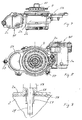
- the widening 28 and corresponding to the housing section 18 are dimensioned such that the enlargement of the projection surface F 28 facing the actuator 15 due to the widening 28 compensates at least a predominant part of the cross-sectional area F 25 of the coupling element 25 "lost" for the compensation ( FIG. 2 ).
- the compensation surface is an outer ring surface of the projection surface F 28 .
- the projection surfaces which each generate an axial force when the valve piston 20 flows through are of the same size in both axial directions.
- the expansion 28 is preferably formed on the actuator 15 facing the front end of the valve piston 20.
- the widened housing portion 18 has a sufficient axial extent to allow the adjustment movements of the valve piston 20.
- the widening 28 forms the end of the recess 27 facing the actuator 15.
- the widened housing section 18 tapers at 13 onto the narrower cross section, which is constant in the further axial course.
- the taper 13 is formed within the recess 27, axially by way of example in the region of the reservoir port T B.
- the phase adjuster comprises a locking device 30, which mechanically fixes the rotor 7 in a specific rotational angle position relative to the stator 3 in a locking engagement. As an example, it fixes the rotor 7 as preferred in the early position.
- the locking device 30 can be brought out of the locking engagement in a release state. If the locking device 30 is in the release state, the rotor 7 can rotate relative to the stator 3 when pressure is applied to either the control chambers 8 or the control chambers 9 and corresponding pressure relief of the respective other control chambers 9 or 8, ie changes the rotational angular position of the rotor 7 relative to the stator 3 become.
- Entriegelungsemindest horrin P E is required for unlocking against a spring force Entriegelungsemindest horrin P E is required.
- the unlocking minimum pressure P E is in preferred embodiments at most as large as the hot idle pressure P HL in the pressure fluid supply to the phaser.
- the hot idling pressure P HL can be measured, in particular, at a back-up device which is arranged in the pressure fluid supply in the vicinity of the phaser in order to prevent backflow of the pressure fluid from the phaser then, when the pressure in the pressure chambers acted upon with the pressurizing fluid 8 or 9 is higher than the supply pressure immediately upstream of the remindsperr issued.
- the remindsperr Marie can be formed in particular by a check valve.
- the locking device 30 comprises a relative to the stator 3 and rotor 7 axially reciprocable locking pin 31 and a locking spring 32 which biases with its spring force the locking pin 31 in an axial direction in the locking engagement.
- the locking pin 31 is supported on the rotor 7 via the locking spring 32 and guided axially reciprocally in a guide 36 in one of the rotor blades 7a. In the locking engagement, it protrudes axially beyond an end face of the respective rotor blade 7a into an axially opposite receptacle 33 of the stator 3.
- the receptacle 33 is formed as a recess on a rotor 7 facing end side of the stator 3, for example in the lid portion of the drive wheel 4.
- Die Verriegelungs resonance 30 is connected to either one of the adjusting chambers 8 or the adjusting chambers 9, preferably only one of the ceremoniesstellhuntn 8, so that when pressure is applied to the corresponding adjusting chambers of the locking pin 31 against the spring force of the locking spring 32 moves out of the locking engagement and the mechanical fixation of the rotor 7 solved becomes.
- the space in the rotor 7, in which the locking spring 32 is arranged, is connected via a discharge line 39 to the low-pressure side of the pressurized fluid system, so that the locking pin 31 of the receptacle 33 axially opposite can not build up unlocking preventing back pressure.
- FIG. 2 shows the phaser in the unlocked state.
- the unlocking minimum pressure P E is reached or exceeded, so that the rotor 7 can be hydraulically adjusted by means of the control valve.
- the rotor 7 is already no longer in the early position.
- the locking pin 31 forms a stepped piston with a guide portion 31 a, which is always guided in the rotor blade 7 a, and a contrast slimmer engagement portion 31 b, which in the in FIG. 5 shown locking engagement engages the receptacle 33 of the stator 3.
- Locking pin 31 has a pressure surface 31d in locking engagement with receiver 33d and a further annular pressure surface 31c remote therefrom.
- the pressure surfaces 31c and 31d act in the same direction.
- the pressure surface 31c closes an annular pressure space 37, which is formed inside the rotor 7a, at an end face.
- the receptacle 33 is connected to the pressure space 37 via a connecting channel 38, which is connected with respect to the locking device 30, so to speak, is short-circuited.
- the connecting channel 38 extends in the rotor blade 7a to the front side of the rotor 7 through a narrower guide portion of the guide 36, which engages closely the engaging portion 31b of the locking pin 31, so that the locking pin 31 not only in its wider portion 31a, but also in the engaging portion 31b is guided.
- the circumferentially bounded by the guide 36 space is closed at its opposite in the locking engagement of the receptacle 33 end by means of an inserted support member 35.
- the locking spring 32 is supported with a spring end on the support element 35 and with its other spring end on the locking pin 31.
- a vent passage 39a is formed, which connects the space between the support member 35 and locking pin 31 with the secondary lead 39, which is connected to the low pressure side of the pressure fluid system, so that can not build up the unlocking significantly obstructing backpressure.
- the locking device 30 is connected for unlocking with the nearest early setting chamber 8 through a connecting channel 34.
- the connecting channel 34 leads from the pressure chamber 37 through the rotor blade 7a directly into the early adjustment chamber 8 and closes it with the locking device 30 advantageously short.
- the pressure chamber 37 is therefore connected to the early setting chamber 8 in a particularly low-resistance manner, so that its pressure is virtually free from loss and distortion in the pressure chamber 37 and also via the inner connecting channel 38 in the receptacle 33 when the pressure changes.
- the inner connecting channel 38 is, as in the FIGS. 3 and 4 can be seen, advantageously groove-shaped in the guide 36 in a radial with respect to the axis of rotation R range, for example, outside arranged.
- the required for receiving the lateral force circumferential surface of the guide 36 is reduced as little as possible.
- the arrangement of the locking device 30 near the radial end of the rotor blade 7a as this contributes to the reduction of the transverse force to be absorbed. At the same drag torque would cause a more central arrangement, closer to the axis of rotation of the rotor 7, the reduction of the lever corresponding to a larger lateral force.
- An advantage is an eccentric arrangement with respect to the circumferential direction of the locking device 30 in the rotor blade 7a.
- the locking device 30 is arranged in this eccentric arrangement in the circumferential direction closer to the side surface of the rotor blade 7a delimiting the early adjustment chamber 8 than in the side area which is opposite in the circumferential direction and delimits the late setting chamber 9. If the late setting chamber 9 is acted upon to adjust the rotor 7 in the direction of the late position, there is a comparatively long sealing web between the late setting chamber 9 and the locking device 30, in particular on the side of the stator 3 on which the receptacle 33 is arranged.
- the rotor blade 7a receiving the lock pin 31 is wider in the circumferential direction than the other rotor blades 7a.
- FIG. 3 also shows the short and direct fluid connections 7b, which lead from the central control valve 10, 20 through the rotor 7 to the control chambers 8 and 9, respectively.
- the FIG. 3 These are the fluid connections 7b to the working ports A for the late adjustment chambers 9.
- the fluid connections leading from the control valve to the ceremoniestellhuntn 8 are axially and circumferentially offset from the fluid connections 7b and extends.
- the Fluid connections 7b and also the fluid connections for the early adjustment chambers 8 are straight, at least substantially radially extending holes which open at their radially inner ends to the valve housing 20 and at their outer ends in the root regions of the rotor blades 7a in the respective control chamber 8 and 9 respectively.
- FIG. 6 shows the phaser with an associated pressure storage device 40.
- the pressure storage device 40 has a storage chamber 41 and a movable wall structure 42, which limits the storage chamber 41 on one side. Furthermore, it has a spring device 43 against whose restoring spring force the wall structure 42 for filling the storage chamber 41 is movable.
- the wall structure 42 is formed as a piston.
- the spring device 43 consists of a single mechanical spring, by way of example as preferred of a claimed when loading the storage chamber 41 to pressure coil spring.
- the wall structure 42 is freely movable back and forth, so that their chamber pressure is always distortion-free available in the at least partially filled state.
- the pressure storage device 40 is arranged in the flow path of the pressurized fluid to the phaser upstream of the control valve 10, 20.
- the phaser is connected via a feed channel 50 to the pressurized fluid system.
- a feed channel 50 In the feed channel 50 is aradsperr adopted 51, for example a check valve, upstream of the phaser and the pressure storage device 40 is arranged, which prevents a backflow of pressurized fluid.
- a filter element 52 is also disposed between the remindsperr issued 51 and the storage chamber 41.
- the restraining device 51 opens in the direction of the pressure storage device 40, so that this corresponding to the pressure and can partially or completely fill the restoring spring force of the spring device 43.
- the maximum filling volume is reached when the wall structure 42 abuts against a stop of the pressure storage device 40.
- the storage chamber 41 is connected via a short path via a downstream downstream feed channel 53 with the phaser. In the exemplary embodiment, the connection is made via the camshaft 1.
- Via a discharge channel 46 ensures that the storage chamber 41 can fill without significant backpressure.
- the discharge channel 46 connects the space at the rear of the movable wall structure 42 with the low pressure side of the pressurized fluid supply system.
- the storage chamber 41 is covered at an open side by a lid 2c.
- the lid 2c forms as preferred, but only by way of example, a stop for the piston 42 and the other as preferred, but also only by way of example, an inlet 2d leading directly into the storage chamber 41 and an outlet 2e leading directly from the storage chamber 41.
- the Storage chamber 41 is connected to the feed channel 50 via inlet 2d and to downstream feed line 53 leading to phaser via outlet 2e.
- the feed channel 53 extends as preferred, but only as an example along the storage chamber 41, in the example parallel to the direction of movement of the piston 42, and to the lid 2c, where it opens into the outlet 2c.
- the pressure storage device 40 is arranged in a leading to the phaser main flow of the pressurized fluid by the example by way of the machine housing 2 and the connected feed channel 50 supplied pressurized fluid only via the pressure storage device 40 while flowing through the storage chamber 41 in the advancing to the phaser feed channel 53 and this example again passes through the machine housing 2 to the pressure port P.
- Control valve leading supply channel 53 connects, be formed on the cover 2c facing the end face of the attachment housing 2a, for example, as one or a respective groove-shaped recess on the lid 2c facing the end of the storage chamber 41 surrounding wall. It is merely necessary to ensure that a certain space remains between the piston 42 and the cover 2c, which space is connected to the supply channel 50 or the supply channel 53 via the inlet or outlet formed in such an alternative manner.
- This solution offers cost advantages in the production, since the lid 2c in such embodiments on its the storage chamber 41 facing end face can be easily plan formed.
- the acted upon by the pressurized fluid in the storage chamber 41 surface of the wall structure 42 and the spring stiffness and optionally an existing without pressurization spring preload of the spring means 43 are tuned to the system pressure in the pressurized fluid supply system that the storage chamber 41 begins to fill at the latest when in the pressurized fluid supply system, the hot idle pressure P HL is reached.
- the Grebeginntik P FB is the pressure at which the filling begins, ie in which the wall structure 42 is moved against the restoring spring force of the spring means 43 and an increase in the filling volume against a minimum volume of the storage chamber 41 begins.
- the minimum volume may be zero, but in practice the storage chamber 41 will have some residual volume in the initial state.
- the Grebeginntik P FB is at most as large as the hot idling pressure P HL , preferably it is smaller.
- the pressure storage device 40 thus becomes effective even at low system pressures.
- the pressure storage device 40 is further designed so that the filling of the storage chamber 41 is not completed when the pressure in the storage chamber 41 corresponds to the hot idle pressure P HL , ie at idle speed, but only at a higher inflation pressure.
- the Pressure accumulator 40 thus operates out of the hot idle, preferably even at a lower speed than the idle speed, up to a lying above the idle speed always with adjusted compensation or accumulator pressure.
- the pressure storage device 40 is tuned so that the storage chamber 41 reaches its maximum fill volume at the earliest at double idle speed, more preferably at least three times idle speed.
- the maximum filling volume can be absolutely limited as in the embodiment by a stop contact, in principle, however, a stop limit is not required.
- the pressure storage device 40 can also fill or empty corresponding to the respective system pressure over the entire speed range of the internal combustion engine.
- filling over the entire speed range is not required and not always desirable because the spring device 43 is subject to limitations in terms of its spring rigidity. Such limitations can be counteracted by a series or parallel connection of several spring members, for example, a spring member low spring stiffness and a stiffer spring member, wherein in the lower speed range primarily the softer spring member and at higher speed the stiffer spring member only to a relevant extent or at all first would tension.
- the locking device 30 is tuned by appropriate design of the pressure surfaces 31c and 31d of the locking pin 31 and the spring stiffness or a spring bias of the locking spring 32 to the system pressure so that the Entriegelungsemindesttik P E also at most as large as the hot idling pressure P HL , preferably smaller than this , More preferably, the unlocking minimum pressure P E is at most as large as the filling start pressure P FB , preferably smaller than this.
- the comparatively low unlocking minimum pressure P E ensures early unlocking, at low speeds of the internal combustion engine, and thus already an adjustability of the rotor at a correspondingly low speed.
- Such a sensitive unlocking counteracts when the locking device 30 with the in the ceremoniestellkanimer 8 ( FIG. 3 ) prevailing pressure is unlocked, the application of both pressure surfaces 31c and 31d at the same time further favoring acts, as a result, the spring force of the locking spring 32 can be selected correspondingly high, resulting in a secure locking engagement result.
- the hot idling pressure P HL can be measured, in particular close to the restraint device 51, in particular upstream of it.
- the filling start pressure P FB and the minimum filling pressure for a complete filling can be measured in the same place, assuming of course that the pressure in the storage chamber 41 at the time of measurement is not just greater than the pressure in front of the remindsperr owned 51.
- the minimum unlocking pressure P E can also be measured there. The locking engagement should be released when the unlocking minimum pressure P E is reached at said point.
- FIG. 7 shows the attachment housing with the attachment housing part 2a and the covers 2b and 2c, which receives the phaser, substantially the stator 3, the rotor 7 and the central control valve from which the valve housing 10 protrudes on the mounting side of the attachment housing 2a, 2b, 2c.
- the attachment housing for example the attachment housing part 2a, also includes the same pressure accumulator device 40, so summarizes the phaser and the pressure storage device 40 together to form a mounting unit.
- This mounting unit is mounted on the engine housing of the internal combustion engine, for example on a cylinder head housing, with the cover removed 2b, which is mounted after mounting on the housing part 2a.
- the remindsperr worn 51 is advantageously also in the mounting housing 2a, 2b, 2c arranged.
- FIG. 8 shows the attachment housing 2a, 2b, 2c in an end view of the mounting side.
- a seal 56 is arranged, which ensures in the assembled state for the seal between the machine housing and the mounting housing 2a, 2b.
- centering elements 57 protrude beyond the seal 56, relative to the mounted state, in the direction of the machine housing and, in the assembled state, into adapted centering counter-structures of the machine housing.
- the centering elements 57 are illustrative pin-shaped and can be hollow in cross section and formed in such embodiments as centering.
- the centering elements 57 serve not only to center and thereby facilitate assembly, but also keep the seal 56 on the mounting side of the attachment housing 2a, 2b in an immediately suitable for mounting location by the seal 56 with at least one of the centering 57, preferably with several or all centering elements 57, in a holding engagement, for example in a rear grip. In holding engagement, the seal is captively connected to the mounting housing.
- FIG. 9 shows such a rear handle representative of preferably one or more others.
- the illustrated centering element 57 extends through an opening of the seal 56.
- the centering element 57 is in the attachment housing 2a, 2b inserted, is held firmly in a corresponding receptacle and protrudes as I said about the end face of the attachment housing 2a, 2b a bit far ahead. Close to the end face it is fitted in the protruding section, so that the seal 56 engages with its centering element 57 surrounding the opening edge 58 in the sidecut and so the seal 56 holding the rear handle is formed.
- the waist can be replaced by another retaining engagement element such as a projection such as a flange.
- the functions of centering the attachment housing 2a, 2b and the holder of the seal 56 and the creation of the actual joint connection of mounting housing 2a, 2b and machine housing are concentrated in a confined space by a clamping element 59 of the joint connection, by the hollow centering 57, an example Screw, is guided.
- the clamping element 59 extends through the centering element 57 and is connected in its projecting portion with the machine housing, for example in a screw engagement 2f.
- FIG. 10 shows the locking device 30 again in longitudinal section.
- the locking pin 31 is in locking engagement and is retracted with maximum engagement length L 31 in the receptacle 33. Due to the cylindrical or optionally also with a very acute angle of, for example, 2 ° or 3 ° conical circumference of the locking pin 31 acts blocking over its entire maximum engagement length L 31 in memorisswirk Scheme together with the receptacle 33.
- FIG. 11 shows an improved locking device 30 of a first modified embodiment in longitudinal section.
- This locking device 30 differs from the locking device 30 of FIGS. 1 to 10 only with respect to the locking pin, which is therefore provided with the reference numeral 60.
- the recording is also provided with a different reference numeral, the reference numeral 80, but corresponds to the receptacle 33 of FIGS. 1 to 10 .
- the locking pin 60 is retracted in the locking direction L, which coincides with a central longitudinal axis of the locking pin 60, in the receptacle 80 with maximum engagement length L 60 and lies in the locking direction L to stop.
- the stop is exemplified by a projecting at the bottom of the receptacle 80 flat elevation.
- the locking pin 60 tapers concisely in its engagement region extending over the maximum engagement length L 60 .
- the lock pin 60 has a front pin portion 61 and a rear pin portion 62 in its engagement portion.
- the front pin portion extends in the locking direction L to the front free end of the locking pin 60.
- the rear pin portion 62 is also dipped into the receptacle 80 in locking engagement and overlaps with the opening edge 83 of the receptacle 80. It extends in locking engagement a distance in the direction to the free end of the locking pin 60.
- the engagement portion of the locking pin 60 is comprised of the two pin portions 61 and 62, which together extend beyond the maximum engagement length L 60 .
- Front pin section 61 has a length L 61 measured in the locking direction L
- the rear pin section 62 has a length L 62 whose sum corresponds to the maximum L 60
- the receptacle 80 also has an overlapping in locking engagement with the front Pinabrisk 61 lower receiving portion 81 of the length L 61 and a to the edge 83 of the receiving opening extending upper accommodating portion 82 having a length L 62 corresponding length. In the locking engagement thus overlap the front pin portion 61 with the lower receiving portion 81 and the rear pin portion 62 with the upper receiving portion 82nd
- the front pin portion 61 has over its entire length L 61 on the outer circumference on an inclination ⁇ to the locking direction L, which is so large that the locking pin 60, should he press in the region of the front pin portion 61 against the opening edge 83, not clamp and a Self-locking of pin 60 and receptacle 80 can not take place, but the locking pin 60 is pressed in the force exerted by the rotor 7 transverse force against the spring force in the direction of the release position. By dipping only with the front pin portion 61, therefore, the rotor 7 can not be blocked relative to the stator 3.
- the relative rotational movement blocking blocking contact can reach only the rear pin portion 62, which may be tapered cylindrical or slightly conical with a very small cone angle of, for example, 3 ° or 4 ° to the free end of the locking pin 60 for this purpose.
- a blocking contact of the front pin portion 61 is prevented by the large inclination ⁇ , which is preferably at least 45 °.
- the inclination ⁇ is preferably at most 80 °. Slopes are particularly favorable by 60 °, namely from the range of 60 ° ⁇ 10 °.
- the inclination values apply in each case to the entire length L 61 of the front pin section 61.
- the inclination ⁇ may be variable, but the inclination ⁇ is preferably constant over the length L 61 and the pin section 61 is correspondingly conical on the outer circumference.
- the front pin portion 61 is a truncated cone by the front end of the locking pin 60 is formed as a planar end face.
- the rotor 7 is now to be adjusted in the direction of the retarded position, two movements can take place simultaneously when reversing: because of the pressure reduction in the early adjustment chambers 8 and the pressure build-up in the late adjustment chambers 9, the rotor 7 begins to rotate relative to the stator 3 in the direction of the retarded position , If the early-acting chambers 8 are relieved of pressure, the locking pin 60 starts driven out by the spring force, and there is the possibility that it dips into the receptacle 80. Depending on which of the two Movements is the faster, therefore finds a locking or adjustment of the rotor 7 instead. Although the locking pin 60 may initially dip easily into the receptacle 80 because of the significantly large length L 61 and the large inclination ⁇ .
- the locking pin 60 can be urged back in the direction of the release position in cooperation of front pin portion 61 and opening edge 83 by the transverse force exerted by the rotor 7 against the locking direction 2. Since the system of locking pin 60 and locking spring 32 is subject to a certain inertia, the time required for the extension by the length L 61 L is sufficient to prevent jamming of locking pin 60 and receptacle 80 safer than conventional locking pins.
- the pressure at which the rotor 7 can still be reliably adjusted relative to the stator 3 is reduced. It ensures a more reliable reversal in the pressure chamber connected to the control chamber at low pressure.
- the same advantage arises when starting the internal combustion engine. As a result of the fluid pressure that builds up in the process, the locking pin 60 only has to be pushed back by the length L 62 of the rear pin section 62 against the spring force. The risk of tilting due to shear forces is reduced.
- the tilt jump takes place advantageously within a very small length of preferably less than 10% and more preferably still less than 5% of the maximum engagement length L 60 or over a correspondingly small radius.
- the production can also be set up so that the inclination jump takes place as abruptly as possible in terms of manufacturing technology.
- the relatively sharp geometric separation into the two functionally different pin sections 61 and 62 as explained above enables unlocking when reversing the rotor 7 even at low pressures, but at the same time becomes too by the interaction of the rear pin portion 62 with the upper receiving portion 83 a secure blocking at not yet the pressure fluid filled phaser, in particular in start phases of the internal combustion engine, guaranteed. Because of the reduction of the minimum unlocking pressure required for unlocking, the unlocking can be ensured even in hot idle phases of the internal combustion engine safer than in the known locking devices. The availability of the phaser for camshaft adjusting operations is increased.
- the locking pin 60 corresponds to the locking pin 31, so that reference can be made to the relevant embodiments.
- reference numeral 63 is entered for the first printing surface.
- the second pressure surface 64 is formed by the inclined peripheral surface of the front pin portion 61, for the pressurization for unlocking apply the statements in connection with the locking pin 31, however, in the same way.
- the lengths L 61 and L 62 are preferably each at least 0.5 mm, more preferably at least 1 mm.
- the ratio of the length L 61 of the non-blocking acting pin portion 61 to the length L 62 of the blocking acting pin portion 62 is selected in appropriate embodiments in the range of 1 ⁇ 0.5.
- FIG. 12 shows a differently modified locking device 30, a second embodiment of the invention, in which a locking pin 70 is used, which the locking pin 31 of FIGS. 1 to 10 equivalent.
- this locking device 30 has a modified receptacle 90.
- the receptacle 90 comprises a lower receiving portion 91, which is formed as in the receptacles 33 and 80, and an upper receiving portion 92 which extends to the opening edge 93 of the receptacle 90 and widening towards this or from the opening edge 93 to the lower receiving portion 91 continuously tapers over its entire length.
- the length of the lower receiving portion 91 corresponds to the length L 71 of the front pin portion 71
- the length of the upper receiving portion 92 corresponds to the length L 72 of the rear pin portion 72, but the pin portions 71 and 72 continue each other continuously without inclination changes.
- the front pin portion 71, in particular the front free end of the locking pin 70, and the upper receiving portion 92 cooperate in the same manner as the front pin portion 61 and the upper receiving portion 82 of the first example.
- the front pin portion 71 acts in this embodiment, however with the lower receiving portion 91 in locking engagement together blocking.
- the Inclination at the outer periphery of the front pin portion 71 and the inclination at the inner periphery of the lower receiving portion 91 are correspondingly small.
- the said peripheral surfaces may in particular be cylindrical or conical with a slight inclination.
- the tapering of the locking pin or the receptacle according to the invention also has advantages over the functional advantages of the locking device with respect to the development of the phaser until it is ready for series production. If, for example, the locking pin and the receptacle are formed in the early stages of development with continuous cylindrical or slightly conical circumferential effective ranges and the locking spring 32 adapted, even in later development stages, for example in the test phase on the engine test bench or even later, a locking pin conventionally shaped up to that point be replaced by a locking pin according to the invention or a conventionally shaped receptacle by a recording according to the invention.
- the design of the locking spring 32 and the geometry of locking pin and recording moreover, nothing must be changed.
- FIG. 13 shows a locking device 30 of a third embodiment according to the invention with a modified locking pin 100 and a modified receptacle 110. From the longitudinal section of FIG. 13 is in FIG. 14 the area of the locking engagement is shown enlarged.
- the locking pin 100 has a front pin portion 101 and a rear pin portion 102 that form the engagement portion with which the locking pin 100 engages the receptacle 110 in locking engagement.
- the rear pin portion 102 tapers toward the free end of the locking pin 100.
- the pin portion 102 tapers over its entire length, the in FIG. 14 L 102 is tapered, conically everywhere with the same inclination.
- the cooperating in locking engagement with the pin portion 102 upper receiving portion 112 tapers congruent to the pin portion 102 toward the bottom of the receptacle 110, in the embodiment according to conical with anywhere the inclination of the rear pin portion 102 corresponding inclination.
- the lower receiving portion 111 has the same inclination as the upper receiving portion 112 almost to the bottom of the receptacle 110. This inclination is so small that the locking pin 100 is blocked in the locking engagement in the region of the pin portion 102.
- the front pin portion 101 has the pronounced strong inclination ⁇ , so that the locking pin 100 in the front pin portion 101 is not blocked.
- the comments on the other embodiments apply.
- the front pin portion 101 is shorter in relation to the rear pin portion 102 than in the two previous embodiments.
- the aspect ratio L 102 : L 101 that is, the length of the rear pin portion 102 to the length of the front pin portion 101, is about 5.
- the upper receiving portion 112 has, in an upper portion extending to the opening edge 113 and the opening edge 113, over a length L 113 , the in FIG. 14 is registered, an inclination which is significantly greater than the inclination in the adjoining lower portion of the upper receiving portion 112.
- the measured in the direction of movement of the locking pin 100 length L 113 is greater than it would be in a pure chamfering of the receptacle 114.
- the length L 113 with the comparatively large, ie, flat, slope is preferably at least one fifth of the total length L 100 of the engagement portion of the locking pin 100.
- the length L 101 of the front pin portion 101 and the length L 113 of the upper one Part of the upper receiving portion 112 at least substantially equal. If the locking pin 100 protrudes into the receptacle 110 only with its front pin section 101, a comparatively large clearance is thereby obtained in the transverse direction, ie in the direction of the relative rotational movement of the stator 3 and the rotor 7.
- phase adjuster corresponds to the exemplary embodiments already described above.
- the locking pin is formed in the illustrated embodiments as a stepped piston.
- the locking pin in all embodiments may instead be designed as a piston with a single-cylindrical guide, so that such a locking pin and a leading him in the locking and unlocking direction rotor 7 only have cylindrical guide circumferential surfaces.
- the external connection channel 34 which in the illustrated embodiments, the Vietnamese subcutaneous tissue service provider 8 and in alternative embodiments, the opposite handedstellhunt 9 connects directly to the locking device 30, open into a connecting channel 38 corresponding internal connection channel, which separates the pressurized fluid from the corresponding Entriegelungsstellhunt 8 or 9 in the respective receptacle and there against the pressure surface of the locking pin, for example, the locking pin 31, 60, 70 or 100, leads to effect the unlocking.
- a locking pin with only a single cylindrical guide is in terms of manufacturing and also to avoid over-determination in the guiding engagement of pin and rotor beneficial.
Landscapes
- Engineering & Computer Science (AREA)
- Mechanical Engineering (AREA)
- General Engineering & Computer Science (AREA)
- Valve Device For Special Equipments (AREA)
Description
Die Erfindung betrifft einen Nockenwellen-Phasensteller zur Verstellung der Drehwinkelposition einer Nockenwelle relativ zu einer Kurbelwelle einer Brennkraftmaschine und spezieller eine Verbesserung bezüglich einer Verriegelung und Entriegelung des Phasenstellers.The invention relates to a camshaft phaser for adjusting the rotational angular position of a camshaft relative to a crankshaft of an internal combustion engine, and more particularly to an improvement with respect to a locking and unlocking of the phaser.
Zur Erhöhung von Leistung und Drehmoment, aber auch zur Reduzierung des Kraftstoffverbrauchs und der Abgasschadstoffemissionen von Verbrennungsmotoren für Straßenfahrzeuge haben Nockenwellen-Phasensteller zur Variation der Einlass- und auch Auslasssteuerzeiten Verbreitung gefunden. Aufgrund der hohen Zuverlässigkeit, aber auch im Hinblick auf eine günstige Kosten-Nutzen-Relation haben sich hydraulische, durch das Schmieröl für die Brennkraftmaschine betätigte Phasensteller nach dem Prinzip des hydraulischen Schwenkmotors bewährt. Verschärfte Anforderungen an den Kraftstoffverbrauch und die Schadstoffemission erfordern hohe Stellgeschwindigkeiten. Zur Steigerung der Stellgeschwindigkeit, insbesondere bei niedrigem Schmieröldruck und niedriger Öltemperatur und entsprechend hoher Viskosität, sieht die
Die hydraulischen Phasensteller können beim Stillstand der Brennkraftmaschine leer laufen. Beim Starten der Brennkraftmaschine kann die mit dem Phasensteller zu verstellende Nockenwelle undefinierte Winkelpositionen einnehmen, bis der Phasensteller wieder vollständig befüllt ist. Hierdurch verschlechtern sich das Startverhalten und die Abgasschadstoffemissionen der Brennkraftmaschine. Zudem führt das ungleichförmige Drehmoment der Nockenwelle bei entleertem Phasensteller zu schlagenden Geräuschen. Zur Vermeidung dieser Effekte werden Nockenwellen-Phasensteller mit Verriegelungseinrichtungen versehen, die gewährleisten, dass die Nockenwelle beim Start der Brennkraftmaschine eine definierte Position in Relation zur Kurbelwelle einnimmt. Praktisch wird die Verriegelung durch einen beispielsweise im Rotor integrierten federbelasteten Verriegelungspin realisiert, der in eine Aufnahme des Stators eintaucht, also einriegelt, und gegen die Federkraft einer Verriegelungsfeder durch Beaufschlagung mit dem Druckfluid des Phasenstellers entriegelt wird. Ein Lösen der Verriegelung und eine dann mögliche Verstellung der Phasenlage der Nockenwelle sind erst möglich, wenn sich ein für die Verstellung der Nockenwelle ausreichender Druck im Druckfluidsystem aufgebaut hat. Insbesondere eine Auslegung der Verriegelungseinrichtung für eine Verriegelung der Nockenwelle in der "früh"-Winkelposition bereitet in der Praxis häufig Schwierigkeiten, da sich bei der Entriegelung das Schleppmoment der Nockenwelle und das Verstellmoment des Verstellers zur Verstellung der Nockenwelle in Richtung "spät" addieren und diese Drehmomente Verkantungskräfte auf den Verriegelungspin verursachen, wodurch die Entriegelung erschwert wird. Bei der Auslegung und Abstimmung der Verriegelungseinrichtung besteht daher ein Zielkonflikt bezüglich einer sicheren Entriegelung bereits bei sehr niedrigen Fluiddrücken und Nockenwellendrehzahlen einerseits und einer sicheren Verriegelung auch unter ungünstigen Randbedingungen wie etwa beim Kaltstart der Brennkraftmaschine bei leergelaufenem Phasensteller andererseits, insbesondere dann, wenn beim Abstellen der Brennkraftmaschine die Verriegelungsposition nicht angefahren wurde.The hydraulic phaser can run empty at standstill of the engine. When the internal combustion engine is started, the camshaft to be adjusted with the phaser can assume undefined angular positions until the phaser is completely filled again. As a result, the starting behavior and the exhaust gas pollutant emissions of the internal combustion engine deteriorate. In addition, the non-uniform torque of the camshaft with deflated phaser leads to beating noise. To avoid these effects camshaft phasers are provided with locking devices, which ensure that the camshaft occupies a defined position in relation to the crankshaft at the start of the internal combustion engine. Practically, the locking is realized by an example integrated in the rotor spring-loaded locking pin, which dips into a receptacle of the stator, so locks, and is unlocked against the spring force of a locking spring by acting on the pressurized fluid of the phaser. A release of the lock and then possible adjustment of the phase angle of the camshaft are only possible if a sufficient for the adjustment of the camshaft Built pressure in the pressure fluid system. In particular, an interpretation of the locking device for locking the camshaft in the "early" angular position is often difficult in practice, since in the unlocking the drag torque of the camshaft and the adjusting torque of the adjuster for adjusting the camshaft in the direction of "late" add and this Torque cause jamming forces on the locking pin, whereby the unlocking is difficult. In the design and vote of the locking device therefore there is a conflict of objectives with respect to a safe unlocking even at very low fluid pressures and camshaft speeds on the one hand and a secure locking even under unfavorable conditions such as the cold start of the engine with idle phaser on the other hand, especially when turning off the engine the locking position was not approached.
Aus der
Bei einem aus der
Die
Die
Die
Die
Es ist eine Aufgabe der Erfindung, einen Nockenwellen-Phasensteller mit einer Verriegelungseinrichtung zu schaffen, die den Phasensteller in Startphasen einer Brennkraftmaschine sicher verriegelt, aber ein Entriegeln auch bei niedrigen Drücken eines den Phasensteller beaufschlagenden Druckfluids, wie sie etwa im Leerlauf der betriebswannen Brennkraftmaschine auftreten, mit größerer Sicherheit gewährleistet, so dass auch die Gefahr reduziert wird, dass sie im falschen Moment verriegelt, wenn der Rotor des Phasenstellers beispielsweise aus der verriegelbaren Drehwinkelposition verstellt werden soll.It is an object of the invention to provide a camshaft phaser with a locking device which securely locks the phaser in start phases of an internal combustion engine, but unlocking even at low pressures of a pressure fluid acting on the phaser, such as occur during idling of the engine internal combustion engine, ensured with greater security, so that the risk is reduced that it locks at the wrong moment, if the rotor of the phaser is to be adjusted, for example, from the lockable rotational angle position.
Die Erfindung geht von einem Nockenwellen-Phasensteller zur Verstellung der Drehwinkelposition einer Nockenwelle relativ zu einer Kurbelwelle einer Brennkraftmaschine aus, der einen von der Kurbelwelle in vorzugsweise fester Drehzahlbeziehung drehantreibbaren Stator und einen vom Stator drehantreibbaren und zum Drehantreiben der Nockenwelle mit dieser koppelbaren Rotor umfasst. Im montierten Zustand wird der Stator von der Kurbelwelle drehangetrieben und treibt auf den Rotor ab, der wiederum mit der Nockenwelle gekoppelt ist und dadurch die Nockenwelle drehantreibt. Der Stator kann insbesondere mit einem Antriebsrad eines Zugmitteltriebs, beispielsweise Ketten- oder Zahnriementriebs, oder eines Zahnradtriebs, drehmomentfest verbunden sein, wobei das Antriebsrad vorzugsweise ein fester Bestandteil des Stators ist. Der Rotor ist im montierten Zustand drehmomentübertragend, vorzugsweise drehfest, mit der Nockenwelle verbunden, also für solch eine Montage eingerichtet.The invention is based on a camshaft phaser for adjusting the rotational angular position of a camshaft relative to a crankshaft of an internal combustion engine comprising a rotatably driven by the crankshaft in preferably fixed speed relationship stator and a rotatably driven by the stator and rotatably driving the camshaft with this coupled rotor. When assembled, the stator is rotationally driven by the crankshaft and drives on the rotor, which in turn is coupled to the camshaft and thereby rotatably drives the camshaft. The stator may in particular be connected torque-tightly to a drive wheel of a traction drive, for example a chain drive or a toothed belt drive, or a gear drive, the drive wheel preferably being an integral part of the stator. The rotor is in the assembled state torque transmitting, preferably non-rotatably connected to the camshaft, so set up for such a mounting.
Der Nockenwellen-Phasensteller weist wenigstens eine Frühstellkammer zur Erzeugung eines auf den Rotor relativ zum Stator in Richtung Voreilung wirkenden Drehmoments und wenigstens eine Spätstellkammer zur Erzeugung eines auf den Rotor in die Gegendrehrichtung relativ zum Stator in Richtung Nacheilung wirkenden Drehmoments auf. Vorzugsweise umfasst der Phasensteller mehrere Frühstellkammern und mehrere Spätstellkammern, um die zur Erzeugung des jeweiligen Drehmoments erforderliche Kraft um die Drehachse des Rotors gleichmäßig und auf eine größere Druckfläche zu verteilen. Für die Verstellung der Drehwinkelposition des Rotors in Richtung Frühstellung bzw. Voreilung ist die wenigstens eine Frühstellkammer oder sind die bevorzugt mehreren Frühstellkammern gemeinsam mit dem Druckfluid beaufschlagbar und die wenigstens eine Spätstellkammer oder die bevorzugt mehreren Spätstellkammern in Bezug auf den Druck entlastbar. Das Umgekehrte gilt für eine Verstellung des Rotors in Richtung Spätstellung bzw. Nacheilung. In bevorzugten Ausführungen sind die Früh- und Spätstellkammer(n) mittels einer Regelungseinrichtung auch derart wechselseitig mit dem Druckfluid beaufschlagbar, dass der Rotor nicht nur in einer der beiden oder in den beiden Endpositionen, der Frühstellung oder der Spätstellung, sondern auch in einer Drehwinkelzwischenposition, von beiden Endpositionen beabstandet, geregelt eingestellt werden kann.The camshaft phaser has at least one early setting chamber for generating a torque acting on the rotor in the direction of advance relative to the stator and at least one late setting chamber for generating a torque acting on the rotor in the reverse direction of rotation relative to the stator in the direction of lag. Preferably, the phaser comprises a plurality of Frühstellkammern and a plurality of Spätstellkammern to distribute the force required to generate the respective torque about the axis of rotation of the rotor uniformly and on a larger pressure surface. For the adjustment of the rotational angular position of the rotor in the direction of advance position or advance, the at least one early setting chamber or the preferably a plurality of Frühstellkammern be acted upon together with the pressurized fluid and the at least one Spätstellkammer or preferably several Spätstellkammern relieved in relation to the pressure. The reverse applies to an adjustment of the rotor in the direction of late or lag. In preferred embodiments, the early and late setting chamber (s) by means of a control device so mutually acted upon by the pressurized fluid that the rotor not only in one of the two or in the two end positions, the early position or the late position, but also in a rotational angle intermediate position, spaced from both end positions, can be adjusted regulated.
Das Druckfluid kann in Abhängigkeit von der Drehzahl der Kurbelwelle gefördert werden, so dass sein Druck mit der Drehzahl der Kurbelwelle steigt. Die Abhängigkeit kann beispielsweise derart sein, dass der Druck des Druckfluids der Drehzahl quasi ständig folgt, im Extremfall kontinuierlich, die Abhängigkeit kann aber auch so gestaltet sein, dass der Druck des Druckfluids bei steigender Drehzahl der Kurbelwelle nur in diskreten Schritten, in Stufen, gegebenenfalls auch nur in einer einzigen Stufe steigt. Das Druckfluid wird in bevorzugten Ausführungen mittels einer Verdrängerpumpe gefördert, die von der Brennkraftmaschine in Abhängigkeit von der Drehzahl der Kurbelwelle angetrieben wird. Der Phasensteller ist für die Zuführung des Druckfluids zu den Stellkammer an eine Hochdruckseite eines Druckfluidsystems und für die Abführung des Druckfluids aus den Stellkammern an eine Niederdruckseite des Druckfluidsystems anschließbar.The pressurized fluid may be delivered in response to the rotational speed of the crankshaft so that its pressure increases with the speed of the crankshaft. The dependence can for example be such that the pressure of the pressure fluid quasi constantly follows the speed, in the extreme case continuously, but the dependence can also be designed so that the pressure of the pressure fluid with increasing speed of the crankshaft only in discrete steps, in stages, if necessary even in a single step rises. The pressurized fluid is conveyed in preferred embodiments by means of a positive displacement pump, which is driven by the internal combustion engine in dependence on the rotational speed of the crankshaft. The phase adjuster can be connected to a high-pressure side of a pressurized fluid system for supplying the pressurized fluid to the actuation chamber and to a low-pressure side of the pressurized fluid system for discharging the pressurized fluid from the actuation chambers.
Bei dem Druckfluid kann es sich insbesondere um ein der Schmierung der Brennkraftmaschine dienendes Schmieröl handeln. Die Vorrichtung kann entsprechend in einem Schmierölversorgungssystem der Brennkraftmaschine angeordnet sein, das in diesem Fall das Druckfluidsystem bildet.The pressurized fluid may in particular be a lubricating oil serving to lubricate the internal combustion engine. The device may accordingly be arranged in a lubricating oil supply system of the internal combustion engine, which in this case forms the pressurized fluid system.
Der Phasensteller umfasst eine Verriegelungseinrichtung, die zwischen einem Verriegelungszustand und einem Freigabezustand wechseln kann. Im Verriegelungszustand blockiert sie den Rotor in einer bestimmten Drehwinkelposition relativ zum Stator formschlüssig. Sie ist im Verriegelungszustand mit dem Druckfluid beaufschlagbar, derart, dass sie durch Beaufschlagung mit dem Druckfluid gegen eine Federkraft in den die Verstellung der Drehwinkelposition des Rotors zulassenden Freigabezustand wechselt, wenn der Druck des Druckfluids einen Entriegelungsmindestdruck erreicht hat.The phase adjuster comprises a locking device that can switch between a locking state and a release state. In the locked state, it positively locks the rotor in a specific rotational angle position relative to the stator. It is acted upon in the locking state with the pressurized fluid, such that it changes by being exposed to the pressurized fluid against a spring force in the release position permitting the adjustment of the rotational angular position of the rotor when the pressure of the pressurized fluid has reached a minimum release pressure.
Die Verriegelungseinrichtung umfasst einen hin und her beweglichen Verriegelungspin, der gegen eine Federkraft aus einem Verriegelungseingriff und entsprechend mittels der Federkraft in den Verriegelungseingriff beweglich ist. Der Verriegelungseingriff des Pins entspricht dem Verriegelungszustand der Verriegelungseinrichtung. Zur Erzeugung der Federkraft kann eine Verriegelungsfeder, vorzugsweise eine mechanische Feder, vorgesehen sein. Der Verriegelungspin kann insbesondere am Rotor abgestützt sein und vom Rotor in eine Ver- und Entriegelungsrichtung zwischen dem Verriegelungseingriff und einer dem Freigabezustand entsprechenden Freigabeposition hin und her beweglich geführt sein. Der Verriegelungspin kann über die Verriegelungsfeder am Rotor in die Entriegelungsrichtung beweglich abgestützt sein. Grundsätzlich wäre eine Abstützung am Stator und Führung durch den Stator aber stattdessen ebenfalls möglich. Der Verriegelungspin ist in und aus dem Ver- und Entriegelungseingriff in die vorzugsweise über eine Stirnseite des Rotors oder des Stators hinausführende Verriegelungsrichtung beweglich abgestützt, bevorzugt wie gesagt am Rotor, grundsätzlich wäre aber auch eine radiale Beweglichkeit des Verriegelungspins denkbar. Besonders bevorzugt wird eine axiale Beweglichkeit.The locking means comprises a reciprocally movable locking pin which is movable against a spring force from a locking engagement and correspondingly by means of the spring force in the locking engagement. The locking engagement of the pin corresponds to the locking state of the locking device. To generate the spring force, a locking spring, preferably a mechanical spring, may be provided. The locking pin may in particular be supported on the rotor and be guided to and fro by the rotor in a locking and unlocking direction between the locking engagement and a releasing position corresponding to the release state. The locking pin can be movably supported by the locking spring on the rotor in the unlocking direction. In principle, a support on the stator and guidance through the stator but instead also possible. The locking pin is movably supported in and out of the locking and unlocking engagement in the preferably over an end side of the rotor or the stator out locking direction, preferably as stated on the rotor, but in principle would also be a radial mobility of the locking pin conceivable. Particularly preferred is an axial mobility.
Die Verriegelungseinrichtung umfasst ferner eine Aufnahme für ein Zusammenwirken mit dem Verriegelungspin. Bei Abstützung des Pins am Rotor, ist die Aufnahme drehfest mit dem Stator. Bei Abstützung des Pins am Stator, ist die Aufnahme drehfest mit dem Rotor. Die Aufnahme weist eine Öffnung auf, durch die der Verriegelungspin bei bestehendem Verriegelungseingriff mit einem Eingriffsbereich in die Aufnahme eingreift. Der Eingriffsbereich umfasst einen bis zum freien Ende des Pins erstreckten vorderen Pinabschnitt und einen vom freien Ende entfernten, zumindest durch den vorderen Pinabschnitt vom freien Ende getrennten hinteren Pinabschnitt, der sich im Verriegelungseingriff vom freien Ende des Pins aus gesehen bis wenigstens auf die Höhe des Rands der Öffnung der Aufnahme erstreckt.The locking device further comprises a receptacle for cooperation with the locking pin. With support of the pin on the rotor, the recording is rotationally fixed with the stator. When supporting the pin on the stator, the recording is rotationally fixed with the rotor. The receptacle has an opening through which the locking pin engages in existing locking engagement with an engagement portion in the receptacle. The engagement portion includes a front pin portion extended to the free end of the pin and a rear pin portion spaced from the free end by at least the front pin portion and lockingly engaged from the free end of the pin to at least the height of the rim the opening of the receptacle extends.
Die Aufnahme weist Aufnahmeabschnitte auf, die in Ver- und Entriegelungsrichtung mit den Pinabschnitten korrespondierende Längen aufweisen, nämlich einen unteren Aufnahmeabschnitt, der wenigstens so lang wie der vordere Pinabschnitt ist, und einen oberen Aufnahmeabschnitt, der sich vom Rand der Aufnahmeöffnung, dem Öffnungsrand, in Richtung auf den unteren Aufnahmeabschnitt, vorzugsweise bis zum unteren Aufnahmeabschnitt erstreckt und so lang wie der hintere Pinabschnitt ist. Im Verriegelungseingriff überlappen der vordere Pinabschnitt mit dem unteren Aufnahmeabschnitt und der hintere Pinabschnitt mit dem oberen Aufnahmeabschnitt.The receptacle has receiving portions which have in the locking and unlocking with the pin portions corresponding lengths, namely a lower receiving portion which is at least as long as the front pin portion, and an upper receiving portion extending from the edge of the receiving opening, the opening edge in Direction to the lower receiving portion, preferably extends to the lower receiving portion and as long as the rear pin portion. In the locking engagement overlap the front pin portion with the lower receiving portion and the rear pin portion with the upper receiving portion.
Nach der Erfindung wirkt im Verriegelungseingriff von Verriegelungspin und Aufnahme entweder der hintere Pinabschnitt mit dem oberen Aufnahmeabschnitt oder der vordere Pinabschnitt mit dem unteren Aufnahmeabschnitt blockierend zusammen. Der Verriegelungspin wird mit anderen Worten in der zweiten Alternative mit seinem vorderen Pinabschnitt im unteren Aufnahmeabschnitt blockiert, aber nicht im hinteren Pinabschnitt. In der bevorzugten ersten Alternative wird die Blockierung im Zusammenwirken des hinteren Pinabschnitts und oberen Aufnahmeabschnitts erzielt, während vom vorderen Pinabschnitt keine Blockierwirkung ausgeht. In der ersten Alternative weist der vordere Pinabschnitt an seinem äußeren Umfang zur Ver- und Entriegelungsrichtung eine Neigung auf, die über die gesamte Länge des vorderen Pinabschnitts so groß ist, dass der Rotor nur durch den Eingriff des vorderen Pinabschnitts nicht blockierbar ist, also der Eingriff des hinteren Pinabschnitts die Blockierung bewirkt. In der zweiten Alternative weist stattdessen der obere Aufnahmeabschnitt an einem inneren Umfang zur Ver- und Entriegelungsrichtung eine Neigung auf, die über die gesamte Länge des oberen Aufnahmeabschnitts so groß ist, dass der Rotor nur durch Eingriff des vorderen Pinabschnitts in den oberen Aufnahmeabschnitt nicht blockiert werden kann, jedoch der Eingriff des vorderen Pinabschnitts in den unteren Aufnahmeabschnitt die Blockierung bewirkt. Da Leckagen mit zunehmendem Querschnitt der Öffnung der Aufnahme schwieriger zu verhindern sind, wird einer Verjüngung des Verriegelungspins im vorderen Pinabschnitt gegenüber einer Aufweitung der Aufnahme zur Aufnahmeöffnung hin der Vorzug gegeben.According to the invention acts in the locking engagement of the locking pin and recording either the rear pin portion with the upper receiving portion or the front pin portion with the lower receiving portion blocking together. In other words, in the second alternative, the locking pin is blocked with its front pin portion in the lower receiving portion, but not in the rear pin portion. In the preferred first alternative, the blocking is achieved in cooperation of the rear pin portion and upper receiving portion, while no blocking effect emanates from the front pin portion. In the first alternative, the front pin portion has at its outer periphery to the locking and unlocking a slope which is so large over the entire length of the front pin portion that the rotor is not blocked only by the engagement of the front pin portion, so the engagement the rear pin section causes the blockage. In the second alternative, instead, the upper receiving portion has an inclination at an inner periphery to the locking and unlocking direction, which is so large over the entire length of the upper receiving portion that the rotor is not blocked only by engagement of the front pin portion in the upper receiving portion However, the engagement of the front pin portion in the lower receiving portion causes the blockage. Since leaks are more difficult to prevent with increasing cross-section of the opening of the receptacle, a taper of the locking pin in the front pin portion is given preference over a widening of the receptacle towards the receiving opening.
Der vordere Pinabschnitt ist in Ver- und Entriegelungsrichtung wenigstens 0.2 mal, vorzugsweise wenigstens halb so lang wie der hintere Pinabschnitt. Andererseits ist der hintere Pinabschnitt zweckmäßigerweise wenigstens halb so lang wie der vordere Pinabschnitt. Vorzugsweise ist das Verhältnis der Länge des vorderen Pinabschnitts zur Länge des hinteren Pinabschnitts gleich 1 ± 0.5. Der vordere Pinabschnitt kann sogar länger als der hintere Pinabschnitt sein. Vorzugsweise ist jedoch der hintere Pinabschnitt länger als der vordere. Zweckmäßigerweise ist zumindest derjenige Pinabschnitt, der im Verriegelungseingriff im Zusammenwirken mit dem zugeordneten Aufnahmeabschnitt die Blockierung bewirkt, wenigstens 0.5 mm, bevorzugt wenigstens 1 mm lang. Im Verriegelungseingriff sollte zwischen denjenigen Abschnitten, die blockierend zusammenwirken, in Ver- und Entriegelungsrichtung Linienkontakt bestehen. Bevorzugt besteht ein flächiger Blockierkontakt.The front pin portion is in the locking and unlocking at least 0.2 times, preferably at least half as long as the rear pin portion. On the other hand, the rear pin portion is desirably at least half as long as the front pin portion. Preferably, the ratio of the length of the front pin portion to the length of the rear pin portion is 1 ± 0.5. The front pin portion may even be longer than the rear pin portion. Preferably, however, the rear pin portion is longer than the front. Conveniently, at least that pin portion which causes the blocking in the locking engagement in cooperation with the associated receiving portion, at least 0.5 mm, preferably at least 1 mm long. In interlocking engagement, there should be line contact between those sections which interact in a blocking manner in the direction of locking and unlocking. Preferably there is a flat blocking contact.
Die vorstehend für das Längenverhältnis genannte untere Grenze, dass nämlich der hintere Pinabschnitt bis zu etwa fünfmal so lang wie der vordere Pinabschnitt sein kann, gilt insbesondere für Ausführungen, in denen sich sowohl der vordere Pinabschnitt ausgeprägt verjüngt als auch der obere Aufnahmeabschnitt vom Öffnungsrand der Aufnahme ausgeprägt verjüngt bzw., anders ausgedrückt, sich zum Öffnungsrand hin mit einer großen Neigung aufweitet. Die für das Längenverhältnis von vorderem Pinabschnitt zu hinterem Pinabschnitt genannte untere Grenze gilt insbesondere auch oder stattdessen für Ausführungen, in denen der hintere Pinabschnitt und hierzu vorzugsweise korrespondierend der obere Aufnahmeabschnitt nicht zylindrisch ist oder sind, sondern sich ebenfalls in Richtung zum vorderen Pinabschnitt bzw. unteren Aufnahmeabschnitt verjüngt, vorzugsweise sich jeweils verjüngen und in derartigen Ausbildungen bevorzugt kongruent. Der Verriegelungspin weist in derartigen Ausführungen vorzugsweise den sich ausgeprägt verjüngenden vorderen Pinabschnitt und den sich weniger stark verjüngenden, vorzugsweise mit einer geringen Neigung von höchstens 20° sich verjüngenden hinteren Pinabschnitt auf. Vorzugsweise verjüngt sich der hintere Pinabschnitt in derartigen Ausführungen über seine gesamte, im Verriegelungszustand in die Aufnahme ragende Länge. Die Aufnahme verjüngt sich in derartigen Ausführungen vorzugsweise vom Öffnungsrand bis zum unteren Aufnahmeabschnitt oder bis in ihren Grund in einem sich an den unteren Aufnahmeabschnitt anschließenden unteren Teilabschnitt des oberen Aufnahmeabschnitts, gegebenenfalls auch im unteren Aufnahmeabschnitt, mit einer geringen Neigung, die zweckmäßigerweise gleich oder geringer als 20°, bevorzugter gleich oder geringer als 10° ist. Ein oberer Teilabschnitt des oberen Aufnahmeabschnitts, der sich bis zum Öffnungsrand erstreckt, kann die bereits genannte ausgeprägte Neigung von vorzugsweise mehr als 30° aufweisen. Der hintere Pinabschnitt oder der obere Aufnahmeabschnitt bzw. der untere Teilabschnitt des oberen Aufnahmeabschnitts ist oder sind in derartigen Ausführungen mit solch einer Neigung versehen, die im Verriegelungseingriff eine Blockierung des Verriegelungspins sicherstellt.The lower limit mentioned above for the aspect ratio, namely that the rear pin portion may be up to about five times as long as the front pin portion, is particularly true for embodiments in which both the front pin portion tapers significantly and the upper receiving portion tapers from the opening edge of the socket pronounced tapers or, in other words, widens to the opening edge with a large inclination. The lower limit mentioned for the aspect ratio of the front pin section to the rear pin section applies in particular or instead for embodiments in which the rear pin section and, correspondingly, the upper receiving section are not cylindrical or cylindrical, but also in the direction of the front pin section or lower Receptacle tapered, preferably each taper and preferably congruent in such embodiments. The locking pin in such embodiments preferably has the distinctly tapered front pin portion and the less tapered, preferably with a slight inclination of at most 20 ° tapered rear pin portion. Preferably, the rear pin portion tapers in such embodiments over its entire, in the locking state projecting into the receptacle length. In such embodiments, the receptacle preferably tapers from the opening edge to the lower receiving section or into its bottom in a lower section of the upper receiving section adjoining the lower receiving section, optionally also in the lower receiving section, with a slight inclination which is expediently equal to or less than 20 °, more preferably equal to or less than 10 °. An upper portion of the upper receiving portion, which extends to the opening edge, may have the already mentioned pronounced inclination of preferably more than 30 °. The rear pin portion or the upper receiving portion or the lower portion of the upper receiving portion is or are provided in such embodiments with such a slope, which ensures locking of the locking pin in locking engagement.
Die genannte Neigung, entweder des vorderen Pinabschnitts oder des oberen Aufnahmeabschnitts oder des oberen Teilabschnitts des oberen Aufnahmeabschnitts, ist wenigstens 45°, um eine Selbsthemmung von Pin und Aufnahme zu vermeiden. Die Neigung beträgt höchstens 75°. Die Neigung kann 60° ± 10° betragen. Falls der vordere Pinabschnitt sich in Richtung auf das freie Ende des Verriegelungspins verjüngt, kann der vordere Pinabschnitt zumindest in einem Umfangswirkbereich, in dem der vordere Pinabschnitt den Öffnungsrand der Aufnahme kontaktieren kann, konisch, also mit konstanter Neigung, oder mit variabler Neigung und in solchen Ausführungen vorzugsweise von außen gesehen konkav verjüngt sein. Besonders bevorzugt ist der vordere Pinabschnitt kegelstumpfrormig. In Ausführungen, in denen sich der obere Aufnahmeabschnitt in Richtung auf den unteren Aufnahmeabschnitt verjüngt bzw. sich in Richtung auf den Rand der Aufnahmeöffnung aufweitet, gilt sinngemäß das gleiche.The said inclination, either of the front pin portion or the upper receiving portion or the upper portion of the upper receiving portion, is at least 45 ° to avoid self-locking of pin and receptacle. The inclination is at most 75 °. The inclination can be 60 ° ± 10 °. If the front pin portion tapers toward the free end of the locking pin, the front pin portion may be conical, ie constant pitch, or variable pitch, in at least a circumferential effective range where the front pin portion can contact the opening edge of the receptacle Embodiments preferably be concave tapered as seen from the outside. Particularly preferably, the front pin portion is frustoconical. In embodiments in which the upper receiving portion tapers in the direction of the lower receiving portion and widens in the direction of the edge of the receiving opening, the same applies mutatis mutandis.
Falls im Verriegelungseingriff wie bevorzugt der hintere Pinabschnitt mit dem oberen Aufnahmeabschnitt in dem Blockierkontakt ist, kann der hintere Pinabschnitt über wenigstens einen Teil seiner Länge, vorzugsweise über seine gesamte Länge, wenigstens in einem Umfangwirkbereich, mit dem er im Verriegelungseingriff im Blockierkontakt ist, zylindrisch sein oder eine Neigung von weniger als 20°, vorzugsweise weniger als 10° aufweisen. Sinngemäß das gleiche gilt in der alternativen Ausführung für den vorderen Pinabschnitt, falls nämlich der vordere Pinabschnitt im Verriegelungseingriff mit dem unteren Aufnahmeabschnitt im Blockierkontakt ist.If in locking engagement, as preferred, the rearward pin portion is in the blocking contact with the upper receiving portion, the rearward pin portion may be cylindrical over at least a portion of its length, preferably over its entire length, at least in a circumferential effective area with which it is in locking contact in locking engagement or an inclination of less than 20 °, preferably less than 10 °. Analogously, the same applies in the alternative embodiment for the front pin portion, namely, if the front pin portion is in locking engagement with the lower receiving portion in blocking contact.
Der Verriegelungspin ist in bevorzugten einfachen Ausführungen um eine in die Ver- und Entriegelungsrichtung weisende Längsachse rotationssymmetrisch. Die Aufnahme ist in bevorzugten einfachen Ausführungen in Bezug auf eine in Ver- und Entriegelungsrichtung weisende Längsachse rotationssymmetrisch. Rotationssymmetrie ist insbesondere mit Blick auf die Fertigungskosten, aber auch in Bezug auf die Abdichtproblematik günstig.The locking pin is in preferred simple embodiments about a pointing in the locking and unlocking longitudinal axis rotationally symmetric. The receptacle is rotationally symmetrical in preferred simple embodiments in relation to a longitudinal axis pointing in the direction of locking and unlocking. Rotational symmetry is particularly favorable in view of the manufacturing costs, but also in terms of Abdichtproblematik.
In bevorzugten Ausführungen ist der hintere Pinabschnitt zylindrisch oder mit einer Neigung von weniger als 20°, vorzugsweise weniger als 10° konisch und der vordere Pinabschnitt konisch mit einer gegen die Ver- und Entriegelungsrichtung gemessenen Neigung von vorzugsweise 60° ± 10°.In preferred embodiments, the rearward pin portion is cylindrical or tapered at an inclination of less than 20 °, preferably less than 10 °, and the forward pin portion is tapered with an inclination of preferably 60 ° ± 10 ° as measured against the locking and unlocking direction.
Der Verriegelungspin ist am vorderen Ende vorzugsweise abgeflacht. Er kann am vorderen Ende aber stattdessen auch ballig, nach außen gewölbt sein. In bevorzugten Ausführungen ist der vordere Pinabschnitt kegelstumpfförmig, so dass am vorderen Ende des Verriegelungspins eine plane, zur Ver- und Entriegelungsrichtung orthogonale Stirnfläche erhalten wird.The locking pin is preferably flattened at the front end. Instead, it can also be convex at the front end and arched outwards. In preferred embodiments, the front pin portion is frusto-conical, so that at the front end of the locking pin a plane, orthogonal to the locking and unlocking direction end face is obtained.
Im unteren Aufnahmeabschnitt ist an der dem Verriegelungspin im Verriegelungseingriff gegenüberliegenden Stirnfläche in einem zentralen Flächenbereich vorzugsweise eine lokale, flache Erhebung gebildet, gegen die der Verriegelungspin im Verriegelungseingriff zur Anlage gelangt, um den Verriegelungspin im Verriegelungseingriff von der besagten Stirnfläche der Aufnahme freizuhalten und einen raschen Druckaufbau zum Entriegeln zu fördern. Verjüngt sich der vordere Pinabschnitt bis zum freien Ende des Verriegelungspins wird eine Freistellung für einen raschen Druckaufbau aber auch bereits von Hause aus erhalten.In the lower receiving portion, a local, flat elevation is preferably formed on the locking pin in the opposite end face in a central surface area, against which the locking pin engages in locking engagement to keep the locking pin in locking engagement of the said end face of the recording and a rapid pressure build-up to promote unlocking. If the front pin section tapers to the free end of the locking pin, an exemption for rapid pressure build-up is also obtained from home.
Der Rotor wird im Verriegelungseingriff des Verriegelungspins relativ zum Stator vorzugsweise in einer Frühstellung fixiert. Die Verriegelungseinrichtung könnte durch entsprechende Anordnung von Verriegelungspin und Aufnahme stattdessen aber auch dafür eingerichtet sein, den Rotor in der Spätstellung im Verriegelungseingriff zu fixieren oder aber in einer zwischen diesen beiden Extrempositionen liegenden Zwischenstellung. Die Verriegelungseinrichtung kann in noch einer Variante dafür eingerichtet sein, den Rotor in mehr als nur einer einzigen der genannten Stellungen relativ zum Stator in jeweils einem Verriegelungseingriff zu fixieren. Für das Entriegeln ist eine Beaufschlagung der Verriegelungseinrichtung durch das Druckfluid der Frühstellkammer von Vorteil. Die Druckbeaufschlagung der Frühstellkammer entlastet die Verriegelungseinrichtung zumindest zu einem Teil vom Schleppmoment der Nockenwelle, so dass dem Entriegeln entgegenwirkende Quer- bzw. Scherkräfte im Vergleich zu einer Beaufschlagung der Verriegelungseinrichtung aus der Spätstellkammer verringert werden. Es gibt Anlass zu der Vermutung, dass die von Schleppmomentschwankungen herrührenden Druckpulsationen in der Frühstellkammer bei im Verriegelungseingriff bestehendem Verriegelungsspiel den Verriegelungseingriff von Quer- bzw. Scherkräften entlasten und die Entriegelung erleichtern oder überhaupt erst ermöglichen. Eine Erhöhung des Schleppmoments bewirkt über ein Verriegelungsspiel eine geringfügige Verkleinerung der Frühstellkammer, so dass der Druck sich in der Frühstellkammer erhöht und die Verriegelungseinrichtung im Verriegelungseingriff entlastet. In bevorzugten Ausführungen ist die Verriegelungseinrichtung zum Lösen des Verriegelungseingriffs nur mit der Frühstellkammer verbunden.The rotor is preferably fixed in the locking engagement of the locking pin relative to the stator in an early position. The locking device could instead by means of appropriate arrangement of locking pin and receptacle but also be adapted to fix the rotor in the retarded position in the locking engagement or in a lying between these two extreme positions intermediate position. In yet another variant, the locking device can be set up to fix the rotor in each case in a locking engagement in more than just one of the stated positions relative to the stator. For unlocking a loading of the locking device by the pressure fluid of the early adjustment chamber is advantageous. The pressurization of the early adjustment chamber relieves the locking device at least in part from the drag torque of the camshaft, so that the unlocking counteracting transverse or shear forces are reduced in comparison to an actuation of the locking device from the Spätstellkammer. There is reason to suspect that the pressure pulsations in the early-adjusting chamber resulting from drag torque fluctuations relieve the locking engagement of transverse or shear forces when the locking play exists in the locking engagement and facilitate the unlocking or even make it possible in the first place. An increase in the drag torque causes a slight reduction of the early adjustment chamber via a locking clearance, so that the pressure increases in the early adjustment chamber and relieves the locking device in the locking engagement. In preferred embodiments, the locking device for releasing the locking engagement is connected only to the early adjustment chamber.
Andererseits kann es von Vorteil sein, wenn die Verriegelungseinrichtung zum Lösen des Verriegelungseingriffs direkt mit der Spätstellkammer oder indirekt mit dieser über eine Zuführung oder Abführung zu oder von der Spätstellkammer, vorzugsweise nur mit der Spätstellkammer direkt oder indirekt verbunden ist. Hierdurch kann bei Verriegelung in der Frühstellung besonders sicher gewährleistet werden, dass sich der Verriegelungspin beim Abstellen der Brennkraftmaschine in den Verriegelungseingriff bewegt, da der Einfahrbewegung in die Aufnahme kein etwa noch vorhandener Restdruck aus der Frühstellkammer entgegenwirken kann. Bei Verriegelung in der Frühstellung kann dies insbesondere in Ausführungen mit Druckspeicher von Vorteil sein und auch in Ausführungen, in denen stromaufwärts solch eines Druckspeichers oder, ungeachtet der Frage, ob ein Druckspeicher vorgesehen ist, stromaufwärts von einem Steuerventil des Phasenstellers oder gegebenenfalls im Steuerventil des Phasenstellers eine Rücksperreinrichtung vorgesehen ist.On the other hand, it may be advantageous if the locking device for solving the locking engagement directly or indirectly with the Spätstellkammer indirectly via a supply or discharge to or from the Spätstellkammer, preferably only with the Spätstellkammer. As a result, when locking in the early position, it can be ensured with particular certainty that the locking pin moves into the locking engagement when the internal combustion engine is switched off, since the retraction movement into the receptacle can not counteract any remaining residual pressure from the early adjustment chamber. When locking in the early position, this can be particularly advantageous in designs with pressure accumulator and in embodiments, in which upstream of such a pressure accumulator or, regardless of the question of whether a pressure accumulator is provided upstream of a control valve of the phaser or optionally in the control valve of the phaser a Rücksperreinrichtung is provided.
Der Verriegelungspin weist vorzugsweise wenigstens eine Druckfläche auf, an der er mit dem Druckfluid beaufschlagbar ist, um den Verriegelungspin aus dem Verriegelungseingriff in die Freigabeposition zu bewegen und die Verriegelungseinrichtung dadurch in die Freigabezustand zu überführen. Der Verriegelungspin kann als ein einfacher Kolben mit nur einer einzigen Druckfläche für die Beaufschlagung mit dem Druckfluid gebildet sein. In bevorzugten ersten Ausführungen ist der Verriegelungspin als Stufenkolben ausgeführt und weist den Eingriffsbereich und einen Führungsabschnitt auf. Der Verriegelungspin weist eine erste Druckfläche in einem Übergangsbereich zwischen dem Eingriffsbereich und dem Führungsabschnitt auf. Eine zweite Druckfläche ist am Eingriffsbereich vorgesehen. Die Druckflächen sind jeweils mit dem Druckfluid beaufschlagbar, um den Verriegelungseingriff zu lösen. Die erste und die zweite Druckfläche können fluidisch voneinander getrennt und die eine der Druckflächen mit der Frühstellkammer und die andere mit der Spätstellkammer verbunden sein, wie dies bei Phasenstellern mit stufigem Verriegelungspin üblich ist, um sowohl bei Druckbeaufschlagung der Frühstellkammer als auch bei Druckbeaufschlagung der Spätstellkammer entriegeln zu können. In bevorzugten Ausführungen der Erfindung sind die erste Druckfläche und die zweite Druckfläche hingegen miteinander verbunden, so dass das Druckfluid zum Lösen des Verriegelungseingriffs zu einer der Druckflächen und von dort zu der anderen der Druckflächen gelangt. Eine Zuführung kann stattdessen auch verzweigen und von der Verzweigungsstelle zu jeder der Druckflächen geführt werden. Eine kombinierte Beaufschlagung findet in derartigen Ausführungen mit fluidisch verbundenen Druckflächen nicht statt. Die Verriegelungseinrichtung ist nur entweder mit der Spätstellkammer oder nur mit der Frühstellkammer verbunden, allerdings werden entsprechend dem Druck in der betreffenden Stellkammer beide Druckflächen zugleich beaufschlagt. Es ergibt sich eine im Vergleich zum Stand der Technik große Druckgesamtfläche und hierdurch eine auch bei kleinem Druck im Vergleich größere für das Entriegeln zur Verfügung stehende Kraft. Daher kann die Verriegelungsfeder eine größere Federsteifigkeit als sonst bei Stufenkolben üblich aufweisen oder mit höherer Vorspannung eingebaut sein. Entsprechend sicher hält die Verriegelungsfeder den Verriegelungspin bis zum Erreichen des Entriegelungsmindestdrucks im Verriegelungseingriff. Die Druckflächen werden vorzugsweise über einen bezüglich der Verriegelungseinrichtung inneren Verbindungskanal miteinander verbunden, so dass der Strömungswiderstand innerhalb der Verbindung gering ist. Der Verbindungskanal ist vorzugsweise ein geometrisch gesehen innerer Kanal des Rotors.The locking pin preferably has at least one pressure surface on which it can be acted upon by the pressure fluid to move the locking pin from the locking engagement to the release position and thereby to transfer the locking device in the release state. The locking pin can be formed as a simple piston with only a single pressure surface for the application of the pressurized fluid. In preferred first embodiments, the locking pin is designed as a stepped piston and has the engagement portion and a guide portion. The locking pin has a first pressure surface in a transition region between the engagement region and the guide portion. A second pressure surface is provided at the engagement area. The pressure surfaces are each acted upon by the pressure fluid to release the locking engagement. The first and second pressure surfaces may be fluidly separated from one another and one of the pressure surfaces connected to the early-actuator chamber and the other associated with the late-actuator chamber, as is common with phased-lock phase phasers, to unlock both upon pressurization of the advance chamber and upon application of the retarded actuation chamber to be able to. In preferred embodiments of the invention, however, the first pressure surface and the second pressure surface are connected to each other, so that the pressure fluid for releasing the locking engagement reaches one of the pressure surfaces and from there to the other of the pressure surfaces. Instead, a feeder can also branch and be led from the branching point to each of the printing surfaces. A combined application does not take place in such embodiments with fluidically connected pressure surfaces. The locking device is only connected to either the late setting chamber or only with the early adjustment chamber, however, both pressure surfaces are acted upon at the same time in accordance with the pressure in the respective adjusting chamber. This results in a large overall pressure area in comparison to the prior art and, as a result, a larger force available for unlocking, even with a small pressure, compared to the larger one. Therefore, the locking spring may have a greater spring stiffness than usual in the case of stepped piston or be installed with higher bias. Accordingly, the locking spring keeps the locking pin in locking engagement until it reaches the minimum unlocking pressure. The pressure surfaces are preferably connected to one another via a connecting channel which is internal with respect to the locking device, so that the flow resistance within the connection is low. The connecting channel is preferably a geometric inner channel of the rotor.
In vorteilhaften Ausführungen, in denen der Rotor den Verriegelungspin beweglich lagert, weist dieser einen in Bezug auf die Verriegelungseinrichtung äußeren Verbindungskanal auf, der in eine der Stellkammern, vorzugsweise die Frühstellkammer, mündet und die Verriegelungseinrichtung zum Lösen des Verriegelungseingriffs mit dieser Stellkammer verbindet, vorzugsweise kurzschließt. Bevorzugt ist die Verriegelungseinrichtung nur über den Rotor mit der betreffenden Stellkammer verbunden. Der äußere Verbindungskanal mündet an einer äußeren Fläche des Rotors, die die betreffende Stellkammer begrenzt. Hierdurch entsteht eine kurze, konstruktiv einfache, hydraulisch verlustarme Verbindung zwischen dieser Stellkammer, die im Folgenden auch als Entriegelungsstellkammer bezeichnet wird, und der einzigen Druckfläche oder der alternativ mehreren Druckflächen des Verriegelungspins.In advantageous embodiments, in which the rotor movably supports the locking pin, the latter has a connecting channel which is external with respect to the locking device and which is in one of the Stellkammern, preferably the Frühstellkammer, opens and connects the locking means for releasing the locking engagement with this adjusting chamber, preferably short-circuiting. Preferably, the locking device is connected only via the rotor with the respective adjusting chamber. The outer connection channel opens on an outer surface of the rotor, which limits the relevant adjusting chamber. This results in a short, structurally simple, low-loss hydraulic connection between this adjusting chamber, which is also referred to below as the unlocking adjustment chamber, and the single pressure surface or alternatively a plurality of pressure surfaces of the locking pin.
Der Verriegelungspin ist vorzugsweise in einem radial abragenden Flügel des Rotors beweglich angeordnet. Der Verbindungskanal zwischen Verriegelungseinrichtung und Entriegelungsstellkammer kann auf kurzem Wege aus einer inneren Kammer des Rotorflügels, die von besagter Druckfläche des Verriegelungspins an einer Seite begrenzt wird, bis zur Mündung an der Seitenfläche des Rotorflügels direkt in die Entriegelungsstellkammer, vorzugsweise die Frühstellkammer, geführt sein, bevorzugt als nur gerader Kanal ohne Richtungsänderung. Die Mündung des äußeren Verbindungskanals weist von beiden Stirnseiten des Rotors vorzugsweise jeweils einen Abstand auf, so dass die Mündung vollständig in der Rotorflügelfläche liegt.The locking pin is preferably arranged movably in a radially projecting wing of the rotor. The connecting channel between the locking device and Entriegelungsstellkammer can be guided over a short path from an inner chamber of the rotor blade, which is bounded by said pressure surface of the locking pin on one side to the mouth on the side surface of the rotor blade directly into the Entriegelungsstellkammer, preferably the Frühstellkammer as only a straight channel without change of direction. The mouth of the outer connecting channel preferably has a distance from both end sides of the rotor, so that the mouth lies completely in the rotor blade surface.
Ist der Verriegelungspin nicht als Stufenkolben, sondern als einfacher Kolben mit einfach zylindrischer Führung gebildet, kann mit Vorteil in Ausführungen, in denen der Verriegelungspin im Rotor beweglich geführt wird, im Führungsbereich, d.h. am Führungsumfangsbereich des Verriegelungspins oder am Führungsumfangsbereich des Rotors, der innere Verbindungskanal vorgesehen sein. Bevorzugt wird auch für derartige Ausführungen, dass der externe Verbindungskanal unmittelbar die Entriegelungsstellkammer mit dem internen Verbindungskanal verbindet, indem der externe Verbindungskanal des Rotors sowohl unmittelbar in die Entriegelungsstellkammer als auch unmittelbar in den internen Verbindungskanal mündet, wobei im Mündungsbereich ein Verteilerraum gebildet sein kann, beispielsweise eine umlaufende Vertiefung an einer der beiden genannten Führungsumfangsflächen.If the locking pin is not formed as a stepped piston, but as a simple piston with a simple cylindrical guide, can advantageously in embodiments in which the locking pin is movably guided in the rotor, in the guide area, i. on the guide peripheral portion of the lock pin or on the guide peripheral portion of the rotor, the inner connecting passage may be provided. It is also preferred for such embodiments, that the external connection channel directly connects the Entriegelungsstellkammer with the internal connection channel by the external connection channel of the rotor opens both directly into the Entriegelungsstellkammer and directly into the internal connection channel, wherein in the mouth region, a distribution space may be formed, for example a circumferential recess on one of the two said guide peripheral surfaces.
Bei Anordnung des Verriegelungspins in einem Rotorflügel ist es von Vorteil, wenn der Verriegelungspin in einer Stirnansicht des Rotors gesehen in Umfangsrichtung exzentrisch angeordnet ist. Bezogen auf eine Radiale zur Drehachse des Rotors, die den Rotorflügel in der Stirnansicht gesehen mittig teilt, ist der Verriegelungspin zumindest mit seinem Zentrum nicht auf der Radialen angeordnet, sondern in Umfangsrichtung daneben. Vorzugsweise ist der Verriegelungspin in der Stirnansicht gesehen in Umfangsrichtung näher bei der Entriegelungsstellkammer als bei der zur anderen Seite des Rotorflügels befindlichen Stellkammer angeordnet. Dies ist insbesondere dann von Vorteil, wenn die Verriegelungseinrichtung zum Lösen des Verriegelungseingriffs unmittelbar mit der Entriegelungsstellkammer verbunden ist. An der Stirnseite des Rotorflügels wird in Umfangsrichtung ein vorteilhaft langer Dichtsteg zwischen der Führung für den Verriegelungspin und der gegenüberliegenden Stellkammer erhalten.In the arrangement of the locking pins in a rotor blade, it is advantageous if the locking pin is arranged in an end view of the rotor seen in the circumferential direction eccentric. Relative to a radial to the axis of rotation of the rotor, which divides the rotor blade in the end view seen centrally, the locking pin is arranged at least with its center not on the radial, but in the circumferential direction next to it. Preferably, the locking pin is seen in the end view in the circumferential direction closer to the Entriegelungsstellkammer than in the located on the other side of the rotor blade actuating chamber. This is particularly advantageous if the locking device for releasing the locking engagement directly with the Entriegelungsstellkammer is connected. On the front side of the rotor blade, an advantageously long sealing web between the guide for the locking pin and the opposite adjusting chamber is obtained in the circumferential direction.
Ein Merkmal, dass mit der in Umfangsrichtung exzentrischen Anordnung vorteilhafterweise gemeinsam, grundsätzlich aber auch stattdessen verwirklicht sein kann, ist eine Anordnung des Verriegelungspins näher einem radialen Ende des Rotorflügels als der Drehachse. Eine Anordnung nahe dem radialen Ende trägt ebenfalls zur Reduzierung der bereits diskutierten Scherkraft bei, die das Entriegeln erschwert.A feature that may advantageously be common with the circumferentially eccentric arrangement, but in principle also realized instead, is an arrangement of the locking pin closer to a radial end of the rotor blade than the axis of rotation. An arrangement near the radial end also contributes to reducing the already discussed shear force, which makes unlocking difficult.
Zur Anordnung des Verriegelungspins im Rotorflügel ist noch zu bemerken, dass in den bevorzugten mehrflügligen Ausführungen des Rotors derjenige Flügel, in dem der Verriegelungspin beweglich angeordnet ist, in Umfangsrichtung gemessen vorzugsweise breiter ist als der wenigstens eine andere oder die mehreren anderen Flügel des Rotors. Dies schafft Bauraum für die Verriegelungseinrichtung und ermöglicht an der Rotorstirnseite die Ausbildung eines langen Dichtstegs an der in Bezug auf die Umfangsrichtung von der Entriegelungsstellkammer abgewandten Seite der Verriegelungseinrichtung. Der Abstand der beiden Statorflügel, zwischen die der breitere Rotorflügel ragt, ist vorteilhafterweise der größeren Flügelbreite angepasst ebenfalls größer als zwischen dem oder den anderen einander benachbarten Paar(en) von Statorflügeln, vorzugsweise um zumindest im Wesentlichen die Differenz in der Rotorflügelbreite.To arrange the locking pin in the rotor blade is still to be noted that in the preferred mehrflügligen embodiments of the rotor that wing in which the locking pin is movably arranged, measured in the circumferential direction is preferably wider than the at least one or more other blades of the rotor. This creates space for the locking device and allows the formation of a long sealing ridge on the rotor front side on the side facing away from the Entriegelungsstellkammer with respect to the circumferential direction of the locking device. The distance between the two stator vanes, between which the wider rotor blade protrudes, is advantageously also larger, as adapted to the larger blade width, than between the other adjacent pair (s) of stator blades, preferably at least substantially the difference in rotor blade width.
In einer Weiterbildung ist in der Fluidzuführung zum Phasensteller eine Druckspeichereinrichtung angeordnet, um die Druckfluidversorgung und somit eine dem Betrieb der Brennkraftmaschine angemessene Stellgeschwindigkeit des Phasenstellers auch bei kurzzeitigen Druckschwankungen im Druckfluidsystem zu gewährleisten. Druckschwankungen können beispielsweise bei Lastwechseln, beim Starten der Brennkraftmaschine oder bei Stellvorgängen des Phasenstellers oder mit dem Druckfluid zu versorgender weiterer Aggregate auftreten. Fällt der Systemdruck in der Druckfluidversorgung stromauf vom Phasensteller und der Druckspeichereinrichtung bei einer derartigen Druckschwankung ab, versorgt die Druckspeichereinrichtung den Phasensteller bis entweder der Systemdruck stromauf von Phasensteller und Druckspeichereinrichtung wieder über den Druck der Druckspeichereinrichtung angestiegen oder die Druckspeichereinrichtung entleert ist. Das Speichervolumen der Druckspeichereinrichtung ist vorteilhafterweise wenigstens so groß, dass im Falle eines Druckabfalls gewährleistet ist, dass der Phasensteller wenigstens einen kompletten Stellvorgang, bevorzugt wenigstens zwei komplette Stellvorgänge, aus einer in die andere Endposition ausführen kann.In a further development, an accumulator device is arranged in the fluid supply to the phaser to ensure the pressure fluid supply and thus an operating speed of the phaser appropriate to the operation of the internal combustion engine even with short-term pressure fluctuations in the pressure fluid system. Pressure fluctuations can occur, for example, during load changes, when starting the internal combustion engine or in adjusting operations of the phaser or with the pressurized fluid to be supplied further units. If the system pressure in the pressure fluid supply upstream from the phaser and the pressure storage device at such a pressure fluctuation decreases, the pressure storage device supplies the phaser until either the system pressure upstream of phaser and pressure storage device again increased above the pressure of the pressure storage device or the pressure storage device is emptied. The storage volume of the pressure storage device is advantageously at least so great that it is ensured in the case of a pressure drop that the phase adjuster can perform at least one complete adjustment, preferably at least two complete manipulations, from one to the other end position.
Die Druckspeichereinrichtung umfasst eine Federeinrichtung und wenigstens eine Speicherkammer, die gegen eine rückstellende Federkraft der Federeinrichtung mit dem Druckfluid befüllbar ist. Die Federeinrichtung kann von einem einzigen Federglied gebildet werden oder auch mehrere Federglieder in einer geeigneten Federschaltung umfassen. Das Federglied oder die mehreren Federglieder kann oder können Gasdruckfeder(n), insbesondere pneumatische Feder(n), oder bevorzugt eine oder mehrere mechanische Feder(n) sein. Besonders geeignet sind auf Druck gespannte Schraubenfedern.The pressure storage device comprises a spring device and at least one storage chamber which can be filled with the pressure fluid against a restoring spring force of the spring device. The spring means may be formed by a single spring member or comprise a plurality of spring members in a suitable spring circuit. The spring member or the plurality of spring members may or may be gas spring (s), in particular pneumatic spring (s), or preferably one or more mechanical spring (s). Particularly suitable are pressure-tensioned coil springs.
Die Druckspeichereinrichtung weist eine die Speicherkammer begrenzende Wandstruktur auf, die zum Laden der Druckspeichereinrichtung gegen die Federkraft und zum Entladen durch die Federkraft beweglich ist. Das gefüllte Volumen der Speicherkammer entspricht vorzugsweise stets dem Gleichgewicht von Fluiddruck und Federkraft, so dass die Druckspeichereinrichtung während des Betriebs der Brennkraftmaschine jederzeit ohne Verzug ihre Ausgleichsfunktion erfüllen kann. Die bewegliche Wandstruktur kann eine elastisch flexible, aber fluiddichte Wandstruktur oder vorzugsweise ein in der Druckkammer hin und her beweglicher Kolben sein. Im ersten Fall kann die Wandstruktur an einer Kammerwand der Speicherkammer befestigt sein. Sie kann selbst die Federeinrichtung bilden. Der Druckspeicher wäre in einer derartigen Ausführung ein Membranspeicher mit einer elastischen oder gegebenenfalls nur flexiblen Membran, die im letzteren Fall von einem zusätzlichen Federglied gespannt wird. In bevorzugten Ausführungen als Kolben stützt sich der Kolben an der Federeinrichtung ab.The pressure storage device has a storage structure bounding the wall structure, which is movable for loading the pressure storage device against the spring force and for unloading by the spring force. The filled volume of the storage chamber preferably always corresponds to the balance of fluid pressure and spring force, so that the pressure storage device can fulfill its compensation function at any time during operation of the internal combustion engine without delay. The movable wall structure may be an elastically flexible, but fluid-tight wall structure, or preferably a reciprocating piston in the pressure chamber. In the first case, the wall structure may be attached to a chamber wall of the storage chamber. It can itself form the spring device. The accumulator would be in such an embodiment, a diaphragm accumulator with an elastic or possibly only flexible membrane, which is stretched in the latter case by an additional spring member. In preferred embodiments as a piston, the piston is supported on the spring device.
Ist die Wandstruktur als hin und her beweglicher Kolben gebildet, kann die Speicherkammer in ersten Ausführungen über den Umfang des Kolbens allein durch einen entsprechend engen Spalt, dichtringlos, oder aber mit einem Dichtring, vorzugsweise Kolbenring, oder gegebenenfalls auch mehreren in Richtung der hin und hergehenden Beweglichkeit des Kolbens voneinander beabstandeten Dichtringen abgedichtet sein. Ein Kolbenring ist vorteilhafterweise aus einem der Wärmedehnung nach artgleichen Material wie der Kolben geformt. So kann der Kolben insbesondere aus Aluminium oder einer Aluminiumbasislegierung und ein als Kolbenring gebildeter Dichtring oder gegebenenfalls mehrere solcher Dichtringe jeweils ebenfalls aus Aluminium oder einer Aluminiumbasislegierung gefertigt sein, wobei im Falle von chemisch nicht exakt gleichen Materialien die unterschiedlichen Materialien den gleichen oder nahezu gleiche Wärmedehnungskoeffizienten aufweisen. Der Dichtring kann an zumindest seiner den Spalt dichtenden Dichtfläche reibungsvermindernd beschichtet sein, beispielsweise eine Hardcoat®-Glatt-Gleitschicht (HC-GL-Gleitschicht) aufweisen. Eine solche Gleitschicht kann insbesondere durch Eloxieren hergestellt werden, wobei Hardcoat®-Glatt-Elektrolyte aus einer Mischung von Oxalsäure und Additiven bestehen können. In der Regel wird Schwefelsäure verwendetIf the wall structure is formed as a reciprocating piston, the storage chamber may in first embodiments over the circumference of the piston alone by a correspondingly narrow gap, without sealing rings, or with a sealing ring, preferably piston ring, or possibly also several in the direction of reciprocating Agility of the piston spaced from each other sealed sealing rings. A piston ring is advantageously formed from one of the thermal expansion according to the same material as the piston. Thus, the piston may be made of aluminum or an aluminum-based alloy, in particular of aluminum or an aluminum-based alloy and a sealing ring formed as a piston ring or possibly also several such sealing rings, wherein in the case of chemically not exactly the same materials, the different materials have the same or almost equal thermal expansion coefficient , The sealing ring can at least to be coated of its gap-sealing sealing surface to reduce friction, for example a Hardcoat ® have -Glatt sliding layer (HC-GL-slip layer). Such a sliding layer can be produced in particular by anodizing, wherein Hardcoat ® -Glatt electrolytes can consist of a mixture of oxalic acid and additives. As a rule, sulfuric acid is used
Die Druckspeichereinrichtung kann insbesondere so ausgelegt sein, dass sich die Speicherkammer gegen die Federkraft der Federeinrichtung bereits bei einem Füllbeginndruck zu füllen beginnt, der höchstens so groß wie ein Heißleerlaufdruck im Zuführzweig der Druckfluidversorgung ist. Die Druckspeichereinrichtung ist in bevorzugten Ausführungen, so ausgelegt, dass sich die Speicherkammer bei Überschreiten des Heißleerlaufdrucks gegen die Federkraft weiter füllt. In bevorzugten Ausführungen liegt der Füllbeginndruck unter dem Heißleerlaufdruck, so dass der Füllvorgang bereits unterhalb des Heißleerlaufdrucks beginnt und die Speicherkammer bei im Zuführzweig herrschendem Heißleerlaufdruck bereits teilweise gefüllt ist und ihre Ausgleichsfunktion erfüllen kann, um in diesem kritischen Zustand der Brennkraftmaschine erforderlichenfalls Druckfluid für den Phasensteller bereit zu stellen. Wäre die Druckspeichereinrichtung bereits dann vollständig gefüllt, wenn der Zuführzweig unter Heißleerlaufdruck steht, könnte bei einer Erhöhung der Drehzahl der Kurbelwelle eine an die erhöhte Drehzahl angepasste Verstellgeschwindigkeit durch den Phasensteller nicht erzielt werden, da die Speicherkammer Druckfluid nur mit Heißleerlaufdruck nachlieferte. Eine derartige Auslegung soll andererseits aber auch nicht ausgeschlossen werden. Bei bevorzugter Auslegung hingegen liefert die Druckspeichereinrichtung in solch einem Bedarfsfall das Druckfluid mit einem über dem Heißleerlaufdruck liegenden Druck nach und gewährleistet daher auch noch bei höheren Drehzahlen der Kurbelwelle eine ausreichend schnelle Verstellung der Phasenlage der Nockenwelle, bei denen bezogen auf die Anzahl der Verbrennungszyklen pro Zeiteinheit absolut nur eine kürzere Zeitspanne für die Verstellung zur Verfügung steht. Ist die Druckspeichereinrichtung wie bevorzugt stromabwärts von einer Rücksperreinrichtung, also zwischen der Sperreinrichtung und dem Phasensteller angeordnet, kann sie sich sogar im Heißleerlauf der Brennkraftmaschine dann teilweise aufladen, wenn ihr Füllbeginndruck dem Heißleerlaufdruck entspricht, insbesondere bei Druckpulsationen in der oder den beaufschlagten Stellkammern. Die Druckspeichereinrichtung kann derartige Druckpulsationen bei niedriger Drehzahl und insbesondere auch bei über der Leerlaufdrehzahl liegenden Drehzahlen ausgleichen, so dass der Phasensteller auch dann noch mit angepasster Stellgeschwindigkeit arbeitet.The pressure storage device may in particular be designed so that the storage chamber begins to fill against the spring force of the spring device already at a Füllbeginndruck that is at most as large as a hot idle pressure in Zuführzweig the pressurized fluid supply. The pressure storage device is in preferred embodiments, designed so that the storage chamber fills in excess of the hot idle pressure against the spring force. In preferred embodiments, the filling start pressure is below the hot idling pressure, so that the filling process already begins below the hot idle pressure and the storage chamber is already partially filled at the hot idle pressure prevailing in Zuführzweig and can fulfill their balancing function, in this critical state of the internal combustion engine, if necessary, pressurized fluid for the phaser ready to deliver. If the pressure storage device already filled completely when the Zuführzweig is under hot idling pressure, could be achieved with an increase in the speed of the crankshaft adjusted to the increased speed adjustment speed by the phaser because the storage chamber pressure fluid supplied only with hot idle pressure. On the other hand, such an interpretation should not be ruled out. In a preferred design, however, the pressure storage device supplies the pressure fluid in such a case with a pressure lying above the hot idle pressure and therefore ensures even at higher speeds of the crankshaft sufficiently fast adjustment of the phase position of the camshaft, in which based on the number of combustion cycles per unit time absolutely only a shorter period of time is available for the adjustment. If the pressure storage device is preferably downstream of a restraint device, that is arranged between the locking device and the phaser, then it can partially charge even when the engine is idling, if its Füllbeginndruck corresponds to the hot idle pressure, especially in pressure pulsations in the or the applied control chambers. The pressure storage device can compensate for such pressure pulsations at low speed and in particular also at speeds above idle speed, so that the phase adjuster still operates at an adjusted actuating speed.
Von Vorteil ist, wenn die Druckspeichereinrichtung so ausgelegt ist, insbesondere nach Volumen und Querschnittsfläche der Speicherkammer und Federkraft, dass die in Bogengrad pro Sekunde gemessene Stellgeschwindigkeit, mit der die Drehwinkelposition des Rotors relativ zum Stator verstellt wird, bis wenigstens zur 1,5-fachen oder bevorzugt bis wenigstens zur doppelten, noch bevorzugter bis wenigstens zur dreifachen Leerlaufdrehzahl der Brennkraftmaschine bei Druckabfall im Zuführzweig durch Nachlieferung aus der Druckspeichereinrichtung der Frequenz der Verbrennungszyklen der Brennkraftmaschine angepasst ist. Das Verhältnis von Phasensteller-Stellgeschwindigkeit und Kurbelwellendrehzahl ist in derartigen Ausführungen wenigstens bis zur 1,5-fachen oder doppelten, vorzugsweise bis wenigstens zur dreifachen Leerlaufdrehzahl auch bei Druckschwankungen zumindest im Wesentlichen konstant.It is advantageous if the pressure storage device is designed, in particular by volume and cross-sectional area of the storage chamber and spring force, that the measured in radians per second positioning speed with which the rotational angular position of the rotor is adjusted relative to the stator, up to at least 1.5 times or preferably to at least twice, more preferably to at least three times the idling speed of the internal combustion engine at pressure drop in Zuführzweig adapted by subsequent delivery from the pressure storage device of the frequency of the combustion cycles of the internal combustion engine. The ratio of phaser actuator speed and crankshaft speed is at least substantially constant in such embodiments at least up to 1.5 times or twice, preferably up to at least three times the idle speed even under pressure fluctuations.
Der Heißleerlaufdruck kann im Zuführzweig des Druckfluidsystems unmittelbar stromauf vom Phasensteller oder der Druckspeichereinrichtung gemessen werden. Sind der Phasensteller und die Druckspeichereinrichtung wie bevorzugt mittels einer Rücksperreinrichtung von anderen mit dem Druckfluid zu versorgenden Verbrauchern getrennt, so dass Druckfluid nicht von der die Druckspeichereinrichtung und den Phasensteller, gegebenenfalls einen oder mehrere weitere Phasensteller umfassenden Vorrichtung im Zuführzweig zurückströmen kann, wird der als Bezugsgröße dienende Heißleerlaufdruck vorzugsweise unmittelbar stromauf von einer Absperrstelle der Rücksperreinrichtung gemessen, sonst vorteilhafterweise stromauf vom Speicher und möglichst nahe bei diesem. Unter Heißleerlaufdruck wird wie üblich der Druck bei Leerlauf im betriebswarmen Zustand der Brennkraftmaschine verstanden, in dem die Temperatur des Druckfluids, falls es sich hierbei um das Schmieröl handelt, beispielsweise im Bereich von etwa 80° bis 120°C liegt. Da höherfrequente Druckschwankungen im Zuführzweig unvermeidbar sind, nämlich Druckschwankungen mit einer höheren Frequenz als mittels der Druckspeichereinrichtung auszugleichenden Druckschwankungen, wird als die Bezugsgröße der sich unter solch höherfrequenten Druckschwankungen ergebende Mittelwert des Drucks verstanden. Höherfrequente Druckschwankungen können beispielsweise durch Förderpulsationen einer das Druckfluid fördernden Pumpe oder Rohrleitungsschwingungen entstehen. Die Frequenz dieser Schwankungen ist so hoch, dass der Druck für die praktischen Belange, auch die Versorgung der erfindungsgemäßen Vorrichtung, durch den Mittelwert repräsentiert wird. In Bezug auf Druckpulsationen aufgrund Schleppmomentschwankungen, die von der Nockenwelle herrühren und auf den Phasensteller wirken, kann dies für den oberen Drehzahlbereich der Kurbelwelle ebenfalls gelten, während im unteren und vorzugsweise auch noch bis wenigstens in den mittleren Drehzahlbereich solche Druckpulsationen vorteilhafterweise zumindest teilweise von der Druckspeichereinrichtung ausgeglichen werden.The hot idle pressure can be measured in the feed branch of the pressurized fluid system immediately upstream of the phaser or the pressure storage device. If the phase adjuster and the pressure storage device are preferably separated from other consumers to be supplied with the pressure fluid by means of a restraining device so that pressurized fluid can not flow back from the device comprising the pressure accumulator device and the phaser, optionally one or more further phasors in the delivery branch, this becomes the reference variable serving hot idle pressure, preferably immediately upstream of a shut-off point of the Rücksperreinrichtung measured, otherwise advantageously upstream of the memory and as close to this. Under idle running pressure is understood as usual the pressure at idle in warm operating condition of the internal combustion engine, in which the temperature of the pressurized fluid, if this is the lubricating oil, for example, in the range of about 80 ° to 120 ° C. Since higher-frequency pressure fluctuations in the Zuführzweig are unavoidable, namely pressure fluctuations with a higher frequency than by means of the pressure storage device to be compensated pressure fluctuations, is understood as the reference value of the resulting under such higher-frequency pressure fluctuations mean value of the pressure. High-frequency pressure fluctuations can occur, for example, due to delivery pulsations of a pressure fluid pump or pipeline vibrations. The frequency of these fluctuations is so high that the pressure for practical purposes, including the supply of the device according to the invention, is represented by the mean value. With regard to pressure pulsations due to drag torque fluctuations, which originate from the camshaft and act on the phaser, this may also apply to the upper speed range of the crankshaft, while in the lower and preferably also at least in the middle speed range such pressure pulsations advantageously at least partially from the pressure storage device be compensated.
In bevorzugten Ausführungen ist die Verriegelungseinrichtung so ausgelegt, dass der Entriegelungsmindestdruck höchstens so groß wie der Heißleerlaufdruck oder der Füllbeginndruck ist. Das Wort "oder" wird hier wie auch sonst von der Erfindung im üblichen logischen Sinne eines "inklusiv oder" verstanden, umfasst also sowohl die Bedeutung von "entweder ... oder" als auch die Bedeutung von "und", soweit sich aus dem jeweils konkreten Zusammenhang nicht ausschließlich nur eine dieser beiden Bedeutungen ergeben kann. Bezogen auf den Entriegelungsmindestdruck bedeutet dies, dass dieser in einer ersten Variante höchstens so groß wie der Heißleerlaufdruck, vorzugsweise kleiner als der Heißleerlaufdruck, und in einer zweiten Variante höchstens so groß wie der Füllbeginndruck, vorzugsweise kleiner als der Füllbeginndruck, ist. Die zweite Variante beinhaltet aufgrund der erfindungsgemäßen Auslegung der Druckspeichereinrichtung auch die "und"-Bedeutung des Worts "oder", da der Entriegelungsmindestdruck bei Verwirklichung der zweiten Variante von Hause aus höchstens so groß wie der Heißleerlaufdruck ist.In preferred embodiments, the locking device is designed so that the minimum unlocking pressure is at most as high as the hot idling pressure or the Füllbeginndruck. The word "or" is understood here as well as otherwise of the invention in the usual logical sense of an "inclusive or", so includes both the meaning of "either ... or" as well as the meaning of "and", as far as from the each concrete context can not exclusively give only one of these two meanings. In relation to the minimum unlocking pressure this means that in a first variant it is at most as large as the hot empty running pressure, preferably smaller than the hot empty running pressure, and in a second variant at most as large as the filling start pressure, preferably smaller than the filling start pressure. Due to the inventive design of the pressure storage device, the second variant also includes the "and" meaning of the word "or", since the minimum release pressure when implementing the second variant is at most as high as the hot idling pressure.
Umfasst der Phasensteller die Druckspeichereinrichtung, ist diese vorzugsweise mit der Verriegelungseinrichtung verbunden, so dass im Falle von Druckschwankungen eine frühzeitige Entriegelung des Phasenstellers mittels der Druckspeichereinrichtung sicherer gewährleistet werden kann. Ist der Entriegelungsmindestdruck kleiner als der Füllbeginndruck, setzt vor dem Entriegeln der Verriegelungseinrichtung auch nicht zuerst das Befüllen der Druckspeichereinrichtung ein, was zu einer Verzögerung der Entriegelung führen würde. Stellt die Verriegelungseinrichtung im Verriegelungseingriff die Fixierung des Rotors wie bevorzugt formschlüssig her, so wirken im Verriegelungseingriff nicht nur die aus dem Verriegelungseingriff führende Druckkraft des Druckfluids, sondern auch eine quer zu dieser Druckkraft weisende Scherkraft. Die Scherkraft hängt vom Schleppmoment der Nockenwelle ab, die bei bestehendem Verriegelungseingriff über den Stator, den Verriegelungseingriff und den Rotor drehangetriegen wird, und ferner von den Druckverhältnissen in den Stellkammern. Entsprechend ist insbesondere bei in Frühstellung verriegeltem Rotor eine frühzeitige Entriegelung, bei niedriger Drehzahl, auch im Hinblick auf eine vorteilhaft niedrige Scherkraft erstrebenswert. Die erläuterte Abstimmung von Druckspeicher- und Verriegelungseinrichtung gewährleistet eine frühzeitige, dennoch sichere Entriegelung des Phasenstellers und eine ausreichende Stellgeschwindigkeit auch im Lastbetrieb der Brennkraftmaschine, oberhalb der Heißleerlaufdrehzahl, in Kombination.If the phase adjuster comprises the pressure storage device, this is preferably connected to the locking device, so that in the event of pressure fluctuations, early unlocking of the phase adjuster by means of the pressure storage device can be ensured more reliably. If the unlocking minimum pressure is less than the filling start pressure, the filling of the pressure storage device does not first begin before the unlocking of the locking device, which would lead to a delay of the unlocking. If the locking device makes the fixing of the rotor in the locking engagement preferably in a form-fitting manner, not only the pressure force of the pressure fluid leading out of the locking engagement, but also a shearing force pointing transversely to this pressure force, act in the locking engagement. The shear force depends on the drag torque of the camshaft, which is rotated by the stator, the locking engagement and the rotor in the event of a locking engagement, and also by the pressure conditions in the adjusting chambers. Accordingly, early unlocking, at low speed, is desirable, especially with regard to an advantageously low shear force, particularly in the case of a rotor locked in the early position. The explained vote of pressure accumulator and locking device ensures early, yet safe unlocking of the phaser and a sufficient actuating speed in load operation of the engine, above the hot idle speed, in combination.
In der Praxis können der Entriegelungsmindestdruck beispielsweise 0,4-0,8 bar, der Füllbeginndruck entsprechend höher, beispielsweise 0,5-1,0 bar, und ein Mindestfülldruck, bei dessen Erreichen die Speicherkammer vollständig gefüllt ist, beispielsweise 1,5-2,5 bar betragen. Der Heißleerlaufdruck liegt entsprechend zwischen dem Füllbeginndruck und dem für die vollständige Befüllung der Speicherkammer erforderlichen Mindestfülldruck. Wie bereits zum Heißleerlaufdruck erläutert, werden als repräsentative Maßzahlen für die unterschiedlichen Kenndrücke die sich aus den höherfrequenten Druckschwankungen ergebenden Druckmittelwerte verwendet. Die miteinander zu vergleichenden Drücke werden zweckmäßigerweise in stationären Betriebszuständen der Brennkraftmaschine gemessen, in denen auch keine zusätzlichen Aggregate, die optional an das Druckfluidversorgungssystem angeschlossen sein können, zu- oder abgeschaltet werden. Während der Messung führt der Phasensteller zweckmäßigerweise auch keinen Stellvorgang aus.In practice, the minimum release pressure, for example, 0.4-0.8 bar, the Füllbeginndruck correspondingly higher, for example, 0.5-1.0 bar, and a minimum filling pressure at which the storage chamber is completely filled, for example, 1.5-2 , 5 bar. The hot idling pressure is correspondingly between the Füllbeginndruck and required for the complete filling of the storage chamber minimum filling pressure. As already explained for hot idling pressure, the pressure average values resulting from the higher-frequency pressure fluctuations are used as representative measurement values for the different characteristic pressures. The pressures to be compared with each other are expediently measured in steady-state operating states of the internal combustion engine, in which no additional units, which may optionally be connected to the pressure fluid supply system, are switched on or off. During the measurement, the phaser expediently also does not perform a setting process.
Die Druckspeichereinrichtung ist in bevorzugten Ausführungen in einem Anbaugehäuse angeordnet, das an einem Maschinengehäuse der Brennkraftmaschine, beispielsweise einem Hauptgehäuse oder einem Zylinderkopfgehäuse des Maschinengehäuses montiert werden kann. Auf diese Weise kann die Druckspeichereinrichtung durch Montage des Anbaugehäuses als Einheit an der Brennkraftmaschine montiert werden. Falls der Phasensteller und die Druckspeichereinrichtung mittels einer Rücksperreinrichtung vom restlichen Druckfluidsystem getrennt sind, nämlich in Bezug auf ein Zurückströmen durch den Zuführzweig, kann auch die Rücksperreinrichtung vorteilhafterweise im Anbaugehäuse angeordnet sein. Ungeachtet der Anordnung der Druckspeichereinrichtung und der Rücksperreinrichtung in einem gemeinsamen Anbaugehäuse oder separat voneinander, ist die Rücksperreinrichtung vorzugsweise nur dem Phasensteller oder gegebenenfalls mehreren Phasensteller für mehrere Nockenwellen zugeordnet, sichert also speziell nur den Phasensteller oder gegebenenfalls mehrere Phasensteller gegen ein Zurückströmen von Druckfluid durch die Fluidzuführung ab, sollte der Druck unmittelbar stromauf von der Rücksperreinrichtung kleiner als der stromabwärtige Druck sein. Die Druckspeichereinrichtung ist vorzugsweise zusammen mit dem Phasensteller und diesem unmittelbar zugeordnet ebenfalls stromabwärts von der Rücksperreinrichtung, also im Fluidstrom zwischen der Rücksperreinrichtung und dem Phasensteller angeordnet.The pressure storage device is arranged in preferred embodiments in a mounting housing which can be mounted on a machine housing of the internal combustion engine, for example a main housing or a cylinder head housing of the machine housing. In this way, the pressure storage device can be mounted by mounting the attachment housing as a unit to the internal combustion engine. If the phaser and the pressure storage device are separated by means of a Rücksperreinrichtung from the rest of the pressurized fluid system, namely with respect to a Backflow through the Zuführzweig, the Rücksperreinrichtung can be advantageously arranged in the mounting housing. Regardless of the arrangement of the pressure storage device and the Rücksperreinrichtung in a common mounting housing or separately from each other, the Rücksperreinrichtung is preferably assigned only to the phaser or optionally multiple phaser for several camshafts, so specifically secures only the phaser or possibly multiple phaser against backflow of pressurized fluid through the fluid supply from, the pressure immediately upstream of the Rücksperreinrichtung should be less than the downstream pressure. The pressure storage device is preferably arranged together with the phaser and this immediately downstream of the Rücksperreinrichtung, ie in the fluid flow between the Rücksperreinrichtung and the phaser.
In einer Weiterbildung ist an einer Montageseite des Anbaugehäuses, mit dem dieses an der Brennkraftmaschine, vorzugsweise dem Maschinengehäuse, befestigt wird, eine separat vom Anbaugehäuse gefertigte Dichtung angeordnet, die mittels wenigstens eines Zentrierelements, das bei der Montage des Anbaugehäuses für eine einfache korrekte Positionierung des Anbaugehäuses relativ zur Brennkraftmaschine dient, am Anbaugehäuses gehalten wird. Vorzugsweise ist die Dichtung an mehreren derartigen Zentrierelementen des Anbaugehäuses an diesem gehalten. Die Halterung am Anbaugehäuse kann reibschlüssig sein, ist aber vorzugsweise formschlüssig oder beinhaltet zumindest einen Formschluss, indem die Dichtung in einem Hintergriff mit dem wenigstens einen Zentrierelement oder bevorzugt im Hintergriff mit jeweils einem von mehreren Zentrierelementen ist. Das oder die Zentrierelement(e) können an einer an der Montageseite gelegenen Fügefläche des Anbaugehäuses insbesondere vorragen. Die Fügefläche des Anbaugehäuses, an der das oder die Zentrierelement(e) abragt oder abragen oder alternativ als Vertiefung(en) geformt ist oder sind, ist eine Fläche, mit der im montierten Zustand das Anbaugehäuse gegen die Brennkraftmaschine gespannt wird, vorzugsweise mittels einer Schraubverbindung. Es kann sich insbesondere um eine Stirnfläche handeln, die eine Drehachse der Stator-Rotor-Anordnung umgibt. Die Halterung der Dichtung ist vorzugsweise verliersicher, also derart ausgebildet, dass die Dichtung in der für die Montage geeigneten Position relativ zum Anbaugehäuse auch dann verbleibt, wenn das Anbaugehäuse mit der Montageseite frei nach unten weisend gehalten wird. Das wenigstens eine der Halterung der Dichtung dienende Zentrierelement oder wenigstens eines von mehreren der Halterung der Dichtung dienenden Zentrierelemente kann einen Durchgang aufweisen, beispielsweise als Hülse geformt sein, wobei der Durchgang ausreichend groß ist, um durch solch ein hohles Zentrierelement eine Schraube für eine Schraubverbindung mit der Brennkraftmaschine oder ein bolzenförmiges Spannelement einer anderen Fügeverbindung führen zu können. Die Anmelderin behält es sich vor, auf ein Anbaugehäuse für den Phasensteller oder die Druckspeichereinrichtung, insbesondere ein Anbaugehäuses gemeinsam für die Druckspeichereinrichtung und die Rücksperreinrichtung, optional auch dem Phasensteller, mit einer derart gehaltenen Dichtung einen eigenen Anspruch zu richten. Ganz allgemein ist die Halterung der Dichtung aber auch für die Verbindung eines anderen Zwecken dienenden Gehäuses an der Brennkraftmaschine oder einem anderen Aggregat von Vorteil.In a further development, on a mounting side of the attachment housing, with which this is attached to the internal combustion engine, preferably the machine housing, a separately manufactured from the mounting housing seal arranged by means of at least one centering, which during assembly of the mounting housing for easy correct positioning of Attachment housing is used relative to the internal combustion engine, is held on the attachment housing. Preferably, the seal is held on a plurality of such centering elements of the attachment housing on this. The holder on the mounting housing may be frictionally engaged, but is preferably form-fitting or at least includes a positive connection in that the seal is in a rear grip with the at least one centering or preferably in the rear grip with one of a plurality of centering. The centering element (s) may protrude in particular on a joining surface of the attachment housing located on the mounting side. The joining surface of the attachment housing, on which the or the centering (e) protrudes or protrude or is alternatively formed as a recess (s) or is a surface with which the mounting housing is clamped against the internal combustion engine in the assembled state, preferably by means of a screw connection , In particular, it can be an end face which surrounds an axis of rotation of the stator-rotor arrangement. The holder of the seal is preferably captive, that is configured such that the seal remains in the suitable position for mounting relative to the mounting housing even if the mounting housing is held with the mounting side facing down freely. The at least one of the support of the seal serving centering or at least one of a plurality of the holder of the seal serving centering elements may have a passage, for example, be formed as a sleeve, the passage is sufficiently large to pass through such a hollow centering a screw for a screw the internal combustion engine or a bolt-shaped clamping element of another joint connection to lead. The applicant reserves the right to a housing for the phaser or the pressure storage device, in particular a mounting housing together for the pressure storage device and the Rücksperreinrichtung, optionally also the phaser, with a to hold such a seal own claim. In general, the holder of the seal but also for the connection of another purpose serving housing to the internal combustion engine or other unit of advantage.
Der Rotor und der Stator bilden wie bereits erwähnt in bevorzugten Ausführungen einen hydraulischen Schwenkmotor. In solch einer Ausbildung können der Rotor und der Stator zueinander innenachsig angeordnet sein und jeweils wenigstens einen radial abragenden Flügel aufweisen. Grundsätzlich kann zwar der Rotor ein Hohlrad und mit wenigstens einem nach innen abragenden Flügel und der Stator ein Innenrad mit wenigstens einem nach radial außen abragenden Flügel sein. Bevorzugt bildet jedoch der Stator das Hohlrad und weist wenigstens einen, vorzugsweise mehrere nach innen vorragende Flügel auf, und der Rotor bildet das Innenrad mit wenigstens einem, vorzugsweise mehreren nach außen vorragenden Flügel(n). Der oder die Rotorflügel und der oder die Statorflügel begrenzen in Umfangsrichtung die Stellkammern. Wird die Frühstellkammer mit Druckfluid beaufschlagt, erzeugt dies eine in Umfangsrichtung wirkende Kraft und somit ein Drehmoment, das relativ zum Stator gesehen in Richtung Frühstellung bzw. Voreilung auf den Rotor wirkt. Umgekehrt liegen die Verhältnisse, wenn die Spätstellkammer mit dem Druckfluid beaufschlagt und die Frühstellkammer entlastet wird.The rotor and the stator form, as already mentioned in preferred embodiments, a hydraulic swing motor. In such an embodiment, the rotor and the stator can be arranged inside each other on the inside and each have at least one radially projecting wing. In principle, although the rotor may be a ring gear and with at least one inwardly projecting wing and the stator an internal gear with at least one radially outwardly projecting wing. Preferably, however, the stator forms the ring gear and has at least one, preferably a plurality of inwardly projecting blades, and the rotor forms the internal gear with at least one, preferably a plurality of outwardly projecting blades (n). The one or more rotor blades and the stator wing (s) limit the setting chambers in the circumferential direction. If the early-settling chamber is acted on by pressurized fluid, this produces a force acting in the circumferential direction and thus a torque which, viewed in relation to the stator, acts on the rotor in the direction of advance position or lead over. Conversely, the conditions are when the late setting chamber is acted upon by the pressure fluid and the early-acting chamber is relieved.
Wird der Phasensteller wie bevorzugt mit dem Schmieröl für die Brennkraftmaschine betrieben, kann das Schmieröl von der Nockenwelle zum Phasensteller und der optionalen Druckspeichereinrichtung oder über die Druckspeichereinrichtung zur Nockenwelle und von dieser zum Phasensteller geführt werden. Grundsätzlich muss das Schmieröl aber nicht über die Nockenwelle zum Phasensteller geführt, sondern kann diesem auch auf anderem Wege zugeführt werden. In ersten Ausführungen wird das Druckfluid über die Druckspeichereinrichtung zum Phasensteller geführt, d.h. das Druckfluid strömt in die Speicherkammer und wird nur über diese dem Phasensteller bzw. den Stellkammern zugeführt. Die Druckspeichereinrichtung ist in den ersten Ausführungen im Hauptstrom angeordnet. In zweiten Ausführungen sind die Stellkammern und die Druckspeichereinrichtung in Bezug auf die Fluidströmung parallel angeordnet, wobei auf dem Strömungsweg des Druckfluids zu der oder den Stellkammern eine Abzweigung zur Druckspeichereinrichtung führt. Die Druckspeichereinrichtung ist in den zweiten Ausführungen im Nebenstrom angeordnet, bezogen auf den zum Phasensteller führenden Hauptstrom. Der Hauptstrom zur erfindungsgemäßen Vorrichtung ist zum Versorgungsstrom beispielsweise zu Zylindern der Brennkraftmaschine oder Lagern der Nockenwelle und dergleichen vorzugsweise parallel angeordnet, so dass der Vorrichtung das Druckfluid verlustarm zuströmt.If the phaser operated as preferred with the lubricating oil for the internal combustion engine, the lubricating oil from the camshaft to the phaser and the optional pressure storage device or via the pressure storage device to the camshaft and from this to the phaser can be performed. In principle, however, the lubricating oil does not have to be guided via the camshaft to the phaser, but can also be supplied to it in other ways. In first embodiments, the pressurized fluid is fed to the phaser via the pressure storage device, i. the pressurized fluid flows into the storage chamber and is only supplied via this to the phaser or the control chambers. The pressure storage device is arranged in the first embodiments in the main stream. In second embodiments, the adjusting chambers and the pressure storage device are arranged in parallel with respect to the fluid flow, wherein a branch leads to the pressure storage device on the flow path of the pressurized fluid to the one or more adjusting chambers. The pressure storage device is arranged in the second embodiments in the secondary flow, based on the leading to the phaser main flow. The main flow to the device according to the invention is preferably arranged parallel to the supply current, for example to cylinders of the internal combustion engine or bearings of the camshaft and the like, so that the device flows to the pressure loss fluid with little loss.
Als besonders vorteilhaft haben sich Ausführungen erwiesen, in denen der Phasensteller ein Steuerventil für die Steuerung des Drucks in den Stellkammern aufweist, das in Bezug zur Stator-Rotor-Anordnung zentral, vorzugsweise an einem Ende der Nockenwelle, und vorzugsweise auch in Bezug auf deren Drehachse zentral angeordnet ist, beispielsweise ganz oder teilweise in einem hohlen Nockenwellenende. Das Druckfluid wird in derartigen Ausführungen vorzugsweise über die Nockenwelle zum Steuerventil geführt und von diesem entsprechend der gewünschten relativen Drehwinkelposition der oder den Früh- oder Spätstellkammern(n) zugeführt.Embodiments have been found to be particularly advantageous in which the phaser has a control valve for controlling the pressure in the control chambers, in relation to the stator-rotor assembly centrally, preferably at one end of the camshaft, and preferably also centrally with respect to its axis of rotation, for example wholly or partially in a hollow camshaft end. In such embodiments, the pressurized fluid is preferably guided via the camshaft to the control valve and supplied therefrom in accordance with the desired relative rotational angle position of the early or late setting chambers (s).
Vorteilhafte Merkmale werden auch in den Unteransprüchen und deren Kombinationen offenbart.Advantageous features are also disclosed in the subclaims and their combinations.
Die vorliegende Anmeldung ist auf die Verriegelung des Phasenstellers gerichtet. Es sei jedoch darauf hingewiesen, dass im Zusammenhang mit diesem Erfindungsgedanken beschriebene weitere Erfindungsgedanken auch ohne diesen Grundgedanken mit Vorteil zur Anwendung gelangen können. Die Anmelderin behält es sich vor, auf eine Vorrichtung gemäß den Merkmalen (a) bis (d), optional auch noch den Merkmalen (e) und (f), eine eigene Anmeldung zu richten, die beispielsweise die Verbindung der Verriegelungseinrichtung mit der Entriegelungsstellkammer, nämlich entweder der Frühstellkammer, und dann vorzugsweise nur mit der Frühstellkammer, oder der Spätstellkammer, und dann vorzugsweise nur mit der Spätstellkammer, betrifft. Noch ein eigenständiger Gegenstand, der nicht unumgänglich mit den Merkmalen (e) bis (h) des Anspruchs 1 verbunden sein muss, ist die Ausbildung des Verriegelungspins als Stufenkolben und Beaufschlagung der sich hieraus ergebenden mehreren Druckflächen, wenigstens zwei Druckflächen, mit dem gleichen Druckfluid, bevorzugt dem Druckfluid aus der Entriegelungsstellkammer oder dem für die Entriegelungsstellkammer(n) bestimmten Druckfluid. Noch einen weiteren, eigenständigen Gegenstand bildet die in Bezug auf die Umfangsrichtung exzentrische Anordnung des Verriegelungspins in einem Rotorflügel. Auch dieser Erfindungsgedanke kann grundsätzlich ohne die Anspruchsmerkmale (e) bis (h) verwirklicht werden. Allerdings ist vorzugsweise auch in solchen Ausführungen jeweils eine Druckspeichereinrichtung vorgesehen, die in Bezug auf die Druckniveaus wie Füllbeginndruck, Heißleerlaufdruck, Mindestfülldruck der vollständigen Befüllung und Entriegelungsmindestdruck mit Vorteil wie unter wenigstens einem der vorstehend erläuterten Aspekte ausgebildet sein kann. So sind folgende Merkmalskombinationen ebenfalls von Vorteil:
- A. Vorrichtung zur Verstellung der Drehwinkelposition einer Nockenwelle relativ zu einer Kurbelwelle einer Brennkraftmaschine, die Vorrichtung umfassend:
- (a) einen mit in fester Drehzahlbeziehung von der Kurbelwelle drehantreibbaren Stator (3),
- (b) einen vom Stator (3) drehantreibbaren und zum Drehantreiben der Nockenwelle (1) mit dieser koppelbaren Rotor (7),
- (c) eine Frühstellkammer (8) zur Erzeugung eines auf den Rotor (7) relativ zum Stator (3) in Richtung Voreilung wirkenden Drehmoments und eine Spätstellkammer (9) zur Erzeugung eines auf den Rotor (7) relativ zum Stator (3) in Richtung Nacheilung wirkenden Drehmoments, die zur Erzeugung des jeweiligen Drehmoments mit einem Druckfluid, dessen Druck bei steigender Drehzahl der Kurbelwelle ebenfalls steigt, beaufschlagbar sind, um die Drehwinkelposition des Rotors (7) relativ zum Stator (3) verstellen zu können,
- (d) und einen Zuführzweig (50-53) für die Zuführung und einen Abführzweig (4') für die Abführung des Druckfluids zu und aus den Stellkammern (8, 9).
- B. Vorrichtung nach Absatz A, die ferner eine im Zuführzweig (50-53) angeordnete Druckspeichereinrichtung (40) mit einer Federeinrichtung (43) und einer Speicherkammer (41), die gegen eine rückstellende Federkraft der Federeinrichtung (43) mit dem Druckfluid befüllbar ist, umfasst.
- C. Vorrichtung nach Absatz B, dadurch gekennzeichnet, dass die Speicherkammer (41) sich gegen die Federkraft bei einem Füllbeginndruck (PFB) zu füllen beginnt, der höchstens so groß wie ein Heißleerlaufdruck (PHL) ist, den das Druckfluid im betriebswarmen Zustand im Leerlauf der Brennkraftmaschine aufweist.
- D. Vorrichtung nach Absatz C, dadurch gekennzeichnet, dass sich die Speicherkammer (41) bei Überschreiten des Heißleerlaufdrucks (PHL) gegen die Federkraft weiter füllt.
- E. Vorrichtung nach einem der Absätze A bis D, umfassend eine Verriegelungseinrichtung (30), die in einem Verriegelungseingriff den Rotor (7) in einer bestimmten Drehwinkelposition relativ zum Stator (3) mechanisch fixiert und durch Beaufschlagung mit dem Druckfluid in einen die Verstellung der Drehwinkelposition des Rotors (7) zulassenden Freigabezustand wechselt, wenn der Druck des Druckfluids einen Entriegelungsmindestdruck (PE) erreicht hat, der höchstens so groß wie der Heißleerlaufdruck (PHL) oder der Füllbeginndruck (PFB) ist.
- F. Vorrichtung nach einem der Absätze A bis E in Kombination mit B, dadurch gekennzeichnet, dass die Druckspeichereinrichtung (40) nach Volumen und Querschnittsfläche der Speicherkammer (41) und Federkraft so ausgelegt ist, dass die Stellgeschwindigkeit (ϕ/s), mit der die Drehwinkelposition des Rotors (7) relativ zum Stator (3) verstellt wird, bis wenigstens zur 1.5-fachen, vorzugsweise bis wenigstens zur doppelten Leerlaufdrehzahl der Brennkraftmaschine auch bei momentanem Druckabfall im stromauf der Druckspeichereinrichtung (40) gelegenen Teil des Zuführzweigs (50-53) für das Druckfluid durch Nachlieferung aus der Druckspeichereinrichtung (40) der Frequenz der Verbrennungszyklen der Brennkraßmaschine angepasst ist, derart, dass das Verhältnis von Stellgeschwindigkeit und Kurbelwellendrehzahl bis wenigstens zur 1.5-fachen, vorzugsweise bis wenigstens zur zweifachen Leerlaufdrehzahl zumindest im Wesentlichen konstant ist.
- G. Vorrichtung nach einem der Absätze A bis F, umfassend eine Verriegelungseinrichtung (30), die in einem Verriegelungseingriff den Rotor (7) in einer bestimmten. Drehwinkelposition relativ zum Stator (3) mechanisch fixiert und durch Beaufschlagung mit dem Druckfluid in einen die Verstellung der Drehwinkelposition des Rotors (7) zulassenden Freigabezustand wechselt, wobei die Verriegelungseinrichtung (30) zum Lösen des Verriegelungseingriffs mit der Frühstellkammer (8), vorzugsweise nur mit der Frühstellkammer (8), oder der Spätstellkammer (9), vorzugsweise nur mit der Spätstellkammer (9), verbunden ist.
- H. Vorrichtung nach einem der Absätze A bis G, umfassend eine Verriegelungseinrichtung (30) mit einer Verriegelungsfeder (32) und einem Verriegelungspin (31; 60; 70), das gegen eine rückstellende Federkraft der Verriegelungsfeder (32) aus einem Verriegelungseingriff, in der es den Rotor (7) in einer bestimmten Drehwinkelposition relativ zum Stator (3) mechanisch fixiert, durch Beaufschlagung mit dem Druckfluid in eine Freigabeposition bewegbar ist, in der es die Verstellung der relativen Drehwinkelposition des Rotors (7) zulässt.
- I. Vorrichtung nach Absatz H, dadurch gekennzeichnet, dass der Verriegelungspin (31; 70; 80) über die Verriegelungsfeder (32) an einem aus Rotor (7) und Stator (3) abgestützt ist und von dem einen aus Rotor (7) und Stator (3) zwischen dem Verriegelungseingriff und der Freigabeposition hin und her beweglich, vorzugsweise axial beweglich geführt wird.
- J. Vorrichtung nach Absatz H oder I, dadurch gekennzeichnet, dass der Verriegelungspin (31; 60; 70; 100) mit einem Eingriffsbereich (31b; 61, 62; 71, 72; 101, 102) im Verriegelungseingriff in eine Aufnahme (33; 80; 90; 110) eingreift, die in einem aus Stator (3) und Rotor (7) geformt ist, und eine bei bestehendem Verriegelungseingriff außerhalb der Aufnahme in dem anderen aus Stator (3) und Rotor (7) befindliche ringförmige erste Druckfläche (31c; 63; 103) und eine bei bestehendem Verriegelungseingriff in der Aufnahme befindliche zweite Druckfläche (31d; 64; 104) aufweist, die zum Lösen des Verriegelungseingriffs jeweils mit dem Druckfluid beauschlagbar sind, und die Druckflächen miteinander verbunden sind, vorzugsweise über einen in Bezug auf die Verriegelungseinrichtung (30) inneren Verbindungskanal (38), so dass das Druckfluid zum Lösen des Verriegelungseingriffs zu einer der Druckflächen und von dort auch zu der anderen der Druckflächen gelangt, vorzugsweise über den inneren Verbindungskanal (38).
- K. Vorrichtung nach einem der Absätze H bis J, dadurch gekennzeichnet, dass der Verriegelungspin (31; 60; 70; 100) mit einem Eingriffsbereich (31b; 61, 62; 71, 72; 101, 102) im Verriegelungseingriff in einer Aufnahme (33; 80; 90; 110) eingreift, die im Stator (3) geformt ist, und im Rotor (7) ein Verbindungskanal (34) von entweder der Frühstellkammer (8) oder der Spätstellkammer (9) zu einer Umfangsfiihrungsfläche des Verriegelungspins (31; 60; 70; 100) und längs der Umfangsführungsfläche des Verriegelungspins ein weiterer Verbindungskanal (38) zur Aufnahme (33; 80; 90; 110) führt, um Druckfluid aus entweder der Frühstellkammer (8) oder der Spätstellkammer (9) in die Aufnahme zu führen und eine Druckfläche (31d; 64; 74; 104) des Verriegelungspins (31, 60; 70; 100) zum Entriegeln mit dem Druckfluid beaufschlagen zu können.
- L. Vorrichtung nach einem der Absätze H bis K, dadurch gekennzeichnet, dass der Rotor (7) den Verriegelungspin (31; 60; 70) beweglich lagert und einen in Bezug auf die Verriegelungseinrichtung (30) äußeren Verbindungskanal (34) aufweist, der in eine der Stellkammern (8, 9), vorzugsweise in die Frühstellkammer (8), mündet und die Verriegelungseinrichtung (30) zum Lösen des Verriegelungseingriffs mit dieser Stellkammer (8) verbindet,
- M. Vorrichtung nach einem der Absätze H bis L, dadurch gekennzeichnet, dass der Verriegelungspin (31; 60; 70) in einem Flügel (7a) des Rotors (7) beweglich und in einer Stirnansicht des Rotors (7) gesehen in Umfangsrichtung exzentrisch angeordnet ist.
- N. Vorrichtung nach einem der Absätze H bis M, dadurch gekennzeichnet, dass der Verriegelungspin (31; 60; 70) in einem Flügel (7a) des Rotors (7) axial beweglich und einem radialen Ende des Flügels (7a) näher als der Drehachse (R) des Rotors (7) angeordnet ist.
- O. Vorrichtung nach einem der Absätze H bis N in Kombination mit Absatz B, ferner umfassend eine Rücksperreinrichtung (51), die im Zuführzweig (50-53) stromaufwärts von der Druckspeichereinrichtung (40) angeordnet ist und die Zuführung des Druckfluids zu den Stellkammern (8, 9) und der Druckspeichereinrichtung (40) zulässt, ein Rückströmen aber verhindert, wobei zwischen der Druckspeichereinrichtung (40) und den Stellkammern (8, 9) vorzugsweise kein weiteres mit dem Druckfluid zu versorgendes Aggregat angeordnet ist.
- P. Vorrichtung nach einem der Absätze A bis O, dadurch gekennzeichnet, dass der Phasensteller für eine Montage an einem axialen Ende der Nockenwelle (1) eingerichtet ist und ein im montierten Zustand in Bezug auf die Drehachse (R) der Nockenwelle (1) oder die Anordnung aus Stator (3) und Rotor (7) zentrales Steuerventil (10, 20) mit einem axialen Einlass (Pa, 22) für eine axiale Beaufschlagung eines hin und her beweglichen Ventilkolbens (20) des Steuerventils (10, 20) mit dem Druckfluid aufweist, dass das Druckfluid dem Steuerventil (10, 20) im montierten Zustand vorzugsweise über die Nockenwelle (1) zuführbar ist.
- Q. Vorrichtung nach Absatz P in Kombination mit Absatz B, dadurch gekennzeichnet, dass die Druckspeichereinrichtung (40) einen an den Zuführzweig (50-53) anschließbaren Einlass (2d) für das Druckfluid und einen mit dem Steuerventil (10, 20) verbundenen oder verbindbaren, vorzugsweise an die Nockenwelle (1) anschließbaren Auslass (2e) für die Versorgung des Phasenstellers, vorzugsweise über die Nockenwelle (1) aufweist, wobei der Einlass (2d) für eine Anordnung der Druckspeichereinrichtung (40) in einem Hauptstrom (50-53) zum Steuerventil (10, 20) zusätzlich zum Auslass (2e) vorgesehen ist oder für eine vom Hauptstrom abgezweigte Anordnung der Druckspeichereinrichtung (40) in einem Nebenstrom auch den Auslass bilden kann.
- R. Vorrichtung nach einem der Absätze A bis Q in Kombination mit Anspruch N, dadurch gekennzeichnet, dass die Druckspeichereirichtung (40) und die Rücksperreinrichtung (51) in einem an der Brennkraftmaschine montierbaren oder bereits montierten Anbaugehäuse (2a, 2b, 2c) angeordnet sind.
- S. Vorrichtung nach Absatz R, dadurch gekennzeichnet, dass an einer Montageseite des Anbaugehäuses (2a, 2b, 2c) eine Dichtung (56), die eine Drehachse (R) des Stators (3) und des Rotors (7) umgibt, mittels wenigstens eines Zentrierelements (57), das von einer die Drehachse (R) umgebenden Fügefläche des Anbaugehäuses (2a, 2b, 2c) vorzugsweise vorragt, form- oder reibschlüssig verliersicher gehalten wird.
- T. Vorrichtung nach einem der Absätze A bis S, dadurch gekennzeichnet, dass die Vorrichtung an der Brennkraftmaschine montiert und mit dem Zuführzweig (50-53) und dem Abführzweig (4') an ein Schmierölsystem der Brennkraftmaschine angeschlossen ist.
- A. Device for adjusting the rotational angular position of a camshaft relative to a crankshaft of an internal combustion engine, the device comprising
- (a) a stator (3) rotatably driven in fixed speed relation by the crankshaft,
- (b) a rotor (7) which can be driven in rotation by the stator (3) and rotatably drives the camshaft (1) with this rotor (7),
- (C) an early adjustment chamber (8) for generating a torque acting on the rotor (7) relative to the stator (3) in the direction of advance and a late adjustment chamber (9) for generating a on the rotor (7) relative to the stator (3) in Direction lag acting torque which can be acted upon to generate the respective torque with a pressurized fluid whose pressure also increases with increasing rotational speed of the crankshaft in order to be able to adjust the rotational angular position of the rotor (7) relative to the stator (3),
- (d) and a supply branch (50-53) for the supply and a discharge branch (4 ') for the discharge of the pressurized fluid to and from the adjusting chambers (8, 9).
- B. Device according to paragraph A, further comprising a Zuführzweig (50-53) arranged pressure storage device (40) with a spring means (43) and a storage chamber (41) which is filled against a restoring spring force of the spring means (43) with the pressurized fluid , includes.
- C. The device according to paragraph B, characterized in that the storage chamber (41) begins to fill against the spring force at a Füllbeginndruck (P FB ) which is at most as high as a hot idle pressure (P HL ), the pressurized fluid in the warm operating condition having idling of the internal combustion engine.
- D. Device according to paragraph C, characterized in that the storage chamber (41) fills when the hot idle pressure (P HL ) is exceeded against the spring force.
- E. Device according to one of the paragraphs A to D, comprising a locking device (30) mechanically in a locking engagement, the rotor (7) in a certain rotational angular position relative to the stator (3) fixed and by applying the pressure fluid in a the adjustment of Rotary angular position of the rotor (7) permitting release state changes when the pressure of the pressurized fluid has reached a minimum release pressure (P E ) which is at most as high as the hot empty pressure (P HL ) or the Füllbeginndruck (P FB ).
- F. Device according to one of the paragraphs A to E in combination with B, characterized in that the pressure storage device (40) according to volume and cross-sectional area of the storage chamber (41) and spring force is designed so that the actuating speed (φ / s), with the the rotational angle position of the rotor (7) relative to the stator (3) is adjusted to at least 1.5 times, preferably up to at least twice the idle speed of the internal combustion engine even at momentary pressure drop in the upstream of the pressure storage device (40) part of the Zuführzweigs (50-53 ) is adjusted for the pressure fluid by subsequent delivery from the pressure storage device (40) the frequency of the combustion cycles of the internal combustion engine, such that the ratio of Servo speed and crankshaft speed to at least 1.5 times, preferably to at least twice the idling speed is at least substantially constant.
- G. Device according to one of the paragraphs A to F, comprising a locking device (30) in a locking engagement, the rotor (7) in a certain. Rotary angular position relative to the stator (3) fixed mechanically and by admission to the pressure fluid in an adjustment of the rotational angular position of the rotor (7) permitting release state, wherein the locking means (30) for releasing the locking engagement with the Frühstellkammer (8), preferably only with the Frühstellkammer (8), or the Spätstellkammer (9), preferably only with the Spätstellkammer (9), is connected.
- A device according to any one of paragraphs A to G, comprising locking means (30) having a locking spring (32) and a locking pin (31; 60; 70) against locking spring return of the locking spring (32) from a locking engagement in which it mechanically fixes the rotor (7) in a specific rotational angle position relative to the stator (3), is movable into a release position by application of pressure to the pressurized fluid, in which it permits the adjustment of the relative rotational angular position of the rotor (7).
- I. Device according to paragraph H, characterized in that the locking pin (31; 70; 80) via the locking spring (32) on one of the rotor (7) and stator (3) is supported and of the one rotor (7) and Stator (3) between the locking engagement and the release position movable back and forth, preferably axially movable.
- A device according to paragraph H or I, characterized in that the locking pin (31; 60; 70; 100) is engaged with an engaging portion (31b; 61,62; 71,72; 101,102) in locking engagement with a receptacle (33; 80; 90; 110) which is formed in one of stator (3) and rotor (7), and in the case of existing locking engagement outside the receptacle in the other of the stator (3) and rotor (7) located annular first pressure surface ( 31c; 63; 103) and a second pressure surface (31d; 64; 104) which is in the receptacle when there is a locking engagement, which are beauchlaglagbar respectively for releasing the locking engagement with the pressurized fluid, and the pressure surfaces are interconnected, preferably via a reference on the locking device (30) inner connecting channel (38), so that the pressure fluid for releasing the locking engagement to one of the pressure surfaces and from there to the other of the pressure surfaces passes, preferably via the inn he connecting channel (38).
- K. Device according to one of the paragraphs H to J, characterized in that the locking pin (31; 60; 70; 100) is provided with an engagement region (31b; 61,62; 71,72; 101,102) in locking engagement in a receptacle (31; 33; 80; 90; 110) formed in the stator (3), and in the rotor (7), a communication passage (34) of either the early-stage chamber (8) or the late-stage chamber (9) to a peripheral guide surface of the lock pin (31 60; 70; 100) and along the circumferential guide surface of the locking pin, a further connecting channel (38) for receiving (33; 80; 90; 110) leads to pressurized fluid from either the Frühstellkammer (8) or the Lätstellkammer (9) in the receptacle to guide and a pressure surface (31 d, 64, 74, 104) of the locking pin (31, 60, 70, 100) to act on the pressurized fluid for unlocking.
- Device according to one of the paragraphs H to K, characterized in that the rotor (7) movably supports the locking pin (31; 60; 70) and has an outer connecting channel (34), which is in relation to the locking device (30) one of the adjusting chambers (8, 9), preferably in the early adjustment chamber (8), opens and connects the locking device (30) for releasing the locking engagement with this adjusting chamber (8),
- M. Device according to one of the paragraphs H to L, characterized in that the locking pin (31; 60; 70) arranged in a wing (7a) of the rotor (7) movable and seen in an end view of the rotor (7) in the circumferential direction eccentrically is.
- Device according to one of the paragraphs H to M, characterized in that the locking pin (31; 60; 70) is axially movable in a vane (7a) of the rotor (7) and closer to the radial end of the vane (7a) than the axis of rotation (R) of the rotor (7) is arranged.
- O. Device according to one of the paragraphs H to N in combination with paragraph B, further comprising a restraining device (51) which is arranged in the feed branch (50-53) upstream of the pressure storage device (40) and the supply of the pressurized fluid to the adjusting chambers ( 8, 9) and the pressure storage device (40) allows, but prevents backflow, wherein between the pressure storage device (40) and the adjusting chambers (8, 9) preferably no further to be supplied with the pressurized fluid unit is arranged.
- P. Device according to one of the paragraphs A to O, characterized in that the phaser is adapted for mounting on an axial end of the camshaft (1) and in the mounted state with respect to the axis of rotation (R) of the camshaft (1) or the arrangement of stator (3) and rotor (7) central control valve (10, 20) with an axial inlet (P a , 22) for an axial loading of a reciprocally movable valve piston (20) of the control valve (10, 20) with the pressure fluid, that the pressure fluid to the control valve (10, 20) in the assembled state, preferably via the camshaft (1) can be fed.
- Q. Device according to paragraph P in combination with paragraph B, characterized in that the pressure storage device (40) connectable to the Zuführzweig (50-53) inlet (2d) for the pressurized fluid and one connected to the control valve (10, 20) or connectable, preferably to the camshaft (1) connectable outlet (2e) for the supply of the phaser, preferably via the camshaft (1), wherein the inlet (2d) for an arrangement of the pressure storage device (40) in a main flow (50-53 ) to the control valve (10, 20) in addition to the outlet (2e) is provided or for a branched off from the main flow arrangement of the pressure storage device (40) in a side stream can also form the outlet.
- R. Device according to one of the paragraphs A to Q in combination with claim N, characterized in that the Druckspeichereirichtung (40) and the Rücksperreinrichtung (51) in a mounted on the internal combustion engine or already mounted mounting housing (2a, 2b, 2c) are arranged ,
- S. Device according to paragraph R, characterized in that on a mounting side of the attachment housing (2a, 2b, 2c), a seal (56) which surrounds a rotation axis (R) of the stator (3) and the rotor (7), by means of at least a centering element (57), which protrudes from a rotational axis (R) surrounding the joining surface of the attachment housing (2a, 2b, 2c) preferably, is positively or frictionally held captive.
- T. Device according to one of paragraphs A to S, characterized in that the device is mounted on the internal combustion engine and connected to the Zuführzweig (50-53) and the Abführzweig (4 ') to a lubricating oil system of the internal combustion engine.
Nachfolgend werden Ausführungsbeispiele der Erfindung anhand von Figuren erläutert. An den Ausführungsbeispielen offenbar werdende Merkmale bilden jeweils einzeln und in jeder Merkmalskombination die Gegenstände der Ansprüche und auch die vorstehend beschriebenen Ausgestaltungen vorteilhaft weiter. Es zeigen:
Figur 1- einen Nockenwellen-Phasensteller in einem verriegelten Zustand,
Figur 2- den Nockenwellen-Phasenstellers in einem entriegelten Zustand,
Figur 3- den Phasensteller in einem Querschnitt,
Figur 4- eine Verriegelungseinrichtung des Phasenstellers im Querschnittsdetail X der
Figur 3 Figur 5- die Verriegelungseinrichtung in einem Längsschnitt,
Figur 6- den Phasensteller und eine zugeordnete Druckspeichereinrichtung in einem Schnitt,
Figur 7- ein Anbaugehäuse, in dem der Nockenwellen-Phasensteller gemeinsam mit der Druckspeiehereinrichtung angeordnet ist,
- Figur 8
- das Anbaugehäuse mit an einer Montageseite angeordneter Dichtung,
Figur 9- ein Detail der Dichtung,
Figur 10- die Verriegelungseinrichtung für Vergleichszwecke,
- Figur 11
- eine verbesserte Verriegelungseinrichtung eines ersten erfindungsgemäßen Beispiels,
- Figur 12
- eine verbesserte Verriegelungseinrichtung eines zweiten erfindungsgemäßen Beispiels,
Figur 13- eine verbesserte Verriegelungseinrichtung eines dritten erfindungsgemäßen Beispiels und
Figur 14- ein vergrößertes Detail der
Figur 13
- FIG. 1
- a camshaft phaser in a locked state,
- FIG. 2
- the camshaft phaser in an unlocked state,
- FIG. 3
- the phaser in a cross section,
- FIG. 4
- a locking device of the phaser in the cross-sectional detail X of
FIG. 3 . - FIG. 5
- the locking device in a longitudinal section,
- FIG. 6
- the phaser and an associated pressure storage device in a section,
- FIG. 7
- a mounting housing, in which the camshaft phaser is arranged together with the pressure-profiling device,
- FIG. 8
- the mounting housing with arranged on a mounting side seal,
- FIG. 9
- a detail of the seal,
- FIG. 10
- the locking device for comparison purposes,
- FIG. 11
- an improved locking device of a first example according to the invention,
- FIG. 12
- an improved locking device of a second example according to the invention,
- FIG. 13
- an improved locking device of a third example according to the invention and
- FIG. 14
- an enlarged detail of the
FIG. 13 ,
Der Nockenwellen-Phasensteller umfasst einen Stator 3, der von der Kurbelwelle drehangetrieben werden kann, und einen Rotor 7, der drehfest mit der Nockenwelle 1 verbunden werden kann. Der Stator 3 setzt sich aus einem Antriebsrad 4, beispielsweise ein Kettenrad, einem Deckel 6 und einem axial zwischen dem Antriebsrad 4 und dem Deckel 6 angeordneten Flügelrad 5 zusammen. Das Antriebsrad 4, das Flügelrad 5 und der Deckel 6 sind drehfest miteinander verbunden. Der Zusammenbau des Stators 3 ist nur beispielhaft. Der Stator 3 kann alternativ auch aus mehr oder anstatt aus den drei Teilen 4, 5 und 6 auch aus nur zwei Teilen gefügt sein, etwa aus einem einstückigen Teil 4, 5 und dem Teil 6 oder aber dem Teil 4 und einem einstückigen Teil 5, 6. Grundsätzlich kann er auch in einem einzigen Stück urgeformt werden. Das Antriebsrad 4 kann am Flügelrad 5 außen umlaufend geformt und der Deckelbereich des Antriebsrads 4, der die Stator-Rotor-Anordnung seitlich abdichtet, Bestandteil des Rotors 7 sein. Zusätzlich zu dem oder statt des vom Antriebsrad 4 gebildeten Deckelbereichs kann der Deckel 6 Bestandteil des Rotors 7 sein. Der Stator 3 und der Rotor 7 bilden einen hydraulischen Schwenkmotor.The camshaft phaser comprises a
Im Ausführungsbeispiel sind die Stellkammern 8 Frühstellkammern und die Stellkammern 9 Spätstellkammern. In
Der Nockenwellen-Phasensteller weist ein in Bezug auf die Stator-Rotor-Anordnung 3, 7 zentral angeordnetes Steuerventil mit einem Ventilgehäuse 10 und einem im Ventilgehäuse 10 axial hin und her verstellbar angeordneten Ventilkolben 20 auf (
Das Stellglied 15 ist ein elektromagnetisches Stellglied, im Ausführungsbeispiel ein Axialhub-Elektromagnet, mit einer bestrombaren Spule 16 und einem Anker 17, den die Spule 16 umgibt. Die Spule 16 ist drehfest mit dem Maschinengehäuse 2 der Brennkraftmaschine verbunden. Im Ausführungsbeispiel ist die Spule 16 drehfest mit einem Deckel 2b verbunden, der wiederum mit einem am Maschinengehäuse 2 montierten Anbaugehäuseteil 2a fest verbunden ist. Der Anker 17 ist relativ zur Spule 16 axial beweglich. Er ist mit dem Kopplungsorgan 25 unmittelbar in einem Kopplungseingriff, der als axialer Druckkontakt gebildet ist. Bei Bestromung der Spule 16 wirkt auf den Anker 17 eine axial in Richtung auf das Kopplungsorgan 25 gerichtete Stellkraft, die im Kopplungseingriff, einem reinen axialen Druckkontakt, auf das Kopplungsorgan 25 und somit auf den Ventilkolben 20 wirkt. An der Trennstelle zwischen dem mit der Nockenwelle 1 im Betrieb drehenden Ventilkolben 20 und dem nicht drehenden Stellglied 15 herrscht vorzugsweise nur Punktberührung. Der Anker 17 weist an seinem das Kopplungsorgan 25 kontaktierenden Ende vorzugsweise eine Kugeloberfläche auf. Alternativ oder zusätzlich könnte das Kopplungsorgan 25 an seinem Stirnende eine kugelförmige Oberfläche aufweisen. In einer Weiterbildung ist das Kontaktende des Ankers 17 als Kugelgleitlager gebildet, indem dort eine Kugel in einer Pfanne des Ankers 17 frei sphärisch drehbar gelagert ist.The
Das Steuerventil umfasst ein Federglied 14, dessen Federkraft der Stellkraft des Stellglieds 15 entgegenwirkt. Das Federglied 14 ist unmittelbar am Ventilgehäuse 10 und in Richtung auf das Stellglied 15 am Ventilkolben 20 abgestützt. Das Stellglied 15 wird von einer Steuerung der Brennkraftmaschine angesteuert, nämlich bestromt. Die Ansteuerung erfolgt vorzugsweise über ein in einem Speicher der Maschinensteuerung abgelegtes Kennfeld, beispielsweise in Abhängigkeit von der Drehzahl der Kurbelwelle, der Last oder anderer bzw. weiterer für den Betrieb der Brennkraftmaschine relevanter Parameter.The control valve comprises a
Der Ventilkolben 20 ist in einem zentralen axialen Hohlraum des Ventilgehäuses 10 in der erläuterten Weise hin und her bewegbar angeordnet. Es weist an seinem von der Stirnverschlusswand 11 abgewandten axialen Ende einen axial, zentral in den Gehäusehohlraum führenden Gehäuseeinlass Pa auf, dem über die Nockenwelle 1, nämlich einen Druckeinlass P der Nockenwelle 1, unter Druck stehendes Fluid zuführbar ist. Bei dem Fluid kann es sich insbesondere um ein der Schmierung der Brennkraftmaschine dienendes Schmieröl handeln, das auch zur Schmierung beispielsweise des Spurlagers der Nockenwelle 1 dient. Das Druckfluid wird dem Steuerventil beispielhaft wie bevorzugt durch das Spurlager der Nockenwelle 1 zugeführt, das heißt der Druckanschluss P ist an die Schmierölversorgung für das Spurlager angeschlossen. Dieses Druckfluid strömt bei P in die Nockenwelle 1, durch den axialen Gehäuseeinlass Pa in das Ventilgehäuse 10 und durch den zum Gehäuseeinlass Pa in axialer Flucht liegenden Kolbeneinlass 22 in den Hohlraum 21. Vom Hohlraum 21 zweigt seitlich, beispielhaft wie bevorzugt in radialer Richtung, ein Kolbenauslass 23 ab, durch den das Druckfluid in Abhängigkeit von der axialen Position des Ventilkolbens 20 entweder den Frühstellkammern 8 oder den Spätstellkammern 9 zugeführt wird, um die Phasenlage des Rotors 7 relativ zum Stator 3 und somit die Phasenlage der Nockenwelle 1 relativ zur Kurbelwelle einzustellen. Der Kolbenauslass 23 wird von über den Umfang des Ventilkolbens 20 verteilt angeordneten radialen Durchgängen durch den Mantel des Ventilkolbens 20 gebildet. Der Kolbenauslass 23 ist in einem axial mittleren Abschnitt des Ventilkolbens 20 angeordnet.The
Das Ventilgehäuse 10 weist durch seinen Mantel führende Anschlüsse für die Zu- und Abführung des Fluids zu und von den Stellkammern 8 und 9 auf. Hierbei handelt es sich um einen Arbeitsanschluss A und einen Arbeitsanschluss B, einen dem Arbeitsanschluss A zugeordneten Reservoiranschluss Ta und einen dem Arbeitsanschluss B zugeordneten Reservoiranschluss TB. Die Anschlüsse A bis TB sind jeweils gerade Durchgänge durch den Mantel des Ventilgehäuses 10. Die Anschlüsse A, B und TA erstrecken sich auf kürzestem Wege radial durch den Mantel. Der Reservoiranschluss TB erstreckt sich schräg nach außen in das Phasenstellergehäuse 2a. Der Arbeitsanschluss B des Ventil gehäuses 10 wird von über den Umfang des Ventilgehäuses 10 verteilt angeordneten, radial erstreckten und daher kurzen Durchgängen durch den Mantel des Ventilgehäuses 10 gebildet. Die Anschlüsse A, TA und TB werden ebenfalls jeweils von einer Mehrzahl von um die zentrale Achse R verteilt angeordneten Durchgangskanälen gebildet.The
Wird der Anker 17 durch entsprechende Bestromung des Stellglieds 15 mit einer die Federkraft des Federglieds 14 übersteigenden Stellkraft beaufschlagt, schiebt das Stellglied 15 den Ventilkolben 20 aus der dargestellten ersten Kolbenposition axial in Richtung auf den Gehäuseeinlass PA und bei entsprechend großer Stellkraft bis in eine axial zweite Kolbenposition, in der nicht mehr der Arbeitsanschluss B, sondern der weitere Arbeitsanschluss A mit dem Kolbenauslass 23 verbunden ist. In der zweiten Kolbenposition trennt ein zwischen dem Kolbenauslass 23 und der Vertiefung 26 geformter Dichtsteg des Ventilkolbens 20 den Arbeitsanschluss A vom zugeordneten Reservoiranschluss TA, so dass in der zweiten Kolbenposition die Stellkammern 9 mit dem Druckfluid beaufschlagt werden. In der zweiten Kolbenposition verbindet ferner die Vertiefung 27 den Arbeitsanschluss B mit dem Reservoiranschluss TB, so dass das Fluid aus den Stellkammern 8 abströmen kann und diese im Druck entlastet werden. Der Rotor 7 bewegt sich dementsprechend in der Darstellung der
Das durch den Gehäuseeinlass Pa in das Steuerventil strömende Fluid der Hochdruckseite beaufschlagt den Ventilkolben 20 mit einer in Richtung auf das Stellglied 15 wirkenden ersten Axialkraft. Zur Kompensation dieser ersten Axialkraft ist der Ventilkolben 20 in Richtung auf das Stellglied 15 durchströmbar, so dass sich an seiner dem Stellglied 15 zugewandten Rückseite zwischen dieser Rückseite und der Stirnverschlusswand 11 ein Fluiddruck aufbaut, der auf die Rückseite des Ventilkolbens 20 eine Gegenkraft, eine zweite Axialkraft ausübt. Da die mit dem Druckfluid beaufschlagbare Projektionsfläche um die Querschnittsfläche verringert ist, mit der das Kopplungsorgan 25 durch die Stirnverschlusswand 11 ragt, wäre die axiale Gegenkraft, die zweite Axialkraft, entsprechend der Querschnittsfläche des Kopplungsorgans 25 geringer als die erste Axialkraft. Es entstünde ein resultierender Axialschub, der sich entsprechend der Differenz der Projektionsflächen in Abhängigkeit vom Druck des Fluids ändern würde. Die Kennlinie des Steuerventils würde sich entsprechend ändern, was zu erheblichen Verzerrungen führen kann, da der Druck des Fluids im Betrieb der Brennkraftmaschine schwanken kann.The high-pressure side fluid flowing into the control valve through the housing inlet P a urges the
Um die zweite Axialkraft zu vergrößern, weisen der Ventilkolben 20 einen radial aufgeweiteten Kolbenabschnitt 28 auf, im folgenden Aufweitung 28, und das Ventilgehäuse 10 einen angepasst aufgeweiteten Gehäuseabschnitt 18, der die Aufweitung 28 in enger Passung umgibt. Soweit das Ventilgehäuse 10 und der Ventilkolben 20 dichtend zusammenwirken, weist der Ventilkolben 20 an seinem äußeren Umfang mit Ausnahme der Aufweitung 28 beispielhaft überall den gleichen zylindrischen Querschnitt auf. Um das Druckfluid an die Rückseite des Ventilkolbens 20 zu führen, weist der Ventilkolben 20 vom Gehäuseeinlass 22 gesehen axial hinter dem Kolbenauslass 23 eine Zuführung 24 auf, die durch mehrere um die zentrale Achse R verteilte Durchgangskanäle, die in einem Ventilkolbenboden geformt sind, gebildet wird. Die Aufweitung 28 und entsprechend der Gehäuseabschnitt 18 sind so bemessen, dass die durch die Aufweitung 28 erhaltende Vergrößerung der dem Stellglied 15 zugewandten Projektionsfläche F28 zumindest einen überwiegenden Teil der für die Kompensation "verlorenen" Querschnittsfläche F25 des Kopplungsorgans 25 ausgleicht (
Die Aufweitung 28 ist wie bevorzugt am dem Stellglied 15 zugewandten stirnseitigen Ende des Ventilkolbens 20 gebildet. Der aufgeweitete Gehäuseabschnitt 18 weist eine ausreichende axiale Erstreckung auf, um die Verstellbewegungen des Ventilkolbens 20 zu ermöglichen. Die Aufweitung 28 bildet das dem Stellglied 15 zugewandte Ende der Vertiefung 27. Der aufgeweitete Gehäuseabschnitt 18 verjüngt sich bei 13 auf den im weiteren axialen Verlauf konstanten engeren Querschnitt. Die Verjüngung 13 ist innerhalb der Vertiefung 27, axial beispielhaft im Bereich des Reservoiranschlusses TB gebildet.The
Der Phasensteller umfasst eine Verriegelungseinrichtung 30, die in einem Verriegelungseingriff den Rotor 7 in einer bestimmten Drehwinkelposition relativ zum Stator 3 mechanisch fixiert. Beispielhaft fixiert sie den Rotor 7 wie bevorzugt in der Frühstellung. Durch Beaufschlagung mit dem Druckfluid kann die Verriegelungseinrichtung 30 aus dem Verriegelungseingriff in einen Freigabezustand gebracht werden. Befindet sich die Verriegelungseinrichtung 30 im Freigabezustand, kann sich der Rotor 7 bei Druckbeaufschlagung entweder der Stellkammern 8 oder der Stellkammern 9 und entsprechender Druckentlastung der jeweils anderen Stellkammern 9 oder 8 relativ zum Stator 3 drehen, also die Drehwinkelposition des Rotors 7 relativ zum Stator 3 verändert werden. Für die Entriegelung gegen eine Federkraft ist ein Entriegelungsmindestdruck PE erforderlich. Der Entriegelungsmindestdruck PE ist in bevorzugten Ausführungen höchstens so groß wie der Heißleerlaufdruck PHL in der Druckfluidzuführung zum Phasensteller. Der Heißleerlaufdruck PHL kann insbesondere an einer Rücksperreinrichtung gemessen werden, die in der Druckfluidzuführung in der Nähe des Phasenstellers angeordnet ist, um ein Rückströmen des Druckfluids vom Phasensteller weg dann zu verhindern, wenn der Druck in den mit dem Druckfluid beaufschlagten Stellkammern 8 oder 9 höher ist als der Zufuhrdruck unmittelbar stromauf von der Rücksperreinrichtung. Die Rücksperreinrichtung kann insbesondere von einem Rückschlagventil gebildet werden.The phase adjuster comprises a
Die Verriegelungseinrichtung 30 umfasst einen relativ zum Stator 3 und Rotor 7 axial hin und her beweglichen Verriegelungspin 31 und eine Verriegelungsfeder 32, die mit ihrer Federkraft den Verriegelungspin 31 in eine axiale Richtung in den Verriegelungseingriff spannt. Der Verriegelungspin 31 ist über die Verriegelungsfeder 32 am Rotor 7 abgestützt und in einer Führung 36 in einem der Rotorflügel 7a axial hin und her beweglich geführt. Im Verriegelungseingriff ragt er axial über eine Stirnseite des betreffenden Rotorflügels 7a in eine axial gegenüberliegende Aufnahme 33 des Stators 3. Die Aufnahme 33 ist als Vertiefung an einer dem Rotor 7 zugewandten Stirnseite des Stators 3 geformt, beispielhaft im Deckelbereich des Antriebsrads 4. Die Verriegelungseinrichtung 30 ist mit entweder einer der Stellkammern 8 oder der Stellkammern 9, vorzugsweise nur mit einer der Frühstellkammern 8, verbunden, so dass bei Druckbeaufschlagung der entsprechenden Stellkammern der Verriegelungspin 31 gegen die Federkraft der Verriegelungsfeder 32 aus dem Verriegelungseingriff bewegt und die mechanische Fixierung des Rotors 7 gelöst wird. Der Raum im Rotor 7, in dem die Verriegelungsfeder 32 angeordnet ist, ist über eine Ableitung 39 mit der Niederdruckseite des Druckfluidsystems verbunden, so dass sich am Verriegelungspin 31 der Aufnahme 33 axial gegenüberliegend kein das Entriegeln verhindernder Gegendruck aufbauen kann.The locking
Aus den
Der von der Führung 36 umfänglich begrenzte Raum ist an seinem im Verriegelungseingriff der Aufnahme 33 gegenüberliegenden Ende mittels eines eingesetzten Stützelements 35 verschlossen. Die Verriegelungsfeder 32 stützt sich mit einem Federende an dem Stützelement 35 und mit ihrem anderen Federende am Verriegelungspin 31 ab. Im Stützelement 35 ist ein Entlüftungsdurchgang 39a geformt, der den Raum zwischen Stützelement 35 und Verriegelungspin 31 mit der weiterführenden Ableitung 39 verbindet, die an die Niederdruckseite des Druckfluidsystems angeschlossen ist, so dass sich kein die Entriegelung maßgeblich behindernder Gegendruck aufbauen kann. Zur Aufnahme 33 sei noch angemerkt, dass deren dem Rotorflügel 7a zugewandter Öffnungsrand 33a umlaufend gefast ist, um das Einfahren in den Verriegelungseingriff zu erleichtern, zumal der Verriegelungspin 31 vorzugsweise auch im Eingriffsbereich 31b zylindrisch ist. Desweiteren ist vorzugsweise für eine gewisse Freistellung gesorgt, vorzugsweise in Verlängerung des Verbindungskanals 38, um eine möglichst verlustarme Verbindung zwischen dem Druckraum 37 und dem von der Druckfläche 31d begrenzten weiteren Druckraum in der Aufnahme 33 zu schaffen. In der Aufnahme 33 ist wie bevorzugt, aber nur optional eine flache, erhabene Abragung geformt, an der im Verriegelungseingriff die Druckfläche 31d auf Anschlag liegt, so dass um die Abragung ein gewisses Restvolumen für das Druckfluid auch im Verriegelungseingriff vorhanden ist.The circumferentially bounded by the
Die Verriegelungseinrichtung 30 ist zum Entriegeln mit der nächstliegenden Frühstellkammer 8 durch einen Verbindungskanal 34 verbunden. Der Verbindungskanal 34 führt vom Druckraum 37 durch den Rotorflügel 7a unmittelbar in die Frühstellkammer 8 und schließt diese mit der Verriegelungseinrichtung 30 vorteilhafterweise kurz. Die Druckkammer 37 ist daher besonders widerstandsarm mit der Frühstellkammer 8 verbunden, so dass sich deren Druck bei Druckänderungen nahezu verlust- und verzugsfrei auch im Druckraum 37 und über den inneren Verbindungskanal 38 auch in der Aufnahme 33 einstellt. Sobald der Druck in der Frühstellkammer 8 den Entriegelungsmindestdruck PE erreicht hat, liegt dieser Druck praktisch verzögerungsfrei auch an den Druckflächen 31c und 31d an, so dass sich der Verriegelungspin 31 aus dem Verriegelungseingriff bewegt und der Rotor 7 durch Erhöhung des Drucks in den Spätstellkammern 9 über den Druck in den Frühstellkammern 8 in Richtung auf die Spätstellung verstellt werden kann. Etwaige Druckschwankungen in der mit der Verriegelungseinrichtung 30 direkt verbundenen Frühstellkammer 8 sind für das Lösen des Verriegelungseingriffs sogar hilfreich, da der Verriegelungspin 31 hierdurch freigerüttelt wird, so dass es bei diesen Vibrationen des Rotors 7 kurzzeitig von der aufgrund des Schleppmoments der Nockenwelle im Verriegelungseingriff wirkenden Quer- bzw. Scherkraft entlastet wird. In
Der innere Verbindungskanal 38 ist, wie in den
Von Vorteil ist eine in Bezug auf die Umfangsrichtung exzentrische Anordnung der Verriegelungseinrichtung 30 im Rotorflügel 7a. Die Verriegelungseinrichtung 30 ist in dieser exzentrischen Anordnung in Umfangsrichtung näher bei der die Frühstellkammer 8 begrenzenden Seitenfläche des Rotorflügels 7a als bei der in Umfangsrichtung gegenüberliegenden, die Spätstellkammer 9 begrenzenden Seitenfläche angeordnet. Wird die Spätstellkammer 9 zur Verstellung des Rotors 7 in Richtung Spätstellung mit Druck beaufschlagt, steht ein in Umfangsrichtung vergleichsweise langer Dichtsteg zwischen der Spätstellkammer 9 und der Verriegelungseinrichtung 30 zur Verfiigung, insbesondere an der Seite des Stators 3, an der die Aufnahme 33 angeordnet ist. Der Rotorflügel 7a, der den Verriegelungspin 31 aufnimmt, ist in Umfangsrichtung gemessen breiter als die anderen Rotorflügel 7a. Dies schafft Bauraum für die Verriegelungseinrichtung 30 und in Verbindung mit der in Umfangsrichtung exzentrischen Anordnung einen nochmals zur Spätstellkammer 9 hin verlängerten Dichtsteg an den Rotorflügelstirnseiten. Der in Umfangsrichtung gemessene Abstand zwischen den links und rechts benachbarten Statorflügeln 5a ist um die vergrößerte Breite des breiteren Rotorflügels 5a ebenfalls vergrößert. Schließlich sei auch noch bemerkt, dass der Rotorflügel 7a, in dem die Verriegelungseinrichtung 30 gebildet ist, in der in
Die Druckspeichereinrichtung 40 ist im Strömungsweg des Druckfluids zum Phasensteller stromauf vom Steuerventil 10, 20 angeordnet. Der Phasensteller ist über einen Zuführkanal 50 an das Druckfluidsystem angeschlossen. Im Zuführkanal 50 ist eine Rücksperreinrichtung 51, beispielhaft ein Rückschlagventil, stromauf von dem Phasensteller und der Druckspeichereinrichtung 40 angeordnet, die eine Rückströmung von Druckfluid verhindert. Im Zuführkanal 50 ist zwischen der Rücksperreinrichtung 51 und der Speicherkammer 41 auch noch ein Filterelement 52 angeordnet. Übersteigt im Versorgungssystem der Fluiddruck unmittelbar stromauf von der Rücksperreinrichtung 51 den Druck zwischen der Rücksperreinrichtung 51 und dem Phasensteller, in der gewählten Anordnung den Druck in der Speicherkammer 41, öffnet die Rücksperreinrichtung 51 in Richtung auf die Druckspeichereinrichtung 40, so dass sich diese entsprechend dem Druck und der rückstellenden Federkraft der Federeinrichtung 43 teilweise oder gänzlich füllen kann. Das maximale Füllvolumen ist erreicht, wenn die Wandstruktur 42 gegen einen Anschlag der Druckspeichereinrichtung 40 stößt. Die Speicherkammer 41 ist auf kurzem Wege über einen weiterführenden stromabwärtigen Zuführkanal 53 mit dem Phasensteller verbunden. Im Ausführungsbeispiel wird die Verbindung über die Nockenwelle 1 hergestellt. Über einen Abführkanal 46 wird sichergestellt, dass sich die Speicherkammer 41 ohne nennenswertem Gegendruck füllen kann. Der Abführkanal 46 verbindet den Raum an der Rückseite der beweglichen Wandstruktur 42 mit der Niederdruckseite des Druckfluidversorgungsystems.The
Die Speicherkammer 41 wird an einer offenen Seite von einem Deckel 2c abgedeckt. Der Deckel 2c bildet zum einen wie bevorzugt, aber nur beispielhaft einen Anschlag für den Kolben 42 und zum anderen wie bevorzugt, aber ebenfalls nur beispielhaft, einen unmittelbar in die Speicherkammer 41 führenden Einlass 2d und einen unmittelbar aus der Speicherkammer 41 führenden Auslass 2e. Die Speicherkammer 41 ist über den Einlass 2d mit dem Zuführkanal 50 und über den Auslass 2e mit dem stromabwärtigen, zum Phasensteller führenden Zuführkanal 53 verbunden. Der Zuführkanal 53 erstreckt sich wie bevorzugt, aber nur beispielhaft längs der Speicherkammer 41, im Beispiel parallel zur Bewegungsrichtung des Kolbens 42, und bis zum Deckel 2c, wo er in den Auslass 2c mündet. Die Druckspeichereinrichtung 40 ist in einem zum Phasensteller führenden Hauptstrom des Druckfluids angeordnet, indem das beispielhaft über das Maschinengehäuse 2 und den angeschlossenen Zuführkanal 50 zugeführte Druckfluid nur über die Druckspeichereinrichtung 40 unter Durchströmen der Speicherkammer 41 in den zum Phasensteller weiterführenden Zuführkanal 53 und von diesem beispielhaft wieder über das Maschinengehäuse 2 zum Druckanschluss P gelangt.The
Anstatt den Einlass 2d oder den Auslass 2e an der der Speicherkammer 41 zugewandten Seite des Deckels 2c zu bilden, gegebenenfalls auch zusätzlich, kann ein Einlass, der den Zuführkanal 50 mit der Speicherkammer 41 verbindet, oder ein Auslass, der die Speicherkammer 41 mit dem zum Steuerventil führenden Zuführkanal 53 verbindet, an der dem Deckel 2c zugewandten Stirnseite des Anbaugehäuses 2a geformt sein, beispielsweise als eine oder jeweils eine nutförmige Ausnehmung an der dem Deckel 2c zugewandten Stirnseite der die Speicherkammer 41 umgebenden Wandung. Es ist lediglich dafür zu sorgen, dass zwischen dem Kolben 42 und dem Deckel 2c ein gewisser Raum verbleibt, der über den derart alternativ gebildeten Einlass oder Auslass mit dem Zuführkanal 50 oder dem Zuführkanal 53 verbunden ist. Diese Lösung bietet Kostenvorteile bei der Herstellung, da der Deckel 2c in derartigen Ausführungen an seiner der Speicherkammer 41 zugewandten Stirnseite einfach plan geformt sein kann.Instead of forming the
Die vom Druckfluid in der Speicherkammer 41 beaufschlagte Fläche der Wandstruktur 42 und die Federsteifigkeit sowie optional eine ohne Druckbeaufschlagung bestehende Federvorspannung der Federeinrichtung 43 sind auf den Systemdruck im Druckfluidversorgungssystem so abgestimmt, dass sich die Speicherkammer 41 spätestens dann zu füllen beginnt, wenn im Druckfluidversorgungssystem der Heißleerlaufdruck PHL erreicht ist. Der Füllbeginndruck PFB ist der Druck, bei dem der Füllvorgang beginnt, bei dem also die Wandstruktur 42 gegen die rückstellende Federkraft der Federeinrichtung 43 bewegt wird und eine Vergrößerung des Füllvolumens gegenüber einem minimalen Volumen der Speicherkammer 41 einsetzt. Das minimale Volumen kann Null sein, in der Praxis wird die Speicherkammer 41 im Ausgangszustand jedoch ein gewisses Restvolumen aufweisen. Der Füllbeginndruck PFB ist höchstens so groß wie der Heißleerlaufdruck PHL, vorzugsweise ist er kleiner. Die Druckspeichereinrichtung 40 wird somit bereits bei niedrigen Systemdrücken wirksam.The acted upon by the pressurized fluid in the
Die Druckspeichereinrichtung 40 ist ferner so ausgelegt, dass der Füllvorgang der Speicherkammer 41 nicht bereits abgeschlossen ist, wenn der Druck in der Speicherkammer 41 dem Heißleerlaufdruck PHL entspricht, also bei Leerlaufdrehzahl, sondern erst bei einem höheren Fülldruck. Die Druckspeichereinrichtung 40 arbeitet somit aus dem Heißleerlauf heraus, vorzugsweise sogar schon bei einer niedrigeren Drehzahl als der Leerlaufdrehzahl, bis zu einer über der Leerlaufdrehzahl liegenden Drehzahl stets mit angepasstem Ausgleichs- bzw. Speicherdruck. Bevorzugt ist die Druckspeichereinrichtung 40 so abgestimmt, dass die Speicherkammer 41 ihr maximales Füllvolumen frühestens bei doppelter Leerlaufdrehzahl, bevorzugter frühestens bei dreifacher Leerlaufdrehzahl erreicht. Das maximale Füllvolumen kann wie im Ausführungsbeispiel durch einen Anschlagkontakt absolut begrenzt sein, grundsätzlich bedarf es einer Anschlagbegrenzung jedoch nicht. In alternativen Ausführungen kann die Druckspeichereinrichtung 40 sich auch über den gesamten Drehzahlbereich der Brennkraftmaschine dem jeweiligen Systemdruck entsprechend füllen oder leeren. Ein Füllen über den gesamten Drehzahlbereich hinweg ist jedoch nicht erforderlich und auch nicht immer erwünscht, da die Federeinrichtung 43 hinsichtlich ihrer Federsteifigkeit Begrenzungen unterliegt. Derartigen Begrenzungen kann durch eine Serien- oder Parallelschaltung mehrerer Federglieder entgegengewirkt werden, beispielsweise eines Federglieds geringer Federsteifigkeit und eines demgegenüber steiferen Federglieds, wobei sich im unteren Drehzahlbereich in erster Linie das weichere Federglied und bei höherer Drehzahl das steifere Federglied erst in einem relevanten Ausmaß oder überhaupt erst spannen würde.The
Die Verriegelungseinrichtung 30 ist durch entsprechende Auslegung der Druckflächen 31c und 31d des Verriegelungspins 31 und der Federsteifigkeit oder einer Federvorspannung der Verriegelungsfeder 32 auf den Systemdruck so abgestimmt, dass der Entriegelungsmindestdruck PE ebenfalls höchstens so groß wie der Heißleerlaufdruck PHL, vorzugsweise kleiner als dieser ist. Noch bevorzugter ist der Entriegelungsmindestdruck PE höchstens so groß wie der Füllbeginndruck PFB, vorzugsweise kleiner als dieser. Der vergleichsweise niedrige Entriegelungsmindestdruck PE gewährleistet ein frühzeitiges Entriegeln, bei niedrigen Drehzahlen der Brennkraftmaschine, und somit auch bereits eine Verstellbarkeit des Rotors bei entsprechend kleiner Drehzahl. Solch einer feinfühligen Entriegelung kommt entgegen, wenn die Verriegelungseinrichtung 30 mit dem in der Frühstellkanimer 8 (
Zu den für die Abstimmung maßgeblichen Drücken sei noch nachgetragen, dass der Heißleerlaufdruck PHL insbesondere nahe bei der Rücksperreinrichtung 51, insbesondere stromauf von dieser, gemessen werden kann. Der Füllbeginndruck PFB und der Mindestfülldruck für eine vollständige Befüllung, falls eine vollständige Befüllung durch Anschlagkontakt vorgegeben wird, können an der gleichen Stelle gemessen werden, wobei natürlich vorausgesetzt wird, dass der Druck in der Speicherkammer 41 zum Zeitpunkt der Messung nicht gerade größer ist als der Druck vor der Rücksperreinrichtung 51. Schließlich kann auch der Entriegelungsmindestdruck PE dort gemessen werden. Der Verriegelungseingriff sollte sich lösen, wenn an besagter Stelle der Entriegelungsmindestdruck PE erreicht ist. Bei der Messung der miteinander zu vergleichenden Drücke soll allerdings darauf geachtet werden, dass der Druck am Ort der Messung zumindest im Wesentlichen konstant ist, also nicht gerade von der Druckspeichereinrichtung 40 zu kompensierende Druckschwankungen stattfinden. Die Brennkraftmaschine sollte daher während der Messung in einem stationären Betriebszustand betrieben werden. Unvermeidbare höherfrequente Druckschwankungen, wie sie durch Förderpulsationen der Druckfluidpumpe und Leitungsschwingungen im Druckfluidsystem auch im stationären Betriebszustand auftreten, sind hiermit nicht gemeint. Diese höherfrequenten Druckschwankungen ergeben einen für die Vergleichszwecke jeweils repräsentativen Druckmittelwert und beeinflussen die Stellgeschwindigkeit des Phasenstellers für die praktischen Belange nicht nennenswert.It should also be added to the pressures that are decisive for the vote that the hot idling pressure P HL can be measured, in particular close to the
Der vordere Pinabschnitt 61 weist über seine gesamte Länge L61 am äußeren Umfang eine Neigung α zur Verriegelungsrichtung L auf, die so groß ist, dass der Verriegelungspin 60, sollte er im Bereich des vorderen Pinabschnitts 61 gegen den Öffnungsrand 83 drücken, nicht klemmen und eine Selbsthemmung von Pin 60 und Aufnahme 80 nicht stattfinden kann, sondern der Verriegelungspin 60 bei vom Rotor 7 ausgeübter Querkraft gegen die Federkraft in Richtung auf die Freigabeposition gedrückt wird. Durch Eintauchen nur mit dem vorderen Pinabschnitt 61 kann der Rotor 7 daher relativ zum Stator 3 nicht blockiert werden. In einen die relative Drehbewegung blockierenden Blockierkontakt kann erst der hintere Pinabschnitt 62 gelangen, der hierfür zylindrisch oder leicht konisch mit einem sehr geringen Konuswinkel von beispielsweise 3° oder 4° zum freien Ende des Verriegelungspins 60 hin verjüngt sein kann. Ein Blockierkontakt des vorderen Pinabschnitts 61 wird durch die große Neigung α verhindert, die vorzugsweise wenigstens 45° beträgt. Die Neigung α ist vorzugsweise maximal 80°. Besonders günstig sind Neigungen um 60°, nämlich aus dem Bereich von 60° ± 10°. Die Angaben zur Neigung gelten jeweils für die gesamte Länge L61 des vorderen Pinabschnitts 61. Die Neigung α kann variabel sein, bevorzugt ist die Neigung α jedoch über die Länge L61 konstant und der Pinabschnitt 61 am äußeren Umfang entsprechend konisch. Im Ausführungsbeispiel ist der vordere Pinabschnitt 61 ein Kegelstumpf, indem das vordere Ende des Verriegelungspins 60 als plane Stirnfläche gebildet ist.The
Durch die ausgeprägte Verjüngung des deshalb nicht blockierenden vorderen Pinabschnitts 61 wird das Umsteuerverhalten des Phasenstellers aus der verriegelbaren Drehwinkelstellung, beispielhaft die Frühstellung, in Richtung auf die andere Winkelstellung, im Beispiel die Spätstellung, erleichtert. Nimmt der Rotor 7 die Frühstellung ein, werden die Frühstellkammern 8 mit Druck beaufschlagt. Der Verriegelungspin 60 nimmt in diesem Zustand die Freigabeposition ein, ausreichenden Fluiddruck vorausgesetzt. Soll der Rotor 7 nun in Richtung auf die Spätstellung verstellt werden, können beim Umsteuern zwei Bewegungen gleichzeitig stattfinden: wegen des Druckabbaus in den Frühstellkammern 8 und des Druckaufbaus in den Spätstellkammern 9 beginnt der Rotor 7 relativ zum Stator 3 in Richtung auf die Spätstellung zu drehen. Sind die Frühstellkammern 8 im Druck entlastet, beginnt der Verriegelungspin 60 getrieben durch die Federkraft auszufahren, und es besteht die Möglichkeit, dass er in die Aufnahme 80 eintaucht. In Abhängigkeit davon, welche der beiden Bewegungen die schnellere ist, findet demnach eine Verriegelung oder eine Verstellung des Rotors 7 statt. Wegen der signifikant großen Länge L61 und der großen Neigung α kann der Verriegelungspin 60 zwar anfänglich leicht in die Aufnahme 80 eintauchen. Solange der Verriegelungspin 60 jedoch nur mit seinem vorderen Pinabschnitt 61 eingetaucht ist, kann der Verriegelungspin 60 im Zusammenwirken von vorderem Pinabschnitt 61 und Öffnungsrand 83 durch die vom Rotor 7 ausgeübte Querkraft gegen die Verriegelungsrichtung 2 wieder zurück in Richtung auf die Freigabeposition gedrängt werden. Da auch das System aus Verriegelungspin 60 und Verriegelungsfeder 32 einer gewissen Massenträgheit unterliegt, genügt die für das Ausfahren um die Läge L61 erforderliche Zeit, um ein Verklemmen von Verriegelungspin 60 und Aufnahme 80 sicherer als bei herkömmlichen Verriegelungspins zu verhindern. Der Druck, bei dem der Rotor 7 noch sicher relativ zum Stator 3 verstellt werden kann, wird verringert. Es wird eine zuverlässigere Umsteuerung in der mit dem Druckraum verbundenen Stellkammer bei niedrigem Druck gewährleistet. Der gleiche Vorteil ergibt sich auch beim Start der Brennkraftmaschine. Durch den sich dabei erst aufbauenden Fluiddruck muss der Verriegelungspin 60 nur um die Länge L62 des hinteren Pinabschnitts 62 gegen die Federkraft zurückgedrängt werden. Die Gefahr eines Verkantens aufgrund von Querkräften wird verringert.Due to the pronounced tapering of the therefore non-blocking
Von Vorteil ist insbesondere auch der abrupte Übergang im Grenzbereich der Pinabschnitte 61 und 62. Trägt man die Neigung α über der Ver- und Entriegelungsrichtung bzw. -achse L auf, so macht die Neigung im Grenzbereich einen Sprung, nämlich von der Neigung 0° oder einer kleinen Neigung von wenigen Winkelgrad am äußeren Umfang des hinteren Pinabschnitts 62 auf die vergleichsweise große Neigung α am äußeren Umfang des vorderen Pinabschnitts 61. Aufgrund des Neigungssprungs können der stark geneigte Umfangswirkbereich und der bei entsprechender Eintauchtiefe mit dem oberen Aufnahmeabschnitt 82 blockierend zusammenwirkende Umfangswirkbereich des hinteren Pinabschnitts 62 bezogen auf die maximale Eingriffslänge L60 des Eingriffsbereichs des Verriegelungspins 60 jeweils in maximaler Länge ausgeführt werden. Dies ist günstig im Sinne einer Verhinderung eines ungewollten Einriegelns beim Umsteuern des Rotors und einer sicheren Verriegelung in Betriebsphasen mit noch nicht gefülltem Phasensteller. Der Neigungssprung findet vorteilhafterweise innerhalb einer sehr kleinen Länge von vorzugsweise weniger als 10 % und bevorzugter noch von weniger als 5 % der maximalen Eingriffslänge L60 bzw. über einen entsprechend kleinen Radius statt. Die Fertigung kann jedoch auch so eingerichtet sein, dass der Neigungssprung so abrupt wie fertigungstechnisch möglich stattfindet. Im Vergleich zu bekannten Verriegelungspins, die beispielsweise kugelförmige oder paraboloide Eingriffsbereiche aufweisen, wird durch die vergleichsweise scharfe geometrische Trennung in die beiden funktional unterschiedlichen Pinabschnitte 61 und 62 wie vorstehend erläutert das Entriegeln beim Umsteuern des Rotors 7 bereits bei niedrigen Drücken möglich, gleichzeitig wird aber auch durch das Zusammenwirken des hinteren Pinabschnitts 62 mit dem oberen Aufnahmeabschnitt 83 ein sicheres Blockieren bei noch nicht mit dem Druckfluid gefülltem Phasensteller, wie insbesondere in Startphasen der Brennkraftmaschine, gewährleistet. Wegen der Verringerung des für das Entriegeln erforderlichen Entriegelungsmindestdrucks kann auch in Heißleerlaufphasen der Brennkraftmaschine die Entriegelung sicherer als bei den bekannten Verriegelungseinrichtungen gewährleistet werden. Die Verfügbarkeit des Phasenstellers für Verstelloperationen der Nockenwelle wird erhöht.Of particular advantage is also the abrupt transition in the border region of the
Vom vorderen Pinabschnitt 61 abgesehen entspricht der Verriegelungspin 60 dem Verriegelungspin 31, so dass auf die diesbezüglichen Ausführungen verwiesen werden kann. Lediglich zur formalen Unterscheidung ist für die erste Druckfläche das Bezugszeichen 63 eingetragen. Die zweite Druckfläche 64 wird durch die geneigte Umfangsfläche des vorderen Pinabschnitts 61 gebildet, für die Druckbeaufschlagung zum Entriegeln gelten die Ausführungen im Zusammenhang mit dem Verriegelungspin 31 jedoch in gleicher Weise.Apart from the
Die Längen L61 und L62 betragen vorzugsweise jeweils wenigstens 0,5 mm, bevorzugter jeweils wenigstens 1 mm. Das Verhältnis der Länge L61 des nicht blockierend wirkenden Pinabschnitts 61 zur Länge L62 des blockierend wirkenden Pinabschnitts 62 ist in zweckmäßigen Ausführungen aus dem Bereich von 1 ± 0.5 gewählt.The lengths L 61 and L 62 are preferably each at least 0.5 mm, more preferably at least 1 mm. The ratio of the length L 61 of the non-blocking
Die erfindungsgemäße Verjüngung des Verriegelungspins oder der Aufnahme, jeweils in Verriegelungsrichtung L, hat über die funktionalen Vorteile der Verriegelungseinrichtung hinaus auch Vorteile hinsichtlich der Entwicklung des Phasenstellers bis zur Serienreife. Werden beispielsweise in frühen Entwicklungsphasen mit durchgehend zylindrischen oder leicht konischen Umfangswirkbereichen der Verriegelungspin und die Aufnahme geformt und die Verriegelungsfeder 32 angepasst ausgelegt, kann auch noch in späteren Entwicklungsphasen, beispielsweise in der Prüfphase auf dem Motorprüfstand oder auch noch später, ein bis dahin herkömmlich geformter Verriegelungspin durch einen der Erfindung entsprechenden Verriegelungspin oder aber eine herkömmlich geformte Aufnahme durch eine erfindungsgemäße Aufnahme ersetzt werden. An der Auslegung der Verriegelungsfeder 32 und auch der Geometrie von Verriegelungspin und Aufnahme muss im Übrigen nichts geändert werden. Durch die erfindungsgemäß eröffneten Möglichkeiten kann mit geringem Änderungsaufwand ein Optimum zwischen dem Entriegelungs- und dem Verriegelungsverhalten des jeweiligen Nockenwellen-Phasenstellers verwirklicht werden.The tapering of the locking pin or the receptacle according to the invention, in each case in the locking direction L, also has advantages over the functional advantages of the locking device with respect to the development of the phaser until it is ready for series production. If, for example, the locking pin and the receptacle are formed in the early stages of development with continuous cylindrical or slightly conical circumferential effective ranges and the locking
Der Verriegelungspin 100 weist einen vorderen Pinabschnitt 101 und einen hinteren Pinabschnitt 102 auf, die den Eingriffsbereich bzw. -abschnitt bilden, mit dem der Verriegelungspin 100 im Verriegelungseingriff in die Aufnahme 110 eingreift. Im Unterschied zu den beiden anderen erfindungsgemäßen Ausführungsbeispielen verjüngt sich auch der hintere Pinabschnitt 102 in Richtung auf das freie Ende des Verriegelungspins 100. Wie bevorzugt, aber nur beispielhaft verjüngt sich der Pinabschnitt 102 über seine gesamte Länge, die in
Der vordere Pinabschnitt 101 weist die ausgeprägt starke Neigung α auf, so dass der Verriegelungspin 100 im vorderen Pinabschnitt 101 nicht blockierbar ist. Insoweit gelten die Ausführungen zu den anderen Ausführungsbeispielen. Allerdings ist bei dem Verriegelungspin 100 der vordere Pinabschnitt 101 im Verhältnis zum hinteren Pinabschnitt 102 kürzer als bei den beiden vorherigen Ausführungsbeispielen. Das Längenverhältnis L102 : L101, also Länge des hinteren Pinabschnitts 102 zu Länge des vorderen Pinabschnitts 101, beträgt etwa 5.The
Der obere Aufnahmeabschnitt 112 weist in einem oberen Teilabschnitt, der sich bis zum Öffnungsrand 113 erstreckt und den Öffnungsrand 113 umfasst, über eine Länge L113, die in
Von den erläuterten Unterschieden abgesehen entspricht der Phasensteller den zuvor bereits beschriebenen Ausführungsbeispielen.Apart from the differences explained, the phase adjuster corresponds to the exemplary embodiments already described above.
Der Verriegelungspin ist in den dargestellten Ausführungsbeispielen als Stufenkolben gebildet. In ebenfalls bevorzugten, vereinfachen Ausführungen, kann der Verriegelungspin in sämtlichen Ausführungsbeispielen stattdessen auch als Kolben mit einer nur einfach zylindrischen Führung ausgeführt sein, so dass solch ein Verriegelungspin und ein ihn in die Verriegelungs- und Entriegelungsrichtung führender Rotor 7 nur einfach zylindrische Führungsumfangflächen aufweisen. Auch in derartigen Ausführungen kann der externe Verbindungskanal 34, der in den dargestellten Ausführungsbeispielen die Frühstellkammer 8 und in alternativen Ausführungsbeispielen die gegenüberliegende Spätstellkammer 9 auf direktem Wege mit der Verriegelungseinrichtung 30 verbindet, in einen dem Verbindungskanal 38 entsprechenden internen Verbindungskanal münden, der das Druckfluid aus der entsprechenden Entriegelungsstellkammer 8 oder 9 in die jeweilige Aufnahme und dort gegen die Druckfläche des Verriegelungspins, beispielsweise des Verriegelungspins 31, 60, 70 oder 100, führt, um die Entriegelung zu bewirken. Ein Verriegelungspin mit nur einer einfach zylindrischen Führung ist in Bezug auf die Herstellung und auch zur Vermeidung einer Überbestimmtheit im Führungseingriff von Pin und Rotor von Vorteil.The locking pin is formed in the illustrated embodiments as a stepped piston. In likewise preferred, simplified embodiments, the locking pin in all embodiments may instead be designed as a piston with a single-cylindrical guide, so that such a locking pin and a leading him in the locking and unlocking
- 11
- Nockenwellecamshaft
- 1a1a
- Aufnahmeraumaccommodation space
- 22
- Spurlager, MaschinengehäuseThrust bearing, machine housing
- 2a2a
- Gehäuseteilhousing part
- 2b2 B
- Deckelcover
- 2c2c
- SpeicherkammerdeckelStorage chamber lid
- 2d2d
- SpeicherkammereinlassStorage chamber inlet
- 2e2e
- SpeicherkammerauslassSpeicherkammerauslass
- 2f2f
- Schraubeingriffthreaded engagement
- 33
- Statorstator
- 44
- Antriebsraddrive wheel
- 4'4 '
- Rückführungreturn
- 55
- Flügelradimpeller
- 5a5a
- Flügelwing
- 66
- Deckelcover
- 77
- Rotorrotor
- 7a7a
- Flügelwing
- 88th
- FrühstellkammerEarly setting chamber
- 99
- SpätstellkammerLate setting chamber
- 1010
- Ventilgehäusevalve housing
- 1111
- StirnverschlusswandEnd closure wall
- 1212
- Schraubverbindungscrew
- 1414
- Federgliedspring member
- 1515
- Stellgliedactuator
- 1616
- SpuleKitchen sink
- 1717
- Ankeranchor
- 1818
- aufgeweiteter Gehäuseabschnittexpanded housing section
- 2020
- Ventilkolbenplunger
- 2121
- Hohlraumcavity
- 2222
- Kolbeneinlasspiston inlet
- 2323
- Kolbenauslasspiston outlet
- 2424
- Kompensations-ZuführungCompensating feed
- 2525
- Kopplungsorgancoupling member
- 2626
- Vertiefungdeepening
- 2727
- Vertiefungdeepening
- 2828
- Aufweitung, aufgeweiteter KolbenabschnittExpansion, flared piston section
- 3030
- Verriegelungseinrichtunglocking device
- 3131
- Verriegelungspinlocking pin
- 31a31a
- Führungsabschnittguide section
- 31b31b
- Eingriffsbereichengagement area
- 31c31c
- erste Druckflächefirst printing surface
- 31d31d
- zweite Druckflächesecond printing surface
- 3232
- Verriegelungsfederlocking spring
- 3333
- Aufnahmeadmission
- 33a33a
- Öffnungsrandopening edge
- 3434
- äußerer Verbindungskanalouter connection channel
- 3535
- Stützelementsupport element
- 3636
- Führungguide
- 3737
- Druckraumpressure chamber
- 3838
- innerer Verbindungskanalinner connection channel
- 3939
- Ableitungderivation
- 39a39a
- Durchgangpassage
- 4040
- DruckspeichereinrichtungPressure storage device
- 4141
- Speicherkammerstorage chamber
- 4242
- Wandstruktur, KolbenWall structure, piston
- 4343
- Federeinrichtungspring means
- 4444
- Stirnwandbulkhead
- 4545
- Umfangswandperipheral wall
- 4646
- Abführkanaldischarge channel
- 5050
- Zuführkanalfeed
- 5151
- RücksperreinrichtungRear locking device
- 5252
- Filterelementfilter element
- 5353
- Zuführkanalfeed
- 5656
- Dichtungpoetry
- 5757
- Zentrierelementcentering
- 5858
- Öffnungsrandopening edge
- 5959
- Spannmittelclamping means
- 6060
- Verriegelungspinlocking pin
- 6161
- vorderer Pinabschnittfront pin section
- 6262
- hinterer Pinabschnittrear pin section
- 6363
- erste Druckflächefirst printing surface
- 6464
- zweite Druckflächesecond printing surface
- 7070
- Verriegelungspinlocking pin
- 7171
- vorderer Pinabschnittfront pin section
- 7272
- hinterer Pinabschnittrear pin section
- 7474
- zweite Druckflächesecond printing surface
- 8080
- Aufnahmeadmission
- 8181
- unterer Aufnahmeabschnittlower receiving section
- 8282
- oberer Aufnahmeabschnittupper receiving section
- 8383
- Öffnungsrandopening edge
- 9090
- Aufnahmeadmission
- 9191
- unterer Aufnahmeabschnittlower receiving section
- 9292
- oberer Aufnahmeabschnittupper receiving section
- 9393
- Öffnungsrandopening edge
- 100100
- Verriegelungspinlocking pin
- 101101
- vorderer Pinabschnittfront pin section
- 102102
- hinterer Pinabschnittrear pin section
- 103103
- erste Druckflächefirst printing surface
- 104104
- zweite Druckflächesecond printing surface
- 110110
- Aufnahmeadmission
- 111111
- unterer Aufnahmeabschnittlower receiving section
- 112112
- oberer Aufnahmeabschnittupper receiving section
- 113113
- Öffnungsrandopening edge
- AA
- Arbeitsanschlussworking port
- BB
- Arbeitsanschlussworking port
- DD
- Drehrichtungdirection of rotation
- LL
- Ver- und Entriegelungsrichtung, Längsachse des VerriegelungspinsLocking and unlocking direction, longitudinal axis of the locking pin
- Li L i
- Längenlengths
- PP
- Druckanschlusspressure connection
- Pa P a
- axialer Gehäuseeinlassaxial housing inlet
- Pr P r
- radialer Gehäuseeinlassradial housing inlet
- PE P E
- EntriegelungsmindestdruckEntriegelungsmindestdruck
- PFB P FB
- FüllbeginndruckFüllbeginndruck
- PHL P HL
- HeißleerlaufdruckHot idling pressure
- RR
- Drehachse, zentrale AchseRotary axis, central axis
- TA T A
- Reservoiranschlussreservoir port
- TB T B
- Reservoiranschlussreservoir port
- αα
- NeigungTilt
- ββ
- NeigungTilt
Claims (15)
- A phase setter for adjusting the rotational angular position of a cam shaft relative to a crankshaft of a combustion engine, the phase setter comprising:(a) a stator (3) which can be rotary-driven by the crankshaft;(b) a rotor (7) which can be rotary-driven by the stator (3) and can be coupled to the cam shaft (1) in order to rotary-drive the cam shaft (1);(c) an early setting chamber (8) for generating a torque which acts on the rotor (7) relative to the stator (3) in a leading direction, and a late setting chamber (9) for generating a torque which acts on the rotor (7) relative to the stator (3) in a trailing direction, wherein in order to generate the respective torque, the early setting chamber (8) and the late setting chamber (9) can be charged with a pressure fluid in order to be able to adjust the rotational angular position of the rotor (7) relative to the stator (3);(d) a latching pin (60; 70; 100) which is supported on one of the stator (3) and the rotor (7) such that it can be moved back and forth in a latching and unlatching direction (± L) into and out of a latching engagement, and which can be moved out of the latching engagement, against a spring force, by being charged with the pressure fluid;(e) and a receptacle (80; 90; 110) which is formed by the other of the stator (3) and the rotor (7) and with which a front pin portion (61; 71; 101) of the latching pin (60; 70; 100) which extends as far as a free end of the latching pin (60; 70; 100) and a rear pin portion (62; 72; 102) of the latching pin (60; 70; 100) which is distanced from the free end engage, in the latching engagement, and thus block the rotor (7) against rotating relative to the stator (3),(f) wherein the rear pin portion (62; 72; 102) exhibits a length (L62; L72; L102) with which it engages with the receptacle (80; 90; 110) in the latching engagement and which, as measured up to an opening edge (83; 93; 113) of the receptacle (80; 90; 110), is at most three times as large as the length (L61; L71; L101) of the front pin portion (61; 71; 101), and wherein the receptacle (80; 90; 110) having a respectively corresponding length comprises a lower receptacle portion (81; 91; 111) which overlaps with the front pin portion (61; 71; 101) in the latching engagement, and an upper receptacle portion (82; 92; 112) which overlaps with the rear pin portion (62; 72; 102) in the latching engagement and comprises the opening edge (83; 93; 113), wherein(g) either an outer circumference of the front pin portion (61; 101) exhibits an inclination (α) to the latching and unlatching direction (± L) which is sufficiently large over the entire length (L61; L101) of the front pin portion (61; 101) that the rotor (7) cannot be blocked solely by the engagement of the front pin portion (61; 101), and the engagement of the rear pin portion (62; 102) establishes the block,(h) or an inner circumference of the upper receptacle portion (92) exhibits an inclination (β) to the latching and unlatching direction (± L) which is sufficiently large over the entire length (L72) of the upper receptacle portion (92) that the rotor (7) cannot be blocked solely by the engagement between the front pin portion (71) and the upper receptacle portion (92), and the engagement between the front pin portion (71) and the lower receptacle portion (91) establishes the block, and wherein the inclination (α; β) is at least 45° and at most 75° over the entire length of either the front pin portion (61; 101) or the upper receptacle portion (92).
- The phase setter according to Claim 1, characterised in that either the front pin portion (61; 101) tapers towards the free end of the latching pin (60; 100), or the upper receptacle portion (92) tapers towards the lower receptacle portion (91), at least in a circumferential acting region, either conically or in the shape of a truncated cone or concavely as viewed from without.
- The phase setter according to any one of the preceding claims, characterised in that the front pin portion (61; 101) adjoins the rear pin portion (62; 102), and the lower receptacle portion (91) adjoins the upper receptacle portion (92), and the inclination (α; β) changes abruptly - jumping in the course of the inclination (α; β) as plotted against the latching and unlatching direction (± L) by more than at least 45° - in the respective boundary region if Feature (g) of the pin portions (61, 62; 101, 102) is realised and if Feature (h) of the receptacle portions (91, 92) is realised.
- The phase setter according to any one of the preceding claims, characterised in that if Feature (g) is realised, the ratio of the length of the front pin portion to the length of the rear pin portion (L61 : L62) is chosen from the range of 0.5 to 1.5, and if Feature (h) is realised, the ratio of the length of the upper receptacle portion to the length of the lower receptacle portion (L72 : L71) is chosen from the range of 0.5 to 1.5.
- The phase setter according to any one of the preceding claims, characterised in that each of the length (L61) of the front pin portion (61), the length (L62) of the rear pin portion (62), the length (L71) of the lower receptacle portion (91) and the length (L72) of the upper receptacle portion (92) is at least 1 mm.
- The phase setter according to any one of the preceding claims, characterised in that the rear pin portion (62; 72; 102) is cylindrical or exhibits an inclination of less than 20° over at least a part of its length (L62; L72; L102), at least in a circumferential acting region which co-operates with the receptacle (80; 90; 110) in the latching engagement.
- The phase setter according to any one of the preceding claims, characterised in that(i) either the front pin portion (61; 101) exhibits the large inclination (α) in accordance with Feature (g), and the upper receptacle portion (82; 112) is cylindrical or exhibits an inclination of less than 20° over at least a part of its length (L62; L102) which overlaps the rear pin portion (62; 102) in the latching engagement, at least in a circumferential acting region which co-operates with the rear pin portion (62; 102) in the latching engagement(ii) or the upper receptacle portion (92) exhibits the large inclination (β) in accordance with Feature (h), and the front pin portion (71) is cylindrical or exhibits an inclination of less than 20° over at least a part of its length (L71) which overlaps the lower receptacle portion (91) in the latching engagement, at least in a circumferential acting region which co-operates with the lower receptacle portion (91) in the latching engagement.
- The phase setter according to any one of the preceding claims, characterised in that the front pin portion (61; 101) is shaped in accordance with Feature (g), at least in a circumferential acting region which co-operates with the receptacle (80) during latching, and the rear pin portion (62; 102) is cylindrical or exhibits an inclination of less than 20°, at least in a circumferential acting region which co-operates with the upper receptacle portion (82; 112) in the latching engagement, up to and adjoining the front pin portion (61; 101).
- The phase setter according to any one of the preceding claims, characterised in that the front pin portion (61; 101) is shaped in accordance with Feature (g), and is preferably circumferentially conical, over its circumference, and the rear pin portion (62; 102) is cylindrical or conical at an inclination of less than 20°, circumferentially over its circumference, up to and adjoining the front pin portion (61; 101).
- The phase setter according to any one of the preceding claims, characterised in that a pressure space (37), which accommodates the latching pin (60; 70; 100), or the receptacle (80; 90; 110) is/are connected to the early setting chamber (8) or the late setting chamber (9) in order to release the latching engagement.
- The phase setter according to any one of the preceding claims, characterised in that the latching pin (60; 70; 100) is supported on one of the rotor (7) and the stator (3) via a latching spring (32) and is guided, such that it can be axially moved back and forth between the latching engagement and the release position, by said one of the rotor (7) and the stator (3).
- The phase setter according to any one of the preceding claims and one of the following features:(i) the latching pin (60; 70; 100) comprises an annular first pressure area (63; 103) which is situated outside the receptacle (80; 90; 110) when the latching engagement is established, and a second pressure area (64; 104) which is situated in the receptacle (80; 90; 110) when the latching engagement is established, each of which can be charged with the pressure fluid in order to release the latching engagement and which are connected to each other such that the pressure fluid for releasing the latching engagement reaches one of the pressure areas, whence it also reaches the other of the pressure areas, or reaches both pressure areas via a bifurcation;(ii) the latching pin is guided on a simply cylindrical guide only, and a pressure area (64; 74; 104) which is situated in the receptacle (80; 90; 110) when the latching engagement is established can be charged with the pressure fluid via an internal connecting channel (38), which is formed on or in the latching pin (60; 70; 100) or in a pressure space which accommodates the latching pin (60; 70; 100), and another connecting channel (34) which leads from either the early setting chamber (8) or the late setting chamber (9) into the connecting channel (38).
- The phase setter according to any one of the preceding claims, characterised in that the rotor (7) mounts the latching pin (60; 70; 100) such that it can be moved in a pressure space (37), and comprises a connecting channel (34) which ports into one of the setting chambers (8, 9), either into the early setting chamber (8) or into the late setting chamber (9), and connects the pressure space (37) to said setting chamber (8; 9) in order to release the latching engagement.
- The phase setter according to any one of the preceding claims and at least one of the following features:(i) the latching pin (60; 70; 100) is arranged in a vane (7a) of the rotor (7), such that it can be moved and eccentrically in the circumferential direction as viewed in an axially facing view of the rotor (7);(ii) the latching pin (60; 70; 100) is arranged in a vane (7a) of the rotor (7), such that it can be axially moved and nearer to a radial end of the vane (7a) than to the rotational axis (R) of the rotor (7).
- The phase setter according to any one of the preceding claims and at least one of the following features:(i) the latching pin (100) corresponds to Feature (g), and the rear pin portion (102) tapers at an inclination towards the front pin portion (101), and the upper receptacle portion (112) tapers at an inclination towards the lower receptacle portion (111), wherein the inclination of the rear pin portion and the inclination of the upper receptacle portion are sufficiently small that the rear pin portion (102) is blocked by the upper receptacle portion (112) in the latching engagement;(ii) the latching pin (100) corresponds to Feature (g), the upper receptacle portion (112) tapers from the opening edge (113) of the receptacle (110) towards the lower receptacle portion (111) at a first inclination and deeper in the receptacle (110) at a second inclination, and the first inclination is larger than the second inclination, wherein the second inclination is sufficiently small that it blocks the rear pin portion (102) in the latching engagement, and the first inclination is sufficiently large that the rotor (7) cannot be blocked solely by the engagement between the latching pin (100) and the region of the first inclination (α).
Applications Claiming Priority (1)
| Application Number | Priority Date | Filing Date | Title |
|---|---|---|---|
| DE201110004539 DE102011004539A1 (en) | 2011-02-22 | 2011-02-22 | Camshaft phaser with improved locking device |
Publications (3)
| Publication Number | Publication Date |
|---|---|
| EP2492459A2 EP2492459A2 (en) | 2012-08-29 |
| EP2492459A3 EP2492459A3 (en) | 2013-01-23 |
| EP2492459B1 true EP2492459B1 (en) | 2014-12-10 |
Family
ID=45656466
Family Applications (1)
| Application Number | Title | Priority Date | Filing Date |
|---|---|---|---|
| EP12156574.1A Not-in-force EP2492459B1 (en) | 2011-02-22 | 2012-02-22 | Cam shaft phase adjuster with improved locking device |
Country Status (2)
| Country | Link |
|---|---|
| EP (1) | EP2492459B1 (en) |
| DE (1) | DE102011004539A1 (en) |
Cited By (1)
| Publication number | Priority date | Publication date | Assignee | Title |
|---|---|---|---|---|
| EP4332356A1 (en) * | 2022-09-01 | 2024-03-06 | Mechadyne International Ltd. | Mechanical locking pin assembly |
Families Citing this family (9)
| Publication number | Priority date | Publication date | Assignee | Title |
|---|---|---|---|---|
| DE102011076652B4 (en) | 2011-05-27 | 2017-06-01 | Schwäbische Hüttenwerke Automotive GmbH | Device for adjusting the relative angular position of nested camshafts |
| DE102011084059B4 (en) | 2011-10-05 | 2016-12-08 | Schwäbische Hüttenwerke Automotive GmbH | Control valve with integrated filter and camshaft phaser with the control valve |
| DE102012213002A1 (en) | 2012-07-24 | 2014-01-30 | Schwäbische Hüttenwerke Automotive GmbH | Camshaft phaser with sealing sleeve |
| FR3001255B1 (en) * | 2013-01-24 | 2016-07-29 | Delphi Automotive Systems Lux | CAMSHAFT DEHASTER |
| DE102013204869A1 (en) * | 2013-03-20 | 2014-10-09 | Schaeffler Technologies Gmbh & Co. Kg | Control valve for a central valve and manufacturing method for a control piston of a central valve |
| DE102013219075B4 (en) * | 2013-09-23 | 2020-11-26 | Schaeffler Technologies AG & Co. KG | Multi-locking of a camshaft adjuster |
| DE102013219078B4 (en) * | 2013-09-23 | 2021-02-18 | Schaeffler Technologies AG & Co. KG | Multi-locking of a camshaft adjuster |
| DE102014003933A1 (en) * | 2014-03-20 | 2015-09-24 | Gkn Sinter Metals Engineering Gmbh | Variable camshaft adjuster with locking disc, locking disc and method of making the same |
| CN114396239B (en) * | 2022-01-29 | 2023-06-13 | 深圳大学 | Pressure-maintaining gas-maintaining corer and high-pressure pipe safety pressure relief and sealing drainage transfer pipe sleeve |
Family Cites Families (12)
| Publication number | Priority date | Publication date | Assignee | Title |
|---|---|---|---|---|
| US5823152A (en) | 1995-06-14 | 1998-10-20 | Nippondenso Co., Ltd. | Control apparatus for varying a rotational or angular phase between two rotational shafts, preferably applicable to a valve timing control apparatus for an internal combustion engine |
| EP1128028B8 (en) * | 1996-03-28 | 2012-11-07 | Aisin Seiki Kabushiki Kaisha | Valve timing control device |
| JP3760566B2 (en) * | 1997-06-05 | 2006-03-29 | アイシン精機株式会社 | Valve timing control device |
| JP2000230511A (en) * | 1998-12-07 | 2000-08-22 | Mitsubishi Electric Corp | Vane type hydraulic actuator |
| DE10150856B4 (en) * | 2001-10-15 | 2005-08-11 | Ina-Schaeffler Kg | Device for changing the timing of gas exchange valves of an internal combustion engine, in particular rotary piston adjusting device for adjusting the rotational angle of a camshaft relative to a crankshaft |
| DE10354586A1 (en) * | 2003-11-21 | 2005-06-16 | Ina-Schaeffler Kg | Hydraulic phaser and method of operating the same |
| DE102004028015A1 (en) | 2004-06-08 | 2006-01-19 | Daimlerchrysler Ag | Hydraulic rotary motor used in motor vehicle, has blocking device arranged and fitted in taper portion, and led in one rotor through guide for interlocking two rotors together |
| DE102005004281B3 (en) * | 2005-01-28 | 2006-01-05 | Hydraulik-Ring Gmbh | Camshaft setter with no-clearance locking for internal combustion engine is in form of slide valve with two sectors, between which power transfer takes place |
| DE102005034320B4 (en) * | 2005-07-22 | 2017-09-07 | Schaeffler Technologies AG & Co. KG | Locking device for a camshaft adjuster |
| DE102005051692A1 (en) | 2005-10-28 | 2007-05-10 | Schaeffler Kg | Camshaft adjuster with locking device |
| DE102007020431B4 (en) | 2007-04-27 | 2010-07-22 | Schwäbische Hüttenwerke Automotive GmbH & Co. KG | Camshaft phaser and vacuum pump for an internal combustion engine |
| DE102008025506A1 (en) * | 2008-05-28 | 2009-12-03 | Schaeffler Kg | Camshaft adjusting device for internal combustion engine, has insertion element provided for wear protection, and forming thin separating wall that is arranged between output part and side part |
-
2011
- 2011-02-22 DE DE201110004539 patent/DE102011004539A1/en not_active Ceased
-
2012
- 2012-02-22 EP EP12156574.1A patent/EP2492459B1/en not_active Not-in-force
Cited By (1)
| Publication number | Priority date | Publication date | Assignee | Title |
|---|---|---|---|---|
| EP4332356A1 (en) * | 2022-09-01 | 2024-03-06 | Mechadyne International Ltd. | Mechanical locking pin assembly |
Also Published As
| Publication number | Publication date |
|---|---|
| DE102011004539A1 (en) | 2012-08-23 |
| EP2492459A2 (en) | 2012-08-29 |
| EP2492459A3 (en) | 2013-01-23 |
Similar Documents
| Publication | Publication Date | Title |
|---|---|---|
| EP2492459B1 (en) | Cam shaft phase adjuster with improved locking device | |
| DE102010053685B4 (en) | Device for adjusting the rotational angular position of a camshaft | |
| EP2478189B1 (en) | Valve opening time phasing device for internal combustion engine | |
| EP2365193B1 (en) | Camshaft phase adjuster with control valve for hydraulic adjustment of the phasing of a camshaft | |
| EP2690261B1 (en) | Camshaft phase adjuster with sealing sleeve | |
| EP2238319B1 (en) | Device for variably adjusting the control times of gas exchange valves of an internal combustion engine | |
| EP2504533B1 (en) | Device for variably adjusting the control times of gas exchange valves of an internal combustion engine | |
| DE19860025B4 (en) | A valve timing control device | |
| DE102013217790A1 (en) | variable | |
| EP2215332B1 (en) | Apparatus for variably adjusting the control times of gas exchange valves in an internal combustion engine | |
| WO2015000476A1 (en) | Central valve system for a dry belt drive | |
| WO2015039657A1 (en) | Multi-locking system of a camshaft adjuster and method for operating a camshaft adjuster | |
| WO2013189621A1 (en) | Control valve of a camshaft adjuster | |
| EP2504534B1 (en) | Valve phasing device for internal combustion engine | |
| WO2018196904A1 (en) | Hydraulic camshaft adjuster | |
| DE102010060263B4 (en) | Schwenkmotorversteller | |
| EP1336031A1 (en) | Device for adjusting the rotation angle of the camshaft of an internal combustion engine in relation to a drive wheel | |
| DE102012203114A1 (en) | Insert for camshaft adjuster with central locking | |
| DE102010013777A1 (en) | Central valve for oscillating motor adjuster, has hollow piston that is guided within connector which has radial oil supply connection and two radial working connections | |
| DE102009022868B4 (en) | Vane phaser | |
| WO2015154756A1 (en) | Camshaft adjuster with discharge valve | |
| DE102014223020B4 (en) | Control of the locking elements with central locking of a camshaft adjuster | |
| DE102019119415A1 (en) | HYDROSTATIC CAMSHAFT ADJUSTER | |
| DE102014205565B4 (en) | Camshaft adjustment device | |
| DE102015116024A1 (en) | Schwenkmotorversteller a camshaft |
Legal Events
| Date | Code | Title | Description |
|---|---|---|---|
| PUAI | Public reference made under article 153(3) epc to a published international application that has entered the european phase |
Free format text: ORIGINAL CODE: 0009012 |
|
| AK | Designated contracting states |
Kind code of ref document: A2 Designated state(s): AL AT BE BG CH CY CZ DE DK EE ES FI FR GB GR HR HU IE IS IT LI LT LU LV MC MK MT NL NO PL PT RO RS SE SI SK SM TR |
|
| AX | Request for extension of the european patent |
Extension state: BA ME |
|
| PUAL | Search report despatched |
Free format text: ORIGINAL CODE: 0009013 |
|
| AK | Designated contracting states |
Kind code of ref document: A3 Designated state(s): AL AT BE BG CH CY CZ DE DK EE ES FI FR GB GR HR HU IE IS IT LI LT LU LV MC MK MT NL NO PL PT RO RS SE SI SK SM TR |
|
| AX | Request for extension of the european patent |
Extension state: BA ME |
|
| RIC1 | Information provided on ipc code assigned before grant |
Ipc: F01L 1/344 20060101AFI20121217BHEP |
|
| 17P | Request for examination filed |
Effective date: 20130719 |
|
| RBV | Designated contracting states (corrected) |
Designated state(s): AL AT BE BG CH CY CZ DE DK EE ES FI FR GB GR HR HU IE IS IT LI LT LU LV MC MK MT NL NO PL PT RO RS SE SI SK SM TR |
|
| REG | Reference to a national code |
Ref country code: DE Ref legal event code: R079 Ref document number: 502012001760 Country of ref document: DE Free format text: PREVIOUS MAIN CLASS: F01L0001344000 Ipc: F01L0001047000 |
|
| RIC1 | Information provided on ipc code assigned before grant |
Ipc: F01L 1/047 20060101AFI20131015BHEP Ipc: F01L 1/344 20060101ALI20131015BHEP |
|
| GRAP | Despatch of communication of intention to grant a patent |
Free format text: ORIGINAL CODE: EPIDOSNIGR1 |
|
| INTG | Intention to grant announced |
Effective date: 20140307 |
|
| GRAS | Grant fee paid |
Free format text: ORIGINAL CODE: EPIDOSNIGR3 |
|
| GRAP | Despatch of communication of intention to grant a patent |
Free format text: ORIGINAL CODE: EPIDOSNIGR1 |
|
| GRAA | (expected) grant |
Free format text: ORIGINAL CODE: 0009210 |
|
| INTG | Intention to grant announced |
Effective date: 20141029 |
|
| AK | Designated contracting states |
Kind code of ref document: B1 Designated state(s): AL AT BE BG CH CY CZ DE DK EE ES FI FR GB GR HR HU IE IS IT LI LT LU LV MC MK MT NL NO PL PT RO RS SE SI SK SM TR |
|
| REG | Reference to a national code |
Ref country code: GB Ref legal event code: FG4D Free format text: NOT ENGLISH |
|
| REG | Reference to a national code |
Ref country code: CH Ref legal event code: EP |
|
| REG | Reference to a national code |
Ref country code: IE Ref legal event code: FG4D Free format text: LANGUAGE OF EP DOCUMENT: GERMAN |
|
| REG | Reference to a national code |
Ref country code: AT Ref legal event code: REF Ref document number: 700770 Country of ref document: AT Kind code of ref document: T Effective date: 20150115 |
|
| REG | Reference to a national code |
Ref country code: DE Ref legal event code: R096 Ref document number: 502012001760 Country of ref document: DE Effective date: 20150122 |
|
| REG | Reference to a national code |
Ref country code: NL Ref legal event code: VDEP Effective date: 20141210 |
|
| REG | Reference to a national code |
Ref country code: NL Ref legal event code: VDEP Effective date: 20141210 |
|
| PG25 | Lapsed in a contracting state [announced via postgrant information from national office to epo] |
Ref country code: NO Free format text: LAPSE BECAUSE OF FAILURE TO SUBMIT A TRANSLATION OF THE DESCRIPTION OR TO PAY THE FEE WITHIN THE PRESCRIBED TIME-LIMIT Effective date: 20150310 Ref country code: ES Free format text: LAPSE BECAUSE OF FAILURE TO SUBMIT A TRANSLATION OF THE DESCRIPTION OR TO PAY THE FEE WITHIN THE PRESCRIBED TIME-LIMIT Effective date: 20141210 Ref country code: LT Free format text: LAPSE BECAUSE OF FAILURE TO SUBMIT A TRANSLATION OF THE DESCRIPTION OR TO PAY THE FEE WITHIN THE PRESCRIBED TIME-LIMIT Effective date: 20141210 Ref country code: FI Free format text: LAPSE BECAUSE OF FAILURE TO SUBMIT A TRANSLATION OF THE DESCRIPTION OR TO PAY THE FEE WITHIN THE PRESCRIBED TIME-LIMIT Effective date: 20141210 |
|
| REG | Reference to a national code |
Ref country code: LT Ref legal event code: MG4D |
|
| PG25 | Lapsed in a contracting state [announced via postgrant information from national office to epo] |
Ref country code: SE Free format text: LAPSE BECAUSE OF FAILURE TO SUBMIT A TRANSLATION OF THE DESCRIPTION OR TO PAY THE FEE WITHIN THE PRESCRIBED TIME-LIMIT Effective date: 20141210 Ref country code: GR Free format text: LAPSE BECAUSE OF FAILURE TO SUBMIT A TRANSLATION OF THE DESCRIPTION OR TO PAY THE FEE WITHIN THE PRESCRIBED TIME-LIMIT Effective date: 20150311 Ref country code: LV Free format text: LAPSE BECAUSE OF FAILURE TO SUBMIT A TRANSLATION OF THE DESCRIPTION OR TO PAY THE FEE WITHIN THE PRESCRIBED TIME-LIMIT Effective date: 20141210 Ref country code: RS Free format text: LAPSE BECAUSE OF FAILURE TO SUBMIT A TRANSLATION OF THE DESCRIPTION OR TO PAY THE FEE WITHIN THE PRESCRIBED TIME-LIMIT Effective date: 20141210 Ref country code: HR Free format text: LAPSE BECAUSE OF FAILURE TO SUBMIT A TRANSLATION OF THE DESCRIPTION OR TO PAY THE FEE WITHIN THE PRESCRIBED TIME-LIMIT Effective date: 20141210 |
|
| PG25 | Lapsed in a contracting state [announced via postgrant information from national office to epo] |
Ref country code: NL Free format text: LAPSE BECAUSE OF FAILURE TO SUBMIT A TRANSLATION OF THE DESCRIPTION OR TO PAY THE FEE WITHIN THE PRESCRIBED TIME-LIMIT Effective date: 20141210 |
|
| PG25 | Lapsed in a contracting state [announced via postgrant information from national office to epo] |
Ref country code: RO Free format text: LAPSE BECAUSE OF FAILURE TO SUBMIT A TRANSLATION OF THE DESCRIPTION OR TO PAY THE FEE WITHIN THE PRESCRIBED TIME-LIMIT Effective date: 20141210 Ref country code: PT Free format text: LAPSE BECAUSE OF FAILURE TO SUBMIT A TRANSLATION OF THE DESCRIPTION OR TO PAY THE FEE WITHIN THE PRESCRIBED TIME-LIMIT Effective date: 20150410 Ref country code: EE Free format text: LAPSE BECAUSE OF FAILURE TO SUBMIT A TRANSLATION OF THE DESCRIPTION OR TO PAY THE FEE WITHIN THE PRESCRIBED TIME-LIMIT Effective date: 20141210 Ref country code: SK Free format text: LAPSE BECAUSE OF FAILURE TO SUBMIT A TRANSLATION OF THE DESCRIPTION OR TO PAY THE FEE WITHIN THE PRESCRIBED TIME-LIMIT Effective date: 20141210 Ref country code: CZ Free format text: LAPSE BECAUSE OF FAILURE TO SUBMIT A TRANSLATION OF THE DESCRIPTION OR TO PAY THE FEE WITHIN THE PRESCRIBED TIME-LIMIT Effective date: 20141210 |
|
| PG25 | Lapsed in a contracting state [announced via postgrant information from national office to epo] |
Ref country code: PL Free format text: LAPSE BECAUSE OF FAILURE TO SUBMIT A TRANSLATION OF THE DESCRIPTION OR TO PAY THE FEE WITHIN THE PRESCRIBED TIME-LIMIT Effective date: 20141210 Ref country code: IS Free format text: LAPSE BECAUSE OF FAILURE TO SUBMIT A TRANSLATION OF THE DESCRIPTION OR TO PAY THE FEE WITHIN THE PRESCRIBED TIME-LIMIT Effective date: 20150410 |
|
| REG | Reference to a national code |
Ref country code: DE Ref legal event code: R097 Ref document number: 502012001760 Country of ref document: DE |
|
| PG25 | Lapsed in a contracting state [announced via postgrant information from national office to epo] |
Ref country code: LU Free format text: LAPSE BECAUSE OF FAILURE TO SUBMIT A TRANSLATION OF THE DESCRIPTION OR TO PAY THE FEE WITHIN THE PRESCRIBED TIME-LIMIT Effective date: 20150222 |
|
| REG | Reference to a national code |
Ref country code: CH Ref legal event code: PL |
|
| PLBE | No opposition filed within time limit |
Free format text: ORIGINAL CODE: 0009261 |
|
| STAA | Information on the status of an ep patent application or granted ep patent |
Free format text: STATUS: NO OPPOSITION FILED WITHIN TIME LIMIT |
|
| PG25 | Lapsed in a contracting state [announced via postgrant information from national office to epo] |
Ref country code: DK Free format text: LAPSE BECAUSE OF FAILURE TO SUBMIT A TRANSLATION OF THE DESCRIPTION OR TO PAY THE FEE WITHIN THE PRESCRIBED TIME-LIMIT Effective date: 20141210 Ref country code: MC Free format text: LAPSE BECAUSE OF FAILURE TO SUBMIT A TRANSLATION OF THE DESCRIPTION OR TO PAY THE FEE WITHIN THE PRESCRIBED TIME-LIMIT Effective date: 20141210 Ref country code: LI Free format text: LAPSE BECAUSE OF NON-PAYMENT OF DUE FEES Effective date: 20150228 Ref country code: CH Free format text: LAPSE BECAUSE OF NON-PAYMENT OF DUE FEES Effective date: 20150228 |
|
| 26N | No opposition filed |
Effective date: 20150911 |
|
| REG | Reference to a national code |
Ref country code: IE Ref legal event code: MM4A |
|
| PG25 | Lapsed in a contracting state [announced via postgrant information from national office to epo] |
Ref country code: IT Free format text: LAPSE BECAUSE OF FAILURE TO SUBMIT A TRANSLATION OF THE DESCRIPTION OR TO PAY THE FEE WITHIN THE PRESCRIBED TIME-LIMIT Effective date: 20141210 |
|
| PG25 | Lapsed in a contracting state [announced via postgrant information from national office to epo] |
Ref country code: IE Free format text: LAPSE BECAUSE OF NON-PAYMENT OF DUE FEES Effective date: 20150222 |
|
| REG | Reference to a national code |
Ref country code: FR Ref legal event code: PLFP Year of fee payment: 5 |
|
| PG25 | Lapsed in a contracting state [announced via postgrant information from national office to epo] |
Ref country code: SI Free format text: LAPSE BECAUSE OF FAILURE TO SUBMIT A TRANSLATION OF THE DESCRIPTION OR TO PAY THE FEE WITHIN THE PRESCRIBED TIME-LIMIT Effective date: 20141210 |
|
| PGFP | Annual fee paid to national office [announced via postgrant information from national office to epo] |
Ref country code: FR Payment date: 20160218 Year of fee payment: 5 |
|
| GBPC | Gb: european patent ceased through non-payment of renewal fee |
Effective date: 20160222 |
|
| PG25 | Lapsed in a contracting state [announced via postgrant information from national office to epo] |
Ref country code: MT Free format text: LAPSE BECAUSE OF FAILURE TO SUBMIT A TRANSLATION OF THE DESCRIPTION OR TO PAY THE FEE WITHIN THE PRESCRIBED TIME-LIMIT Effective date: 20141210 |
|
| PG25 | Lapsed in a contracting state [announced via postgrant information from national office to epo] |
Ref country code: GB Free format text: LAPSE BECAUSE OF NON-PAYMENT OF DUE FEES Effective date: 20160222 |
|
| PG25 | Lapsed in a contracting state [announced via postgrant information from national office to epo] |
Ref country code: HU Free format text: LAPSE BECAUSE OF FAILURE TO SUBMIT A TRANSLATION OF THE DESCRIPTION OR TO PAY THE FEE WITHIN THE PRESCRIBED TIME-LIMIT; INVALID AB INITIO Effective date: 20120222 Ref country code: SM Free format text: LAPSE BECAUSE OF FAILURE TO SUBMIT A TRANSLATION OF THE DESCRIPTION OR TO PAY THE FEE WITHIN THE PRESCRIBED TIME-LIMIT Effective date: 20141210 Ref country code: BG Free format text: LAPSE BECAUSE OF FAILURE TO SUBMIT A TRANSLATION OF THE DESCRIPTION OR TO PAY THE FEE WITHIN THE PRESCRIBED TIME-LIMIT Effective date: 20141210 |
|
| PG25 | Lapsed in a contracting state [announced via postgrant information from national office to epo] |
Ref country code: CY Free format text: LAPSE BECAUSE OF FAILURE TO SUBMIT A TRANSLATION OF THE DESCRIPTION OR TO PAY THE FEE WITHIN THE PRESCRIBED TIME-LIMIT Effective date: 20141210 |
|
| PG25 | Lapsed in a contracting state [announced via postgrant information from national office to epo] |
Ref country code: BE Free format text: LAPSE BECAUSE OF NON-PAYMENT OF DUE FEES Effective date: 20150228 |
|
| PG25 | Lapsed in a contracting state [announced via postgrant information from national office to epo] |
Ref country code: TR Free format text: LAPSE BECAUSE OF FAILURE TO SUBMIT A TRANSLATION OF THE DESCRIPTION OR TO PAY THE FEE WITHIN THE PRESCRIBED TIME-LIMIT Effective date: 20141210 |
|
| REG | Reference to a national code |
Ref country code: FR Ref legal event code: ST Effective date: 20171031 |
|
| PG25 | Lapsed in a contracting state [announced via postgrant information from national office to epo] |
Ref country code: FR Free format text: LAPSE BECAUSE OF NON-PAYMENT OF DUE FEES Effective date: 20170228 |
|
| REG | Reference to a national code |
Ref country code: AT Ref legal event code: MM01 Ref document number: 700770 Country of ref document: AT Kind code of ref document: T Effective date: 20170222 |
|
| PG25 | Lapsed in a contracting state [announced via postgrant information from national office to epo] |
Ref country code: AT Free format text: LAPSE BECAUSE OF NON-PAYMENT OF DUE FEES Effective date: 20170222 |
|
| PG25 | Lapsed in a contracting state [announced via postgrant information from national office to epo] |
Ref country code: MK Free format text: LAPSE BECAUSE OF FAILURE TO SUBMIT A TRANSLATION OF THE DESCRIPTION OR TO PAY THE FEE WITHIN THE PRESCRIBED TIME-LIMIT Effective date: 20141210 |
|
| PG25 | Lapsed in a contracting state [announced via postgrant information from national office to epo] |
Ref country code: AL Free format text: LAPSE BECAUSE OF FAILURE TO SUBMIT A TRANSLATION OF THE DESCRIPTION OR TO PAY THE FEE WITHIN THE PRESCRIBED TIME-LIMIT Effective date: 20141210 |
|
| PGFP | Annual fee paid to national office [announced via postgrant information from national office to epo] |
Ref country code: DE Payment date: 20200219 Year of fee payment: 9 |
|
| REG | Reference to a national code |
Ref country code: DE Ref legal event code: R119 Ref document number: 502012001760 Country of ref document: DE |
|
| PG25 | Lapsed in a contracting state [announced via postgrant information from national office to epo] |
Ref country code: DE Free format text: LAPSE BECAUSE OF NON-PAYMENT OF DUE FEES Effective date: 20210901 |