EP2491784A1 - Energiesparsystem zur vertikalen bewegung eines pflanzenzüchtungskastens, energiesparverfahren zur vertikalen bewegung eines pflanzenzüchtungskastens und energiesparendes haushaltsgerät für pflanzenzüchtung - Google Patents
Energiesparsystem zur vertikalen bewegung eines pflanzenzüchtungskastens, energiesparverfahren zur vertikalen bewegung eines pflanzenzüchtungskastens und energiesparendes haushaltsgerät für pflanzenzüchtung Download PDFInfo
- Publication number
- EP2491784A1 EP2491784A1 EP09850555A EP09850555A EP2491784A1 EP 2491784 A1 EP2491784 A1 EP 2491784A1 EP 09850555 A EP09850555 A EP 09850555A EP 09850555 A EP09850555 A EP 09850555A EP 2491784 A1 EP2491784 A1 EP 2491784A1
- Authority
- EP
- European Patent Office
- Prior art keywords
- boxes
- box
- plant growing
- plant
- growing
- Prior art date
- Legal status (The legal status is an assumption and is not a legal conclusion. Google has not performed a legal analysis and makes no representation as to the accuracy of the status listed.)
- Withdrawn
Links
Images


Classifications
-
- A—HUMAN NECESSITIES
- A01—AGRICULTURE; FORESTRY; ANIMAL HUSBANDRY; HUNTING; TRAPPING; FISHING
- A01G—HORTICULTURE; CULTIVATION OF VEGETABLES, FLOWERS, RICE, FRUIT, VINES, HOPS OR SEAWEED; FORESTRY; WATERING
- A01G9/00—Cultivation in receptacles, forcing-frames or greenhouses; Edging for beds, lawn or the like
- A01G9/02—Receptacles, e.g. flower-pots or boxes; Glasses for cultivating flowers
- A01G9/022—Pots for vertical horticulture
- A01G9/025—Containers and elements for greening walls
-
- A—HUMAN NECESSITIES
- A01—AGRICULTURE; FORESTRY; ANIMAL HUSBANDRY; HUNTING; TRAPPING; FISHING
- A01G—HORTICULTURE; CULTIVATION OF VEGETABLES, FLOWERS, RICE, FRUIT, VINES, HOPS OR SEAWEED; FORESTRY; WATERING
- A01G31/00—Soilless cultivation, e.g. hydroponics
- A01G31/02—Special apparatus therefor
- A01G31/06—Hydroponic culture on racks or in stacked containers
-
- Y—GENERAL TAGGING OF NEW TECHNOLOGICAL DEVELOPMENTS; GENERAL TAGGING OF CROSS-SECTIONAL TECHNOLOGIES SPANNING OVER SEVERAL SECTIONS OF THE IPC; TECHNICAL SUBJECTS COVERED BY FORMER USPC CROSS-REFERENCE ART COLLECTIONS [XRACs] AND DIGESTS
- Y02—TECHNOLOGIES OR APPLICATIONS FOR MITIGATION OR ADAPTATION AGAINST CLIMATE CHANGE
- Y02B—CLIMATE CHANGE MITIGATION TECHNOLOGIES RELATED TO BUILDINGS, e.g. HOUSING, HOUSE APPLIANCES OR RELATED END-USER APPLICATIONS
- Y02B10/00—Integration of renewable energy sources in buildings
- Y02B10/50—Hydropower in dwellings
-
- Y—GENERAL TAGGING OF NEW TECHNOLOGICAL DEVELOPMENTS; GENERAL TAGGING OF CROSS-SECTIONAL TECHNOLOGIES SPANNING OVER SEVERAL SECTIONS OF THE IPC; TECHNICAL SUBJECTS COVERED BY FORMER USPC CROSS-REFERENCE ART COLLECTIONS [XRACs] AND DIGESTS
- Y02—TECHNOLOGIES OR APPLICATIONS FOR MITIGATION OR ADAPTATION AGAINST CLIMATE CHANGE
- Y02P—CLIMATE CHANGE MITIGATION TECHNOLOGIES IN THE PRODUCTION OR PROCESSING OF GOODS
- Y02P60/00—Technologies relating to agriculture, livestock or agroalimentary industries
- Y02P60/20—Reduction of greenhouse gas [GHG] emissions in agriculture, e.g. CO2
- Y02P60/21—Dinitrogen oxide [N2O], e.g. using aquaponics, hydroponics or efficiency measures
Definitions
- the present invention relates to an energy-saving system for vertically moving plant growing box, an energy-saving method for vertically moving plant growing box and a household energy-saving device for growing plant, wherein they are achieved to restrain their power consumption and power rates by connecting multiple plant growing boxes vertically, moving their boxes vertically using a hoisting device, controlling spaces between boxes vertically, and reducing necessary artificial light sources for growing plants, also wherein they are achieved to become easy for us to plant or harvest to their boxes by moving their boxes vertically.
- the prior art relates to an open-field culture and the vertical mist hydroponic system needs many artificial light sources corresponding to the plant plane. We must use an artificial light source for many hours in order to try to increase productivity. Therefore, there is a problem that we need much power consumption in order to make a large-scale water culture system.
- This invention relates to these prior problems, and offers an energy-saving system for vertically moving plant growing box, an energy-saving method for vertically moving plant growing box and a household energy-saving device for growing plant, wherein they are achieved to restrain their power consumption and power rates by connecting multiple plant growing boxes vertically, moving their boxes vertically using a hoisting device, controlling spaces between boxes vertically, and reducing a necessary artificial light source for growing plants corresponding to the boxes height.
- An energy-saving system for vertically moving plant growing box is mainly comprised of plant growing boxes that are installed as multistage style vertically, a hoisting device, artificial light sources that can be controlled to turn on or off corresponding to the movement of the plant growing boxes, and the plant growing boxes that the height between them can be widened or reduced by the hoisting device,
- An energy-saving method for vertically moving plant growing box that is comprised of plant growing boxes that are installed as multistage style vertically, a hoisting device, artificial light sources that can be controlled to turn on or off corresponding to the moving of the plant growing boxes, mainly consists of below steps; a step to reduce the height between the lowermost box and the uppermost box due to lowered the uppermost box, a step to irradiate the artificial light to the all boxes corresponding to the said lowing movement, a step to increase the height between the lowermost box and the uppermost box due to lift up the uppermost box, a step to irradiate the artificial light to the all boxes corresponding to the said lifting movement.
- An household energy-saving device for growing plant is mainly comprised of plant growing boxes that are installed as multistage style vertically, a hoisting device, artificial light sources that can be controlled to turn on or off corresponding to the movement of the plant growing boxes, a housing that includes the plant growing boxes, the hoisting device and the artificial light sources, and the plant growing boxes that the height between them can be widened pr reduced by the hoisting device.
- This invention makes it possible to decrease power consumption and power rates because the multistage plant growing boxes can be moved vertically by using hoisting device, and controlled their height from lower boxes to upper boxes, and upper artificial light source can be turned off within the range for lowering the upper boxes.
- This invention also makes it possible that one line of artificial light source can be lit both side plant growing boxes because the line of artificial light source is put between two lines of vertically moving plant growing boxes.
- This invention also makes it possible for us to easily attach and remove the plant growing boxes to/ from the hoisting device on the ground because the plant growing boxes can be gone up or gone down by using the hoisting device. As the result of this invention, we can easily and safely plant farm products to the boxes, harvest them, and operate the hoisting device without a ladder etc.
- This invention also makes it possible to plant farm products or vegetables in house, restaurants and so on easily by using a household energy-saving device for growing plant.
- This household energy-saving device can be decreased power consumption and power rates because the range from lower boxes to upper boxes can be controlled freely and decreased the range of artificial light sources by going down the boxes.
- An energy-saving system for vertically moving plant growing box of this invention is mainly composed of multistage plant growing boxes that are set up vertically on the ground, hoisting devices and artificial light sources.
- the materials of plant growing boxes are optional, but it is better to use light materials that withstand an impact when the boxes move, and use materials that do not permeate a liquid solution. FRP resin, urethane resin or styrene foam are preferably utilized.
- the plant growing boxes can be connected to a coupling device.
- the form of boxes is also optional, but the boxes form cubic body that farm products can be planted, for example, rectangular solid that has some holes for plants on top face, or overturned hexagonal solid (2) that has some holes for plants on top face or slant face like Fig. 7 .
- a hoisting device is also optional, but it can connect multistage plant growing boxes vertically, and it can move each plant growing box up and down.
- multiple plant growing boxes are connected with wire rope or chain vertically and a winch rolls up or down the uppermost box.
- a hydraulic jack can also be used instead of a winch. It is desirable that the wire rope or chain connects both side of plant growing box because of giving stability to it. It is desirable that each boxes can easily attach to and remove from the coupling device.
- An artificial light source is also optional, but all multistage plant growing boxes that are gone up to the highest position can be lit up with the artificial light source. And the artificial light source can be controlled the range of illumination height. For example, multiple spherical lamps are arranged vertically, or multiple stick lights are arranged vertically in order to shine all multistage boxes. These lamps or lights can shine only necessary vertical range. When we use lamps as artificial light sources, the less heat lamps are preferred in order to avoid spoiling plants.
- the plant growing box has plant growing pots at regular intervals and farm products (especially vegetables) are planted to these pots.
- farm products especially vegetables
- vegetation becomes bigger as growing. Therefore, vegetation that does not grow needs not large space vertically, but vegetation that grows bigger needs large space vertically.
- each box is gone up and large space is kept between boxes corresponding to the vegetation's size.
- power consumption and power rates can be reduced because height range from lowermost box to uppermost box can be decreased when the planted vegetation does not grow, and necessary artificial light source can also be decreased. And after the planted vegetation grows, necessary large space can be kept by moving each multistage box to topside, and necessary light sources are not running short by increasing their light sources.
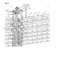
- This embodiment relates to how to attach plant growing boxes to hoisting device and how to hoist their boxes vertically corresponding to growth of their plants.
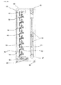
- multistage plant growing boxes (2) are attached to a hoisting device (1) vertically, and each box can be hoisted.
- a hard steel pillar (21) is constituted in the center of the hoisting device, and the hoisting device is fixed on the ground or floor by this pillar.
- the hoisting device (1) is mainly comprised of the steel pillar (21), plates (4) to connect boxes, bolts to fix the plates, a winch (11) to roll up or down the boxes, a wire (9) to connect the uppermost box with the winch (11), a chain sprocket wheel (10) to lead the wire, pulleys (12) (12') and guide-rails (7) to lead the boxes.
- the form of the plant growing box (2) is like a hexagonal pole, and it forms one undersurface, one top surface and four slant faces.
- the height of one box is about 13cm and the width of it is about 2.8m.
- the upper slant surfaces (14)(14') have plant growing pots (3) at regular intervals.
- the box (2) is hollow inside, and nutritious solution is provided and excreted through a pipe (17) connected with a water pipe (16) and a drainage pipe (18). Roots of the vegetation in the pots are soaked in the nutritious solution of boxes and the solution is provided to the vegetation.
- the both ends of plant growing box (2) forms into rectangular solid sliders (8) and these sliders fit into the guide-rails (7), and the boxes slide along the guide-rails (7) vertically.
- the Fig. 17 shows another example of both ends of plant growing boxes (2).
- a couple of guide-ropes (75) that is put up vertically is used instead of guide-rails (7) of Fig. 2 .
- Guide rollers (72) to stabilize the boxes through roller frames (71) are attached to the four corner of the end of the box.
- One side of the roller frames is attached to the boxes and the other side of the roller frames is attached to the guide rollers.
- the forms of the roller frames are optional.
- FIG. 17 three cylindrical rollers (73) are set up in each guide roller (72), and one guide-rope is surrounded by the three cylindrical rollers.
- the plant growing boxes are fixed as the result that the guide rollers of both ends of boxes are connected to the guide ropes.
- the boxes smoothly glide vertically on the basis of their guide-ropes because the guide rollers of boxes rotate corresponding to the rising and falling movement of boxes.
- Snatch blocks (74) form one part of the guide roller.
- the cylindrical snatch blocks rotate like rollers and it can be opened and closed because a guide rope can be inserted to and extracted from the guide roller. This device makes it easy to connect plant growing boxes with guide-ropes.
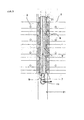
- shafts (19) are attached to the top face (13) and under face (15) at nearly ends of the plant growing boxes.
- the box (2) is connected with plates (4) as the result of inserting the shafts (19) into the holes (22) of plates and fixing them by bolts (5).
- the forms of the shafts are optional, but better form is a cubic that has two planes in order to weld the shafts to both the box (2) and a shock absorber (6).
- the form of the shaft (19) is like cylinder that has two parallel planes, and both ends of the shaft has holes to insert bolts. The ends of the shafts penetrate the holes (22) of the plates and even if the shafts are fixed by bolts, the shaft (19) moves vertically because there are some spaces between the plates and the bolts.
- the shock absorbers (6) prevent each vertical plant growing box (2) or each vertical bolt (5) from colliding each other when the boxes are gone down.
- the shock absorbers are attached to the shafts (19) of undersurface of the boxes.
- the form of the shock absorber is optional, but in this embodiment, the form of it is a rectangular parallelepiped as the same large as the shaft (19).
- the ends of the shock absorber (6) can be inserted to the holes (22) of plates (4), and it supports the vertical movement of the shafts.
- each end of shafts (19) and shock absorbers (6) attached to the undersurface of an upper box (2) is inserted to holes (22) of two plates (4), and the each end of shafts is fixed by bolts (5).
- the other box is located under the upper box and each end of shafts attached to the top surface of the lower box is inserted to the holes (22) of two plates (4), and the each end of the shafts is also fixed by bolts (5). People can easily do this process at the both ends of the box simultaneously.
- the lower box can easily be removed as the result that bolts (5) of both ends of the lower box are took off and the both ends of shafts (19) are pulled out from the holes (22). Namely, the boxes can easily be attached or removed by bolting or unbolting four parts of the ends of the upper box and / or lower box.
- the upper box and lower box can be opened at the width of length of plate's hole (22).
- the movement can be conveyed to the lower box through plates connected their boxes and the lower box also gone up.
- All multistage plant growing boxes are connected each other, and lower boxes are gone up corresponding to the movement that the upper box is gone up.
- the width between vertical boxes is equal because the length of the plates is also equal.
- the upper box is gone down, the lower box is also gone down.
- the shock absorbers (6) of box are attached to the shafts (19) of the lower box, and the movement of box stops.
- the plates (4) of the uppermost plant growing box is connected to wires (9). These wires are extended to the lowest part of the hoisting device through a chain sprocket wheel (10) and pulleys (12, 12') at the top of the hoisting device (1). As Fig.3 shows, the wires are connected to a winch on the ground, and the uppermost box (2) can be moved vertically through the wires by controlling the winch.
- the hoisting device (1) are installed on both sides of multistage boxes, and the boxes are moved in equilibrium.
- FIG.4 A physical relationship between plant growing boxes (2) and artificial light sources (20) are described referring to Fig.4 , Fig.8 , Fig.10 and Fig.11 .
- multistage plant growing boxes that are connected vertically by hoisting devices are located in rows.
- a row of an artificial light source is located between two rows of the boxes.
- Fig.4 shows cross section of side view about them, however, hoisting devices or plates etc. are not illustrated in order to make their location clear.
- rows of artificial light sources (20) are parallel to rows of plant growing boxes.
- the artificial light sources are installed vertically on the ground in order to irradiate from the lowermost box to the uppermost box that is lifted up.
- the height from the lowermost box to the uppermost box that is lifted up is about 11 meter
- the height of an artificial light source (20) is also about 11 meter.
- the artificial light source is composed of multiple stick type fluorescent lamps vertically in this embodiment, and it can compose of spherical type lamps.
- the stick type fluorescent lamps are connected vertically at 1.2 meter intervals and we can turn on and off the light source at 1.2 meter intervals. Furthermore, power consumption of this system decreases effectively because one row of the artificial light source can be irradiated both sides rows of plant growing pots (3) on boxes (2).
- wires (9) that are suspended through chain sprocket wheels (10) are lowered on the ground.
- the point of the wires forms a hook.
- Plates (4) that are connected with an uppermost plant growing box (2) can be suspended by the hook.
- the uppermost plant growing box, which seedlings of vegetation are planted in the plant growing pots (3), is connected with the plates (4).
- the uppermost box is gone up a little by controlling a winch (11).
- An two-stage box, which seedlings of vegetation are also planted in the plant growing pots, is located under the uppermost box, and is connected with the uppermost box vertically by using plates (4).
- Sliders (8) of the both ends of the boxes are fitted to guide-rails (7) of hoisting device, and the boxes can be moved smoothly and vertically. The same process is repeated to the end of the lowermost box. According to this embodiment, the 55 boxes are located vertically.
- the uppermost box is lifted high by the hoisting device (1), and the other boxes are under it at regular intervals that the width of them is equal to the length of holes (22) of plates.
- the intervals between each box are about 7cm and the height between the uppermost box and the lowermost box is about 11 meter (The height of the box is about 13 cm , the width between the each box is about 7 cm and the number of boxes is 55).
- the lowermost box is fixed by stoppers and it cannot be moved.
- the uppermost box is gone up by controlling the hoisting device (1) in order to avoid contact of leaves and make enough space for photosynthesis.
- Each box under the uppermost box is also gone up because they are connected by plates (4).
- all artificial light sources are turned on from the bottom to the top (about 11 meter) and all boxes are irradiated by the light. It can be possible to harvest the vegetation after about 8 days.
- the multistage plant growing boxes (2') that has one slant face on only one side can be installed at the both walls sides in the plant (23). It can be possible that the number of cultivation increases.
- the power of consumption can be saved about 33 % off because the multistage boxes can be gone down and upper side of artificial light sources (about 3.85 meter) can be turned off, when the vegetation is undeveloped. Workers can safely and easily attach and remove the boxes on the ground without a ladder because the box can be attach to and remove from the hoisting device one by one. And workers can operate at minimum movement as the result of moving on the ground, and we need not large air conditioner because the system of this invention is very compact even if the plant is at high densities.
- the second embodiment of this invention relates to the way to grow different size vegetation.
- the system of this embodiment is also the same as one of the first embodiment.
- a change in vegetation's size depends on the kinds of vegetation. Vegetables such as lettuce or spinach become bigger as growing. On the other hand, some flowers don't become bigger as growing. This invention can be applied to cultivation of these two kinds of vegetation.
- the top side of artificial light sources (20) can be turned off and power consumption can be saved.
- the vegetation of the lower half of the boxes grows, the enough spaces for growing are provided by going up the boxes.
- the third embodiment of this invention relates to the way to harvest the vegetation after ripeness.
- the each plant growing box is located on high position after the vegetation in the pots (3) grows. Firstly, the lowermost box (2) can be removed from the upper box by removing it from plates (4). Secondly, each boxes is gone down by controlling the hoisting device (1). And the lowermost box can be removed from the upper box. This process is repeated. It is also possible to remove the boxes two by two. And it is possible to operate this process smoothly by dividing the workers into two teams, namely, one is the team to control the hoisting device (1) and the other is the team to remove the boxes and harvest the plants.
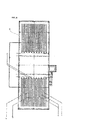
- the forth embodiment of this invention relates to a household energy-saving device for growing plant that the energy-saving system for vertically moving plant growing box is included in the desired housing.
- the household energy-saving device for growing plant (31) is mainly composed of multistage plant growing boxes (33) that are formed vertically, a hoisting device (38) that control the vertical movement of boxes, and artificial light sources (50) that irradiation range can be controlled.
- These instruments are in a rectangular parallelepiped housing (32).
- the width of the housing is about 120 cm, the height of it is about 170 cm and the depth of it is about 60 cm.
- the underside of the housing has casters, and the housing is movable freely.
- the housing (32) has one door and we can open and shut the door.
- An acrylic glazing (56) is fitted to the door and we can see the inside situation of the box without opening the door.
- the inside of the box is divided into two sections by a wall (55).
- the front side of the section is the space to plant vegetation by plant growing boxes, and the back side of the section is the space to install a hoisting device (38) to move the boxes vertically.
- the hoisting device is mainly composed of wires (35) that connect each multistage plant growing boxes, wires (41) that connect the uppermost box with a roller (40) to hoist the box, a roller that can be wound the wires (41) and a handle (39) to rolling the roller.
- Fig. 13 shows, the upper side of the back side section has the cylindrical roller (40), and the length of it is nearly equal to the width of the housing. An one end of the roller sticks out into the outside the housing, and the roller can be rolling by turning the handle (39) because the handle is installed the end of the roller.
- the wires (41) are wound around the both near ends of the roller (40), and supporting members (36) to place the uppermost box are attached to the wires.
- the supporting members can be gone up or gone down by rotating the roller because wires are wound or rewound.
- the lower plant growing boxes are connected with the wires (35).
- the material of the wires is optional as long as nonelastic and flexibility wires (e.g. rubber tube etc.).
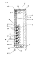
- Fig. 15 shows, all supporting members can be gone up by winding the wires (41) because the uppermost supporting member can be gone up and the lower supporting members can also be gone up as the result of connecting them by wires.
- the multistage plant growing boxes are placed on the supporting members and desired space can be made between each box.
- all supporting members can be gone down by rewinding the wires (41), and the upper supporting members come in contact with the top face (53) of the lower supporting members and stop the motion.
- the lowermost supporting member comes in contact with the top face of a tank (42) and stops the motion.
- the each plant growing box can be piled up. We can change the width between the uppermost box and the lowermost box freely by controlling the handle (39).
- a stopper fixes the handle and prevents it from moving unintentionally by weight of the boxes etc.
- the Fig. 14 shows the state of wire bending easily to understand, but actually, the wire can be bent inside the section of hoisting device.
- the plant growing boxes are cubic forms that are made of six faces, namely, top face (53) and under face (54) parallel to the floor, two slant faces (51, 52) on the door and two side faces.
- the inside of the boxes is hollow, and nutritious solution is provided into the spaces.
- the slant face (51) of each box has some circular pots (34). Vegetation is planted into the pots and the roots of the vegetation can be submerged under the nutritious solution through the pots.
- the angle of the slant face (51) is very important and the desirable degree of the angle is 40-70 to a horizontal plane, because we must expand the spaces between boxes to prevent their contact and reduce the number of boxes under the angle of 40 degrees, and we must pay attention to fall of vegetation from the pots over the angle of 70 degrees.
- the nutritious solution of the tank (42) can be moved to an upper tank (43) by a suction pump (44) through a water pipe (45). And the nutritious solution can be moved to each multistage plant growing boxes through a elastic water pipe (46), and finally, it can be moved to the tank (42).
- This circulation of the solution can desirably be controlled automatically.
- Fig. 13-15 show, the both ends of under face (54) and slant face (52) of each plant growing box are (33) supported by each the supporting member (36) which sectional view is like "L" character, and the each box does not fall.
- the near both ends of the wall (55) have guide-rails (37), or cut lines vertically, and the supporting members (36) are protruding from the section of hoisting device (38) to the section of plant growing boxes through the guide-rails.
- the width between the supporting members is nearly equal to the width between the guide-rails, and the supporting members can be moved vertically along to the guide-rails.
- the end of the supporting member in the hoisting device section forms large a rectangular parallelepiped (or spherical type that has two flat surfaces at least), and one flat surface contacts to the wall (55) and another flat face contacts to the back face of the box(32). So, the supporting members are fixed. It can be possible to connect a right supporting member and a left supporting member by rods in order to keep their balance. And it can be possible to thicken the wall (55) and to form slot only parts of the guide-rails(37).
- the plant growing boxes can be desirably to attach to and remove from the supporting members though the boxes can be possibly fixed to the members.
- artificial light sources are installed inside of the door.
- the form of them is optional, and in this embodiment, stick type lamps are installed in parallel with floor line.
- the irradiation range of the light sources can be changeable corresponding to the height of the plant growing boxes, it can be possible to install the light sources longitudinally.
- Fine EEFL lamps are applied to the light sources.
- the EEFL lamp has a diameter of about 5 mm.
- Two acrylic boards (56) are fitted to the door, and the EEFL lamps are fitted between the boards. Humans cannot touch the lamps, and it prevents the lamps from being damaged in opening and closing motion.
- the artificial light sources can be switched to three types, namely, (1) all light sources can be turned off, (2) all light sources can be turned on, (3) in case that each box is gone down, the light sources from the lowermost plant growing box to the uppermost box can be turned on.
- 18 lamps are used and they can be switched to three types, namely, (1) all 18 lamps can be turned off, (2) all 18 lamps can be turned on, (3) only lower 12 lamps can be turned on. It is possible to be switched to more than three types.
- the upper side of the door has a ventilator (49) in order to exhaust heat from light sources, and under side of the door has an admission port (47) in order to inspire cool air from outside.
- the ventilator and admission port are cylinder forms and the ventilator is installed from inside of the door to the upper side of the housing, and the admission port is installed from lower side of the door to inside of the housing.
- the heated air from light sources can be exhausted through the ventilator and cool air can be inspired through the admission port.
- the inside of the box can not be heated by light sources and it can be possible to keep the most suitable temperature to the vegetation in housing.
- the multistage plant growing boxes (33) can be gone down as Fig. 14 shows. Seedlings of vegetation are planted to each pots (34). After the door is closed, the artificial light sources are turned on corresponding to the height from the lowermost box to the uppermost box. In this embodiment, lower 12 light sources are turned on. The light is irradiated to the plant for about 10 days.
- the household energy-saving device for growing plant (31) of this 4th embodiment It is possible for us to cultivate vegetation or greens easily in a house or restaurant by using the household energy-saving device for growing plant (31) of this 4th embodiment. Users do not need particular works because nutritious solution is automatically circulated and light sources are always irradiated. In case of cultivation by artificial light sources, power consumption and power rate normally increases. Using the household energy-saving device for growing plant, however, the power consumption and power rate decreases because we can control the height from the lowermost box to the uppermost box and we can also control the range of irradiation corresponding to the height. Though the power consumption depends on the height of one box or numbers of boxes, we can reduce about one-third power consumption as the result of moving the boxes. We can cultivate plants efficiently because we do not need to decrease the number of plants. We can also keep ample spaces for cultivation because we can move each multistage box to keep the spaces for plants.
- a household device for growing plant 60
- the present invention is not limited to the above embodiments, and it is possible to design the device freely according the subject matter of the invention.
Landscapes
- Life Sciences & Earth Sciences (AREA)
- Environmental Sciences (AREA)
- Cultivation Receptacles Or Flower-Pots, Or Pots For Seedlings (AREA)
- Hydroponics (AREA)
- Cultivation Of Plants (AREA)
Applications Claiming Priority (1)
| Application Number | Priority Date | Filing Date | Title |
|---|---|---|---|
| PCT/JP2009/068029 WO2011048657A1 (ja) | 2009-10-19 | 2009-10-19 | 植物育成ボックス昇降省エネシステム、植物育成ボックス昇降省エネ方法及び家庭用植物育成省エネ装置 |
Publications (2)
| Publication Number | Publication Date |
|---|---|
| EP2491784A1 true EP2491784A1 (de) | 2012-08-29 |
| EP2491784A4 EP2491784A4 (de) | 2013-12-25 |
Family
ID=43899910
Family Applications (1)
| Application Number | Title | Priority Date | Filing Date |
|---|---|---|---|
| EP09850555.5A Withdrawn EP2491784A4 (de) | 2009-10-19 | 2009-10-19 | Energiesparsystem zur vertikalen bewegung eines pflanzenzüchtungskastens, energiesparverfahren zur vertikalen bewegung eines pflanzenzüchtungskastens und energiesparendes haushaltsgerät für pflanzenzüchtung |
Country Status (3)
| Country | Link |
|---|---|
| EP (1) | EP2491784A4 (de) |
| JP (1) | JP5639072B2 (de) |
| WO (2) | WO2011048657A1 (de) |
Cited By (8)
| Publication number | Priority date | Publication date | Assignee | Title |
|---|---|---|---|---|
| GB2494997A (en) * | 2011-09-22 | 2013-03-27 | Haygrove Ltd | Apparatus and method for growing crops on suspended carriers |
| WO2014158038A1 (en) * | 2013-03-25 | 2014-10-02 | Garbarek Paweł | Set for creating walls with decorative plants |
| GB2539397A (en) * | 2015-06-12 | 2016-12-21 | Nat College Of Art And Design | Micro Farm |
| US10098287B2 (en) | 2014-06-06 | 2018-10-16 | RackREIT, LLC | System and method for cultivating plants |
| US10306847B2 (en) | 2016-07-14 | 2019-06-04 | Mjnn, Llc | Environmentally controlled vertical farming system |
| EP3750398A1 (de) * | 2017-05-30 | 2020-12-16 | Fraunhofer-Gesellschaft zur Förderung der angewandten Forschung e.V. | Vorrichtung zur förderung des wachstums von pflanzen |
| WO2022064200A1 (en) * | 2020-09-23 | 2022-03-31 | Vertical Future Limited | Crop production system and method |
| US12284954B2 (en) | 2017-05-30 | 2025-04-29 | Fraunhofer-Gesellschaft Zur Foerderung Der Angewandten Forschung E.V. | Device for promoting the growth of plants |
Families Citing this family (13)
| Publication number | Priority date | Publication date | Assignee | Title |
|---|---|---|---|---|
| CN102150607B (zh) * | 2011-04-21 | 2012-10-03 | 北京林业大学 | 一种林木切枝水培装置 |
| CN102668964B (zh) * | 2012-05-21 | 2014-06-04 | 北京航空航天大学 | 一种植物工厂 |
| CN103510729A (zh) * | 2012-06-25 | 2014-01-15 | 汪建军 | 一种多层种植养殖并可创造环保能源的框架楼 |
| WO2015139087A1 (en) * | 2014-03-18 | 2015-09-24 | Bax Heath William | Downpipe assembly |
| CA3051097A1 (en) * | 2017-01-20 | 2018-07-26 | Greenphyto Pte. Ltd. | Farming management system |
| CN109781938B (zh) * | 2018-12-03 | 2023-04-14 | 中国辐射防护研究院 | 一种模拟放射性核素降雪途径沉降的装置 |
| KR102220778B1 (ko) * | 2020-07-10 | 2021-03-02 | 조장희 | 에너지 절약 및 작물 발육 보조를 위한 수경재배용 설비 시스템 |
| CN112470912B (zh) * | 2020-12-09 | 2025-04-04 | 东北师范大学 | 一种用于城市上空多层绿化的装置及方法 |
| US11457581B1 (en) * | 2020-12-15 | 2022-10-04 | Di Marco Millard | Hydroponic growing system |
| CN114557213A (zh) * | 2022-03-21 | 2022-05-31 | 百色学院 | 一种植物生态学多层植物栽培对照设备 |
| WO2023236130A1 (zh) * | 2022-06-09 | 2023-12-14 | 张轩恺 | 货柜或密闭空间内的垂直式水耕植栽系统 |
| KR102553360B1 (ko) | 2022-07-27 | 2023-07-06 | 송요순 | 상하로 이동 가능한 다단 베드 작물 재배 시스템 |
| WO2026020410A1 (zh) * | 2024-07-25 | 2026-01-29 | 张轩恺 | 货柜或密闭空间内的垂直蓄水式水耕植栽系统 |
Family Cites Families (10)
| Publication number | Priority date | Publication date | Assignee | Title |
|---|---|---|---|---|
| JP2759172B2 (ja) * | 1989-04-18 | 1998-05-28 | 藤田 光夫 | 植物栽培設備 |
| DK174990A (da) * | 1990-07-23 | 1992-01-24 | Poul Kristensen | Fremgangsmaade samt anlaeg til opformering af planter |
| JPH0661038A (ja) * | 1991-10-23 | 1994-03-04 | Yokogawa Medical Syst Ltd | 磁界発生装置および磁材および磁界発生方法 |
| JPH0661038U (ja) * | 1993-02-15 | 1994-08-30 | 株式会社タイショー | 発芽・育苗装置 |
| JPH07111828A (ja) * | 1993-10-21 | 1995-05-02 | Supeesu Atsupu:Kk | 植物の立体栽培装置 |
| JPH0923772A (ja) * | 1995-07-13 | 1997-01-28 | Sekisui Plastics Co Ltd | 栽培用ベッドの昇降装置 |
| JPH11127687A (ja) * | 1997-10-29 | 1999-05-18 | Zipangu Housing:Kk | 植物の多段栽培方法と装置及び採光方法と装置並びに植物栽培システム |
| EP1210868A1 (de) | 1999-01-27 | 2002-06-05 | Seiichi Marumoto | Senkrechtes hydroponisches sprühsystem mit ultrahochdichtungsanlage und zuchtplatte |
| JP2003269113A (ja) * | 2002-03-15 | 2003-09-25 | Toshiba Corp | 複合エネルギーシステム |
| US7617057B2 (en) * | 2005-12-21 | 2009-11-10 | Inst Technology Development | Expert system for controlling plant growth in a contained environment |
-
2009
- 2009-10-19 JP JP2011537040A patent/JP5639072B2/ja not_active Expired - Fee Related
- 2009-10-19 EP EP09850555.5A patent/EP2491784A4/de not_active Withdrawn
- 2009-10-19 WO PCT/JP2009/068029 patent/WO2011048657A1/ja not_active Ceased
-
2010
- 2010-10-19 WO PCT/JP2010/068381 patent/WO2011049084A1/ja not_active Ceased
Cited By (13)
| Publication number | Priority date | Publication date | Assignee | Title |
|---|---|---|---|---|
| GB2494997B (en) * | 2011-09-22 | 2016-08-03 | Haygrove Ltd | Improved substrate growing system |
| GB2494997A (en) * | 2011-09-22 | 2013-03-27 | Haygrove Ltd | Apparatus and method for growing crops on suspended carriers |
| WO2014158038A1 (en) * | 2013-03-25 | 2014-10-02 | Garbarek Paweł | Set for creating walls with decorative plants |
| US11178824B2 (en) | 2014-06-06 | 2021-11-23 | RackREIT, LLC | System and method for cultivating plants |
| US10098287B2 (en) | 2014-06-06 | 2018-10-16 | RackREIT, LLC | System and method for cultivating plants |
| GB2539397A (en) * | 2015-06-12 | 2016-12-21 | Nat College Of Art And Design | Micro Farm |
| GB2539397B (en) * | 2015-06-12 | 2021-07-14 | Nat College Of Art And Design | Micro Farm |
| US10973185B2 (en) | 2016-07-14 | 2021-04-13 | Mjnn Llc | Control and sensor systems for an environmentally controlled vertical farming system |
| US10306847B2 (en) | 2016-07-14 | 2019-06-04 | Mjnn, Llc | Environmentally controlled vertical farming system |
| EP3750398A1 (de) * | 2017-05-30 | 2020-12-16 | Fraunhofer-Gesellschaft zur Förderung der angewandten Forschung e.V. | Vorrichtung zur förderung des wachstums von pflanzen |
| US12201071B2 (en) | 2017-05-30 | 2025-01-21 | Fraunhofer-Gesellschaft Zur Foerderung Der Angewandten Forschung E.V. | Device for promoting the growth of plants |
| US12284954B2 (en) | 2017-05-30 | 2025-04-29 | Fraunhofer-Gesellschaft Zur Foerderung Der Angewandten Forschung E.V. | Device for promoting the growth of plants |
| WO2022064200A1 (en) * | 2020-09-23 | 2022-03-31 | Vertical Future Limited | Crop production system and method |
Also Published As
| Publication number | Publication date |
|---|---|
| WO2011048657A1 (ja) | 2011-04-28 |
| JPWO2011048657A1 (ja) | 2013-03-07 |
| WO2011049084A1 (ja) | 2011-04-28 |
| JP5639072B2 (ja) | 2014-12-10 |
| EP2491784A4 (de) | 2013-12-25 |
Similar Documents
| Publication | Publication Date | Title |
|---|---|---|
| EP2491784A1 (de) | Energiesparsystem zur vertikalen bewegung eines pflanzenzüchtungskastens, energiesparverfahren zur vertikalen bewegung eines pflanzenzüchtungskastens und energiesparendes haushaltsgerät für pflanzenzüchtung | |
| US10736283B2 (en) | Rotatable rack system | |
| US4813176A (en) | Aeroponic apparatus | |
| EP3478050B1 (de) | System und verfahren für hydroponisches pflanzenwachstum | |
| US5943818A (en) | System for propagation of plants | |
| KR20120094769A (ko) | 식물재배시스템 | |
| CN104798622B (zh) | 一种植物工厂系统 | |
| US20180228103A1 (en) | Cultivation device | |
| CN111990136B (zh) | 可升降的梨苗智能培养架 | |
| CN203027814U (zh) | 多功能全自动立体式育苗设备 | |
| JP2928758B2 (ja) | 植物栽培装置 | |
| JP6367552B2 (ja) | 植物栽培装置 | |
| CN207011426U (zh) | 一种水生植物培养箱 | |
| EP4319543A1 (de) | Vorrichtung zur instandhaltung einer pflanze | |
| US12457944B2 (en) | Transformable greenhouse system | |
| CN215602220U (zh) | 轮套种养棚舍 | |
| JP2010088344A (ja) | 移動栽培システムの抜取装置 | |
| CN112825704A (zh) | 一种草莓基质育苗穴盘 | |
| JP2004275178A (ja) | 植物栽培装置 | |
| CN204968669U (zh) | 一种植物工厂系统 | |
| KR101860305B1 (ko) | 하우스용 대량재배형 양액재배시설장치 | |
| CN220157273U (zh) | 一种水培植物养殖设备 | |
| CN221128083U (zh) | 一种智慧农业用吊挂式栽培装置 | |
| CN201563463U (zh) | 一种室内外垂帘绿化可升降的固液二用植生盒 | |
| KR102732681B1 (ko) | 분무 수경 재배 장치 |
Legal Events
| Date | Code | Title | Description |
|---|---|---|---|
| PUAI | Public reference made under article 153(3) epc to a published international application that has entered the european phase |
Free format text: ORIGINAL CODE: 0009012 |
|
| 17P | Request for examination filed |
Effective date: 20120515 |
|
| AK | Designated contracting states |
Kind code of ref document: A1 Designated state(s): AT BE BG CH CY CZ DE DK EE ES FI FR GB GR HR HU IE IS IT LI LT LU LV MC MK MT NL NO PL PT RO SE SI SK SM TR |
|
| DAX | Request for extension of the european patent (deleted) | ||
| A4 | Supplementary search report drawn up and despatched |
Effective date: 20131126 |
|
| RIC1 | Information provided on ipc code assigned before grant |
Ipc: A01G 9/00 20060101ALI20131120BHEP Ipc: A01G 31/06 20060101AFI20131120BHEP |
|
| STAA | Information on the status of an ep patent application or granted ep patent |
Free format text: STATUS: THE APPLICATION IS DEEMED TO BE WITHDRAWN |
|
| 18D | Application deemed to be withdrawn |
Effective date: 20140501 |