EP2490939B1 - Steuervorrichtung für eine kabine eines luft- oder raumfahrzeuges, kabinenmanagementsystem und verfahren zum steuern einer kabine eines luft- oder raumfahrzeuges - Google Patents
Steuervorrichtung für eine kabine eines luft- oder raumfahrzeuges, kabinenmanagementsystem und verfahren zum steuern einer kabine eines luft- oder raumfahrzeuges Download PDFInfo
- Publication number
- EP2490939B1 EP2490939B1 EP10768736.0A EP10768736A EP2490939B1 EP 2490939 B1 EP2490939 B1 EP 2490939B1 EP 10768736 A EP10768736 A EP 10768736A EP 2490939 B1 EP2490939 B1 EP 2490939B1
- Authority
- EP
- European Patent Office
- Prior art keywords
- control signal
- control
- control means
- camera
- cabin
- Prior art date
- Legal status (The legal status is an assumption and is not a legal conclusion. Google has not performed a legal analysis and makes no representation as to the accuracy of the status listed.)
- Not-in-force
Links
- 238000000034 method Methods 0.000 title claims description 12
- 230000001360 synchronised effect Effects 0.000 claims description 5
- 238000005286 illumination Methods 0.000 description 35
- 238000005070 sampling Methods 0.000 description 12
- 238000010586 diagram Methods 0.000 description 6
- 238000012544 monitoring process Methods 0.000 description 5
- 230000004044 response Effects 0.000 description 5
- 230000004913 activation Effects 0.000 description 2
- 230000008901 benefit Effects 0.000 description 2
- 230000000694 effects Effects 0.000 description 2
- 230000001795 light effect Effects 0.000 description 2
- 230000003213 activating effect Effects 0.000 description 1
- 238000004364 calculation method Methods 0.000 description 1
- 238000004590 computer program Methods 0.000 description 1
- 230000001419 dependent effect Effects 0.000 description 1
Images


Classifications
-
- H—ELECTRICITY
- H04—ELECTRIC COMMUNICATION TECHNIQUE
- H04N—PICTORIAL COMMUNICATION, e.g. TELEVISION
- H04N7/00—Television systems
- H04N7/18—Closed-circuit television [CCTV] systems, i.e. systems in which the video signal is not broadcast
- H04N7/181—Closed-circuit television [CCTV] systems, i.e. systems in which the video signal is not broadcast for receiving images from a plurality of remote sources
-
- B—PERFORMING OPERATIONS; TRANSPORTING
- B64—AIRCRAFT; AVIATION; COSMONAUTICS
- B64D—EQUIPMENT FOR FITTING IN OR TO AIRCRAFT; FLIGHT SUITS; PARACHUTES; ARRANGEMENT OR MOUNTING OF POWER PLANTS OR PROPULSION TRANSMISSIONS IN AIRCRAFT
- B64D45/00—Aircraft indicators or protectors not otherwise provided for
- B64D45/0015—Devices specially adapted for the protection against criminal attack, e.g. anti-hijacking systems
- B64D45/0051—Devices specially adapted for the protection against criminal attack, e.g. anti-hijacking systems by monitoring passengers or crew on aircraft
- B64D45/0053—Devices specially adapted for the protection against criminal attack, e.g. anti-hijacking systems by monitoring passengers or crew on aircraft using visual equipment, e.g. cameras
-
- B—PERFORMING OPERATIONS; TRANSPORTING
- B64—AIRCRAFT; AVIATION; COSMONAUTICS
- B64D—EQUIPMENT FOR FITTING IN OR TO AIRCRAFT; FLIGHT SUITS; PARACHUTES; ARRANGEMENT OR MOUNTING OF POWER PLANTS OR PROPULSION TRANSMISSIONS IN AIRCRAFT
- B64D47/00—Equipment not otherwise provided for
- B64D47/02—Arrangements or adaptations of signal or lighting devices
-
- B—PERFORMING OPERATIONS; TRANSPORTING
- B64—AIRCRAFT; AVIATION; COSMONAUTICS
- B64D—EQUIPMENT FOR FITTING IN OR TO AIRCRAFT; FLIGHT SUITS; PARACHUTES; ARRANGEMENT OR MOUNTING OF POWER PLANTS OR PROPULSION TRANSMISSIONS IN AIRCRAFT
- B64D11/00—Passenger or crew accommodation; Flight-deck installations not otherwise provided for
- B64D2011/0038—Illumination systems for cabins as a whole
-
- B—PERFORMING OPERATIONS; TRANSPORTING
- B64—AIRCRAFT; AVIATION; COSMONAUTICS
- B64D—EQUIPMENT FOR FITTING IN OR TO AIRCRAFT; FLIGHT SUITS; PARACHUTES; ARRANGEMENT OR MOUNTING OF POWER PLANTS OR PROPULSION TRANSMISSIONS IN AIRCRAFT
- B64D2203/00—Aircraft or airfield lights using LEDs
Definitions
- the present invention relates to a control device for a cabin of an aircraft or spacecraft, to a cabin management system and to a method for controlling a cabin of an aircraft or spacecraft.
- a conventional aircraft cabin there are a plurality of cameras and lighting devices, such as light emitting diodes or fluorescent tubes.
- the cameras are associated, for example, with a Cabin Video Monitoring System (CVMS) or a Cockpit Door Surveillance System (CDSS), which has the function of monitoring the cabin and the area of the cockpit door by means of the cameras.
- CVMS Cabin Video Monitoring System
- CDSS Cockpit Door Surveillance System
- the video data stream captured by the cameras is provided to the flight attendants on a Flight Attendance Panel (FAP).
- FAP Flight Attendance Panel
- the recorded video stream can also be displayed on a cockpit display.
- interference such as interference or aliasing
- the video data streams sampled by the cameras include these disturbances due to the pulse width modulation of the aircraft cabin lighting equipment.
- control of the CDSS and CVMS was first integrated into the Cabin Intercommunication Data System (CIDS). Furthermore, the CIDS also hosts the control of the lighting of the aircraft cabin.
- CIDS Cabin Intercommunication Data System
- the publication DE 40 11 842 A1 discloses an illumination device for objects picked up by a camera with a CCD imager.
- the illumination device is controlled by a control unit in the pulse mode, by which a stroboscopic effect is achieved.
- the illumination device comprises a light source having a near infrared light emitting diode array whose diodes are selectively applied by the control unit with at least one variable width pulse during each frame period.
- the publication EP 2 107 419 A1 discloses a lighting device in which the pulse rate of an LED illumination is adjusted to the variable sampling rate of a camera.
- a control device for a cabin of an aircraft or spacecraft having a first control means which is set up to provide at least a first control signal for actuating at least one camera of the car for setting a sampling rate of the at least one camera, and a second control means, which is set up to provide at least one second control signal for activating at least one illumination device of the car for setting a pulse width modulation of the at least one illumination device, wherein the first control means is adapted to provide the first control signal in response to the at least one second control signal such that the sampling rate of the at least one camera and the pulse width modulation of the at least one illumination device are synchronized.
- a cabin management system for an aerospace vehicle which has a control device as explained above, which can be coupled to a plurality of cameras by means of a first bus and with a plurality of lighting devices by means of a second bus.
- One advantage of the present invention is that the first control signal for controlling the cameras is generated as a function of the second control signal for driving the illumination device. As a result of this dependence, the activation of the illumination device can avoid potentially harmful interference during recording or scanning by the camera or the cameras.
- the first control means provides the first control signal as a function of second control signal provides such that a potentially caused by the activation of the illumination device disturbance is avoided when recording the camera.
- the first control means and the second control means provide the first control signal and the second control signal such that the sampling rate is formed as a non-multiple of the frequency of the pulse width modulation.
- the second control means forms the second control signal with a first signal component and a second signal component.
- the first signal component is suitable for setting a frequency of the pulse width modulation for setting a light quantity of the light emitted by the at least one illumination device.
- the second signal component is suitable for setting a color vector for setting a color of the light emitted by the at least one illumination device for the at least one illumination device.
- the respective camera has at least one filter means for compensating a non-linear color characteristic of the camera.
- the second control means is adapted to control the respective filter means of the respective camera by means of the second signal component of the second control signal.
- This second signal component comprises a color compensation vector.
- the light of the illumination devices in particular the light of LEDs, can also be used for colored light effects, so-called soft light effects.
- the colored illuminated booth has, as stated above, also effects on the recording quality of the cameras or video cameras due to the non-linear color characteristics of the cameras.
- filters in particular electronic filters, such a non-linear color characteristic can be advantageously compensated.
- This color compensation is performed automatically in particular by a reference signal, the third control signal.
- This third control signal is thus advantageously suitable for controlling the generation of the first and second control signals.
- the second control means forms the second control signal with the first signal component, the second signal component and a third signal component.
- the third signal component is suitable for switching between a black-and-white mode and a color mode of the respective camera.
- the cameras can be automatically switched to black and white mode. If the dark environment becomes brighter due to illumination of the illumination device, it is also possible to switch back automatically to the color mode by means of the third signal component.
- a third means is provided, which is set up to divide the cabin into different lighting zones, each having at least one lighting device, and to control the first control means and the second control means by means of a third control signal.
- the third means is preferably designed as a cabin assignment module (CAM).
- the third control means is coupled to a look-up table for providing the third control signal, which stores associations of the first control signal to the second control signal and to the respective illumination device or to the respective illumination zone.
- the first control means and the second control means provide a respective first control signal and a respective second control signal in response to the third control signal for the corresponding illumination zone.
- the respective illumination device has a plurality of color-specific light-emitting diodes in each case.
- the respective camera has a plurality of respective color-specific sensors.
- the first control means and the second control means form the first control signal and the second control signal in such a way that switching on a respective color-specific light-emitting diode triggers a switching on of the corresponding color-specific sensor. For example, this allows the exposure time of the cameras to be controlled individually, eg for red-specific sensors, a longer switch-on time can be set than for blue-specific sensors.
- the respective means, the first to third control means can be implemented in terms of hardware or software.
- the respective means as a device, for example as a computer or microprocessor, device or as part of a Systems, for example as a computer system, be trained.
- the respective means may be designed as a computer program product, as a function, as a routine, as part of a program code or as an executable object.
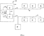
- FIG. 1 a schematic block diagram of a first embodiment of a control device 10 according to the invention is shown.
- the device 10 has a first control means 11 for driving at least one camera 21-23.
- the control device 10 is coupled to the cameras 21-23 by means of a first bus 50.
- the first control signal S1 is transmitted by the control device 10, in particular the first control means 11, via the bus 50 to the cameras 21-23.
- the first control means 11 is adapted to provide the first control signal S1 in response to at least one second control signal S2 for driving at least one lighting device 31-33 of the cabin or to generate.
- the first control signal S1 is generated in such a way that a disturbance potentially caused by the actuation of the illumination device 31-33 or illumination devices is avoided during a recording by the respective camera 21-23.
- Fig. 2 shows a schematic block diagram of a second embodiment of a control device according to the invention 10.
- the control device 10 according to the invention Fig. 2 comprises a first control means 11, a second control means 12 and a third control means 13.
- the control device 10 is designed, for example, as a CIDS director.
- the first control means 11 is designed for example as a video controller.
- the second control means 12 is, for example, a cabin illumination application.
- the third control means 13 is preferably a cabin assignment module.
- the control device 40 according to the invention may be part of the cabin management system (CIDS).
- CIDS cabin management system
- the second embodiment according to Fig. 2 has all the features of the first embodiment Fig. 1 which are not explained again to avoid repetition.
- the second control means 12 is suitable for driving the lighting devices 31-33 in the cabin.
- To the second control means 12 is coupled by means of a second bus 60 to the lighting devices 31-33.
- the respective illumination device 31-33 can be designed as an LED, an arrangement of a plurality of LEDs or as a fluorescent tube. In the embodiment as an arrangement of a plurality of LEDs, the LEDs can also be embodied as differently colored LEDs.
- the first control means 11 and the second control means 12 are adapted to provide the first control signal S1 for adjusting the sampling rate of the cameras 21-23 and the second control signal for adjusting the pulse width modulation of the lighting devices 31-33 such that the sampling rate and the pulse width modulation are synchronized are.
- the sampling rate is a non-multiple of the frequency of the pulse width modulation.
- the second control means 12 forms the second control signal S2 with a first signal component and a second signal component.
- the first signal component is suitable for setting a frequency of the pulse width modulation for setting a light quantity, in particular the brightness, of the light emitted by the illumination devices 31-33.
- the second signal component is particularly suitable for setting a color vector for adjusting the color of the light emitted by the illumination devices 31-33.
- the respective camera 21-23 can have a filter means, in particular an electronic filter, for compensation of a non-linear color characteristic.
- the second control means 12 is preferably adapted to control the respective filter means by means of the second signal component of the second control signal S2.
- the second signal component preferably comprises a color compensation vector for compensating the above-mentioned non-linear color characteristic.
- the second control means 12 form the second control signal S2 with a further signal component.
- the further signal component is particularly suitable for switching between a black-and-white mode and a color mode of the respective camera 21-23.
- the third control means 13 the cabin assignment module, is set up to divide the car into different lighting zones, each with a plurality of lighting devices 21-23.
- the third control means 13 controls the first control means 11 and the second control means 12 by means of a third control signal S3.
- the third control means 13 is preferably coupled to a look-up table 14 for providing this third control signal S3.
- the look-up table 14 may also be part of the third control means 13, as in FIG Fig. 2 shown.
- the look-up table 14 stores assignments of the first control signal S1 to the second control signal S2 and to the respective illumination device 31-33 or to the respective illumination zone.
- a suitable pair of first and second control signals S1 and S2 can be provided for the respective illumination device 31-33 or for the respective illumination zones.
- the first control means 11 and the second control means 12 provide a respective first control signal S1 and a respective second control signal S2 and transmit them via the buses 50 and 60.
- control signals S2 and S3 are provided for the first control means 11, which generates the first control signal S1 in dependence thereon.
- the cabin video monitoring application (Cabin Video Monitoring Application) as the first control means 11 of the control device 10 as a CIDS director calculates the sampling rate Color compensation vector and the black and white mode switching signal for the cameras 21-23. The latter three form the first control signal S1.
- the calculation of this first control signal S1 can be calculated individually for the respective cameras in each lighting zone.
- the assignments, which cameras are arranged in which lighting or car zone, are stored in the third control means 13, the cabin assignment module.
- the car video surveillance application sends this first control signal S1 to the cameras 21-23 via the first bus 50, in particular a cabin video network.
- the cameras 21-23 receive the first control signal S1 and set their sampling rate, the color compensation filter, and the black-and-white mode accordingly, respectively.
- the cameras 21-23 then record the video data frames at the defined sampling rate, perform data processing with the defined filter, and then set the black and white mode accordingly. Finally, this video data stream is provided for monitoring by the flight attendant terminal 70 and a potential cockpit display.
- FIG. 3 a schematic flow diagram of an embodiment of the inventive method for controlling at least one camera 21-23 shown for a cabin of an aircraft or spacecraft.
- the embodiment of the method according to Fig. 3 has the method steps 301 and 302:
- a first control signal S1 for the at least one camera 21-23 is dependent on at least one second Control signal S2 provided.
- the second control signal S2 is suitable for driving at least one illumination device 31-33 of the cabin.
- the at least one camera 21-23 is controlled by means of the provided at least one first control signal S1.
Landscapes
- Engineering & Computer Science (AREA)
- Aviation & Aerospace Engineering (AREA)
- Multimedia (AREA)
- Signal Processing (AREA)
- Studio Devices (AREA)
- Circuit Arrangement For Electric Light Sources In General (AREA)
- Traffic Control Systems (AREA)
Description
- Die vorliegende Erfindung bezieht sich auf eine Steuervorrichtung für eine Kabine eines Luft- oder Raumfahrzeuges, auf ein Kabinenmanagementsystem und auf ein Verfahren zum Steuern einer Kabine eines Luft- oder Raumfahrzeuges.
- Obwohl auf beliebige Luft- oder Raumfahrzeuge anwendbar, werden die vorliegende Erfindung sowie die ihr zugrundeliegende Problematik in Bezug auf Passagierflugzeuge näher erläutert.
- In einer herkömmlichen Flugzeugkabine existieren eine Mehrzahl von Kameras und Beleuchtungseinrichtungen, wie Leuchtdioden oder Leuchtstoffröhren. Die Kameras sind beispielsweise einem Kabinenüberwachungssystem (Cabin Video Monitoring System; CVMS) oder einem Cockpittür-Kontrollsystem (Cockpit Door Surveillance System; CDSS) zugeordnet, welche die Funktion erfüllen, die Kabine und den Bereich der Cockpittüre mittels der Kameras zu überwachen. Der durch die Kameras aufgenommene Video-Datenstrom wird den Flugbegleitern auf einem Flugbegleiterendgerät (Flight Attendance Panel; FAP) bereitgestellt. Des Weiteren kann der aufgenommene Videodatenstrom auch auf einem Cockpit-Display dargestellt werden.
- Die Anmelderin hat festgestellt, dass Störungen, wie Interferenzen oder Alias-Effekte, bei dem aufgenommenen Videostrom vorkommen.
- Die durch die Kameras abgetasteten Video-Datenströme beinhalten diese Störungen aufgrund der Pulsweitenmodulation der Beleuchtungseinrichtungen der Flugzeugkabine.
- In der A 350 wurde die Steuerung des CDSS und des CVMS erstmals in das Kabinen-Managementsystem, das so genannten Cabin Intercommunication Data System (CIDS), integriert. Des Weiteren hostet das CIDS auch die Steuerung der Beleuchtung der Flugzeugkabine.
- In der A 380 sind die Steuerung der CVMS/CDSS und der Kabinenbeleuchtung getrennte Systeme, so dass eine durch eine Ansteuerung der Beleuchtungseinrichtung verursachte Störung, wie beispielsweise Interferenz oder Alias-Effekte, bei einer Aufnahme der jeweiligen Kamera nicht vermieden werden können. Die Druckschrift
DE 40 11 842 A1 offenbart eine Beleuchtungseinrichtung für Objekte, die von einer Kamera mit einem CCD-Bildaufnehmer aufgenommen werden. Die Beleuchtungseinrichtung wird von einer Steuereinheit im Pulsbetrieb angesteuert, durch den ein Stroboskop-Effekt erzielt wird. Die Beleuchtungseinrichtung umfasst eine Lichtquelle mit einem Leuchtdioden-Array im nahen InfrarotBereich, dessen Dioden selektiv von der Steuereinheit mit wenigstens einem Impuls variabler Breite während jeder Bildperiode beaufschlagt werden. Durch diese Ausbildung wird eine Beleuchtungseinrichtung bereitgestellt, welche die Vorteile von Stroboskopen aufweist, ohne dass diese deren Nachteilen oder den Nachteilen von konventionellen, sichtbaren Beleuchtungen unterliegt. - Die Druckschrift
EP 2 107 419 A1 offenbart eine Beleuchtungsvorrichtung, bei der die Pulsfrequenz einer LED Beleuchtung an die variable Abtastrate einer Kamera angepasst wird. - Demnach ist es eine Aufgabe der vorliegenden Erfindung, die vorgenannten Nachteile zu beseitigen oder zumindest zu verringern.
- Erfindungsgemäß wird diese Aufgabe durch eine Vorrichtung mit den Merkmalen des Patentanspruchs 1 und durch ein Verfahren mit den Merkmalen des Patentanspruchs 13 gelöst.
- Demgemäß wird eine Steuervorrichtung für eine Kabine eines Luft- oder Raumfahrzeuges vorgeschlagen, mit einem ersten Steuermittel, welches dazu eingerichtet ist, zumindest ein erstes Steuersignal zum Ansteuern zumindest einer Kamera der Kabine zur Einstellung einer Abtastrate der zumindest einen Kamera bereitzustellen, und einem zweiten Steuermittel, welches dazu eingerichtet ist, zumindest ein zweites Steuersignal zum Ansteuern zumindest einer Beleuchtungseinrichtung der Kabine zur Einstellung einer Pulsweitenmodulation der zumindest einen Beleuchtungseinrichtung bereitzustellen,
wobei das erste Steuermittel dazu eingerichtet ist, das erste Steuersignal in Abhängigkeit von dem zumindest einem zweiten Steuersignal derart bereitzustellen, dass die Abtastrate der zumindest einen Kamera und die Pulsweitenmodulation der zumindest einen Beleuchtungseinrichtung synchronisiert sind. - Weiter wird ein Kabinen-Managementsystem für ein Luft- oder Raumfahrzeug vorgeschlagen, das eine wie oben erläuterte Steuervorrichtung hat, welche mit einer Mehrzahl von Kameras mittels eines ersten Busses und mit einer Mehrzahl von Beleuchtungseinrichtungen mittels eines zweiten Busses koppelbar ist.
- Des Weiteren wird ein Verfahren zum Steuern zumindest einer Kamera für eine Kabine eines Luft- oder Raumfahrzeuges vorgeschlagen, das folgende Schritte hat:
- Bereitstellen eines ersten Steuersignals mittels eines ersten Steuermittels zum Ansteuern zumindest einer Kamera der Kabine zur Einstellung einer Abtastrate der zumindest einen Kamera in Abhängigkeit von zumindest einem zweiten Steuersignal eines zweiten Steuermittels zum Ansteuern zumindest einer Beleuchtungseinrichtung der Kabine zur Einstellung einer Pulsweitenmodulation der zumindest einen Beleuchtungseinrichtung; und
- Ansteuern der zumindest einen Kamera mittels des bereitgestellten zumindest einen ersten Steuersignals derart, dass die Abtastrate der zumindest einen Kamera und die Pulsweitenmodulation der zumindest einen Beleuchtungseinrichtung synchronisiert sind.
- Ein Vorteil der vorliegenden Erfindung liegt darin, dass das erste Steuersignal zum Steuern der Kameras in Abhängigkeit des zweiten Steuersignals zum Ansteuern der Beleuchtungseinrichtung generiert wird. Durch diese Abhängigkeit können durch die Ansteuerung der Beleuchtungseinrichtung potenziell verursachbare Störungen bei der Aufnahme oder Abtastungen durch die Kamera oder die Kameras vermieden werden.
- In den Unteransprüchen finden sich vorteilhafte Ausgestaltungen und Verbesserungen der Erfindung.
- Gemäß einer bevorzugten Ausgestaltung stellt das erste Steuermittel das erste Steuersignal in Abhängigkeit des zweiten Steuersignals derart bereitstellt, dass eine durch die Ansteuerung der Beleuchtungseinrichtung potenziell verursachbare Störung bei einer Aufnahme der Kamera vermieden wird.
- Gemäß einer weiteren bevorzugten Ausgestaltung stellen das erste Steuermittel und das zweite Steuermittel das erste Steuersignal und das zweite Steuersignal derart bereit, dass die Abtastrate als ein Nicht-Vielfaches der Frequenz der Pulsweitenmodulation ausgebildet ist.
- Gemäß einer weiteren bevorzugten Ausgestaltung bildet das zweite Steuermittel das zweite Steuersignal mit einem ersten Signalanteil und einem zweiten Signalanteil aus. Der erste Signalanteil ist dazu geeignet, eine Frequenz der Pulsweitenmodulation zur Einstellung einer Lichtmenge des durch die zumindest eine Beleuchtungseinrichtung abgestrahlten Lichtes einzustellen. Weiterhin ist der zweite Signalanteil dazu geeignet, einen Farbvektor zur Einstellung einer Farbe des durch die zumindest eine Beleuchtungseinrichtung abgestrahlten Lichtes für die zumindest eine Beleuchtungseinrichtung einzustellen.
- Gemäß einer weiteren bevorzugten Ausgestaltung hat die jeweilige Kamera zumindest ein Filtermittel zur Kompensation einer nicht-linearen Farbcharakteristik der Kamera.
- Gemäß einer weiteren bevorzugten Ausgestaltung ist das zweite Steuermittel dazu eingerichtet, das jeweilige Filtermittel der jeweiligen Kamera mittels des zweiten Signalanteils des zweiten Steuersignals anzusteuern. Dieser zweite Signalanteil umfasst einen Farb-Kompensations-Vektor.
- Das Licht der Beleuchtungseinrichtungen, insbesondere das Licht von LEDs, kann auch für farbige Lichteffekte, so genannte weiche Lichteffekte, genutzt werden. Die farbig beleuchtete Kabine hat, wie oben ausgeführt, auch Effekte auf die Aufnahmequalität der Kameras oder Videokameras aufgrund der nichtlinearen Farbcharakteristik der Kameras. Durch die Verwendung oben erwähnter Filter, insbesondere elektronischer Filter, kann eine solche nichtlineare Farbcharakteristik vorteilhafterweise kompensiert werden. Diese Farbkompensation wird insbesondere durch ein Referenzsignal, dem dritten Steuersignal, automatisch durchgeführt. Dieses dritte Steuersignal ist damit vorteilhafterweise dazu geeignet, die Generierung des ersten und zweiten Steuersignals zu steuern.
- Gemäß einer weiteren bevorzugten Ausgestaltung bildet das zweite Steuermittel das zweite Steuersignal mit dem ersten Signalanteil, dem zweiten Signalanteil und einem dritten Signalanteil aus. Der dritte Signalanteil ist zum Umschalten zwischen einem Schwarz-Weiß-Modus und einem Farbmodus der jeweiligen Kamera geeignet.
- Vorteilhafterweise kann in dunklen Umgebungen automatisch in den Schwarz-Weiß-Modus der Kameras geschaltet werden. Wird die dunkle Umgebung aufgrund einer Beleuchtung der Beleuchtungseinrichtung wieder heller, kann mittels des dritten Signalanteils auch automatisch in den Farbmodus zurückgeschaltet werden.
- Gemäß einer weiteren bevorzugten Ausgestaltung ist ein drittes Mittel vorgesehen, welches dazu eingerichtet ist, die Kabine in verschiedene Beleuchtungszonen mit jeweils zumindest einer Beleuchtungseinrichtung einzuteilen und abhängig davon das erste Steuermittel und das zweite Steuermittel mittels eines dritten Steuersignals anzusteuern.
- Die verschiedenen Beleuchtungszonen sind beispielsweise unterteilt in Erste Klasse, Business-Klasse, Economic-Klasse, Türbereich und dergleichen. Dabei ist das dritte Mittel vorzugsweise als Cabin Assignment Module (CAM) ausgestaltet. Gemäß einer weiteren bevorzugten Ausgestaltung ist das dritte Steuermittel mit einer Nachschlagtabelle zur Bereitstellung des dritten Steuersignals gekoppelt, welche Zuordnungen des ersten Steuersignals zu dem zweiten Steuersignal und zu der jeweiligen Beleuchtungseinrichtung oder zu der jeweiligen Beleuchtungszone speichert.
- Gemäß einer weiteren bevorzugten Ausgestaltung stellen das erste Steuermittel und das zweite Steuermittel ein jeweiliges erstes Steuersignal und ein jeweiliges zweites Steuersignal in Abhängigkeit des dritten Steuersignals für die entsprechende Beleuchtungszone bereit.
- Gemäß einer weiteren bevorzugten Ausgestaltung hat die jeweilige Beleuchtungseinrichtung eine Mehrzahl jeweils farbspezifischer Leuchtdioden.
- Gemäß einer weiteren bevorzugten Ausgestaltung hat die jeweilige Kamera eine Mehrzahl jeweiliger farbspezifischer Sensoren aufweist.
- Gemäß einer weiteren bevorzugten Ausgestaltung bilden das erste Steuermittel und das zweite Steuermittel das erste Steuersignal und das zweite Steuersignal derart aus, dass das Einschalten einer jeweiligen farbspezifischen Leuchtdiode ein Einschalten des entsprechenden farbspezifischen Sensors triggert.
Beispielsweise kann dadurch die Belichtungszeit der Kameras individuell gesteuert werden, z.B. für auf Rot spezifische Sensoren kann eine längere Einschaltzeit eingestellt werden als für auf Blau spezifische Sensoren. - Das jeweilige Mittel, das erste bis dritte Steuermittel, kann hardwaretechnisch oder auch softwaretechnisch implementiert sein. Bei einer hardwaretechnischen Implementierung kann das jeweilige Mittel als Vorrichtung, zum Bespiel als Computer oder Mikroprozessor, Einrichtung oder auch als Teil eines Systems, zum Bespiel als Computer-System, ausgebildet sein. Bei einer softwaretechnischen Implementierung kann das jeweilige Mittel als Computerprogrammprodukt, als eine Funktion, als eine Routine, als Teil eines Programmcodes oder als ausführbares Objekt ausgebildet sein.
- Die Erfindung wird im Folgenden anhand von Ausführungsbeispielen unter Bezugnahme auf die beiliegenden Figuren der Zeichnung näher erläutert.
- Von den Figuren zeigen:
- Fig. 1
- ein schematisches Blockschaltbild eines ersten Ausführungsbeispiels einer erfindungsgemäßen Steuervorrichtung;
- Fig. 2
- ein schematisches Blockschaltbild eines zweiten Ausführungsbeispiels einer erfindungsgemäßen Steuervorrichtung; und
- Fig. 3
- ein schematisches Ablaufdiagramm eines Ausführungsbeispiels eines Verfahrens zum Steuern zumindest einer Kamera für eine Kabine eines Luft- oder Raumfahrzeuges.
- In den Figuren bezeichnen dieselben Bezugszeichen gleiche oder funktionsgleiche Komponenten, soweit nichts Gegenteiliges angegeben ist.
- In
Fig. 1 ist ein schematisches Blockschaltbild eines ersten Ausführungsbeispiels einer erfindungsgemäßen Steuervorrichtung 10 dargestellt. - Die Vorrichtung 10 hat ein erstes Steuermittel 11 zum Ansteuern zumindest einer Kamera 21-23. Die Steuervorrichtung 10 ist mit den Kameras 21-23 mittels eines ersten Busses 50 gekoppelt. Das erste Steuersignal S1 wird von der Steuervorrichtung 10, insbesondere dem ersten Steuermittel 11, über den Bus 50 an die Kameras 21-23 übertragen. Dabei ist das erste Steuermittel 11 dazu eingerichtet, das erste Steuersignal S1 in Abhängigkeit von zumindest einem zweiten Steuersignal S2 zum Ansteuern zumindest einer Beleuchtungseinrichtung 31-33 der Kabine bereitzustellen oder zu generieren. Weiter wird das erste Steuersignal S1 derart generiert, dass eine durch die Ansteuerung der Beleuchtungseinrichtung 31-33 oder Beleuchtungseinrichtungen potenziell verursachbare Störung bei einer Aufnahme durch die jeweilige Kamera 21-23 vermieden wird.
-
Fig. 2 zeigt ein schematisches Blockschaltbild eines zweiten Ausführungsbeispiel einer erfindungsgemäßen Steuervorrichtung 10. Die erfindungsgemäße Steuervorrichtung 10 nachFig. 2 weist ein erstes Steuermittel 11, ein zweites Steuermittel 12 und ein drittes Steuermittel 13 auf. Die Steuervorrichtung 10 ist beispielsweise als CIDS-Director ausgebildet. Das erste Steuermittel 11 ist beispielsweise als Video-Controller ausgebildet. Das zweite Steuermittel 12 ist beispielsweise eine Cabin Illumination Application. Weiter ist das dritte Steuermittel 13 vorzugsweise ein Cabin Assignment Module. Des Weiteren kann die erfindungsgemäße Steuervorrichtung 40 Teil des Kabinen-Managementsystems (CIDS) sein. - Das zweite Ausführungsbeispiel gemäß
Fig. 2 weist sämtliche Merkmale des ersten Ausführungsbeispiels nachFig. 1 auf, welche hiermit zur Vermeidung von Wiederholungen nicht erneut erläutert werden. - Somit wird insbesondere die Funktion des ersten Steuermittels 11 nicht erneut ausgeführt.
- Das zweite Steuermittel 12 ist zum Ansteuern der Beleuchtungseinrichtungen 31-33 in der Kabine geeignet. Dazu ist das zweite Steuermittel 12 mittels eines zweiten Busses 60 mit den Beleuchtungseinrichtungen 31-33 gekoppelt. Die jeweilige Beleuchtungseinrichtung 31-33 kann als eine LED, eine Anordnung einer Mehrzahl von LEDs oder als Leuchtstoffröhre ausgebildet sein. Bei der Ausbildung als Anordnung einer Mehrzahl von LEDs können die LEDs auch als verschiedenfarbige LEDs ausgebildet sein.
- Vorzugsweise sind das erste Steuermittel 11 und das zweite Steuermittel 12 dazu eingerichtet, das erste Steuersignal S1 zur Einstellung der Abtastrate der Kameras 21-23 und das zweite Steuersignal zur Einstellung der Pulsweitenmodulation der Beleuchtungseinrichtungen 31-33 derart bereitzustellen, dass die Abtastrate und die Pulsweitenmodulation synchronisiert sind. Insbesondere ist die Abtastrate dabei ein Nicht-Vielfaches der Frequenz der Pulsweitenmodulation.
- Des Weiteren bildet das zweite Steuermittel 12 das zweite Steuersignal S2 mit einem ersten Signalanteil und einem zweiten Signalanteil aus. Das erste Signalanteil ist dabei dazu geeignet, eine Frequenz der Pulsweitenmodulation zur Einstellung einer Lichtmenge, insbesondere der Helligkeit, des durch die Beleuchtungseinrichtungen 31-33 abgestrahlten Lichtes einzustellen. Dahingegen ist der zweite Signalanteil insbesondere dazu geeignet, einen Farbvektor zur Einstellung der Farbe des durch die Beleuchtungseinrichtungen 31-33 abgestrahlten Lichtes einzustellen.
- Wie oben bereits ausgeführt, kann die jeweilige Kamera 21-23 ein Filtermittel, insbesondere ein elektronisches Filter, zur Kompensation einer nichtlinearen Farbcharakteristik aufweisen. In einem solchen Fall ist das zweite Steuermittel 12 vorzugsweise dazu eingerichtet, das jeweilige Filtermittel mittels des zweiten Signalanteils des zweiten Steuersignals S2 anzusteuern. Dann umfasst der zweite Signalanteil vorzugsweise einen Farb-Kompensationsvektor zur Kompensation oben erwähnter nicht-linearer Farbcharakteristik.
- Des Weiteren kann das zweite Steuermittel 12 das zweite Steuersignal S2 mit einem weiteren Signalanteil ausbilden. Der weitere Signalanteil ist insbesondere zum Umschalten zwischen einem Schwarz-Weiß-Modus und einem Farbmodus der jeweiligen Kamera 21-23 geeignet.
- Wie oben bereits ausgeführt, ist das dritte Steuermittel 13, das Cabin Assignment Module, dazu eingerichtet, die Kabine in verschiedenen Beleuchtungszonen mit jeweils mehreren Beleuchtungseinrichtungen 21-23 einzuteilen. Abhängig davon steuert das dritte Steuermittel 13 das erste Steuermittel 11 und das zweite Steuermittel 12 mittels eines dritten Steuersignals S3 an. Des Weiteren ist das dritte Steuermittel 13 vorzugsweise mit einer Nachschlagtabelle 14 zur Bereitstellung dieses dritten Steuersignals S3 gekoppelt. Weiter kann die Nachschlagtabelle 14 auch Teil des dritten Steuermittels 13 sein, wie in
Fig. 2 gezeigt. Die Nachschlagtabelle 14 speichert Zuordnungen des ersten Steuersignals S1 zu dem zweiten Steuersignal S2 und zu der jeweiligen Beleuchtungseinrichtung 31-33 oder zur jeweiligen Beleuchtungszone. Es kann zu der jeweiligen Beleuchtungseinrichtung 31-33 bzw. zu den jeweiligen Beleuchtungszonen ein passendes Paar von ersten und zweiten Steuersignalen S1 und S2 bereitgestellt werden. In Abhängigkeit dieses dritten Steuersignals S3 stellen das erste Steuermittel 11 und das zweite Steuermittel 12 ein jeweiliges erstes Steuersignal S1 und ein jeweiliges zweites Steuersignal S2 bereit und übertragen diese über die Busse 50 und 60. - Zusammenfassend werden die Steuersignal S2 und S3 für das erste Steuermittel 11 bereitgestellt, welches in Abhängigkeit derer das erste Steuersignal S1 generiert. Die Kabinen-Videoüberwachungsanwendung (Cabin Video Monitoring Application) als erstes Steuermittel 11 der Steuervorrichtung 10 als CIDS-Director berechnet die Abtastrate den Farbkompensationsvektor und das Schwarz-Weiß-Modus-Umschaltsignal für die Kameras 21-23. Die drei Letztgenannten bilden das erste Steuersignal S1 aus. Die Berechnung dieses ersten Steuersignals S1 kann für die jeweiligen Kameras in jeder Beleuchtungszone individuell berechnet werden. Die Zuordnungen, welche Kameras in welcher Beleuchtungs- oder Kabinenzone angeordnet sind, sind in dem dritten Steuermittel 13, dem Cabin Assignment Module, abgespeichert. Die Kabinen-Videoüberwachungsapplikation sendet dieses erste Steuersignal S1 über den ersten Bus 50, insbesondere ein Kabinen-Videonetzwerk, an die Kameras 21-23. Die Kameras 21-23 empfangen das erste Steuersignal S1 und setzen in Abhängigkeit davon ihre Abtastrate, den Farbkompensationsfilter und den Schwarz-Weiß-Modus entsprechend. Die Kameras 21-23 nehmen dann die Videodatenrahmen mit der definierten Abtastrate auf, führen eine Datenverarbeitung mit dem definierten Filter durch und setzen dann den Schwarz-Weiß-Modus entsprechend. Letztendlich wird dieser Videodatenstrom zur Überwachung dem Flugbegleiterendgerät 70 und einem potenziellen Cockpit-Display bereitgestellt.
- Weiter ist in
Fig. 3 ein schematisches Ablaufdiagramm eines Ausführungsbeispiels des erfindungsgemäßen Verfahrens zum Steuern zumindest einer Kamera 21-23 für eine Kabine eines Luft- oder Raumfahrzeuges dargestellt. - Nachfolgend wird das Verfahren gemäß
Fig. 3 unter Bezugnahme aufFig. 1 näher erläutert. - Das Ausführungsbeispiel des Verfahrens gemäß
Fig. 3 hat die Verfahrensschritte 301 und 302: - Ein erstes Steuersignal S1 für die zumindest eine Kamera 21-23 wird in Abhängigkeit von zumindest einem zweiten Steuersignal S2 bereitgestellt. Das zweite Steuersignal S2 ist zum Ansteuern zumindest einer Beleuchtungseinrichtung 31-33 der Kabine geeignet.
- Die zumindest eine Kamera 21-23 wird mittels des bereitgestellten zumindest einen ersten Steuersignals S1 angesteuert.
-
- 10
- Steuervorrichtung, insbesondere CIDS-Director
- 11
- erstes Steuermittel, insbesondere Video-Controller
- 12
- zweites Steuermittel, insbesondere Illumination Application
- 13
- drittes Steuermittel, insbesondere Cabin Assignment Module
- 14
- Nachschlagtabelle
- 21-23
- Kamera
- 31-33
- Beleuchtungseinrichtung
- 40
- Kabinen-Managementsystem
- 50
- Bus
- 60
- Bus
- 70
- Flugbegleiterendgerät, insbesondere Flight Attendant Panel
- S1
- erstes Steuersignal
- S2
- zweites Steuersignal
- S3
- drittes Steuersignal
- 301, 302
- Verfahrensschritt
Claims (13)
- Steuervorrichtung (10) für eine Kabine eines Luft- oder Raumfahrzeuges, mit
einem ersten Steuermittel (11), welches dazu eingerichtet ist, zumindest ein erstes Steuersignal (S1) zum Ansteuern zumindest einer Kamera (21-23) der Kabine zur Einstellung einer Abtastrate der zumindest einen Kamera (21-23) bereitzustellen, und
einem zweiten Steuermittel (12), welches dazu eingerichtet ist, zumindest ein zweites Steuersignal (S2) zum Ansteuern zumindest einer Beleuchtungseinrichtung (31-33) der Kabine zur Einstellung einer Pulsweitenmodulation der zumindest einen Beleuchtungseinrichtung (31-33) bereitzustellen,
dadurch gekennzeichnet, dass das erste Steuermittel (11) dazu eingerichtet ist, das erste Steuersignal (S1) in Abhängigkeit von dem zumindest einen zweiten Steuersignal (S2) derart bereitzustellen, dass die Abtastrate der zumindest einen Kamera (21-23) und die Pulsweitenmodulation der zumindest einen Beleuchtungseinrichtung (31-33) synchronisiert sind. - Steuervorrichtung nach Anspruch 1,
dadurch gekennzeichnet,
dass das erste Steuermittel (11) das erste Steuersignal (S1) in Abhängigkeit des zweiten Steuersignals (S2) derart bereitstellt, dass eine durch die Ansteuerung der Beleuchtungseinrichtung (31-33) verursachbare Störung bei einer Aufnahme der Kamera (21-23) vermieden wird. - Vorrichtung nach einem der vorherigen Ansprüche,
dadurch gekennzeichnet,
dass das erste Steuermittel (11) und das zweite Steuermittel (12) das erste Steuersignal (S1) und das zweite Steuersignal (S2) derart bereitstellen, dass die Abtastrate als ein Nicht-Vielfaches der Frequenz der Pulsweitenmodulation ausgebildet ist. - Vorrichtung nach einem der Ansprüche 1 bis 3,
dadurch gekennzeichnet,
dass das zweite Steuermittel (12) das zweite Steuersignal (S2) mit einem ersten Signalanteil und einem zweiten Signalanteil ausbildet, wobei der erste Signalanteil dazu geeignet ist, eine Frequenz der Pulsweitenmodulation zur Einstellung einer Lichtmenge des durch die zumindest eine Beleuchtungseinrichtung (31-33) abgestrahlten Lichtes einzustellen, und wobei der zweite Signalanteil dazu geeignet ist, einen Farbvektor zur Einstellung einer Farbe des durch die zumindest eine Beleuchtungseinrichtung (31-33) abgestrahlten Lichtes für die zumindest eine Beleuchtungseinrichtung (31-33) einzustellen. - Vorrichtung nach Anspruch 1, umfassend die zumindest eine Kamera (21-23),
dadurch gekennzeichnet,
dass die jeweilige Kamera (21-23) zumindest ein Filtermittel zur Kompensation einer nicht-linearen Farbcharakteristik der Kamera (21-23) aufweist,
wobei das zweite Steuermittel (12) dazu eingerichtet ist, das jeweilige Filtermittel der jeweiligen Kamera (21-23) mittels des zweiten Signalanteils des zweiten Steuersignals (S2) anzusteuern, welcher einen Farb-Kompensations-Vektor umfasst. - Vorrichtung nach einem der Ansprüche 3 bis 5,
dadurch gekennzeichnet,
dass das zweite Steuermittel (12) das zweite Steuersignal (S2) mit dem ersten Signalanteil, dem zweiten Signalanteil und einem dritten Signalanteil ausbildet, wobei der dritte Signalanteil zum Umschalten zwischen einem Schwarz-Weiß-Modus und einem Farbmodus der jeweiligen Kamera (21-23) geeignet ist. - Vorrichtung nach einem der vorstehenden Ansprüche, dadurch gekennzeichnet,
dass ein drittes Steuermittel (13) vorgesehen ist, welches dazu eingerichtet ist, die Kabine in verschiedene Beleuchtungszonen mit jeweils zumindest einer Beleuchtungseinrichtung (21-23) einzuteilen und abhängig davon das erste Steuermittel (11) und das zweite Steuermittel (12) in Abhängigkeit eines dritten Steuersignals (S3) anzusteuern. - Vorrichtung nach Anspruch 7,
dadurch gekennzeichnet,
dass das dritte Steuermittel (13) mit einer Nachschlagtabelle (14) zur Bereitstellung des dritten Steuersignals (S3) gekoppelt ist, welche Zuordnungen des ersten Steuersignals (S1) zu dem zweiten Steuersignal (S2) und zu der jeweiligen Beleuchtungseinrichtung (31-33) oder zu der jeweiligen Beleuchtungszone speichert. - Vorrichtung nach Anspruch 7 oder 8,
dadurch gekennzeichnet,
dass das erste Steuermittel (11) und das zweite Steuermittel (12) ein jeweiliges erstes Steuersignal (S1) und ein jeweiliges zweites Steuersignal (S2) in Abhängigkeit des dritten Steuersignals (S3) für die entsprechende Beleuchtungszone bereitstellen. - Vorrichtung nach einem der vorstehenden Ansprüche, umfassend die zumindest eine Beleuchtungseinrichtung (31-33),
dadurch gekennzeichnet,
dass die jeweilige Beleuchtungseinrichtung (31-33) eine Mehrzahl jeweils farbspezifischer Leuchtdioden aufweist und die jeweilige Kamera (21-23) eine Mehrzahl jeweiliger farbspezifischer Sensoren aufweist. - Vorrichtung nach Anspruch 10,
dadurch gekennzeichnet,
dass das erste Steuermittel (11) und das zweite Steuermittel (12) das erste Steuersignal (S1) und das zweite Steuersignal (S2) derart ausbilden, dass das Einschalten einer jeweiligen farbspezifischen Leuchtdiode ein Einschalten des entsprechenden farbspezifischen Sensors triggert. - Kabinen-Managementsystem (40) für ein Luft- oder Raumfahrzeug, mit:
einer Steuervorrichtung (10) nach einem der vorstehenden Ansprüche, welche mit einer Mehrzahl von Kameras (21-23) mittels eines ersten Busses (50) und mit einer Mehrzahl von Beleuchtungseinrichtungen (31-33) mittels eines zweiten Busses (60) koppelbar ist. - Verfahren zum Steuern zumindest einer Kamera (21-23) für eine Kabine eines Luft- oder Raumfahrzeuges mit den Schritten:Bereitstellen eines ersten Steuersignals (S1) mittels eines ersten Steuermittels (11) zum Ansteuern zumindest einer Kamera (21-23) der Kabine zur Einstellung einer Abtastrate der zumindest einen Kamera (21-23) in Abhängigkeit von zumindest einem zweiten Steuersignal (S2) eines zweiten Steuermittels (12) zum Ansteuern zumindest einer Beleuchtungseinrichtung (31-33) der Kabine zur Einstellung einer Pulsweitenmodulation der zumindest einen Beleuchtungseinrichtung (31-33); undAnsteuern der zumindest einen Kamera (21-23) mittels des bereitgestellten zumindest einen ersten Steuersignals (S1) derart, dass die Abtastrate der zumindest einen Kamera (21-23) und die Pulsweitenmodulation der zumindest einen Beleuchtungseinrichtung (31-33) synchronisiert sind.
Applications Claiming Priority (3)
| Application Number | Priority Date | Filing Date | Title |
|---|---|---|---|
| US25350209P | 2009-10-20 | 2009-10-20 | |
| DE102009045837A DE102009045837B4 (de) | 2009-10-20 | 2009-10-20 | Steuervorrichtung für eine Kabine eines Luft- oder Raumfahrzeuges, Kabinenmanagementsystem und Verfahren zum Steuern einer Kabine eines Luft- oder Raumfahrzeuges |
| PCT/EP2010/065354 WO2011047998A2 (de) | 2009-10-20 | 2010-10-13 | Steuervorrichtung für eine kabine eines luft- oder raumfahrzeuges, kabinenmanagementsystem und verfahren zum steuern einer kabine eines luft- oder raumfahrzeuges |
Publications (2)
| Publication Number | Publication Date |
|---|---|
| EP2490939A2 EP2490939A2 (de) | 2012-08-29 |
| EP2490939B1 true EP2490939B1 (de) | 2019-09-11 |
Family
ID=43798712
Family Applications (1)
| Application Number | Title | Priority Date | Filing Date |
|---|---|---|---|
| EP10768736.0A Not-in-force EP2490939B1 (de) | 2009-10-20 | 2010-10-13 | Steuervorrichtung für eine kabine eines luft- oder raumfahrzeuges, kabinenmanagementsystem und verfahren zum steuern einer kabine eines luft- oder raumfahrzeuges |
Country Status (4)
| Country | Link |
|---|---|
| US (1) | US20120307057A1 (de) |
| EP (1) | EP2490939B1 (de) |
| DE (1) | DE102009045837B4 (de) |
| WO (1) | WO2011047998A2 (de) |
Families Citing this family (6)
| Publication number | Priority date | Publication date | Assignee | Title |
|---|---|---|---|---|
| DE102013021689A1 (de) * | 2013-12-19 | 2015-06-25 | Airbus Defence and Space GmbH | Außenlast für ein Luftfahrzeug mit universeller Ansteuerschnittstelle |
| KR101718690B1 (ko) * | 2014-02-12 | 2017-04-04 | 아우토리브 디벨롭먼트 아베 | 차량용 사이드 커튼 에어백 |
| US10616463B2 (en) * | 2017-12-06 | 2020-04-07 | Rockwell Collins, Inc. | Synchronized camera and lighting system |
| US20190177004A1 (en) * | 2017-12-08 | 2019-06-13 | Rockwell Collins, Inc. | Integrated Imaging System for a Connected Aircraft |
| US10556706B2 (en) * | 2018-04-10 | 2020-02-11 | B/E Aerospace, Inc. | Integrated aircraft signage, lighting, and display system |
| US10392129B1 (en) * | 2018-04-10 | 2019-08-27 | Rockwell Collins, Inc. | Integrated micro-LED luminous aircraft panel |
Family Cites Families (17)
| Publication number | Priority date | Publication date | Assignee | Title |
|---|---|---|---|---|
| DE4011842A1 (de) * | 1990-04-12 | 1991-10-17 | Fraunhofer Ges Forschung | Beleuchtungseinrichtung |
| US7071971B2 (en) * | 1997-08-25 | 2006-07-04 | Elbex Video Ltd. | Apparatus for identifying the scene location viewed via remotely operated television camera |
| US6271884B1 (en) * | 1999-09-28 | 2001-08-07 | Conexant Systems, Inc. | Image flicker reduction with fluorescent lighting |
| GB0216598D0 (en) * | 2002-07-17 | 2002-08-28 | Bailey Ian | Television light |
| US7148632B2 (en) * | 2003-01-15 | 2006-12-12 | Luminator Holding, L.P. | LED lighting system |
| WO2005012997A2 (en) * | 2003-07-25 | 2005-02-10 | Color Kinetics, Inc. | Photography methods and systems |
| US7430009B2 (en) * | 2003-11-14 | 2008-09-30 | Matsushita Electric Industrial Co., Ltd. | Image pickup device including an infrared-ray cut filter |
| US9094615B2 (en) * | 2004-04-16 | 2015-07-28 | Intheplay, Inc. | Automatic event videoing, tracking and content generation |
| US20050237394A1 (en) * | 2004-04-21 | 2005-10-27 | Behnam Katiblan | Flicker detection for image sensing devices |
| JP2005338278A (ja) * | 2004-05-25 | 2005-12-08 | Nikon Corp | 撮影用照明装置およびカメラシステム |
| JP4603319B2 (ja) * | 2004-09-01 | 2010-12-22 | パナソニック株式会社 | 画像入力装置 |
| WO2006111689A1 (en) * | 2005-04-21 | 2006-10-26 | Radiant Research Limited | Illumination control system for light emitters |
| US7777787B2 (en) * | 2005-10-17 | 2010-08-17 | Nokia Corporation | Preventing flicker effects in video electronic devices |
| GB2433370A (en) * | 2005-12-16 | 2007-06-20 | Gekko Technology Ltd | Synchronising artificial light sources with camera image capture |
| DE102007051196B4 (de) * | 2007-10-25 | 2011-12-22 | Airbus Operations Gmbh | Vorrichtung zur Bilddarstellung des Flugzeuginnenraumes |
| ITPR20080022A1 (it) * | 2008-04-02 | 2009-10-03 | Coemar Spa | Dispositivo di illuminazione per impiego con una macchina da presa |
| DE102008058671B4 (de) * | 2008-10-03 | 2011-04-07 | ASTRA Gesellschaft für Asset Management mbH & Co. KG | Verfahren zur Steuerung einer Videoüberwachungseinrichtung |
-
2009
- 2009-10-20 DE DE102009045837A patent/DE102009045837B4/de not_active Expired - Fee Related
-
2010
- 2010-10-13 WO PCT/EP2010/065354 patent/WO2011047998A2/de not_active Ceased
- 2010-10-13 EP EP10768736.0A patent/EP2490939B1/de not_active Not-in-force
- 2010-10-13 US US13/502,505 patent/US20120307057A1/en not_active Abandoned
Non-Patent Citations (1)
| Title |
|---|
| None * |
Also Published As
| Publication number | Publication date |
|---|---|
| US20120307057A1 (en) | 2012-12-06 |
| EP2490939A2 (de) | 2012-08-29 |
| DE102009045837A1 (de) | 2011-04-21 |
| WO2011047998A3 (de) | 2011-10-20 |
| DE102009045837B4 (de) | 2012-03-08 |
| WO2011047998A2 (de) | 2011-04-28 |
Similar Documents
| Publication | Publication Date | Title |
|---|---|---|
| EP2490939B1 (de) | Steuervorrichtung für eine kabine eines luft- oder raumfahrzeuges, kabinenmanagementsystem und verfahren zum steuern einer kabine eines luft- oder raumfahrzeuges | |
| EP2147844B1 (de) | Vorrichtung zur Überwachung eines räumlichen Bereichs, insbesondere in der Umgebung oder innerhalb eines Fahrzeugs | |
| EP1503580B1 (de) | Sensoranordnung mit einer Mehrzahl von Typen optischer Sensoren | |
| DE19923527A1 (de) | Vorrichtung zur Anzeige von Zeichen und Symbolen | |
| DE102007033471A1 (de) | Schaltungsanordnung und Verfahren zur Ansteuerung insbesondere segmentierter LED-Hintergrundbeleuchtungen | |
| DE102022207163B4 (de) | Anzeigevorrichtung eines Fahrzeugs und Verfahren zu deren Betrieb | |
| EP3253045B1 (de) | Verfahren zur erkennung und korrektur von bildfehlern sowie bildverarbeitungseinheit und computerprogramm hierzu | |
| EP3933569B1 (de) | Anzeigevorrichtung, paneel und steuerungsverfahren hiefür | |
| DE102022002637B3 (de) | Kamerasystem und Verfahren zu dessen Betrieb | |
| EP1643469B1 (de) | Sensorsystem | |
| EP1368801B1 (de) | Verfahren und vorrichtung zur verbesserung der grauwertauflösung einer pulsbreitengesteurerten bildanzeigevorrichtung | |
| DE112015004427B4 (de) | Projektionsanzeigeeinrichtung und Lichtquellensteuerverfahren für diese | |
| EP3649545B1 (de) | Vorrichtung zum ansteuern einer leuchteinheit | |
| EP3867870B1 (de) | Ermitteln einer durchlassgüte einer optikeinheit eines kamerasystems | |
| DE102022113653A1 (de) | Beleuchtungsanordnung mit einem Steuergerät, mit einem Beleuchtungsmodul und mit einem Peripheriemodul | |
| DE4001537C2 (de) | ||
| DE102019114004A1 (de) | Displayanzeigevorrichtung für ein Kraftfahrzeug und Verfahren zu deren Betrieb | |
| DE19800846C2 (de) | Vorrichtung zur Vermeidung einer Überhitzung eines Displaytreiber-Bausteins eines Plasmadisplays | |
| DE102018207386B3 (de) | Verfahren und Bilderzeugungssystem zur Erzeugung eines Anzeigebildes in einem Kraftfahrzeug | |
| DE102019122305A1 (de) | Kameravorrichtung und Verfahren zum Erfassen einer Umgebung eines Kraftfahrzeugs sowie Kraftfahrzeug | |
| DE102006033088B3 (de) | Verfahren zur automatischen Regelung der Helligkeit und/oder des Kontrastes von Bildschirmen oder Displays | |
| DE102019133209A1 (de) | Verfahren und Überwachungsvorrichtung zur automatischen Überwachung eines Head-Up-Displays | |
| DE102005005072B4 (de) | Anordnung mit einem Panel eines Flachbildschirms | |
| DE102004020541B4 (de) | Anordnung und Verfahren zur Ansteuerung mehrerer Grafikdisplays | |
| DE102023110158A1 (de) | Kraftfahrzeug mit einer Vielzahl von Innenraum-Lichtmodulen |
Legal Events
| Date | Code | Title | Description |
|---|---|---|---|
| PUAI | Public reference made under article 153(3) epc to a published international application that has entered the european phase |
Free format text: ORIGINAL CODE: 0009012 |
|
| 17P | Request for examination filed |
Effective date: 20120328 |
|
| AK | Designated contracting states |
Kind code of ref document: A2 Designated state(s): AL AT BE BG CH CY CZ DE DK EE ES FI FR GB GR HR HU IE IS IT LI LT LU LV MC MK MT NL NO PL PT RO RS SE SI SK SM TR |
|
| DAX | Request for extension of the european patent (deleted) | ||
| STAA | Information on the status of an ep patent application or granted ep patent |
Free format text: STATUS: EXAMINATION IS IN PROGRESS |
|
| 17Q | First examination report despatched |
Effective date: 20171114 |
|
| REG | Reference to a national code |
Ref country code: DE Ref legal event code: R079 Ref document number: 502010016255 Country of ref document: DE Free format text: PREVIOUS MAIN CLASS: B64D0011000000 Ipc: B64D0045000000 |
|
| GRAP | Despatch of communication of intention to grant a patent |
Free format text: ORIGINAL CODE: EPIDOSNIGR1 |
|
| STAA | Information on the status of an ep patent application or granted ep patent |
Free format text: STATUS: GRANT OF PATENT IS INTENDED |
|
| RIC1 | Information provided on ipc code assigned before grant |
Ipc: B64D 11/00 20060101ALI20190301BHEP Ipc: H04N 7/18 20060101ALI20190301BHEP Ipc: B64D 45/00 20060101AFI20190301BHEP Ipc: B64D 47/02 20060101ALI20190301BHEP |
|
| INTG | Intention to grant announced |
Effective date: 20190405 |
|
| GRAS | Grant fee paid |
Free format text: ORIGINAL CODE: EPIDOSNIGR3 |
|
| GRAA | (expected) grant |
Free format text: ORIGINAL CODE: 0009210 |
|
| STAA | Information on the status of an ep patent application or granted ep patent |
Free format text: STATUS: THE PATENT HAS BEEN GRANTED |
|
| RIN1 | Information on inventor provided before grant (corrected) |
Inventor name: VOGEL, CARSTEN Inventor name: SCHULZ, STEFAN Inventor name: BERKHAHN, SVEN-OLAF |
|
| AK | Designated contracting states |
Kind code of ref document: B1 Designated state(s): AL AT BE BG CH CY CZ DE DK EE ES FI FR GB GR HR HU IE IS IT LI LT LU LV MC MK MT NL NO PL PT RO RS SE SI SK SM TR |
|
| REG | Reference to a national code |
Ref country code: GB Ref legal event code: FG4D Free format text: NOT ENGLISH |
|
| REG | Reference to a national code |
Ref country code: CH Ref legal event code: EP |
|
| REG | Reference to a national code |
Ref country code: AT Ref legal event code: REF Ref document number: 1178145 Country of ref document: AT Kind code of ref document: T Effective date: 20190915 |
|
| REG | Reference to a national code |
Ref country code: DE Ref legal event code: R096 Ref document number: 502010016255 Country of ref document: DE Ref country code: IE Ref legal event code: FG4D Free format text: LANGUAGE OF EP DOCUMENT: GERMAN |
|
| REG | Reference to a national code |
Ref country code: NL Ref legal event code: MP Effective date: 20190911 |
|
| REG | Reference to a national code |
Ref country code: LT Ref legal event code: MG4D |
|
| PG25 | Lapsed in a contracting state [announced via postgrant information from national office to epo] |
Ref country code: LT Free format text: LAPSE BECAUSE OF FAILURE TO SUBMIT A TRANSLATION OF THE DESCRIPTION OR TO PAY THE FEE WITHIN THE PRESCRIBED TIME-LIMIT Effective date: 20190911 Ref country code: FI Free format text: LAPSE BECAUSE OF FAILURE TO SUBMIT A TRANSLATION OF THE DESCRIPTION OR TO PAY THE FEE WITHIN THE PRESCRIBED TIME-LIMIT Effective date: 20190911 Ref country code: HR Free format text: LAPSE BECAUSE OF FAILURE TO SUBMIT A TRANSLATION OF THE DESCRIPTION OR TO PAY THE FEE WITHIN THE PRESCRIBED TIME-LIMIT Effective date: 20190911 Ref country code: BG Free format text: LAPSE BECAUSE OF FAILURE TO SUBMIT A TRANSLATION OF THE DESCRIPTION OR TO PAY THE FEE WITHIN THE PRESCRIBED TIME-LIMIT Effective date: 20191211 Ref country code: NO Free format text: LAPSE BECAUSE OF FAILURE TO SUBMIT A TRANSLATION OF THE DESCRIPTION OR TO PAY THE FEE WITHIN THE PRESCRIBED TIME-LIMIT Effective date: 20191211 Ref country code: SE Free format text: LAPSE BECAUSE OF FAILURE TO SUBMIT A TRANSLATION OF THE DESCRIPTION OR TO PAY THE FEE WITHIN THE PRESCRIBED TIME-LIMIT Effective date: 20190911 |
|
| PGFP | Annual fee paid to national office [announced via postgrant information from national office to epo] |
Ref country code: DE Payment date: 20191021 Year of fee payment: 10 |
|
| PG25 | Lapsed in a contracting state [announced via postgrant information from national office to epo] |
Ref country code: RS Free format text: LAPSE BECAUSE OF FAILURE TO SUBMIT A TRANSLATION OF THE DESCRIPTION OR TO PAY THE FEE WITHIN THE PRESCRIBED TIME-LIMIT Effective date: 20190911 Ref country code: GR Free format text: LAPSE BECAUSE OF FAILURE TO SUBMIT A TRANSLATION OF THE DESCRIPTION OR TO PAY THE FEE WITHIN THE PRESCRIBED TIME-LIMIT Effective date: 20191212 Ref country code: ES Free format text: LAPSE BECAUSE OF FAILURE TO SUBMIT A TRANSLATION OF THE DESCRIPTION OR TO PAY THE FEE WITHIN THE PRESCRIBED TIME-LIMIT Effective date: 20190911 Ref country code: AL Free format text: LAPSE BECAUSE OF FAILURE TO SUBMIT A TRANSLATION OF THE DESCRIPTION OR TO PAY THE FEE WITHIN THE PRESCRIBED TIME-LIMIT Effective date: 20190911 Ref country code: LV Free format text: LAPSE BECAUSE OF FAILURE TO SUBMIT A TRANSLATION OF THE DESCRIPTION OR TO PAY THE FEE WITHIN THE PRESCRIBED TIME-LIMIT Effective date: 20190911 |
|
| PGFP | Annual fee paid to national office [announced via postgrant information from national office to epo] |
Ref country code: FR Payment date: 20191028 Year of fee payment: 10 |
|
| PG25 | Lapsed in a contracting state [announced via postgrant information from national office to epo] |
Ref country code: PL Free format text: LAPSE BECAUSE OF FAILURE TO SUBMIT A TRANSLATION OF THE DESCRIPTION OR TO PAY THE FEE WITHIN THE PRESCRIBED TIME-LIMIT Effective date: 20190911 Ref country code: NL Free format text: LAPSE BECAUSE OF FAILURE TO SUBMIT A TRANSLATION OF THE DESCRIPTION OR TO PAY THE FEE WITHIN THE PRESCRIBED TIME-LIMIT Effective date: 20190911 Ref country code: EE Free format text: LAPSE BECAUSE OF FAILURE TO SUBMIT A TRANSLATION OF THE DESCRIPTION OR TO PAY THE FEE WITHIN THE PRESCRIBED TIME-LIMIT Effective date: 20190911 Ref country code: IT Free format text: LAPSE BECAUSE OF FAILURE TO SUBMIT A TRANSLATION OF THE DESCRIPTION OR TO PAY THE FEE WITHIN THE PRESCRIBED TIME-LIMIT Effective date: 20190911 Ref country code: RO Free format text: LAPSE BECAUSE OF FAILURE TO SUBMIT A TRANSLATION OF THE DESCRIPTION OR TO PAY THE FEE WITHIN THE PRESCRIBED TIME-LIMIT Effective date: 20190911 Ref country code: PT Free format text: LAPSE BECAUSE OF FAILURE TO SUBMIT A TRANSLATION OF THE DESCRIPTION OR TO PAY THE FEE WITHIN THE PRESCRIBED TIME-LIMIT Effective date: 20200113 |
|
| PGFP | Annual fee paid to national office [announced via postgrant information from national office to epo] |
Ref country code: GB Payment date: 20191021 Year of fee payment: 10 |
|
| PG25 | Lapsed in a contracting state [announced via postgrant information from national office to epo] |
Ref country code: SK Free format text: LAPSE BECAUSE OF FAILURE TO SUBMIT A TRANSLATION OF THE DESCRIPTION OR TO PAY THE FEE WITHIN THE PRESCRIBED TIME-LIMIT Effective date: 20190911 Ref country code: IS Free format text: LAPSE BECAUSE OF FAILURE TO SUBMIT A TRANSLATION OF THE DESCRIPTION OR TO PAY THE FEE WITHIN THE PRESCRIBED TIME-LIMIT Effective date: 20200224 Ref country code: CZ Free format text: LAPSE BECAUSE OF FAILURE TO SUBMIT A TRANSLATION OF THE DESCRIPTION OR TO PAY THE FEE WITHIN THE PRESCRIBED TIME-LIMIT Effective date: 20190911 Ref country code: SM Free format text: LAPSE BECAUSE OF FAILURE TO SUBMIT A TRANSLATION OF THE DESCRIPTION OR TO PAY THE FEE WITHIN THE PRESCRIBED TIME-LIMIT Effective date: 20190911 |
|
| REG | Reference to a national code |
Ref country code: CH Ref legal event code: PL |
|
| REG | Reference to a national code |
Ref country code: DE Ref legal event code: R097 Ref document number: 502010016255 Country of ref document: DE |
|
| PLBE | No opposition filed within time limit |
Free format text: ORIGINAL CODE: 0009261 |
|
| STAA | Information on the status of an ep patent application or granted ep patent |
Free format text: STATUS: NO OPPOSITION FILED WITHIN TIME LIMIT |
|
| PG2D | Information on lapse in contracting state deleted |
Ref country code: IS |
|
| PG25 | Lapsed in a contracting state [announced via postgrant information from national office to epo] |
Ref country code: CH Free format text: LAPSE BECAUSE OF NON-PAYMENT OF DUE FEES Effective date: 20191031 Ref country code: LI Free format text: LAPSE BECAUSE OF NON-PAYMENT OF DUE FEES Effective date: 20191031 Ref country code: LU Free format text: LAPSE BECAUSE OF NON-PAYMENT OF DUE FEES Effective date: 20191013 Ref country code: DK Free format text: LAPSE BECAUSE OF FAILURE TO SUBMIT A TRANSLATION OF THE DESCRIPTION OR TO PAY THE FEE WITHIN THE PRESCRIBED TIME-LIMIT Effective date: 20190911 Ref country code: IS Free format text: LAPSE BECAUSE OF FAILURE TO SUBMIT A TRANSLATION OF THE DESCRIPTION OR TO PAY THE FEE WITHIN THE PRESCRIBED TIME-LIMIT Effective date: 20200112 |
|
| REG | Reference to a national code |
Ref country code: BE Ref legal event code: MM Effective date: 20191031 |
|
| 26N | No opposition filed |
Effective date: 20200615 |
|
| PG25 | Lapsed in a contracting state [announced via postgrant information from national office to epo] |
Ref country code: SI Free format text: LAPSE BECAUSE OF FAILURE TO SUBMIT A TRANSLATION OF THE DESCRIPTION OR TO PAY THE FEE WITHIN THE PRESCRIBED TIME-LIMIT Effective date: 20190911 Ref country code: BE Free format text: LAPSE BECAUSE OF NON-PAYMENT OF DUE FEES Effective date: 20191031 Ref country code: MC Free format text: LAPSE BECAUSE OF FAILURE TO SUBMIT A TRANSLATION OF THE DESCRIPTION OR TO PAY THE FEE WITHIN THE PRESCRIBED TIME-LIMIT Effective date: 20190911 |
|
| PG25 | Lapsed in a contracting state [announced via postgrant information from national office to epo] |
Ref country code: IE Free format text: LAPSE BECAUSE OF NON-PAYMENT OF DUE FEES Effective date: 20191013 |
|
| REG | Reference to a national code |
Ref country code: AT Ref legal event code: MM01 Ref document number: 1178145 Country of ref document: AT Kind code of ref document: T Effective date: 20191013 |
|
| PG25 | Lapsed in a contracting state [announced via postgrant information from national office to epo] |
Ref country code: AT Free format text: LAPSE BECAUSE OF NON-PAYMENT OF DUE FEES Effective date: 20191013 |
|
| REG | Reference to a national code |
Ref country code: DE Ref legal event code: R119 Ref document number: 502010016255 Country of ref document: DE |
|
| PG25 | Lapsed in a contracting state [announced via postgrant information from national office to epo] |
Ref country code: CY Free format text: LAPSE BECAUSE OF FAILURE TO SUBMIT A TRANSLATION OF THE DESCRIPTION OR TO PAY THE FEE WITHIN THE PRESCRIBED TIME-LIMIT Effective date: 20190911 |
|
| GBPC | Gb: european patent ceased through non-payment of renewal fee |
Effective date: 20201013 |
|
| PG25 | Lapsed in a contracting state [announced via postgrant information from national office to epo] |
Ref country code: FR Free format text: LAPSE BECAUSE OF NON-PAYMENT OF DUE FEES Effective date: 20201031 Ref country code: DE Free format text: LAPSE BECAUSE OF NON-PAYMENT OF DUE FEES Effective date: 20210501 Ref country code: HU Free format text: LAPSE BECAUSE OF FAILURE TO SUBMIT A TRANSLATION OF THE DESCRIPTION OR TO PAY THE FEE WITHIN THE PRESCRIBED TIME-LIMIT; INVALID AB INITIO Effective date: 20101013 Ref country code: MT Free format text: LAPSE BECAUSE OF FAILURE TO SUBMIT A TRANSLATION OF THE DESCRIPTION OR TO PAY THE FEE WITHIN THE PRESCRIBED TIME-LIMIT Effective date: 20190911 |
|
| PG25 | Lapsed in a contracting state [announced via postgrant information from national office to epo] |
Ref country code: GB Free format text: LAPSE BECAUSE OF NON-PAYMENT OF DUE FEES Effective date: 20201013 |
|
| PG25 | Lapsed in a contracting state [announced via postgrant information from national office to epo] |
Ref country code: TR Free format text: LAPSE BECAUSE OF FAILURE TO SUBMIT A TRANSLATION OF THE DESCRIPTION OR TO PAY THE FEE WITHIN THE PRESCRIBED TIME-LIMIT Effective date: 20190911 |
|
| PG25 | Lapsed in a contracting state [announced via postgrant information from national office to epo] |
Ref country code: MK Free format text: LAPSE BECAUSE OF FAILURE TO SUBMIT A TRANSLATION OF THE DESCRIPTION OR TO PAY THE FEE WITHIN THE PRESCRIBED TIME-LIMIT Effective date: 20190911 |