EP2490574B1 - Adjustable furniture - Google Patents
Adjustable furniture Download PDFInfo
- Publication number
- EP2490574B1 EP2490574B1 EP10781976.5A EP10781976A EP2490574B1 EP 2490574 B1 EP2490574 B1 EP 2490574B1 EP 10781976 A EP10781976 A EP 10781976A EP 2490574 B1 EP2490574 B1 EP 2490574B1
- Authority
- EP
- European Patent Office
- Prior art keywords
- support
- base
- load
- bed
- article
- Prior art date
- Legal status (The legal status is an assumption and is not a legal conclusion. Google has not performed a legal analysis and makes no representation as to the accuracy of the status listed.)
- Active
Links
- 230000000694 effects Effects 0.000 claims description 4
- 210000002414 leg Anatomy 0.000 description 28
- 239000000463 material Substances 0.000 description 7
- 238000005096 rolling process Methods 0.000 description 6
- 230000006835 compression Effects 0.000 description 5
- 238000007906 compression Methods 0.000 description 5
- 229920006351 engineering plastic Polymers 0.000 description 4
- 238000000926 separation method Methods 0.000 description 4
- 244000309466 calf Species 0.000 description 3
- 239000002184 metal Substances 0.000 description 3
- 230000008859 change Effects 0.000 description 2
- 238000010276 construction Methods 0.000 description 2
- 239000000835 fiber Substances 0.000 description 2
- 238000011065 in-situ storage Methods 0.000 description 2
- 230000000717 retained effect Effects 0.000 description 2
- 235000004443 Ricinus communis Nutrition 0.000 description 1
- 240000000528 Ricinus communis Species 0.000 description 1
- 229910000831 Steel Inorganic materials 0.000 description 1
- 230000009471 action Effects 0.000 description 1
- 230000008901 benefit Effects 0.000 description 1
- 230000003028 elevating effect Effects 0.000 description 1
- 210000003414 extremity Anatomy 0.000 description 1
- 210000003127 knee Anatomy 0.000 description 1
- 238000003754 machining Methods 0.000 description 1
- 238000004519 manufacturing process Methods 0.000 description 1
- 230000007246 mechanism Effects 0.000 description 1
- 239000004033 plastic Substances 0.000 description 1
- 239000010959 steel Substances 0.000 description 1
Images


Classifications
-
- A—HUMAN NECESSITIES
- A47—FURNITURE; DOMESTIC ARTICLES OR APPLIANCES; COFFEE MILLS; SPICE MILLS; SUCTION CLEANERS IN GENERAL
- A47C—CHAIRS; SOFAS; BEDS
- A47C20/00—Head -, foot -, or like rests for beds, sofas or the like
- A47C20/04—Head -, foot -, or like rests for beds, sofas or the like with adjustable inclination
- A47C20/041—Head -, foot -, or like rests for beds, sofas or the like with adjustable inclination by electric motors
-
- A—HUMAN NECESSITIES
- A47—FURNITURE; DOMESTIC ARTICLES OR APPLIANCES; COFFEE MILLS; SPICE MILLS; SUCTION CLEANERS IN GENERAL
- A47C—CHAIRS; SOFAS; BEDS
- A47C20/00—Head -, foot -, or like rests for beds, sofas or the like
- A47C20/08—Head -, foot -, or like rests for beds, sofas or the like with means for adjusting two or more rests simultaneously
-
- A—HUMAN NECESSITIES
- A47—FURNITURE; DOMESTIC ARTICLES OR APPLIANCES; COFFEE MILLS; SPICE MILLS; SUCTION CLEANERS IN GENERAL
- A47C—CHAIRS; SOFAS; BEDS
- A47C1/00—Chairs adapted for special purposes
- A47C1/02—Reclining or easy chairs
- A47C1/022—Reclining or easy chairs having independently-adjustable supporting parts
- A47C1/024—Reclining or easy chairs having independently-adjustable supporting parts the parts, being the back-rest, or the back-rest and seat unit, having adjustable and lockable inclination
- A47C1/0242—Reclining or easy chairs having independently-adjustable supporting parts the parts, being the back-rest, or the back-rest and seat unit, having adjustable and lockable inclination by electric motors
-
- A—HUMAN NECESSITIES
- A47—FURNITURE; DOMESTIC ARTICLES OR APPLIANCES; COFFEE MILLS; SPICE MILLS; SUCTION CLEANERS IN GENERAL
- A47C—CHAIRS; SOFAS; BEDS
- A47C1/00—Chairs adapted for special purposes
- A47C1/02—Reclining or easy chairs
- A47C1/031—Reclining or easy chairs having coupled concurrently adjustable supporting parts
- A47C1/032—Reclining or easy chairs having coupled concurrently adjustable supporting parts the parts being movably-coupled seat and back-rest
- A47C1/03294—Reclining or easy chairs having coupled concurrently adjustable supporting parts the parts being movably-coupled seat and back-rest slidingly movable in the base frame, e.g. by rollers
-
- A—HUMAN NECESSITIES
- A47—FURNITURE; DOMESTIC ARTICLES OR APPLIANCES; COFFEE MILLS; SPICE MILLS; SUCTION CLEANERS IN GENERAL
- A47C—CHAIRS; SOFAS; BEDS
- A47C1/00—Chairs adapted for special purposes
- A47C1/02—Reclining or easy chairs
- A47C1/031—Reclining or easy chairs having coupled concurrently adjustable supporting parts
- A47C1/034—Reclining or easy chairs having coupled concurrently adjustable supporting parts the parts including a leg-rest or foot-rest
- A47C1/035—Reclining or easy chairs having coupled concurrently adjustable supporting parts the parts including a leg-rest or foot-rest in combination with movably coupled seat and back-rest, i.e. the seat and back-rest being movably coupled in such a way that the extension mechanism of the foot-rest is actuated at least by the relative movements of seat and backrest
-
- A—HUMAN NECESSITIES
- A47—FURNITURE; DOMESTIC ARTICLES OR APPLIANCES; COFFEE MILLS; SPICE MILLS; SUCTION CLEANERS IN GENERAL
- A47C—CHAIRS; SOFAS; BEDS
- A47C17/00—Sofas; Couches; Beds
- A47C17/04—Seating furniture, e.g. sofas, couches, settees, or the like, with movable parts changeable to beds; Chair beds
- A47C17/16—Seating furniture changeable to beds by tilting or pivoting the back-rest
- A47C17/161—Seating furniture changeable to beds by tilting or pivoting the back-rest with back-rest made of multiple movable cushions
-
- A—HUMAN NECESSITIES
- A47—FURNITURE; DOMESTIC ARTICLES OR APPLIANCES; COFFEE MILLS; SPICE MILLS; SUCTION CLEANERS IN GENERAL
- A47C—CHAIRS; SOFAS; BEDS
- A47C20/00—Head -, foot -, or like rests for beds, sofas or the like
- A47C20/04—Head -, foot -, or like rests for beds, sofas or the like with adjustable inclination
- A47C20/042—Head -, foot -, or like rests for beds, sofas or the like with adjustable inclination by means of screw-and-nut mechanism
-
- A—HUMAN NECESSITIES
- A47—FURNITURE; DOMESTIC ARTICLES OR APPLIANCES; COFFEE MILLS; SPICE MILLS; SUCTION CLEANERS IN GENERAL
- A47C—CHAIRS; SOFAS; BEDS
- A47C7/00—Parts, details, or accessories of chairs or stools
- A47C7/50—Supports for the feet or the legs coupled to fixed parts of the chair
-
- A—HUMAN NECESSITIES
- A61—MEDICAL OR VETERINARY SCIENCE; HYGIENE
- A61G—TRANSPORT, PERSONAL CONVEYANCES, OR ACCOMMODATION SPECIALLY ADAPTED FOR PATIENTS OR DISABLED PERSONS; OPERATING TABLES OR CHAIRS; CHAIRS FOR DENTISTRY; FUNERAL DEVICES
- A61G7/00—Beds specially adapted for nursing; Devices for lifting patients or disabled persons
- A61G7/002—Beds specially adapted for nursing; Devices for lifting patients or disabled persons having adjustable mattress frame
- A61G7/015—Beds specially adapted for nursing; Devices for lifting patients or disabled persons having adjustable mattress frame divided into different adjustable sections, e.g. for Gatch position
-
- A—HUMAN NECESSITIES
- A61—MEDICAL OR VETERINARY SCIENCE; HYGIENE
- A61G—TRANSPORT, PERSONAL CONVEYANCES, OR ACCOMMODATION SPECIALLY ADAPTED FOR PATIENTS OR DISABLED PERSONS; OPERATING TABLES OR CHAIRS; CHAIRS FOR DENTISTRY; FUNERAL DEVICES
- A61G7/00—Beds specially adapted for nursing; Devices for lifting patients or disabled persons
- A61G7/002—Beds specially adapted for nursing; Devices for lifting patients or disabled persons having adjustable mattress frame
- A61G7/018—Control or drive mechanisms
Definitions
- This invention relates to adjustable furniture and in particular concerns adjustable beds having adjustable body-support sections which can be moved to adjust the position of a user.
- Adjustable beds are known for example from US2009/0193587 which discloses an adjustable bed in which a back/head support section and leg/foot support sections are pivotably mounted next to a fixed intermediate support section. Electrical linear actuators are attached 1o the underside of both the back and leg support sections for moving those sections between horizontal and inclined positions. The linear actuators act more-or-less directly on the underside of the moveable body support portions.
- Each of the body support sections is provided with a flexible cushion and in order to prevent crushing of the adjacent ends of the respective cushions, during adjustment of the bed, the bed includes independently moveable front and rear carriages powered by linear actuators supported on a stationary base.
- the back/head support section is pivotally secured to one carriage and moves linearly with it.
- leg and foot support sections are pivotally connected together and are supported by the other carriage and move with it. This arrangement prevents crushing of the respective cushions and adjacent parts of a support mattress supported on the cushions in use, that is when the bed is raised from the lying flat position to its raised position.
- the adjustable bed disclosed in US2009/0193587 provides a solution to the problem of compression of the adjoining edges of the adjacent body support cushions due to compression points being developed when the respective sections of the bed are moved to their raised positions.
- This arrangement requires a minimum of four linear actuators, one each for moving the pivotable parts of the bed and one for each moveable carriage.
- the moveable front and rear carriages and associated actuators adds considerable cost and weight to the adjustable bed.
- This and other known adjustable bed arrangements are mechanically complex and expensive to manufacture. There is a requirement therefore for a lighter and less expensive adjustment mechanism for articles of adjustable furniture having sufficient strength, weight carrying capacity and durability.
- the pivot axis of the or each movable body-support portion is positioned above the said base in a plane offset from the top edge thereof.
- the pivot axis or axes is/are positioned in a plane offset from the base by an amount substantially corresponding to the thickness of the body support portions such that the offset plane is substantially coincident with an upper support surface of the body support portions when in a flat horizontal position.
- the offset nature of the pivot axis or axes can substantially eliminate interference of the respective body support portions when they move with respect to one another as the pivot axis may be positioned at a common hinge position between adjacent body support portions. In preferred arrangements where the body support portions include a compressible cushion or other compressible support means interference at the respective adjacent ends can be readily avoided.
- the load bearing member comprises at least one plate-like projection from the underside of the relevant body-support portion.
- the invention also contemplates alternative structures, for example struts or tubular frames, which could be used as the load bearing members(s).
- the base may comprise a support frame of any suitable material including metal, engineering plastic or suitable board material, for example timber, MDF or other suitable fibre board.
- the bearing means is carried by the load bearing member.
- one or more curved slots are provided in the lateral side panels of the base to receive respective bearing means for supporting and guiding the body support portions with respect to the base.
- the pair of load bearing members lie substantially parallel with respective lateral side panels of the base.
- This arrangement readily provides for a compact arrangement in which the load bearing members are positioned closely adjacent to the respective lateral side panels away from other moving parts of the furniture, including the actuator means which may preferably be located within the structure of the base.
- the bearing means carried by the load bearing member may be of any appropriate kind, for example roller bearings mounted on a shaft.
- the bearing means is carried by the said load bearing member and the curved track is provided on or in the base. It is however possible to use a reverse arrangement in which the bearing means is carried on the base and runs in a track in or on the load bearing projection.
- the load bearing members lie substantially parallel with respective lateral side panels of the base.
- Each pair of load bearing members may be connected together by a respective cross member, in addition to the respective body support portion, with the cross member preferably extending on the underside of the body support portion.
- Such a cross member will have the effect of stiffening the moveable structure and also provide an attachment point for connection to a powered actuator.
- the or each curved support is provided on or in a respective side panel of the base.
- the or each moveable body support portion is pivotably mounted with respect to the base about a respective pivot axis defined by the centre of curvature of the respective curved support(s). In this way it is possible to define the position of the pivot axis at any appropriate position within the article of furniture.
- the load bearing member comprises at least one substantially semi-circular planar element, or part thereof, positioned on the underside of the body support portion.
- the respective load bearing members may lie within the space envelope, or depth dimension, of the base when the respective body support portions lie flat in their lowered position.
- the load bearing members may be wholly contained within the base when the respective body support portions are lowered, or at least with no part of the respective load bearing members protruding above, or below, the lateral sides of the base.
- the actuator means is arranged to apply the adjustment force substantially to the underside of the moveable body support portion to which it is attached. In this way the actuator loads may be minimised by increasing the perpendicular distance between the pivot axis of the respective body support portion and the point of application of the actuator load.
- the actuator means comprises of at least one electric motor driving an extended threaded spindle.
- actuator means preferably a single actuator, is associated with each of the relatively moveable body support portions so that each may be operated independently.
- the body support portion comprises at least a seat support and an adjustable back support having the said load bearing member or members projecting from the back support.
- the body support portion may comprise a leg and foot support having the load bearing member projecting from the leg support.
- the leg support includes an adjustable foot and calf support pivotably attached to the main part of the leg support.
- the foot/calf support is arranged to pivot apart from the leg support during angular adjustment of the leg support, and the load bearing member projecting from the leg support provides a stop that stops the pivoting of the foot support at a predetermined angle relative to the leg support. In this way the raised configuration of the leg support is determined by the position of the stop, the position being predetermined by human anatomical considerations thereby to provide for maximum comfort of the user.
- the article of furniture is an adjustable bed, adjustable between a sitting position and a lying position, the bed having a seat portion fixed with respect to the base, an adjustable back portion on one side of the seat portion and an adjustable leg support and foot/calf support on the other side of the fixed seat portion.
- FIGS 1 to 6 schematically show an adjustable bed 10 according to a first embodiment of the present invention.
- the bed 10 comprises a back/head support panel 12, an upper leg support panel 14 and a foot and lower leg support panel 16.
- the panels 12, 14 and 16 are each adjustably mounted on a plinth type support frame or base 20.
- the bed 10 is shown in an upright configuration with the panels 12, 14 and 16 inclined with respect to the base to support the user in a raised seated position. In their lowered position the panels lie substantially flat on top of the base 20 to support the user horizontally in a lying down position. In the lowered position the body support panels 12 14 and 16 combine with an intermediate support panel (not shown).
- the intermediate panel is fixed in relation to the base between the back support panel 12 and the upper leg support panel 14 to define a substantially flat horizontal platform.
- the various body support panels each support a mattress support cushion (not shown) which cushions combine to provide a mattress foundation for supporting a mattress, as is well known to those skilled in the art of adjustable beds.
- the base 20 comprises a generally rectangular frame constructed from a board type material, for example an engineering plastic, wood, MDF or other fibreboard material.
- the frame 20 includes a pair of elongate lateral side panels 22 which are joined together at the respective ends by end panels 24 to form a rectangular box type structural load bearing frame.
- the side panels 22 are substantially identical, each having a pair of curved guide slots 26, 28 for accommodating respective support bearings 38, 42 as will be more fully described below.
- a first guide slot 26 is provided in the rearward half of the panel 22 and a second slot 28 in the forward half of the panel.
- the frame of the base is reinforced by respective front, rear and central cross-members 30, 32, and 34 extending on the underside of the base between the respective side panels 22 as best seen in Figure 4 .
- the back support panel 12 is pivotally mounted to the base by a pair of load bearing support members 36 attached to and extending from the underside of the support panel 12.
- the load bearing support members 36 are spaced apart and located on opposite sides of the panel 12 so that they lie substantially adjacent to the respective side panels 22 of the base on the inner side thereof such that roller bearings 38 rotatably mounted on the sides of the load bearing members 36 locate, and are held captive in, the respective slots 26.
- each load bearing member 36 is provided with a pair of roller bearings 38 spaced apart by a distance corresponding to approximately half the length of the curved slot 26. In this way the ends of the slot define the range of pivotal movement of the support panel 12 about its pivot axis, as defined by the centre of curvature of the slot, by abutment of one of the bearings 38 with a respective end of the slot.
- the load bearing members 36 are substantially semi circular in shape and are designed such that they lie substantially flush against the respective side panels 22, within the envelope of the base frame. When occupying their lowered position (not shown) the panel 12 lies substantially flat on or just above the top edge of the frame 20.
- roller bearings 38 are preferably mounted on shafts extending from the load bearing members 36 so that they are free to rotate and thereby move freely within the respective slots 26.
- the upper leg support panel 14 at the forward end of the bed is similarly pivotally connected to the frame by means of a pair of load bearing members 40 and associated roller bearings 42 positioned in the forward slots 28.
- the upper leg support panel 14 is fixed to an upper edge 44 of the load bearing members 40.
- the lower leg/foot support panel 16 is hinged to the panel 14 along their respective adjoining edges.
- the curved slots 26 and 28 are generally arcuate having a centre of curvature located above the upper surface of the base support frame 20.
- the centres of curvature of the slots 26 and 28 are positioned at a predetermined distance above the top edge of the frame and the respective support panels 12, 14, 16 when the panels are positioned horizontal.
- This pre-determined distance preferably corresponds to the thickness or so of the aforementioned mattress foundations cushions positioned on top of the panels in use, with the centre of curvature of each slot being positioned between the adjacent top edges of the support cushions to prevent crushing thereof.
- the length of the respective slots 26, 28 is sufficient to accommodate the angular movement of the respective panels between their raised and lowered positions.
- the load bearing member 40 is attached to the underside of the upper leg support panel 14.
- the leg support load bearing member 40 has an angled surface 46 which acts as a mechanical stop so that the upper leg support and the lower leg/foot support panels 14 and 16 are retained at a pre-determined angle with respect to each other when the panels are raised due to contact of the underside of the panel 16 with the angled surface 46.
- the respective load bearing members 36 of the back support and the load bearing members 40 of the leg support panels are joined together not only by the respective support panels 12 and 14, but also by respective cross members 48 and 50, which maybe provided by appropriate metal beam sections, having attachment brackets 52 for connection to one end of an actuator, for example an electric linear actuator, the other end of which maybe mounted on the cross member 34 of the base 20.
- an actuator for example an electric linear actuator
- movement of the adjustable body support portions may be effected by extension of the respective actuators to cause movement of the load bearing members 36 and 40 about their respective pivot axis at the centre of curvature of the respective slots.
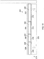
- FIG. 7 shows schematically a side view of an adjustable bed according to a second embodiment of the present invention.
- the bed comprises a fixed intermediate body support portion 1200, back/head support 1220, upper leg support 1240, and lower leg/foot support 1260, all supported by a main frame (base) 1300 and a sub-assembly (intermediate support) 1320 which is moveable relative to the main frame 1300.
- base main frame
- sub-assembly 1320 which is moveable relative to the main frame 1300.
- FIG. 7 to 9 only one side of the adjustable bed is shown schematically. It will be understood that in the illustrated arrangement the bed will be similarly constructed on both sides, as shown in the embodiments of Figures 1 to 6 , that is to say symmetrically along a longitudinal central axis of the bed.
- the body support sections 1200, 1220, 1240 and 1260 each comprise a support panel on which is mounted a mattress support cushion, which cushions combine to provide a so called "soft edge" mattress foundation.
- a mattress (not shown) sits on top of the support cushions as is well known in the art.
- the sub-assembly or intermediate support 1320 has slots 1410, 1420 within which run bearings 1430, 1440 mounted on shafts extending from the main frame of the base to permit the sub-assembly 1320 to move relative to the main frame 300 in a left/right sense as illustrated.
- Additional bearing 1442 is provided on the main frame for effecting movement of the sub-assembly with respect to the base during movement of the back support 1220 about its pivot axis.
- the bearing 1442 also provides for slightly elevating the sub-assembly during such movement as will be described below.
- a load-bearing member 1340 is attached to the underside of the back support 1220, and a load-bearing member 1360 is attached to the underside of the leg support 1240.
- the leg support load-bearing member 1360 has an angled surface 365, similar to the angles surface 46 in the first embodiment.
- Electrical linear motors 1480, 1580 are connected by pivotal connections 1490, 1590 respectively to the leg support 1240 and back support 1220 for raising these portions of the bed as shown in Figures 8 and 9 in order to adjust the position of a person lying on the bed.
- the leg support load-bearing member 1360 and back support load-bearing member 1340 respectively carry support bearings 1460, 1470 and 1560, 1570 which run in curved slots 1450, and 1550 respectively for supporting at least part of the load supported by the item of furniture.
- the bed according to the embodiment of Figures 7 to 9 is similar to that of the bed shown in Figures 1 to 6 .
- leg support drive motor 1480 has extended a threaded spindle 1485 to tilt the leg support 1240 upwards and clockwise (as illustrated), thus allowing the pivotally connected lower leg and foot support 1260 to move anti-clockwise (as illustrated) until it meets the angled surface 1365 of the leg support load-bearing member 1360.
- the leg support load-bearing member 1360 has moved with this action to the semi-raised position shown.
- the back support raising motor 1580 has extended the spindle 1585 to raise the back support upwards and anti-clockwise (as shown). This has the effect of moving the sub-assembly 1320 from left to right as illustrated with the slots 1410, 1420 moving from left to right on the support bearings 1430, 1440 and the sub-assembly 320 being slightly raised on the additional bearings 1442 and 1444.
- Figure 9 shows the corresponding position when the drive motors have fully extended the threaded spindles 1485, 1585 so that the bearings 1460, 1470, 1560, 1570 of the respective load-supporting members 1360, 1340 move within the sub-assembly slots 1450, 1550 from the position shown in Figure 7 to the final position shown in Figure 9 .
- the sub-assembly 1320 has accordingly moved further to the right on its support bearings 1430, 1440 in slots 1410, 1420 and has been slightly further raised by the additional bearings 1442.
- the upper leg support and lower leg/foot support portions 1240, 1260 are retained at the pre-determined angle achieved in Figure 7 due to the contact of the foot and lower leg support 1260 with the angled surface 1365 of load-bearing member 1360.
- the leg support 1240 and support 260 are pivotally connected together in known manner.
- the bearing 1442 follows the curvature of the semi-circular guide surface 441 on the underside of the load support member 1340 such that as the load bearing support member 1340 rotates about its pivot axis from the position shown in Figure 7 to that of Figure 9 , the reaction force generated between the bearing 1442 and the guide surface 1441 causes the sub-assembly 1320 to move relative to the base 1300, which relative movement is determined by engagement of the inclined slots 1420, 1430 with respective bearings 1430, 1440 rotatably fixed on the base 1300.
- FIGS 10 to 21 show schematically an adjustable bed 200 according to a third embodiment of the present invention.
- the bed 200 comprises an adjustable back support section 202, a fixed middle/intermediate support section 204, an adjustable upper leg support section 206 and lower leg support section 208.
- the bed 200 is shown in its lowered configuration with the back support section 202, middle support section 204 and leg support sections 206, 208 lowered where the adjacent support sections lie substantially flat above a base support 210.
- the support sections 202, 204, 206, 208 comprise respective adjacent flat planar panels 212, 214, 216, 218 which support respective adjacent mattress support cushions or pads 220, 222, 224, 226 which combine to provide a mattress support foundation on which a suitable mattress (not shown) is supported to provide a so called "soft edge" adjustable bed.
- the bed 200 is a double bed but the present embodiment contemplates beds of many different widths including standard single size beds to much larger doubles.
- the base support 210 comprises a generally rectangular frame constructed by a board type material which may be an engineering plastic, MDF, timber or other fibre type board for example.
- the base support frame 210 includes a pair of elongate lateral side panels 228, 230 which are joined together near their respective ends by cross member panels 232, 234 to form a rectangular box type structural support frame.
- the base support frame 210 constitutes the floor standing part of the bed 200 and in this respect the support frame may stand directly on the floor or be provided with castors, feet or the like as is well known in the art.
- An intermediate support in the form of a movable carriage 236 is mounted within the interior region of the base support frame 210 on the underside of the body support sections 202, 204, 206, 208.
- the intermediate support 236 can best be seen in the drawings of Figures 12 and 13 where the body support panels 212-218 and their associated mattress support cushions 220-226 are omitted from the drawings for clarity.
- Figure 12 the illustrated component parts of the bed are shown positioned with the bed in its normal flat configuration.
- Figure 13 the illustrated parts are shown with the bed positioned in a fully upright configuration.
- the intermediate support carriage comprises a pair of elongate parallel side panels 238, 240 disposed adjacent the lateral left and right hand side panels 228, 230 of the base support frame.
- the panels 238, 240 are symmetrically identical such that the mounting arrangement on one side of the bed is the same as the other.
- the panels are rigidly joined together by a pair of parallel cross members 242, 244 which are spaced apart along the length of the bed.
- the panels 238, 240 are preferably constructed from a board material such as MDF or an engineering plastic as commonly used in the furniture industry and suitable for CNC machining.
- the cross-members 242, 244 may be constructed from the same material as the side panels but may also be metal, preferably steel for supporting applied actuator loads to move the various body sections as will be more fully described below.
- the cross-members 242, 244 are each provided with respective actuator mounting brackets 246 at the mid-point along their length.
- the back support panel 212 is pivotally mounted to the intermediate support carriage by a pair of load support members 248 attached to and extending from the underside of the support panel 212.
- the load support members 248 are spaced apart and located at laterally spaced positions on the panel 212 so that they lie substantially adjacent to the respective side panels 238, 240 of the intermediate support on the internal side thereof such that rolling element bearings 250a, 250b, 250c ( Figures 14 , 15 and 16 ) rotatably mounted on the sides of the load bearing members 248 locate, and are held captive in, respective arcuate slots 252 in the respective panels 238, 240.
- the load bearing support members 248 constitute a connecting lever pivotally mounting the back rest support 202 with respect to the intermediate support.
- the upper leg support panel 216 is similarly pivotally mounted to the intermediate support carriage by a pair of load support members 254 attached to and extending from the underside of the support panel 216.
- the load support members 254 are spaced apart and located at laterally spaced positions on the panel 216 so that they lie substantially adjacent to the respective side panels 238, 240 of the intermediate support on the internal side thereof such that rolling element bearings 256a, 256b, 256c ( Figures 14 and 15 ) rotatably mounted on the sides of the load bearing members 254 locate, and are held captive in, respective arcuate slots 258 in the respective panels 238, 240.
- the mid-section panel 214 is fixed with respect to the intermediate support carriage immediately between the back and upper leg support panels 212, 216 in the lowered configuration of the bed as shown in Figure 10 .
- the lower leg support panel 218 is pivotally connected to the upper leg support panel 216 along their respective adjoining edges by hinges 260.
- the load bearing members 248 and 254 are substantially planar having a crescent shape and are designed such that they lie substantially flush, with a small clearance of a few millimetres or so, with the respective side panels 238, 240 of the intermediate support, within the envelope of the base support carriage in the lowered configuration of the bed as shown in Figures 11 and 12 , with the panels 212-218 lying substantially flat on or just above the top edge of the base support frame 210.
- the load bearing support members 248, 254 are each provided with inwardly projecting planar elements 266 which extend perpendicular to the plane of the support members to provide mounting members for engagement with and fixing to the underside of the respective panels 212 and 216.
- the load bearing support members 248 are rigidly connected together by means of a cross-member 262, and similarly the load bearing support members 254 are connected together by a cross-member 264.
- the cross-members 262, 264 are each provided with actuator mounting brackets 268 at a mid-point along their length, each for connection to one end of a respective linear actuator (not shown).
- each load bearing member 248 is provided with rolling element bearings 250a, 250b, 250c located on that side of the support member facing the adjacent side panel of the intermediate support carriage.
- the bearings 250a and 250b are of similar construction and comprise a single rolling element bearing mounted on an upstanding pin extending from the surface of the load bearing member.
- the third bearing 250c is slightly different in that it comprises a pair of bearing elements 250c' and 250c" aligned coaxially on a longer pin. This arrangement is shown further in the plan view of bearing 250c in Figure 15 where the outer most bearing element 250c" is located approximately twice the distance from the load bearing support member than the first bearing element 250c'.
- the bearings 250a, 250b and 250c are located at positions indicated 270a, 270b and 270c on the other side of the support member 248 shown in the drawings of Figures 11-13 .
- the bearing arrangement on the load bearing support members 254 is similar to that described above in relation to support members 248, except that is that all three bearings 256a, 256b and 256c are of the single element type as 250a and 250b, and positioned respectively at positions 272a, 272b and 272c, as indicated on the reverse side of the support members in Figures 11-13 .
- bearings 250a, 250b and 250c' are located in slots 252 so thai the movement of the support members is constrained by the movement of the bearings in the slots 252.
- This provides the panel 212 and hence the back support section 202 with pivotal movement, with respect to the intermediate support, with the pivot axis defined by the centre of curvature of the slots 252 and with the extent of travel being determined by the length of the slot and the separation of the bearing elements 250a and 250c' in the slot.
- the range of pivotal movement of the support member 248 is defined by the ends of the slot 252 and the separation of the respective bearings 250a and 250c' by abutment of a respective one of the bearings with a respective end of the slot.
- the bearings 250a and 250c' may be spaced apart by a maximum distance corresponding to approximately half the length of the curved slot 252
- the position of the slots 252 and 258 can best be seen in the drawing of Figure 16 where the side panel 228 has been omitted for clarity for the purpose of illustrating the adjustment arrangement of the bed in greater detail.
- the panels 228 of the intermediate support is shown in the side elevation drawing of Figure 16 it is to be understood that the panels 228, 230 are substantially identical to one another, each having a pair of curved guide slots 252, 258 for accommodating support bearings 250a-c' and 256a-c as previously described.
- the first guide slot 250 is provided in the rearward half of the panel 228 and the second slot 258 in the forward half of the panel.
- the centre of curvature 274 of the first slot 258 is positioned at the adjoining upper edges of the adjacent mattress support cushions 222, 224 so that in use adjustment of the bed between its various positions does not cause compression of the mattress (not shown but located on top of the support cushions in use) in the region of the adjoining edges of the support cushions.
- the centre of curvature 276 of the second slot 252 is positioned at the adjoining edges of the adjacent mattress support cushions 220, 222 so that in use adjustment of the bed between its various positions does not cause compression of the cushions or the mattress in the region of these adjoining edges.
- the position of the bearing elements 250a-c and 256a-c is also illustrated in the drawing of Figure 17 in which the side panel 240 is also removed to show further detail.
- the position of the front and rear slots is indicated by slot inserts 252' and 258' which are illustrated in their in-situ position as if the side panel 240 were present.
- the inserts 252' and 256' provide a hardwearing bearing surface for the bearing elements 250a-c' and 256a-c and fit in appropriately sized slots in the respective side panels of the intermediate support carriage and function in a similar way to the slot inserts 32, 38 in previous embodiments.
- FIG. 16 and 17 also illustrate the manner in which the intermediate support carriage is movably mounted with respect to the base support 210.
- Each side panel 238, 240 is provided with three rolling element bearings 280a-c, positioned at spaced apart locations along the length of the respective panels, mounted on bearing pins upstanding from the surface of the respective panel and projecting towards the adjacent outer panel 228, 230 of the base support in which bearing engagement slots 282a-c are provided for receiving respective slot inserts 282a'-c.
- the inserts 282a'-c' are shown in their respective in-situ positions in the drawings of Figures 16 and 17 although the side panel 240 in which they are mounted has been omitted for the purpose of illustration.
- the inserts 282a'-c' are located in blind slots provided on the inward facing surface of the respective side panels 228, 230. Part of the rear slot insert 282c' can be seen in the drawing of Figure 11 and part of the forward slot insert 282a' in the drawing of Figure 18 .
- the slots 282a-c and corresponding inserts 282a'-c' are linear and aligned along the length of the panels 228, 230 to guide the intermediate support carriage in a non-inclined linear parallel direction with respect to the base support during adjustment of the bed between its various positions.
- the slots and inserts are substantially identical and generally equally spaced along the mid part of the bed.
- the slots 280a-c are blind in that they do not create apertures in the side of the panels 228, 230, but are deep enough to accommodate the respective inserts and rolling element bearings 280a-c fixed to the intermediate support carriage. This arrangement constitutes the aforementioned first guide means in this embodiment of the invention.
- a fourth slot 284 and insert 284' combination is provided towards the rear of the panels 228, 230 which accommodates the bearing element 250c" mounted on the rear load bearing support member 248.
- This arrangement constitutes the aforementioned second guide means in this embodiment.
- the fourth slot 284 is curvilinear having first and second curved sections 286, 288.
- the first section 286 has a curvature that matches that of the slot 252 and is coincident with the rear part of that slot when the bed occupies a position between the fully lowered position and the half raised position of Figure 19 . In this range of relative movement the bearing 250c" moves freely in the first section 286 as the back support is raised to the half raised position of Figure 19 , then the curvature and direction of the slot changes abruptly.
- the second section 288 has a different centre of curvature to the first section and rises more gently along the length of the panel 228, 230 than the first section.
- This change in curvature generates a reaction force between the bearing element 250c" and the second section 288 of the slot, which forces the intermediate support carriage forward relative to the base support along guides 280a-c as a turning moment is applied (by one of the actuators or otherwise)n to the back support section of the bed.
- the bearing 250c" is forced to move along the second section of the slot and the resistance that is generated by the reaction of the bearing element with the upper surface of the slot 288 drives the intermediate section forward with respect to the base support.
- This resultant motion is similar to the relative motion of the support and intermediate support sections of the chair arrangements of the previous embodiments where the back rest is moved.
- similar coordinated movement occurs when the back support section of the bed is moved when it is raised to provide a backrest in the upright configuration of the bed.
- the bed described in this embodiment also functions as a zero wall item of furniture. This is particularly advantageous in the context of adjustable beds as it enables the user to retain access to beside furniture etc, as the relative position of the user relative to that furniture does not change when the back rest is raised or lowered, as the movement is compensated by the linear forward or backward movement of the intermediate support carriage on which the body support sections are mounted.
- movement of the bed through the various positions shown is effected by means of two linear electrical actuators of the type commonly used in adjustable furniture arrangements, including a first actuator (not shown) connected between bracket 246 on cross-member 244 and bracket 268 on cross-member 262 for moving the back support section 202, and a second linear actuator (not shown) connected between bracket 246 on cross-member 242 and bracket 268 on cross-member 264 for moving the leg support sections 206.
- a first actuator (not shown) connected between bracket 246 on cross-member 244 and bracket 268 on cross-member 262 for moving the back support section 202
- a second linear actuator (not shown) connected between bracket 246 on cross-member 242 and bracket 268 on cross-member 264 for moving the leg support sections 206.
- the relative position of the linear actuator jacks on the underside of the bed 200 is particularly advantageous, first because the force vector applied by the actuators actually follows the movement of the load bearing support panels as they move, since both ends of the actuator are pivotally connected to the respective aforementioned brackets, and second because the force vector is always offset, by a significant distance, to the respective pivot axis, 274, 276 about which the turning moment generated by the actuator is applied, thus providing the powered arrangement with considerable mechanical advantage.
- each load bearing support member 254 serves to limit the extent of pivotal movement at the hinge connection 260 between the panels 216 and 218.
- both sections 208 and 206 begin to lift but hinge apart until the position of Figure 19 is reached when the abutment surface 278 engages the underside of the panel 218. This provides a useful "knee break" function where the users' lower legs are not raised until a comfortable relative position of the upper and lower part of the limbs is first achieved.
Description
- This invention relates to adjustable furniture and in particular concerns adjustable beds having adjustable body-support sections which can be moved to adjust the position of a user.
- Adjustable beds are known for example from
US2009/0193587 which discloses an adjustable bed in which a back/head support section and leg/foot support sections are pivotably mounted next to a fixed intermediate support section. Electrical linear actuators are attached 1o the underside of both the back and leg support sections for moving those sections between horizontal and inclined positions. The linear actuators act more-or-less directly on the underside of the moveable body support portions. Each of the body support sections is provided with a flexible cushion and in order to prevent crushing of the adjacent ends of the respective cushions, during adjustment of the bed, the bed includes independently moveable front and rear carriages powered by linear actuators supported on a stationary base. The back/head support section is pivotally secured to one carriage and moves linearly with it. The leg and foot support sections are pivotally connected together and are supported by the other carriage and move with it. This arrangement prevents crushing of the respective cushions and adjacent parts of a support mattress supported on the cushions in use, that is when the bed is raised from the lying flat position to its raised position. - The adjustable bed disclosed in
US2009/0193587 provides a solution to the problem of compression of the adjoining edges of the adjacent body support cushions due to compression points being developed when the respective sections of the bed are moved to their raised positions. This arrangement requires a minimum of four linear actuators, one each for moving the pivotable parts of the bed and one for each moveable carriage. The moveable front and rear carriages and associated actuators adds considerable cost and weight to the adjustable bed. This and other known adjustable bed arrangements are mechanically complex and expensive to manufacture. There is a requirement therefore for a lighter and less expensive adjustment mechanism for articles of adjustable furniture having sufficient strength, weight carrying capacity and durability. - According to an aspect of the present invention there is provided an article of furniture in the form of an adjustable bed (10), the said bed comprising a base (20), the base being a rectangular box-type structure having a pair of lateral side panels (22) joined at their respective end by a respective end panel (24) to close the structure to create a divan type load bearing frame, and at least two body-support portions (12,14,16) mounted with respect to the base (20) to allow angular adjustment of their relative positions to alter the configuration of the bed (10); the base (20) supporting the body support portions (12,14,16); the or each body support portion having at least one load-bearing member (36,40) extending on an underside thereof and supported by bearing means (38.42) arranged to run on a curved support (26,28) such that the or each moveable body-support portion (12,14,16) is pivotally mounted with respect to the said base (20) about a respective pivot axis defined by the centre of curvature of the respective curved support (26,28); the curved supports are curved slots provided in the lateral side panels of the base; the pivot axis of the or each movable body-support portion (12,14,16) being positioned above the said base (20) in a plane offset from the top edge thereof; and actuator means (1480,1580) for angularly moving said body-support portion(s) to effect the said angular adjustment, wherein at least one pair of said load-bearing members (36,40) project from the or each movable body-support portion(s), in which the load-bearing members are spaced from each other towards the respective sides of the base, wherein the body-support portions comprise at least an adjustable upper leg support (14) having the said load-bearing member projecting from the leg support, the upper leg support (14) has an adjustable lower leg and foot support (16) pivotally connected thereto.
- According to the invention the pivot axis of the or each movable body-support portion is positioned above the said base in a plane offset from the top edge thereof. Preferably the pivot axis or axes is/are positioned in a plane offset from the base by an amount substantially corresponding to the thickness of the body support portions such that the offset plane is substantially coincident with an upper support surface of the body support portions when in a flat horizontal position. The offset nature of the pivot axis or axes can substantially eliminate interference of the respective body support portions when they move with respect to one another as the pivot axis may be positioned at a common hinge position between adjacent body support portions. In preferred arrangements where the body support portions include a compressible cushion or other compressible support means interference at the respective adjacent ends can be readily avoided.
- In preferred embodiments, the load bearing member comprises at least one plate-like projection from the underside of the relevant body-support portion. The invention also contemplates alternative structures, for example struts or tubular frames, which could be used as the load bearing members(s). The base may comprise a support frame of any suitable material including metal, engineering plastic or suitable board material, for example timber, MDF or other suitable fibre board.
- In preferred embodiments the bearing means is carried by the load bearing member. According to the invention one or more curved slots are provided in the lateral side panels of the base to receive respective bearing means for supporting and guiding the body support portions with respect to the base.
- In preferred embodiments the pair of load bearing members lie substantially parallel with respective lateral side panels of the base. This arrangement readily provides for a compact arrangement in which the load bearing members are positioned closely adjacent to the respective lateral side panels away from other moving parts of the furniture, including the actuator means which may preferably be located within the structure of the base. The bearing means carried by the load bearing member may be of any appropriate kind, for example roller bearings mounted on a shaft. In preferred embodiments, the bearing means is carried by the said load bearing member and the curved track is provided on or in the base. It is however possible to use a reverse arrangement in which the bearing means is carried on the base and runs in a track in or on the load bearing projection.
- In preferred embodiments the load bearing members lie substantially parallel with respective lateral side panels of the base. Each pair of load bearing members may be connected together by a respective cross member, in addition to the respective body support portion, with the cross member preferably extending on the underside of the body support portion. Such a cross member will have the effect of stiffening the moveable structure and also provide an attachment point for connection to a powered actuator.
- In preferred arrangements the or each curved support is provided on or in a respective side panel of the base.
- According to the invention the or each moveable body support portion is pivotably mounted with respect to the base about a respective pivot axis defined by the centre of curvature of the respective curved support(s). In this way it is possible to define the position of the pivot axis at any appropriate position within the article of furniture.
- In preferred embodiments the load bearing member comprises at least one substantially semi-circular planar element, or part thereof, positioned on the underside of the body support portion. In this way the respective load bearing members may lie within the space envelope, or depth dimension, of the base when the respective body support portions lie flat in their lowered position. In this way the load bearing members may be wholly contained within the base when the respective body support portions are lowered, or at least with no part of the respective load bearing members protruding above, or below, the lateral sides of the base.
- In preferred embodiments the actuator means is arranged to apply the adjustment force substantially to the underside of the moveable body support portion to which it is attached. In this way the actuator loads may be minimised by increasing the perpendicular distance between the pivot axis of the respective body support portion and the point of application of the actuator load.
- In preferred embodiments the actuator means comprises of at least one electric motor driving an extended threaded spindle. In preferred embodiments, actuator means, preferably a single actuator, is associated with each of the relatively moveable body support portions so that each may be operated independently.
- In preferred embodiments the body support portion comprises at least a seat support and an adjustable back support having the said load bearing member or members projecting from the back support.
- The body support portion may comprise a leg and foot support having the load bearing member projecting from the leg support. In preferred embodiments the leg support includes an adjustable foot and calf support pivotably attached to the main part of the leg support. Preferably the foot/calf support is arranged to pivot apart from the leg support during angular adjustment of the leg support, and the load bearing member projecting from the leg support provides a stop that stops the pivoting of the foot support at a predetermined angle relative to the leg support. In this way the raised configuration of the leg support is determined by the position of the stop, the position being predetermined by human anatomical considerations thereby to provide for maximum comfort of the user.
- In preferred embodiments the article of furniture is an adjustable bed, adjustable between a sitting position and a lying position, the bed having a seat portion fixed with respect to the base, an adjustable back portion on one side of the seat portion and an adjustable leg support and foot/calf support on the other side of the fixed seat portion.
- The various embodiments of the present invention will now be more particularly described, by way of example only, with reference to the accompanying drawings; in which:
-
Figure 1 is a perspective view from the front of an adjustable bed according to an embodiment of the invention; -
Figure 2 is a perspective view from the rear of the bed offigure 1 ; -
Figure 3 is a perspective view from the side of the bed offigures 1 and2 ; -
Figure 4 is a perspective view of the bed offigures 1 to 3 from below; -
Figure 5 is a side elevation view of the bed offigures 1 to 4 ; -
Figure 6 is a plan view from below the bed offigures 1 to 5 . -
Figure 7 shows an adjustable bed according to another embodiment of the invention in a user lying position; -
Figure 8 shows the bed offigure 7 having been adjusted into a user semi-recumbent position; -
Figure 9 shows the bed raised into a more upright or user sitting position. -
Figure 10 is a side elevation view of an adjustable bed according to a further embodiment of the present invention; -
Figure 11 is a perspective view from below of the underside of the adjustable bed ofFigure 10 ; -
Figure 12 is a perspective view from above of the adjustable bed ofFigure 10 , with various parts omitted for clarity; -
Figure 13 is a perspective view from above showing the same component parts of the bed ofFigure 10 , with the parts positioned in a raised configuration of the bed; -
Figure 14 is a perspective view of component parts of the bed ofFigure 10 ; -
Figure 15 is a plan view of the parts shown inFigure 14 ; -
Figure 16 is a side elevation similar to that ofFigure 10 with an outer panel of the bed omitted to show internal detail; -
Figure 17 is a similar view to that of Figure 31 with a further panel omitted; -
Figure 18 is a perspective view from below showing the underside of the bed when in a raised position; -
Figure 19 is a side elevation view similar to that ofFigure 17 with the bed in a part raised position; -
Figure 20 is a side elevation view similar to that ofFigure 19 with the bed raised further; and -
Figure 21 is a side elevation view similar toFigure 20 with the bed in its fully raised position. - Referring to the drawings.
Figures 1 to 6 schematically show anadjustable bed 10 according to a first embodiment of the present invention. Thebed 10 comprises a back/head support panel 12, an upperleg support panel 14 and a foot and lowerleg support panel 16. Thepanels base 20. InFigures 1 to 6 thebed 10 is shown in an upright configuration with thepanels body support panels 12 14 and 16 combine with an intermediate support panel (not shown). The intermediate panel is fixed in relation to the base between theback support panel 12 and the upperleg support panel 14 to define a substantially flat horizontal platform. The various body support panels each support a mattress support cushion (not shown) which cushions combine to provide a mattress foundation for supporting a mattress, as is well known to those skilled in the art of adjustable beds. - The
base 20 comprises a generally rectangular frame constructed from a board type material, for example an engineering plastic, wood, MDF or other fibreboard material. Theframe 20 includes a pair of elongatelateral side panels 22 which are joined together at the respective ends byend panels 24 to form a rectangular box type structural load bearing frame. Theside panels 22 are substantially identical, each having a pair ofcurved guide slots respective support bearings first guide slot 26 is provided in the rearward half of thepanel 22 and asecond slot 28 in the forward half of the panel. The frame of the base is reinforced by respective front, rear andcentral cross-members respective side panels 22 as best seen inFigure 4 . - The
back support panel 12 is pivotally mounted to the base by a pair of load bearingsupport members 36 attached to and extending from the underside of thesupport panel 12. The loadbearing support members 36 are spaced apart and located on opposite sides of thepanel 12 so that they lie substantially adjacent to therespective side panels 22 of the base on the inner side thereof such thatroller bearings 38 rotatably mounted on the sides of theload bearing members 36 locate, and are held captive in, therespective slots 26. As can best be seen in the drawing ofFigure 5 eachload bearing member 36 is provided with a pair ofroller bearings 38 spaced apart by a distance corresponding to approximately half the length of thecurved slot 26. In this way the ends of the slot define the range of pivotal movement of thesupport panel 12 about its pivot axis, as defined by the centre of curvature of the slot, by abutment of one of thebearings 38 with a respective end of the slot. - The
load bearing members 36 are substantially semi circular in shape and are designed such that they lie substantially flush against therespective side panels 22, within the envelope of the base frame. When occupying their lowered position (not shown) thepanel 12 lies substantially flat on or just above the top edge of theframe 20. - The
roller bearings 38 are preferably mounted on shafts extending from theload bearing members 36 so that they are free to rotate and thereby move freely within therespective slots 26. - The upper
leg support panel 14 at the forward end of the bed is similarly pivotally connected to the frame by means of a pair ofload bearing members 40 and associatedroller bearings 42 positioned in theforward slots 28. The upperleg support panel 14 is fixed to anupper edge 44 of theload bearing members 40. The lower leg/foot support panel 16 is hinged to thepanel 14 along their respective adjoining edges. - The
curved slots base support frame 20. In preferred embodiments the centres of curvature of theslots respective support panels - The length of the
respective slots - The
load bearing member 40 is attached to the underside of the upperleg support panel 14. The leg supportload bearing member 40 has an angledsurface 46 which acts as a mechanical stop so that the upper leg support and the lower leg/foot support panels panel 16 with theangled surface 46. - As can be best seen in the plan view from below in
Figure 6 the respectiveload bearing members 36 of the back support and theload bearing members 40 of the leg support panels are joined together not only by therespective support panels respective cross members attachment brackets 52 for connection to one end of an actuator, for example an electric linear actuator, the other end of which maybe mounted on thecross member 34 of thebase 20. Thus, it will be understood that movement of the adjustable body support portions may be effected by extension of the respective actuators to cause movement of theload bearing members respective slots -
Figure 7 shows schematically a side view of an adjustable bed according to a second embodiment of the present invention. The bed comprises a fixed intermediatebody support portion 1200, back/head support 1220,upper leg support 1240, and lower leg/foot support 1260, all supported by a main frame (base) 1300 and a sub-assembly (intermediate support) 1320 which is moveable relative to themain frame 1300. In the drawings ofFigures 7 to 9 only one side of the adjustable bed is shown schematically. It will be understood that in the illustrated arrangement the bed will be similarly constructed on both sides, as shown in the embodiments ofFigures 1 to 6 , that is to say symmetrically along a longitudinal central axis of the bed. In the embodiment ofFigures 7 to 9 thebody support sections - The sub-assembly or
intermediate support 1320 hasslots bearings Additional bearing 1442 is provided on the main frame for effecting movement of the sub-assembly with respect to the base during movement of theback support 1220 about its pivot axis. Thebearing 1442 also provides for slightly elevating the sub-assembly during such movement as will be described below. - A load-
bearing member 1340 is attached to the underside of theback support 1220, and a load-bearing member 1360 is attached to the underside of theleg support 1240. The leg support load-bearing member 1360 has an angled surface 365, similar to the angles surface 46 in the first embodiment. - Electrical
linear motors pivotal connections leg support 1240 andback support 1220 for raising these portions of the bed as shown inFigures 8 and9 in order to adjust the position of a person lying on the bed. The leg support load-bearing member 1360 and back support load-bearing member 1340 respectively carrysupport bearings curved slots Figures 7 to 9 is similar to that of the bed shown inFigures 1 to 6 . - The same part numbering is used in
Figures 8 and9 to show the bed in respective partly raised and fully raised positions. InFigure 8 , the legsupport drive motor 1480 has extended a threadedspindle 1485 to tilt theleg support 1240 upwards and clockwise (as illustrated), thus allowing the pivotally connected lower leg andfoot support 1260 to move anti-clockwise (as illustrated) until it meets theangled surface 1365 of the leg support load-bearing member 1360. The leg support load-bearing member 1360 has moved with this action to the semi-raised position shown. - Similarly, the back
support raising motor 1580 has extended thespindle 1585 to raise the back support upwards and anti-clockwise (as shown). This has the effect of moving the sub-assembly 1320 from left to right as illustrated with theslots support bearings additional bearings - The angular motion of the load-
bearing members bearings slots Figure 7 to those illustrated inFigure 8 , thus supporting at least part of the load which, in the prior art, would be bom by the extension motors and spindles alone. -
Figure 9 shows the corresponding position when the drive motors have fully extended the threadedspindles bearings members sub-assembly slots Figure 7 to the final position shown inFigure 9 . Thesub-assembly 1320 has accordingly moved further to the right on itssupport bearings slots additional bearings 1442. The upper leg support and lower leg/foot support portions Figure 7 due to the contact of the foot andlower leg support 1260 with theangled surface 1365 of load-bearing member 1360. Theleg support 1240 andsupport 260 are pivotally connected together in known manner. - It is to be understood that the
bearing 1442 follows the curvature of the semi-circular guide surface 441 on the underside of theload support member 1340 such that as the load bearingsupport member 1340 rotates about its pivot axis from the position shown inFigure 7 to that ofFigure 9 , the reaction force generated between thebearing 1442 and theguide surface 1441 causes the sub-assembly 1320 to move relative to thebase 1300, which relative movement is determined by engagement of theinclined slots respective bearings base 1300. - As can be next seen in the embodiment of
Figures 7 to 9 the centres ofcurvature arcuate guide slots seat portion 1200 with the adjacentbody support portions Figures 8 and9 there is no interference between the respective upper adjoining edges of thesupports -
Figures 10 to 21 show schematically anadjustable bed 200 according to a third embodiment of the present invention. Thebed 200 comprises an adjustableback support section 202, a fixed middle/intermediate support section 204, an adjustable upperleg support section 206 and lowerleg support section 208. - In
Figures 10 to 12 andFigures 16 and17 thebed 200 is shown in its lowered configuration with theback support section 202,middle support section 204 andleg support sections base support 210. Thesupport sections planar panels pads bed 200 is a double bed but the present embodiment contemplates beds of many different widths including standard single size beds to much larger doubles. - As can best be seen in
Figure 11 , thebase support 210 comprises a generally rectangular frame constructed by a board type material which may be an engineering plastic, MDF, timber or other fibre type board for example. Thebase support frame 210 includes a pair of elongatelateral side panels cross member panels base support frame 210 constitutes the floor standing part of thebed 200 and in this respect the support frame may stand directly on the floor or be provided with castors, feet or the like as is well known in the art. - An intermediate support in the form of a
movable carriage 236 is mounted within the interior region of thebase support frame 210 on the underside of thebody support sections intermediate support 236 can best be seen in the drawings ofFigures 12 and13 where the body support panels 212-218 and their associated mattress support cushions 220-226 are omitted from the drawings for clarity. InFigure 12 the illustrated component parts of the bed are shown positioned with the bed in its normal flat configuration. InFigure 13 the illustrated parts are shown with the bed positioned in a fully upright configuration. The intermediate support carriage comprises a pair of elongateparallel side panels hand side panels panels parallel cross members panels actuator mounting brackets 246 at the mid-point along their length. - The
back support panel 212 is pivotally mounted to the intermediate support carriage by a pair ofload support members 248 attached to and extending from the underside of thesupport panel 212. Theload support members 248 are spaced apart and located at laterally spaced positions on thepanel 212 so that they lie substantially adjacent to therespective side panels element bearings Figures 14 ,15 and16 ) rotatably mounted on the sides of theload bearing members 248 locate, and are held captive in, respectivearcuate slots 252 in therespective panels bearing support members 248 constitute a connecting lever pivotally mounting theback rest support 202 with respect to the intermediate support. - The upper
leg support panel 216 is similarly pivotally mounted to the intermediate support carriage by a pair ofload support members 254 attached to and extending from the underside of thesupport panel 216. Theload support members 254 are spaced apart and located at laterally spaced positions on thepanel 216 so that they lie substantially adjacent to therespective side panels element bearings Figures 14 and15 ) rotatably mounted on the sides of theload bearing members 254 locate, and are held captive in, respectivearcuate slots 258 in therespective panels - The
mid-section panel 214 is fixed with respect to the intermediate support carriage immediately between the back and upperleg support panels Figure 10 . The lowerleg support panel 218 is pivotally connected to the upperleg support panel 216 along their respective adjoining edges by hinges 260. - The
load bearing members respective side panels Figures 11 and12 , with the panels 212-218 lying substantially flat on or just above the top edge of thebase support frame 210. The loadbearing support members planar elements 266 which extend perpendicular to the plane of the support members to provide mounting members for engagement with and fixing to the underside of therespective panels - The load
bearing support members 248 are rigidly connected together by means of a cross-member 262, and similarly the load bearingsupport members 254 are connected together by across-member 264. The cross-members 262, 264 are each provided withactuator mounting brackets 268 at a mid-point along their length, each for connection to one end of a respective linear actuator (not shown). - As can best be seen in the drawing of
Figure 14 eachload bearing member 248 is provided with rollingelement bearings bearings third bearing 250c is slightly different in that it comprises a pair of bearingelements 250c' and 250c" aligned coaxially on a longer pin. This arrangement is shown further in the plan view of bearing 250c inFigure 15 where the outer mostbearing element 250c" is located approximately twice the distance from the load bearing support member than thefirst bearing element 250c'. Thebearings support member 248 shown in the drawings ofFigures 11-13 . - The bearing arrangement on the load bearing
support members 254 is similar to that described above in relation to supportmembers 248, except that is that all threebearings Figures 11-13 . - On both sides of the
bed bearings slot 258 so that the movement of the support members is constrained by the movement of the bearings in thoseslots 258. This provides thepanel 216 and hence the upperleg support section 206 with pivotal movement, with respect to the intermediate support, with the pivot axis defined by the centre of curvature of theslots 258 and with the extent of travel being determined by the length of the slot and the separation of thebearing elements support members 254 is defined by the ends of theslot 258 and the separation of therespective bearings bearings curved slot 258. - Similarly
bearings slots 252 so thai the movement of the support members is constrained by the movement of the bearings in theslots 252. This provides thepanel 212 and hence theback support section 202 with pivotal movement, with respect to the intermediate support, with the pivot axis defined by the centre of curvature of theslots 252 and with the extent of travel being determined by the length of the slot and the separation of thebearing elements support member 248 is defined by the ends of theslot 252 and the separation of therespective bearings bearings curved slot 252 - The position of the
slots Figure 16 where theside panel 228 has been omitted for clarity for the purpose of illustrating the adjustment arrangement of the bed in greater detail. Although only one of thepanels 228 of the intermediate support is shown in the side elevation drawing ofFigure 16 it is to be understood that thepanels curved guide slots support bearings 250a-c' and 256a-c as previously described. The first guide slot 250 is provided in the rearward half of thepanel 228 and thesecond slot 258 in the forward half of the panel. The centre ofcurvature 274 of thefirst slot 258 is positioned at the adjoining upper edges of the adjacent mattress support cushions 222, 224 so that in use adjustment of the bed between its various positions does not cause compression of the mattress (not shown but located on top of the support cushions in use) in the region of the adjoining edges of the support cushions. Likewise The centre ofcurvature 276 of thesecond slot 252 is positioned at the adjoining edges of the adjacent mattress support cushions 220, 222 so that in use adjustment of the bed between its various positions does not cause compression of the cushions or the mattress in the region of these adjoining edges. - The position of the
bearing elements 250a-c and 256a-c is illustrated in the drawing ofFigure 16 when the bed is in its lowered configuration, with the bearing 256c at the rear end of thefront slot 258 and thebearing 250a positioned at the front end of the rear slot 250. - The position of the
bearing elements 250a-c and 256a-c is also illustrated in the drawing ofFigure 17 in which theside panel 240 is also removed to show further detail. In this drawing the position of the front and rear slots is indicated by slot inserts 252' and 258' which are illustrated in their in-situ position as if theside panel 240 were present. The inserts 252' and 256' provide a hardwearing bearing surface for thebearing elements 250a-c' and 256a-c and fit in appropriately sized slots in the respective side panels of the intermediate support carriage and function in a similar way to the slot inserts 32, 38 in previous embodiments. In the drawing ofFigure 17 the relative position of theslots support members Figure 17 also more clearly illustrates the profile of the load bearingsupport members angled abutment face 278 at the forward end of the load bearingsupport members 254, the purpose of which will be described in detail below. - The drawings of
Figures 16 and17 also illustrate the manner in which the intermediate support carriage is movably mounted with respect to thebase support 210. Eachside panel element bearings 280a-c, positioned at spaced apart locations along the length of the respective panels, mounted on bearing pins upstanding from the surface of the respective panel and projecting towards the adjacentouter panel engagement slots 282a-c are provided for receiving respective slot inserts 282a'-c. Theinserts 282a'-c' are shown in their respective in-situ positions in the drawings ofFigures 16 and17 although theside panel 240 in which they are mounted has been omitted for the purpose of illustration. Theinserts 282a'-c' are located in blind slots provided on the inward facing surface of therespective side panels rear slot insert 282c' can be seen in the drawing ofFigure 11 and part of theforward slot insert 282a' in the drawing ofFigure 18 . - The
slots 282a-c andcorresponding inserts 282a'-c' are linear and aligned along the length of thepanels slots 280a-c are blind in that they do not create apertures in the side of thepanels element bearings 280a-c fixed to the intermediate support carriage. This arrangement constitutes the aforementioned first guide means in this embodiment of the invention. - A
fourth slot 284 and insert 284' combination is provided towards the rear of thepanels bearing element 250c" mounted on the rear load bearingsupport member 248. This arrangement constitutes the aforementioned second guide means in this embodiment. Thefourth slot 284 is curvilinear having first and secondcurved sections first section 286 has a curvature that matches that of theslot 252 and is coincident with the rear part of that slot when the bed occupies a position between the fully lowered position and the half raised position ofFigure 19 . In this range of relative movement thebearing 250c" moves freely in thefirst section 286 as the back support is raised to the half raised position ofFigure 19 , then the curvature and direction of the slot changes abruptly. Thesecond section 288 has a different centre of curvature to the first section and rises more gently along the length of thepanel bearing element 250c" and thesecond section 288 of the slot, which forces the intermediate support carriage forward relative to the base support alongguides 280a-c as a turning moment is applied (by one of the actuators or otherwise)n to the back support section of the bed. As the back support section is raised beyond the intermediate position ofFigure 19 thebearing 250c" is forced to move along the second section of the slot and the resistance that is generated by the reaction of the bearing element with the upper surface of theslot 288 drives the intermediate section forward with respect to the base support. This resultant motion is similar to the relative motion of the support and intermediate support sections of the chair arrangements of the previous embodiments where the back rest is moved. In the present embodiment similar coordinated movement occurs when the back support section of the bed is moved when it is raised to provide a backrest in the upright configuration of the bed. Thus, the bed described in this embodiment also functions as a zero wall item of furniture. This is particularly advantageous in the context of adjustable beds as it enables the user to retain access to beside furniture etc, as the relative position of the user relative to that furniture does not change when the back rest is raised or lowered, as the movement is compensated by the linear forward or backward movement of the intermediate support carriage on which the body support sections are mounted. - The relative positions of the various parts of the bed as the configuration of the bed is adjusted from the fully lowered configuration to the fully raised configuration can be seen by following the sequence of drawings of
Figures 17 (fully lowered).Figure 19 (half raised).Figure 20 (intermediate between half raised and fully raised) though toFigure 21 (fully raised). Each drawing presents the same part side view of the bed construction asFigure 17 and illustrates the relative positions of the bearings in the respective slots as the bed is moved from one configuration to another. - In the illustrated embodiment movement of the bed through the various positions shown is effected by means of two linear electrical actuators of the type commonly used in adjustable furniture arrangements, including a first actuator (not shown) connected between
bracket 246 oncross-member 244 andbracket 268 oncross-member 262 for moving theback support section 202, and a second linear actuator (not shown) connected betweenbracket 246 oncross-member 242 andbracket 268 oncross-member 264 for moving theleg support sections 206. It will be understood by those skilled in the art that the relative position of the linear actuator jacks on the underside of thebed 200 is particularly advantageous, first because the force vector applied by the actuators actually follows the movement of the load bearing support panels as they move, since both ends of the actuator are pivotally connected to the respective aforementioned brackets, and second because the force vector is always offset, by a significant distance, to the respective pivot axis, 274, 276 about which the turning moment generated by the actuator is applied, thus providing the powered arrangement with considerable mechanical advantage. - As can best be seen by comparison of the drawings of
Figures 17 and19 theangled abutment surface 278 at the end of each load bearingsupport member 254 serves to limit the extent of pivotal movement at thehinge connection 260 between thepanels sections Figure 19 is reached when theabutment surface 278 engages the underside of thepanel 218. This provides a useful "knee break" function where the users' lower legs are not raised until a comfortable relative position of the upper and lower part of the limbs is first achieved.
Claims (12)
- An article of furniture in the form of an adjustable bed (10), the said bed comprising a base (20), the base being a rectangular box-type structure having a pair of lateral side panels (22) joined at their respective end by a respective end panel (24) to close the structure to create a divan type load bearing frame, and at least two body-support portions (12,14,16) mounted with respect to the base (20) to allow angular adjustment of their relative positions to alter the configuration of the bed (10); the base (20) supporting the body support portions (12,14,16); the or each body support portion having at least one load-bearing member (36,40) extending on an underside thereof and supported by bearing means (38.42) arranged to run on a curved support (26,28) such that the or each moveable body-support portion (12,14,16) is pivotally mounted with respect to the said base (20) about a respective pivot axis defined by the centre of curvature of the respective curved support (26,28); the curved supports are curved slots provided in the lateral side panels of the base; the pivot axis of the or each movable body-support portion (12,14,16) being positioned above the said base (20) in a plane offset from the top edge thereof; and actuator means (1480,1580) for angularly moving said body-support portion(s) to effect the said angular adjustment, wherein at least one pair of said load-bearing members (36,40) project from the or each movable body-support portion(s), in which the load-bearing members are spaced from each other towards the respective sides of the base, wherein the body-support portions comprise at least an adjustable upper leg support (14) having the said load-bearing member projecting from the leg support, the upper leg support (14) has an adjustable lower leg and foot support (16) pivotally connected thereto.
- An article of furniture as claimed in Claim 1 wherein the said pivot axis or axes is/are positioned in a plane offset from the said base (20) by an amount substantially corresponding to the thickness of the body support portions (12,14,16) such that the said offset plane is substantially coincident with an upper support surface of the said body support portions (12,14,16) when in a flat horizontal position, preferably the or each pivot axis is substantially coincident with the adjacent upper edges of respective adjacent body support portions.
- An article of furniture as claimed in any preceding claim wherein at least part of the load carried by the said moveable body-support portion(s) (12,14,16) in use is supported by the said load-bearing member(s) (36,40) and associated bearing means.
- An article of furniture as claimed in any preceding claim, wherein the load-bearing member (36,40) comprises at least one plate-like projection extending from the underside of the respective body-support portion.
- An article according to any preceding claim wherein the bearing means (38,42) is carried by the said load-bearing member (36, 40).
- An article as claimed in Claim 1 wherein the said pair of load bearing members (36,40) lie substantially parallel with respective lateral side panels (22) of the said base (20), preferably said pair of load bearing members are connected together by a respective cross-member 48,50), preferably extending on the underside of the respective body-support portion.
- An article of furniture as claimed in any preceding claim wherein the or each said curved support is provided on or in a respective lateral side panel (22) of the said base. (20)
- An article of furniture according to any preceding claim, wherein the load-bearing member comprises at least one substantially semi-circular planar element or part thereof on the he underside of the body-support portion
- An article of furniture according to any preceding claim wherein the body-support portions comprise at least an intermediate support and an adjustable back/head support (12) with the said load-bearing member projecting from the back/head support.
- An article of furniture according to Claim 1, wherein the lower leg and foot support (16) is arranged to pivot apart from the upper leg support (14) during angular adjustment of the upper leg support, and further comprising a stop (476) that limits the pivotal movement of the foot support at a predetermined angle relative to the leg support, preferably the said stop (46) is provided on the load-bearing member projecting from the upper leg support.
- An article of furniture according to any preceding claim wherein said furniture is an adjustable bed (10) having an adjustable back/head support portion (12), an intermediate support portion fixed in relation to the base, an adjustable upper leg portion (14) and a lower leg/foot support (16) portion pivotally connected with respect to the upper leg portion.
- An article of furniture according to any preceding claim, wherein the said base includes a sub-assembly (1320) moveable within a frame and the said curved support is provided in or on the sub-assembly
Applications Claiming Priority (3)
| Application Number | Priority Date | Filing Date | Title |
|---|---|---|---|
| GBGB0918685.9A GB0918685D0 (en) | 2009-10-23 | 2009-10-23 | Adjustable furniture |
| GB1013879.0A GB2472920B (en) | 2009-08-18 | 2010-08-18 | Adjustable furniture |
| PCT/GB2010/001961 WO2011048384A1 (en) | 2009-10-23 | 2010-10-22 | Adjustable furniture |
Publications (3)
| Publication Number | Publication Date |
|---|---|
| EP2490574A1 EP2490574A1 (en) | 2012-08-29 |
| EP2490574B1 true EP2490574B1 (en) | 2021-04-07 |
| EP2490574B8 EP2490574B8 (en) | 2021-05-12 |
Family
ID=41426662
Family Applications (1)
| Application Number | Title | Priority Date | Filing Date |
|---|---|---|---|
| EP10781976.5A Active EP2490574B8 (en) | 2009-10-23 | 2010-10-22 | Adjustable furniture |
Country Status (9)
| Country | Link |
|---|---|
| US (2) | US8955178B2 (en) |
| EP (1) | EP2490574B8 (en) |
| JP (2) | JP5731517B2 (en) |
| CN (3) | CN104545110B (en) |
| AU (1) | AU2010309588B2 (en) |
| ES (1) | ES2875326T3 (en) |
| GB (4) | GB0918685D0 (en) |
| WO (1) | WO2011048384A1 (en) |
| ZA (1) | ZA201203788B (en) |
Families Citing this family (55)
| Publication number | Priority date | Publication date | Assignee | Title |
|---|---|---|---|---|
| US10064784B2 (en) | 2006-09-14 | 2018-09-04 | Martin B. Rawls-Meehan | System and method of an adjustable bed with a vibration motor |
| US7321811B1 (en) | 2006-09-14 | 2008-01-22 | Rawls-Meehan Martin B | Methods and systems of adjustable bed position control |
| US8926535B2 (en) | 2006-09-14 | 2015-01-06 | Martin B. Rawls-Meehan | Adjustable bed position control |
| US10864137B2 (en) | 2006-09-14 | 2020-12-15 | Ascion, Llc | System and method of an adjustable bed with a vibration motor |
| GB0708053D0 (en) | 2007-04-26 | 2007-06-06 | Leuven | Adjustable furniture |
| EP2467044B1 (en) | 2009-08-18 | 2015-05-13 | Integrated Furniture Technologies Limited | Adjustable furniture |
| GB0918685D0 (en) | 2009-10-23 | 2009-12-09 | Integrated Furniture Technolog | Adjustable furniture |
| DE102009039367A1 (en) * | 2009-08-29 | 2011-03-03 | Göddert, Marco | Bed in support of the erection |
| GB201317259D0 (en) * | 2013-09-30 | 2013-11-13 | Integrated Furniture Technologies Ltd | Lift-recliner chair |
| GB201015084D0 (en) | 2010-09-09 | 2010-10-27 | Integrated Furniture Technologies Ltd | Lift-recliner chair |
| GB2487541A (en) * | 2011-01-25 | 2012-08-01 | David Woodward | Adjustable child bed |
| ITBA20120039A1 (en) * | 2012-06-20 | 2012-09-19 | Stile Di Matera Lorenzo Cosma Damiano | ELECTROMECHANICAL MECHANISM ACTING TO MOVE PARTS OF UPHOLSTERED FURNITURE |
| US9078794B2 (en) * | 2012-11-06 | 2015-07-14 | Huafeng Shan | Electric bed front motor drive structure |
| US20140041121A1 (en) * | 2012-08-07 | 2014-02-13 | Jiaxing Shufude Electric Bed Co., Ltd | Lumbar Folding Bed |
| DE202014003943U1 (en) * | 2013-05-10 | 2014-08-21 | Linak A/S | Electric drive system |
| US20140352068A1 (en) * | 2013-06-03 | 2014-12-04 | Jiaxing Shufude Electric Bed Co., Ltd. | Electric motorized bed |
| GB2518394A (en) * | 2013-09-20 | 2015-03-25 | Sherborne Upholstery Ltd | Adjustable bed |
| GB2520253A (en) * | 2013-11-12 | 2015-05-20 | Integrated Furniture Technologies Ltd | Adjustable bed |
| ES2869431T3 (en) * | 2014-05-14 | 2021-10-25 | Ergomotion Inc | Lightweight, integrally formable bed frame structure for articulated beds |
| USD793789S1 (en) * | 2014-05-19 | 2017-08-08 | Ascion, Llc | Bed with head skirt and foot skirt |
| US9549863B2 (en) * | 2014-07-07 | 2017-01-24 | Roger P. Jackson | Surgical table with pivoting and translating hinge |
| EP3023329B1 (en) * | 2014-11-20 | 2017-12-20 | Optimares S.p.A. | Displacement system of a seat, in particular an airplane seat |
| CN107249391A (en) | 2014-12-11 | 2017-10-13 | 整装家具科技有限公司 | Adjusting furniture |
| GB201504140D0 (en) * | 2015-03-11 | 2015-04-22 | Motus Mechanics Ltd | Adjustable bed |
| GB201610212D0 (en) | 2016-06-13 | 2016-07-27 | Motus Mech Ltd | Adjustable bed |
| GB201712186D0 (en) * | 2017-07-28 | 2017-09-13 | Motus Mech Ltd | Adjustable furniture |
| WO2016204837A1 (en) * | 2015-06-19 | 2016-12-22 | Tempur-Pedic Management, Llc | Adjustable base assemblies, systems and related methods |
| WO2017075739A1 (en) * | 2015-11-06 | 2017-05-11 | 上海信弘家具用品有限公司 | Electric mattress |
| JP6368296B2 (en) * | 2015-11-24 | 2018-08-01 | 株式会社アテックス | bed |
| CN105534101B (en) * | 2016-01-27 | 2018-02-09 | 徐跃增 | A kind of Universal chair |
| AU2017218516B2 (en) * | 2016-02-09 | 2021-03-11 | Ergomotion, Inc. | Ultra-compact profile actuation system for an adjustable bed |
| JP6738892B2 (en) * | 2016-04-20 | 2020-08-12 | 株式会社プラッツ | Reclining bed |
| US10470954B2 (en) | 2016-06-28 | 2019-11-12 | Stryker Corporation | Patient support apparatus with deck section link |
| CN106617858A (en) * | 2016-11-17 | 2017-05-10 | 嘉兴意合机电有限公司 | Electric adjustable seat system for old people |
| CN106617835A (en) * | 2016-11-17 | 2017-05-10 | 嘉兴意合机电有限公司 | Dual-motor electric adjustable seat |
| JP6225307B1 (en) * | 2016-12-27 | 2017-11-08 | 幸治 眞砂 | Electric reclining bed |
| CN106724331B (en) * | 2016-12-30 | 2019-01-15 | 浙江世道电器有限公司 | The hanging sinking type electric in back nurses bedstead |
| US10694897B2 (en) * | 2017-03-22 | 2020-06-30 | Andrew J Hart Enterprises Limited | Bath transfer chair |
| DE102017110257A1 (en) * | 2017-05-11 | 2018-11-15 | Hettich Franke Gmbh & Co. Kg | bedspring |
| US10786087B2 (en) * | 2017-12-27 | 2020-09-29 | Apex Health Care Mfg. Inc. | Electric bed with independent adjusting device for waist rest |
| EP3569503A1 (en) | 2018-05-14 | 2019-11-20 | Bombardier Inc. | Lounge chair for aircraft |
| US11173086B2 (en) * | 2018-06-13 | 2021-11-16 | Tung Keng Enterprise Co., Ltd. | Plate lifting device and lifting bed having the same |
| GB201813009D0 (en) | 2018-08-09 | 2018-09-26 | Eevolv Ltd | A drive mechanism |
| CN109330256A (en) * | 2018-09-06 | 2019-02-15 | 华中科技大学 | A kind of pose-adjustable ectoskeleton seat |
| US11554063B2 (en) | 2018-10-08 | 2023-01-17 | Stryker Corporation | Patient support apparatus with articulating fowler deck section traveling through arcuate path |
| CN111602991B (en) * | 2019-02-25 | 2022-05-10 | 台湾蕾格有限公司 | Bed body structure |
| GB2586142B (en) * | 2019-08-07 | 2023-04-12 | Safran Seats Gb Ltd | Aircraft seat and cam followers |
| GB2586143B (en) * | 2019-08-07 | 2022-12-28 | Safran Seats Gb Ltd | Aircraft Seat and Mechanism for seat actuation |
| CN112741447B (en) * | 2019-10-29 | 2022-12-30 | 林文鸿 | Electric bed |
| CN111743346B (en) * | 2020-06-11 | 2022-05-10 | 廖家宏 | U-shaped curve electric bed |
| CN112674978B (en) * | 2020-12-28 | 2022-07-12 | 王立香 | Clinical supplementary natural birth bed of obstetrical department |
| GB202204737D0 (en) | 2022-03-31 | 2022-05-18 | Eevolv Ltd | An adjustable bed |
| US20230312105A1 (en) * | 2022-04-04 | 2023-10-05 | Gulfstream Aerospace Corporation | Seat system with adaptively adjustable seating surfaces |
| CN115005630A (en) * | 2022-04-19 | 2022-09-06 | 江苏佰家丽新材料科技有限公司 | Bedstead, mattress and electric bed |
| TWI803397B (en) * | 2022-07-21 | 2023-05-21 | 施權航 | electric bed |
Citations (2)
| Publication number | Priority date | Publication date | Assignee | Title |
|---|---|---|---|---|
| WO1980001979A1 (en) * | 1979-08-11 | 1980-10-02 | Valhaus Trust Reg | Articulated bed |
| JPH0515856U (en) * | 1991-06-19 | 1993-03-02 | トミ 三野 | Bet |
Family Cites Families (98)
| Publication number | Priority date | Publication date | Assignee | Title |
|---|---|---|---|---|
| US349089A (en) | 1886-09-14 | Invalid-lounge | ||
| US638466A (en) | 1899-09-30 | 1899-12-05 | J A Kelly & Bros Inc | Sofa-bedstead. |
| US912214A (en) * | 1908-07-18 | 1909-02-09 | Lloyd W Ward | Invalid-bed. |
| US942354A (en) | 1909-06-14 | 1909-12-07 | John G Ryan | Head-rest for beds. |
| US1075154A (en) | 1913-02-01 | 1913-10-07 | George H Mansfield | Snow-remover. |
| GB191322022A (en) | 1913-09-30 | 1914-08-20 | Albert Tyzack | Improvements in or connected with Reclining Chairs having Adjustable Seats and Backs. |
| GB101239A (en) | 1916-02-15 | 1916-08-31 | Albert Glenister | Improvements in or relating to Chairs, Couches or the like. |
| US1238078A (en) | 1916-06-06 | 1917-08-28 | Harvey N Ault | Adjustable chair. |
| GB173772A (en) | 1921-01-04 | 1922-12-14 | Albert Edwin Gell | Improvements in reclining adjustable chairs and seats |
| GB329834A (en) | 1929-05-17 | 1930-05-29 | Abraham Hart | Improvements in or relating to chairs, seats and the like |
| GB414464A (en) | 1933-03-28 | 1934-08-09 | H J Searle & Son Ltd | Improvements in and relating to adjustable chairs and settees |
| GB775679A (en) | 1954-06-15 | 1957-05-29 | Greaves & Thomas Ltd | Improvements in and relating to reclining chairs |
| US2954072A (en) | 1956-07-17 | 1960-09-27 | Fossati Mario | Hinged rods mechanism for reclinable armchairs |
| US3086814A (en) | 1959-06-15 | 1963-04-23 | Anton Lorenz | Reclining chair of the multiple movement type |
| DE1404651C3 (en) | 1959-09-17 | 1975-07-24 | Fridtjof F. 1000 Berlin Schliephacke | Reclining armchair with swiveling leg support |
| GB1075154A (en) | 1963-05-24 | 1967-07-12 | Mini Of Public Building And Wo | Improvements in or relating to couches or the like |
| US3202453A (en) | 1963-07-09 | 1965-08-24 | Ford Motor Co | Retractable seat |
| US3269767A (en) | 1963-10-18 | 1966-08-30 | Marzocchi Lorenzo | Folding-frame chair |
| US3873152A (en) | 1974-01-09 | 1975-03-25 | John Garas | Adjustable orthopedic lounger |
| CH623218A5 (en) * | 1978-08-30 | 1981-05-29 | Gefintra General Finance And T | Bed frame |
| JPS6036115Y2 (en) * | 1979-06-09 | 1985-10-26 | 三菱重工業株式会社 | Sofa bed |
| FR2527061B1 (en) | 1982-05-19 | 1985-11-15 | Ami | ARTICULATED SEAT |
| EP0107882B1 (en) | 1982-10-28 | 1986-07-23 | FLIGHT EQUIPMENT & ENGINEERING LIMITED | Vehicle seats |
| DE3440634C2 (en) | 1984-11-07 | 1986-09-11 | J.M. Voith Gmbh, 7920 Heidenheim | Device for double-sided coating of moving webs |
| JPS61181562U (en) * | 1985-05-01 | 1986-11-12 | ||
| AT384542B (en) * | 1986-02-28 | 1987-11-25 | Riedl Georg | BED |
| SE463799B (en) * | 1986-08-27 | 1991-01-28 | Moelnlycke Ab | LIVING AND / OR SITTING FURNITURE |
| JPH01139761A (en) | 1987-11-25 | 1989-06-01 | Mitsubishi Electric Corp | Sputtering target |
| JPH01139761U (en) * | 1988-03-09 | 1989-09-25 | ||
| JPH0289947U (en) | 1988-12-28 | 1990-07-17 | ||
| US5577279A (en) * | 1990-05-16 | 1996-11-26 | Hill-Rom Company, Inc. | Hospital bed |
| US5246266A (en) | 1990-09-18 | 1993-09-21 | Chairworks Taiwan Limited | Chair |
| JPH0515856A (en) | 1991-07-17 | 1993-01-26 | Masuda Seisakusho:Kk | Rubber wringer roll of combination structure having function to uniformly expel fluid adopted in oil process line or the like |
| US5261725A (en) * | 1991-11-27 | 1993-11-16 | Lawrence Rudolph | Low-profile positioning apparatus |
| NO300754B1 (en) | 1994-10-14 | 1997-07-21 | Handicare Ind As | Adjustable chair |
| GB9425078D0 (en) | 1994-12-13 | 1995-02-08 | British Airways Plc | A seating unit |
| JP3605161B2 (en) | 1994-12-21 | 2004-12-22 | シロキ工業株式会社 | Reclining device |
| JPH08308680A (en) | 1995-05-17 | 1996-11-26 | Tenryu Ind Co Ltd | Leg rest for vehicle seat |
| IT1282278B1 (en) | 1995-12-29 | 1998-03-16 | Bortoluzzi Mobili Srl | BED WITH SUPPORT PLATFORM WITH RECLINING SECTIONS USING A SEMI-AUTOMATIC MANUALLY OPERATED MECHANISM |
| DE19711300C2 (en) * | 1997-03-19 | 2003-02-06 | Aks Aktuelle Kranken Und Pfleg | Bed with adjustable bed surface |
| DE19711944C2 (en) | 1997-03-21 | 2000-08-31 | Girsberger Holding Ag Buetzber | Vehicle seat |
| US5897462A (en) | 1997-04-18 | 1999-04-27 | St. Germain; Robert J. | Exercise apparatus |
| EP0891730B1 (en) * | 1997-07-16 | 2002-12-18 | hülsta-werke Hüls GmbH & Co KG | Slatted bed base with adjustable parts |
| DE29715343U1 (en) | 1997-08-27 | 1997-11-27 | Unimet Zentrallager Nord Gmbh | Seating furniture, in particular garden armchairs |
| JP3613946B2 (en) | 1997-09-16 | 2005-01-26 | Nok株式会社 | Sealing device with sound insulation seal |
| JPH11244096A (en) | 1998-03-06 | 1999-09-14 | Tsunayoshi Morikawa | Reclining bed with waist sliding mechanism |
| US6101647A (en) | 1998-03-10 | 2000-08-15 | L&P Property Management Company | Adjustable bed |
| JP2953581B1 (en) | 1998-11-13 | 1999-09-27 | パラマウントベッド株式会社 | Back raising mechanism in bed |
| AU1939600A (en) | 1998-12-18 | 2000-07-12 | Patmark Company, Inc. | Articulating bed frame |
| DE19906547B4 (en) | 1999-02-17 | 2004-03-25 | Innovint Einrichtungs Gmbh | Child seat for mobile use in an aircraft |
| DE19908084C1 (en) * | 1999-02-25 | 2000-05-11 | Recticel Int Bettsysteme Gmbh | Adjustment mechanism for bed has disc with outer teeth that engage with inner teeth of larger ring, with bars transmitting force to frame section of bed |
| IT1306152B1 (en) | 1999-06-02 | 2001-05-30 | Aviointeriors Spa | ARMCHAIR WITH PERFECTED CRADLE MOVEMENT, IN PARTICULAR AIRCRAFT. |
| JP2001029172A (en) | 1999-07-19 | 2001-02-06 | Aisin Seiki Co Ltd | Care bed |
| DE19962539A1 (en) * | 1999-12-23 | 2001-11-08 | Cimosys Ag Goldingen | Adjustable support for upholstery comprises flat support part, with support elements swivel joined on parallel axes |
| DE19962537A1 (en) * | 1999-12-23 | 2001-07-26 | Ag Goldingen Cimosys | Adjustable upholstery device for seating and / or reclining furniture |
| DE19962541C3 (en) * | 1999-12-23 | 2003-11-27 | Ag Goldingen Cimosys | Motor-adjustable support device for upholstering a seating and / or reclining furniture, for example a mattress or a bed |
| US6347420B2 (en) | 2000-04-12 | 2002-02-19 | Franklin E. Elliott | System for producing anthropometric, adjustable, articulated beds |
| US6499162B1 (en) * | 2000-10-04 | 2002-12-31 | Kuo-Heey Chang | Power-driven bed |
| IL138968A0 (en) | 2000-10-12 | 2001-11-25 | Hollandia Internat | Articulated bed frame |
| AU9137401A (en) | 2000-11-18 | 2002-05-23 | Moon Ho Choi | Safety device for car seat |
| GB0101239D0 (en) | 2001-01-17 | 2001-02-28 | 3M Innovative Properties Co | Medicinal aerosols |
| JP2003199641A (en) | 2001-01-25 | 2003-07-15 | Hirobumi Tada | Reclining device |
| BE1013970A5 (en) * | 2001-02-14 | 2003-01-14 | Handi Move Int Nv | Adjustable support element for supporting a person. |
| US7036166B2 (en) * | 2001-03-27 | 2006-05-02 | Hil-Rom Service, Inc. | Hospital bed |
| CA2456130C (en) | 2001-08-09 | 2008-10-07 | Virgin Atlantic Airways Limited | A seating system and a passenger accomodation unit for a vehicle |
| JP4902070B2 (en) | 2001-08-22 | 2012-03-21 | コンビ株式会社 | child seat |
| US6739005B2 (en) | 2001-09-04 | 2004-05-25 | Banyan Licensing Lc | Bed with adjustable elevation components |
| DE20117344U1 (en) | 2001-10-20 | 2002-01-03 | Sichelschmidt Stanzwerk | seating |
| US20030172455A1 (en) | 2002-03-18 | 2003-09-18 | Roma John K. | Spring-assisted futon frame |
| JP2003310666A (en) | 2002-04-23 | 2003-11-05 | Tomi Mino | Bed |
| US6739661B1 (en) | 2002-07-15 | 2004-05-25 | David N. Dukes | Pivotable reclining child safety car seat |
| US6640365B1 (en) | 2002-09-24 | 2003-11-04 | Kuo-Heey Chang | Electric bed |
| SE526294C2 (en) * | 2003-05-16 | 2005-08-16 | Hilding Anders Internat Ab | Articulated bed for use in e.g. hospital, nursing home, has support frame adjustably mounted in stationary outer frame, and power assembly mounted on support frame for raising and lowering flexible sections of articulated mattress support |
| DE20308887U1 (en) * | 2003-06-05 | 2004-10-07 | Cimosys Ag | Motorised adjustable support device for mattress has drive motor in driving connection through recess in side wall of first beam with parts of drive means mounted inside first beam |
| GB2409607A (en) | 2003-12-23 | 2005-06-29 | Symbian Ltd | Caller ID using a movie clip |
| GB2415759B (en) | 2004-06-29 | 2007-06-13 | Newfrey Llc | A threaded insert |
| US7325265B2 (en) * | 2004-07-30 | 2008-02-05 | Hill-Rom Services, Inc. | Advanced articulation system and mattress support for a bed |
| EP1789278A2 (en) | 2004-08-16 | 2007-05-30 | Hill-Rom Services, Inc. | Chair |
| DE102005016943B4 (en) | 2005-04-12 | 2006-11-30 | Stanzwerk Wetter Sichelschmidt Gmbh & Co. Kg | Ottoman |
| CA2630111C (en) | 2005-11-21 | 2015-02-10 | Nightgear Llc | Seating accessory |
| US7585018B2 (en) | 2006-01-10 | 2009-09-08 | La-Z-Boy Incorporated | Wall proximity reclining chair with in-line linkage mechanism |
| US7930780B2 (en) | 2006-06-29 | 2011-04-26 | Alain Clenet | Adjustable bed frame assembly |
| US7293309B1 (en) * | 2006-09-13 | 2007-11-13 | Ruoey Lung Enterprise Corp. | Automatically operated bed |
| US7703851B2 (en) | 2006-09-21 | 2010-04-27 | Mazda Motor Corporation | Seat device |
| US7445279B2 (en) | 2006-11-13 | 2008-11-04 | L & P Property Management Company | Pivot-over-arm reclining mechanism for a seating unit |
| US7766421B2 (en) | 2006-12-21 | 2010-08-03 | L & P Property Management Company | Recliner lift chair with power lift and reclining units |
| GB0704546D0 (en) | 2007-03-08 | 2007-04-18 | Contour Premium Aircraft Seati | Adjustable seat |
| GB0708053D0 (en) | 2007-04-26 | 2007-06-06 | Leuven | Adjustable furniture |
| DE102007024218A1 (en) | 2007-05-11 | 2008-11-13 | Appeltshauser, Georg, Dipl.-Ing. | Seating furniture e.g. armchair, has head element adjustable as whole in height relative to seat part, where head element is adjustable by guide along carrier for head element, and guide runs curvedly in adjustment direction of head element |
| US7698761B2 (en) | 2008-02-04 | 2010-04-20 | L&P Property Management Company | Adjustable bed having four linear actuators |
| CN201286506Y (en) * | 2008-11-06 | 2009-08-12 | 嘉兴市舒福德电动床有限公司 | Electric bed capable of adjusting angle |
| GB0918685D0 (en) | 2009-10-23 | 2009-12-09 | Integrated Furniture Technolog | Adjustable furniture |
| EP2467044B1 (en) | 2009-08-18 | 2015-05-13 | Integrated Furniture Technologies Limited | Adjustable furniture |
| US8226162B2 (en) | 2009-09-11 | 2012-07-24 | Campbell Corey A | Child safety seat |
| EP2311349B1 (en) | 2009-10-19 | 2012-12-12 | PASS of Sweden AB | A furniture device |
| US8403415B2 (en) | 2010-08-16 | 2013-03-26 | Be Aerospace, Inc. | Aircraft passenger seat recline mechanism |
| US8534758B2 (en) | 2010-09-13 | 2013-09-17 | Tropitone Furniture Co., Inc. | Reclinable seating apparatus and method |
| CN104273973B (en) * | 2013-07-05 | 2017-10-24 | 麒盛科技股份有限公司 | Sliding-block linkage for beddo |
-
2009
- 2009-10-23 GB GBGB0918685.9A patent/GB0918685D0/en not_active Ceased
-
2010
- 2010-10-22 GB GB1017996.8A patent/GB2474947B/en active Active
- 2010-10-22 GB GB1307632.8A patent/GB2499923B/en active Active
- 2010-10-22 JP JP2012534764A patent/JP5731517B2/en not_active Expired - Fee Related
- 2010-10-22 CN CN201410658020.8A patent/CN104545110B/en active Active
- 2010-10-22 US US13/502,561 patent/US8955178B2/en active Active
- 2010-10-22 AU AU2010309588A patent/AU2010309588B2/en not_active Ceased
- 2010-10-22 EP EP10781976.5A patent/EP2490574B8/en active Active
- 2010-10-22 WO PCT/GB2010/001961 patent/WO2011048384A1/en active Application Filing
- 2010-10-22 CN CN201080053020.5A patent/CN102753057B/en active Active
- 2010-10-22 CN CN201410655384.0A patent/CN104433487B/en active Active
- 2010-10-22 GB GB1307897.7A patent/GB2499928B/en active Active
- 2010-10-22 ES ES10781976T patent/ES2875326T3/en active Active
-
2012
- 2012-05-23 ZA ZA2012/03788A patent/ZA201203788B/en unknown
-
2014
- 2014-11-26 US US14/554,114 patent/US9198521B2/en active Active
-
2015
- 2015-04-09 JP JP2015079685A patent/JP6144712B2/en not_active Expired - Fee Related
Patent Citations (2)
| Publication number | Priority date | Publication date | Assignee | Title |
|---|---|---|---|---|
| WO1980001979A1 (en) * | 1979-08-11 | 1980-10-02 | Valhaus Trust Reg | Articulated bed |
| JPH0515856U (en) * | 1991-06-19 | 1993-03-02 | トミ 三野 | Bet |
Also Published As
| Publication number | Publication date |
|---|---|
| GB201017996D0 (en) | 2010-12-08 |
| JP6144712B2 (en) | 2017-06-07 |
| JP2015163204A (en) | 2015-09-10 |
| CN104433487B (en) | 2017-10-20 |
| US20150074909A1 (en) | 2015-03-19 |
| ES2875326T3 (en) | 2021-11-10 |
| US9198521B2 (en) | 2015-12-01 |
| GB2474947B (en) | 2013-07-31 |
| AU2010309588B2 (en) | 2015-05-21 |
| CN102753057A (en) | 2012-10-24 |
| CN102753057B (en) | 2015-08-26 |
| WO2011048384A1 (en) | 2011-04-28 |
| GB201307632D0 (en) | 2013-06-12 |
| JP5731517B2 (en) | 2015-06-10 |
| ZA201203788B (en) | 2013-02-27 |
| GB2499928B (en) | 2014-02-12 |
| EP2490574B8 (en) | 2021-05-12 |
| CN104433487A (en) | 2015-03-25 |
| GB2474947A (en) | 2011-05-04 |
| CN104545110A (en) | 2015-04-29 |
| GB0918685D0 (en) | 2009-12-09 |
| AU2010309588A1 (en) | 2012-05-24 |
| GB2499923A (en) | 2013-09-04 |
| US20120297543A1 (en) | 2012-11-29 |
| GB2499923B (en) | 2014-02-12 |
| US8955178B2 (en) | 2015-02-17 |
| JP2013508053A (en) | 2013-03-07 |
| CN104545110B (en) | 2018-06-01 |
| GB201307897D0 (en) | 2013-06-12 |
| EP2490574A1 (en) | 2012-08-29 |
| GB2499928A (en) | 2013-09-04 |
Similar Documents
| Publication | Publication Date | Title |
|---|---|---|
| EP2490574B1 (en) | Adjustable furniture | |
| EP2467044B1 (en) | Adjustable furniture | |
| WO2015071624A1 (en) | Adjustable bed | |
| US20160128883A1 (en) | Adjustable furniture | |
| WO2015011432A1 (en) | Adjustable furniture |
Legal Events
| Date | Code | Title | Description |
|---|---|---|---|
| PUAI | Public reference made under article 153(3) epc to a published international application that has entered the european phase |
Free format text: ORIGINAL CODE: 0009012 |
|
| 17P | Request for examination filed |
Effective date: 20120523 |
|
| AK | Designated contracting states |
Kind code of ref document: A1 Designated state(s): AL AT BE BG CH CY CZ DE DK EE ES FI FR GB GR HR HU IE IS IT LI LT LU LV MC MK MT NL NO PL PT RO RS SE SI SK SM TR |
|
| DAX | Request for extension of the european patent (deleted) | ||
| 19U | Interruption of proceedings before grant |
Effective date: 20160721 |
|
| 19W | Proceedings resumed before grant after interruption of proceedings |
Effective date: 20161212 |
|
| STAA | Information on the status of an ep patent application or granted ep patent |
Free format text: STATUS: EXAMINATION IS IN PROGRESS |
|
| RAP1 | Party data changed (applicant data changed or rights of an application transferred) |
Owner name: INTEGRATED FURNITURE TECHNOLOGIES LIMITED |
|
| 17Q | First examination report despatched |
Effective date: 20170111 |
|
| RAP1 | Party data changed (applicant data changed or rights of an application transferred) |
Owner name: DEWERTOKIN GMBH |
|
| GRAP | Despatch of communication of intention to grant a patent |
Free format text: ORIGINAL CODE: EPIDOSNIGR1 |
|
| STAA | Information on the status of an ep patent application or granted ep patent |
Free format text: STATUS: GRANT OF PATENT IS INTENDED |
|
| RIC1 | Information provided on ipc code assigned before grant |
Ipc: A47C 20/04 20060101AFI20201013BHEP Ipc: A47C 20/08 20060101ALI20201013BHEP Ipc: A61G 7/018 20060101ALI20201013BHEP Ipc: A61G 7/015 20060101ALI20201013BHEP |
|
| INTG | Intention to grant announced |
Effective date: 20201026 |
|
| GRAS | Grant fee paid |
Free format text: ORIGINAL CODE: EPIDOSNIGR3 |
|
| GRAA | (expected) grant |
Free format text: ORIGINAL CODE: 0009210 |
|
| STAA | Information on the status of an ep patent application or granted ep patent |
Free format text: STATUS: THE PATENT HAS BEEN GRANTED |
|
| AK | Designated contracting states |
Kind code of ref document: B1 Designated state(s): AL AT BE BG CH CY CZ DE DK EE ES FI FR GB GR HR HU IE IS IT LI LT LU LV MC MK MT NL NO PL PT RO RS SE SI SK SM TR |
|
| REG | Reference to a national code |
Ref country code: GB Ref legal event code: FG4D |
|
| RIN1 | Information on inventor provided before grant (corrected) |
Inventor name: ROBERTSON, DALE |
|
| REG | Reference to a national code |
Ref country code: CH Ref legal event code: EP Ref country code: CH Ref legal event code: PK Free format text: BERICHTIGUNG B8 Ref country code: AT Ref legal event code: REF Ref document number: 1378569 Country of ref document: AT Kind code of ref document: T Effective date: 20210415 |
|
| RAP2 | Party data changed (patent owner data changed or rights of a patent transferred) |
Owner name: DEWERTOKIN TECHNOLOGY GROUP CO., LTD. |
|
| REG | Reference to a national code |
Ref country code: DE Ref legal event code: R096 Ref document number: 602010066749 Country of ref document: DE |
|
| REG | Reference to a national code |
Ref country code: DE Ref legal event code: R082 Ref document number: 602010066749 Country of ref document: DE Representative=s name: SCHUHMANN, ALBRECHT, DE |
|
| REG | Reference to a national code |
Ref country code: IE Ref legal event code: FG4D |
|
| REG | Reference to a national code |
Ref country code: NL Ref legal event code: FP |
|
| REG | Reference to a national code |
Ref country code: LT Ref legal event code: MG9D |
|
| REG | Reference to a national code |
Ref country code: DE Ref legal event code: R081 Ref document number: 602010066749 Country of ref document: DE Owner name: DEWERTOKIN TECHNOLOGY GROUP CO., LTD., JIAXING, CN Free format text: FORMER OWNER: DEWERTOKIN GMBH, 32278 KIRCHLENGERN, DE |
|
| REG | Reference to a national code |
Ref country code: AT Ref legal event code: MK05 Ref document number: 1378569 Country of ref document: AT Kind code of ref document: T Effective date: 20210407 |
|
| PG25 | Lapsed in a contracting state [announced via postgrant information from national office to epo] |
Ref country code: FI Free format text: LAPSE BECAUSE OF FAILURE TO SUBMIT A TRANSLATION OF THE DESCRIPTION OR TO PAY THE FEE WITHIN THE PRESCRIBED TIME-LIMIT Effective date: 20210407 Ref country code: LT Free format text: LAPSE BECAUSE OF FAILURE TO SUBMIT A TRANSLATION OF THE DESCRIPTION OR TO PAY THE FEE WITHIN THE PRESCRIBED TIME-LIMIT Effective date: 20210407 Ref country code: BG Free format text: LAPSE BECAUSE OF FAILURE TO SUBMIT A TRANSLATION OF THE DESCRIPTION OR TO PAY THE FEE WITHIN THE PRESCRIBED TIME-LIMIT Effective date: 20210707 Ref country code: AT Free format text: LAPSE BECAUSE OF FAILURE TO SUBMIT A TRANSLATION OF THE DESCRIPTION OR TO PAY THE FEE WITHIN THE PRESCRIBED TIME-LIMIT Effective date: 20210407 Ref country code: HR Free format text: LAPSE BECAUSE OF FAILURE TO SUBMIT A TRANSLATION OF THE DESCRIPTION OR TO PAY THE FEE WITHIN THE PRESCRIBED TIME-LIMIT Effective date: 20210407 |
|
| REG | Reference to a national code |
Ref country code: ES Ref legal event code: FG2A Ref document number: 2875326 Country of ref document: ES Kind code of ref document: T3 Effective date: 20211110 |
|
| PG25 | Lapsed in a contracting state [announced via postgrant information from national office to epo] |
Ref country code: PT Free format text: LAPSE BECAUSE OF FAILURE TO SUBMIT A TRANSLATION OF THE DESCRIPTION OR TO PAY THE FEE WITHIN THE PRESCRIBED TIME-LIMIT Effective date: 20210809 Ref country code: NO Free format text: LAPSE BECAUSE OF FAILURE TO SUBMIT A TRANSLATION OF THE DESCRIPTION OR TO PAY THE FEE WITHIN THE PRESCRIBED TIME-LIMIT Effective date: 20210707 Ref country code: PL Free format text: LAPSE BECAUSE OF FAILURE TO SUBMIT A TRANSLATION OF THE DESCRIPTION OR TO PAY THE FEE WITHIN THE PRESCRIBED TIME-LIMIT Effective date: 20210407 Ref country code: IS Free format text: LAPSE BECAUSE OF FAILURE TO SUBMIT A TRANSLATION OF THE DESCRIPTION OR TO PAY THE FEE WITHIN THE PRESCRIBED TIME-LIMIT Effective date: 20210807 Ref country code: LV Free format text: LAPSE BECAUSE OF FAILURE TO SUBMIT A TRANSLATION OF THE DESCRIPTION OR TO PAY THE FEE WITHIN THE PRESCRIBED TIME-LIMIT Effective date: 20210407 Ref country code: GR Free format text: LAPSE BECAUSE OF FAILURE TO SUBMIT A TRANSLATION OF THE DESCRIPTION OR TO PAY THE FEE WITHIN THE PRESCRIBED TIME-LIMIT Effective date: 20210708 Ref country code: RS Free format text: LAPSE BECAUSE OF FAILURE TO SUBMIT A TRANSLATION OF THE DESCRIPTION OR TO PAY THE FEE WITHIN THE PRESCRIBED TIME-LIMIT Effective date: 20210407 Ref country code: SE Free format text: LAPSE BECAUSE OF FAILURE TO SUBMIT A TRANSLATION OF THE DESCRIPTION OR TO PAY THE FEE WITHIN THE PRESCRIBED TIME-LIMIT Effective date: 20210407 |
|
| REG | Reference to a national code |
Ref country code: DE Ref legal event code: R097 Ref document number: 602010066749 Country of ref document: DE |
|
| PG25 | Lapsed in a contracting state [announced via postgrant information from national office to epo] |
Ref country code: CZ Free format text: LAPSE BECAUSE OF FAILURE TO SUBMIT A TRANSLATION OF THE DESCRIPTION OR TO PAY THE FEE WITHIN THE PRESCRIBED TIME-LIMIT Effective date: 20210407 Ref country code: DK Free format text: LAPSE BECAUSE OF FAILURE TO SUBMIT A TRANSLATION OF THE DESCRIPTION OR TO PAY THE FEE WITHIN THE PRESCRIBED TIME-LIMIT Effective date: 20210407 Ref country code: EE Free format text: LAPSE BECAUSE OF FAILURE TO SUBMIT A TRANSLATION OF THE DESCRIPTION OR TO PAY THE FEE WITHIN THE PRESCRIBED TIME-LIMIT Effective date: 20210407 Ref country code: SM Free format text: LAPSE BECAUSE OF FAILURE TO SUBMIT A TRANSLATION OF THE DESCRIPTION OR TO PAY THE FEE WITHIN THE PRESCRIBED TIME-LIMIT Effective date: 20210407 Ref country code: SK Free format text: LAPSE BECAUSE OF FAILURE TO SUBMIT A TRANSLATION OF THE DESCRIPTION OR TO PAY THE FEE WITHIN THE PRESCRIBED TIME-LIMIT Effective date: 20210407 Ref country code: RO Free format text: LAPSE BECAUSE OF FAILURE TO SUBMIT A TRANSLATION OF THE DESCRIPTION OR TO PAY THE FEE WITHIN THE PRESCRIBED TIME-LIMIT Effective date: 20210407 |
|
| PLBE | No opposition filed within time limit |
Free format text: ORIGINAL CODE: 0009261 |
|
| STAA | Information on the status of an ep patent application or granted ep patent |
Free format text: STATUS: NO OPPOSITION FILED WITHIN TIME LIMIT |
|
| 26N | No opposition filed |
Effective date: 20220110 |
|
| PG25 | Lapsed in a contracting state [announced via postgrant information from national office to epo] |
Ref country code: IS Free format text: LAPSE BECAUSE OF FAILURE TO SUBMIT A TRANSLATION OF THE DESCRIPTION OR TO PAY THE FEE WITHIN THE PRESCRIBED TIME-LIMIT Effective date: 20210807 Ref country code: AL Free format text: LAPSE BECAUSE OF FAILURE TO SUBMIT A TRANSLATION OF THE DESCRIPTION OR TO PAY THE FEE WITHIN THE PRESCRIBED TIME-LIMIT Effective date: 20210407 |
|
| REG | Reference to a national code |
Ref country code: CH Ref legal event code: PL |
|
| PG25 | Lapsed in a contracting state [announced via postgrant information from national office to epo] |
Ref country code: MC Free format text: LAPSE BECAUSE OF FAILURE TO SUBMIT A TRANSLATION OF THE DESCRIPTION OR TO PAY THE FEE WITHIN THE PRESCRIBED TIME-LIMIT Effective date: 20210407 |
|
| PG25 | Lapsed in a contracting state [announced via postgrant information from national office to epo] |
Ref country code: LU Free format text: LAPSE BECAUSE OF NON-PAYMENT OF DUE FEES Effective date: 20211022 |
|
| PG25 | Lapsed in a contracting state [announced via postgrant information from national office to epo] |
Ref country code: LI Free format text: LAPSE BECAUSE OF NON-PAYMENT OF DUE FEES Effective date: 20211031 Ref country code: CH Free format text: LAPSE BECAUSE OF NON-PAYMENT OF DUE FEES Effective date: 20211031 |
|
| PG25 | Lapsed in a contracting state [announced via postgrant information from national office to epo] |
Ref country code: FR Free format text: LAPSE BECAUSE OF NON-PAYMENT OF DUE FEES Effective date: 20211031 |
|
| PG25 | Lapsed in a contracting state [announced via postgrant information from national office to epo] |
Ref country code: IE Free format text: LAPSE BECAUSE OF NON-PAYMENT OF DUE FEES Effective date: 20211022 |
|
| PGFP | Annual fee paid to national office [announced via postgrant information from national office to epo] |
Ref country code: BE Payment date: 20221017 Year of fee payment: 13 |
|
| PG25 | Lapsed in a contracting state [announced via postgrant information from national office to epo] |
Ref country code: HU Free format text: LAPSE BECAUSE OF FAILURE TO SUBMIT A TRANSLATION OF THE DESCRIPTION OR TO PAY THE FEE WITHIN THE PRESCRIBED TIME-LIMIT; INVALID AB INITIO Effective date: 20101022 Ref country code: CY Free format text: LAPSE BECAUSE OF FAILURE TO SUBMIT A TRANSLATION OF THE DESCRIPTION OR TO PAY THE FEE WITHIN THE PRESCRIBED TIME-LIMIT Effective date: 20210407 |
|
| P01 | Opt-out of the competence of the unified patent court (upc) registered |
Effective date: 20230524 |
|
| PGFP | Annual fee paid to national office [announced via postgrant information from national office to epo] |
Ref country code: NL Payment date: 20230926 Year of fee payment: 14 |
|
| PGFP | Annual fee paid to national office [announced via postgrant information from national office to epo] |
Ref country code: GB Payment date: 20231019 Year of fee payment: 14 |
|
| PGFP | Annual fee paid to national office [announced via postgrant information from national office to epo] |
Ref country code: ES Payment date: 20231114 Year of fee payment: 14 |
|
| PGFP | Annual fee paid to national office [announced via postgrant information from national office to epo] |
Ref country code: IT Payment date: 20231010 Year of fee payment: 14 Ref country code: DE Payment date: 20231011 Year of fee payment: 14 |
|
| PGFP | Annual fee paid to national office [announced via postgrant information from national office to epo] |
Ref country code: BE Payment date: 20231016 Year of fee payment: 14 |