EP2490174A2 - Bildverarbeitungsvorrichtung, Bildverarbeitungsverfahren und Programm - Google Patents
Bildverarbeitungsvorrichtung, Bildverarbeitungsverfahren und Programm Download PDFInfo
- Publication number
- EP2490174A2 EP2490174A2 EP12155775A EP12155775A EP2490174A2 EP 2490174 A2 EP2490174 A2 EP 2490174A2 EP 12155775 A EP12155775 A EP 12155775A EP 12155775 A EP12155775 A EP 12155775A EP 2490174 A2 EP2490174 A2 EP 2490174A2
- Authority
- EP
- European Patent Office
- Prior art keywords
- edge
- chromatic aberration
- color
- axis
- edges
- Prior art date
- Legal status (The legal status is an assumption and is not a legal conclusion. Google has not performed a legal analysis and makes no representation as to the accuracy of the status listed.)
- Withdrawn
Links
Images


Classifications
-
- G—PHYSICS
- G06—COMPUTING OR CALCULATING; COUNTING
- G06T—IMAGE DATA PROCESSING OR GENERATION, IN GENERAL
- G06T5/00—Image enhancement or restoration
- G06T5/80—Geometric correction
-
- H—ELECTRICITY
- H04—ELECTRIC COMMUNICATION TECHNIQUE
- H04N—PICTORIAL COMMUNICATION, e.g. TELEVISION
- H04N23/00—Cameras or camera modules comprising electronic image sensors; Control thereof
- H04N23/10—Cameras or camera modules comprising electronic image sensors; Control thereof for generating image signals from different wavelengths
- H04N23/12—Cameras or camera modules comprising electronic image sensors; Control thereof for generating image signals from different wavelengths with one sensor only
-
- G—PHYSICS
- G06—COMPUTING OR CALCULATING; COUNTING
- G06T—IMAGE DATA PROCESSING OR GENERATION, IN GENERAL
- G06T7/00—Image analysis
- G06T7/10—Segmentation; Edge detection
- G06T7/13—Edge detection
-
- H—ELECTRICITY
- H04—ELECTRIC COMMUNICATION TECHNIQUE
- H04N—PICTORIAL COMMUNICATION, e.g. TELEVISION
- H04N1/00—Scanning, transmission or reproduction of documents or the like, e.g. facsimile transmission; Details thereof
- H04N1/46—Colour picture communication systems
- H04N1/56—Processing of colour picture signals
- H04N1/58—Edge or detail enhancement; Noise or error suppression, e.g. colour misregistration correction
-
- H—ELECTRICITY
- H04—ELECTRIC COMMUNICATION TECHNIQUE
- H04N—PICTORIAL COMMUNICATION, e.g. TELEVISION
- H04N25/00—Circuitry of solid-state image sensors [SSIS]; Control thereof
- H04N25/60—Noise processing, e.g. detecting, correcting, reducing or removing noise
- H04N25/61—Noise processing, e.g. detecting, correcting, reducing or removing noise the noise originating only from the lens unit, e.g. flare, shading, vignetting or "cos4"
- H04N25/611—Correction of chromatic aberration
-
- G—PHYSICS
- G06—COMPUTING OR CALCULATING; COUNTING
- G06T—IMAGE DATA PROCESSING OR GENERATION, IN GENERAL
- G06T2207/00—Indexing scheme for image analysis or image enhancement
- G06T2207/10—Image acquisition modality
- G06T2207/10024—Color image
-
- G—PHYSICS
- G06—COMPUTING OR CALCULATING; COUNTING
- G06T—IMAGE DATA PROCESSING OR GENERATION, IN GENERAL
- G06T2207/00—Indexing scheme for image analysis or image enhancement
- G06T2207/20—Special algorithmic details
- G06T2207/20172—Image enhancement details
- G06T2207/20192—Edge enhancement; Edge preservation
Definitions
- the present invention relates to a technique of performing chromatic aberration correction of an image.
- Image capture apparatuses that employ imaging lenses, such as a digital camera, are used for various purposes.
- a light beam that has passed through an imaging lens has a refractive index in the imaging lens, which varies depending on its wavelength.
- the distances from the imaging positions, on an image sensor, of light beams contained in the reflected light to the center of the optical axis on the image sensor differ depending on the wavelengths of these light beams.
- Such magnification chromatic aberration generates a color deviation, that is, a variation in imaging position in each individual color, so a color which is absent on the object under normal circumstances is generated in an image, thus leading to degradation in quality.
- Japanese Patent Laid-Open Nos. 2000-299874 and 2006-020275 disclose the following techniques. First, processing of obtaining the sum total of the differences in signal level between color components in each pixel after the position of image data formed by one color component is moved relative to that of image data formed by another color component is repeated on an edge portion. The moving amount of the position of image data formed by one color component relative to that of image data formed by another color component when the sum total of the differences in signal level between the color components minimizes is obtained to obtain a correction amount by which the color deviation amount minimizes.
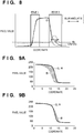
- Fig. 9A shows changes in signal level of image data of color components of red (R), green (G), and blue (B) in a portion in which chromatic aberration on the axis is generated.
- the correlation between the image data of the B color component and the image data of the G (or R) color component is lower than that between the image data of the R color component and the image data of the G color component. This is because the correlations between image data of a specific color component and image data of the remaining color components are lower in the portion in which chromatic aberration on the axis is generated than in the portion in which only magnification chromatic aberration is generated.
- the color phase of the edge portion may change before and after correction.
- Fig. 9B shows the state in which a correction amount is obtained using the sum total of the differences in signal level between the color components, and correction is performed using this correction amount, in the portion in which chromatic aberration on the axis is generated.
- a G plane serving as image data formed by a G color component and an R plane serving as image data formed by an R color component have no color deviation
- the G plane and a B plane serving as image data formed by a B color component have a color deviation, as shown in Fig. 9A .
- a region in which the difference in signal level between the B and G planes is large is present. For example, a portion corresponding to a hatched portion in Fig. 9A is in yellow, but a portion corresponding to a hatched portion in Fig.
- 9B is in another color, blue due to excessive correction, so the observer feels a great sense of discomfort upon a comparison between the color phases of the edge portion before and after correction.
- a method of relieving the observer's sense of discomfort by adjusting the color phase of the edge portion after correction is available, but it may deteriorate the original color structure of the object.
- the present invention has been made in consideration of the above-mentioned problem, and makes it possible to effectively correct magnification chromatic aberration by keeping the probability of excessive correction lower than the conventional methods in correcting chromatic aberration on the axis by image processing.
- the present invention provides an image processing apparatus as specified in claims 1 to 5.
- the present invention provides an image processing method as specified in claim 6.
- Fig. 1 is a block diagram showing an image processing apparatus according to an embodiment of the present invention
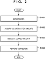
- Fig. 2 is a flowchart showing processing by the image processing apparatus according to the embodiment
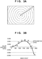
- Figs. 3A and 3B are views showing regions divided for each image height, and correction data
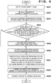
- Fig. 4 is a flowchart showing magnification chromatic aberration correction processing and on-axis chromatic aberration correction processing
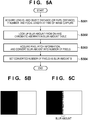
- Figs. 5A, 5B, and 5C are views illustrating an example of a method of setting the blur amount of chromatic aberration on the axis, a chart used to generate a blur, and a captured image;
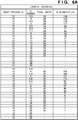
- Figs. 6A , 6B , and 6C are tables showing on-axis chromatic aberration information tables
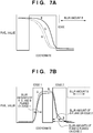
- Figs. 7A and 7B are graphs showing the relationships between edges and the blur amount
- Fig. 8 is a graph showing the relationship between the gradients of edges and the blur amount.
- Figs. 9A and 9B are graphs showing color deviations on edge portions.
- an image processing apparatus including an imaging system such as a digital camera is used in this embodiment, the present invention is applicable to image data which is formed by a plurality of color planes and is captured by the imaging system using an imaging lens such as a digital camera.
- a target image according to the present invention is limited to none of RAW data and JPEG data after development processing. It is also possible to practice the present invention using an image processing apparatus other than a digital camera after image data captured by, for example, a digital camera is read using the image processing apparatus. Therefore, an image processing apparatus according to the present invention need not always include an imaging lens.
- Fig. 1 is a block diagram showing an image processing apparatus according to an embodiment of the present invention.
- the image processing apparatus includes an imaging optical system 10, an image sensor 20, an A/D conversion unit 30, a color separation unit 40, an edge extraction unit 50 including an on-axis chromatic aberration edge extraction unit (on-axis chromatic aberration edge detection unit) 51, a magnification chromatic aberration correction data generation unit 60, a magnification chromatic aberration correction unit 70, an on-axis chromatic aberration correction unit 110, a control unit 80, a memory 90, and an I/F 100.
- an imaging optical system 10 an image sensor 20, an A/D conversion unit 30, a color separation unit 40
- an edge extraction unit 50 including an on-axis chromatic aberration edge extraction unit (on-axis chromatic aberration edge detection unit) 51, a magnification chromatic aberration correction data generation unit 60, a magnification chromatic aberration correction unit 70, an on-axis chromatic aberration correction unit 110
- the image sensor 20 is a single-plate color image sensor including a general primary color filter.
- the primary color filter includes three types of color filters having main pass bands around 650 nm, 550 nm, and 450 nm, and captures color planes corresponding to respective bands of R (Red), G (Green), and B (Blue) (generates image data formed by signals corresponding to a plurality of colors).
- R Red
- G Green
- B blue
- the A/D conversion unit 30 converts color mosaic image data output from the image sensor 20 as an analog voltage into digital data suitable for subsequent image processing.
- the color separation unit 40 interpolates the color mosaic image data to generate color image data having R, G, and B color information in all pixels.
- the edge extraction unit 50 including the on-axis chromatic aberration edge extraction unit 51 detects an edge (edge portion) from color image data generated by the color separation unit 40. Based on the detected edge information, the magnification chromatic aberration correction data generation unit 60 generates magnification chromatic aberration correction data from the image data. The magnification chromatic aberration correction unit 70 performs magnification chromatic aberration correction using the generated magnification chromatic aberration correction data. Image data used in each processing unit, and data such as capture time information are stored in the memory 90, and the control unit 80 controls this processing unit. Also, depending on circumstances involved, an external operation such as a user instruction is input to the image processing apparatus via the I/F (interface) 100.
- Fig. 2 is a flowchart showing a magnification chromatic aberration correction operation by the image processing apparatus according to this embodiment, and illustrates the sequence of processing by the edge extraction unit 50 including the on-axis chromatic aberration edge extraction unit 51, the correction data generation unit 60, and the correction unit 70.
- Magnification chromatic aberration correction by the image processing apparatus according to this embodiment will be explained below with reference to each step described in Fig. 2 .
- edges on each of which a color deviation due to magnification chromatic aberration conspicuously appears are detected from image data.
- the Y (luminance) plane is used for edge detection.
- edges to be detected are limited to edges on each of which the pixel value greatly changes outwards from a reference, which is assumed to be a position that coincides with the center of the optical axis on the image sensor, thereby acquiring accurate color deviation amounts.
- a color deviation due to magnification chromatic aberration appears as a blur, so an edge having a certain width so that a monotonic increase or monotonic decrease in signal level continues over a plurality of pixels is desirably targeted.
- color deviation amount acquisition step S102 a color deviation amount is acquired on each edge detected in edge detection step S101.
- color deviation amounts can typically be acquired using, for example, the above-mentioned method. This means that processing of moving the position of image data on one color plane relative to that of image data on another plane, and obtaining the sum total of the differences in signal level between the color components is repeatedly performed on each edge portion. The moving amount of the position of image data of one color component relative to that of image data of another color component when the sum total of the differences in signal level between the color components minimizes is obtained to obtain a correction amount so as to minimize the color deviation amount.
- the upward/downward direction, right/left direction, obliquely upward right/obliquely downward left direction, or obliquely upward left/obliquely downward right direction is adopted as the direction of a color deviation herein, for the sake of simple processing.
- the color deviation amount serving as an output in color deviation amount acquisition step S102 has a negative value when the R plane (or B plane) is shifted toward the optical center with respect to the G plane. However, this color deviation amount has a positive value when the R plane (or B plane) is shifted in a direction opposite to the optical center with respect to the G plane. In this case, in acquiring a color deviation amount, a method of measuring the degree of coincidence of each plane while this plane is shifted, and estimating a color deviation amount is adopted.
- correction data generation step S103 correction data is generated by obtaining the relationship between the image height and the color deviation based on the image height of each edge detected in edge detection step S101, and the color deviation amount on each edge acquired in color deviation amount acquisition step S102.
- the image height mentioned herein means the distance from the position (to be simply referred to as the optical center hereinafter) of a pixel located on the optical axis of the imaging lens to the pixel of interest.
- Image data is divided into eight regions h1 to h8 for each image height, as shown in Fig. 3A , to select a region to which each of the above-mentioned edges belongs.
- a high-order polynomial approximation equation F(1) representing the relationship between the image height and the color deviation ratio is calculated from the image height and the obtained color deviation ratio to determine the calculation result as correction data, as shown in Fig. 3B.
- Fig. 3B illustrates an example in which correction data is calculated using a third-order polynomial.
- edge detection and color deviation amount acquisition may be performed for all edges in the image data.
- the processing efficiency can be improved while maintaining a given reliability by, for example, ending edge detection and color deviation amount acquisition when color deviation ratios in a number equal to or larger than a predetermined threshold value are added up in each of the eight regions divided for each image height.
- correction data can be generated even if a region in which no corresponding edge is detected is present.
- correction step S104 the color deviation is corrected using the correction data generated in correction data generation step S103. That is, the color deviation is corrected by moving the position of image data of at least one of a plurality of color planes.
- the signal level of a pixel corresponding to the coordinate position (X1, Y1) on each plane to be corrected is generated by interpolation processing, in which the signal levels of surrounding pixels are added as weights, and is determined as the signal level of the pixel (X, Y). These operations are done for all pixels to perform color deviation correction.
- magnification chromatic aberration correction data is generated from an image, and the image is corrected has been described above.
- a Y plane signal is generated from R, G, and B plane signals generated by the color separation unit 40 first.
- Edge detection is performed for the Y plane defined in this equation. Although several edge detection methods are available, detection is done using the following method in this embodiment. Since an edge is a portion in which the signal level rapidly changes, differentiation in which a change in function is extracted can be used for edge detection.
- a first-order derivative gradient
- the edge intensity is calculated by: ⁇ fx 2 + fy 2 or fx + fy
- Image data obtained by performing edge detection on the Y plane using the above-mentioned method has a density corresponding to the edge intensity.
- a predetermined threshold value Th1 is set, and a pixel having a signal value larger than the threshold value Th1 is detected as an edge.
- a value according to which chromatic aberration can be detected as an edge need only be set.
- step S202 to detect chromatic aberration on the axis from each detected edge, a blur amount Th2 of the chromatic aberration on the axis is set. Step S202 will be described in detail with reference to Fig. 5A .
- chromatic aberration on the axis needs to be prepared in advance in the form of a table, and stored on the memory 90 shown in Fig. 1 .
- Chromatic aberration on the axis generates a blur in an amount which varies depending on various image capture conditions such as the type of lens, the object distance (or pupil distance), the F-number, and the focal length. Therefore, under various image capture conditions, charts are captured, and the generated blur amounts are measured.
- any chart may be captured, an edge having a monochrome chart with high contrast, as shown in, for example, Fig. 5B , can be used.
- Fig. 5C illustrates an example of the result of capturing the chart shown in Fig. 5B .
- a blur is naturally generated, as shown in Fig. 5C .
- the blur amount on that edge is measured.
- a list of the results of measuring the blur amounts while changing the image capture conditions in the same way is held as a table (table information) for each type of lens and each image capture condition, as shown in Figs. 6A-6C .
- step S301 the lens ID, the object distance (or pupil distance), the F-number at the time of image capture, the focal length, and the on-axis chromatic aberration blur amount table are acquired from the memory 90 shown in Fig. 1 .
- step S302 a blur amount corresponding to the image capture conditions is looked up from the on-axis chromatic aberration blur amount table. If the image capture conditions do not completely coincide with table data, a blur amount is obtained by interpolation calculation from approximate data.
- step S303 the obtained blur amount is divided by the pixel pitch to convert this blur amount into the number of pixels in which a blur is generated.
- step S304 the converted number of pixels having a blur is set as a blur amount Th2.
- a value which varies in each individual image capture condition is set as the blur amount Th2 serving as a threshold value.
- chromatic aberration evaluation is performed for an edge radially extending with reference to the optical center.
- Step S203 will be described in detail.
- Fig. 7A shows a detected edge, the R, G, and B planes on this edge, and the width of the set blur amount Th2.
- Monotonic increase/decrease determination is performed for a plane having a highest signal level (the B plane in this case) among the R, G, and B planes in this edge region.
- Chromatic aberration has a feature that its signal level gradually changes from a highlight portion to a shadow portion, that is, its signal level changes with a monotonic increase or a monotonic decrease.
- step S204 on-axis chromatic aberration evaluation is performed for the edge evaluated as an edge expected to include chromatic aberration.
- Signal level monotonic increase/decrease determination is performed for the R, G, and B planes in the edge region, and the blur amount on each plane is measured.
- the blur amount is the distance by which the signal level continuously changes with a monotonic increase or a monotonic decrease in successive pixels.
- Chromatic aberration on the axis is generated because one of the R, G, and B planes has a blur amount that is considerably different from those on the remaining planes.
- the detected edge is expected to be a normal edge or an edge including only magnification chromatic aberration at a high probability. Accordingly, an edge which satisfies the following two conditions is evaluated as an edge including chromatic aberration on the axis.
- At least one of the color planes which form the detected edge has a blur amount equal to or larger than the blur amount Th2 serving as a threshold value.
- At least another one of the color planes which form the detected edge has a blur amount smaller than the blur amount Th2 serving as a threshold value.
- edge 1 In an example shown in Fig. 7B , all of the R, G, and B planes on edge 1 have blur amounts smaller than the blur amount Th2, so edge 1 is evaluated as an edge expected to include no chromatic aberration on the axis at a high probability. Also, the R and G planes on edge 2 have blur amounts smaller than the blur amount Th2, and the B plane on edge 2 has a blur amount larger than the blur amount Th2, so edge 2 is evaluated as an edge expected to include chromatic aberration on the axis at a high probability. By the above-mentioned evaluation, the edge can be divided in accordance with the presence/absence of chromatic aberration on the axis.
- step S205 the edges detected in step S204 are excluded from the edge group detected in step S201, and edges which are not excluded are held as edges for color deviation amount acquisition.
- Edge detection step S101 has been described above. In this way, the color deviation amount acquisition accuracy can be improved not only by normal edge detection but also by excluding edges including chromatic aberration on the axis.
- step S206 a color deviation amount is acquired on each of the remaining edge portions.
- step S207 magnification chromatic aberration correction data representing the relationship between the image height and the color deviation amount is generated from the acquired color deviation amounts and the image heights of corresponding portions.
- step S208 magnification chromatic aberration is corrected using the magnification chromatic aberration correction data.
- step S209 the chromatic aberration on the axis is corrected.
- the signal level of a pixel in which chromatic aberration on the axis is generated need only be corrected so as to reduce the value of this color difference.
- the on-axis chromatic aberration edge extraction unit 51 has been described by taking, as an example, determination that the distance by which the signal level continuously changes with a monotonic increase or a monotonic decrease in successive pixels is defined as a blur amount, the present invention is not limited to this.
- GradRatioBG ⁇ B / ⁇ G
- ⁇ R and ⁇ G are calculated by similar calculation equations.
- the interval of pixels, in which the gradient ratio calculated in the above-mentioned equations continuously exceeds a threshold value Th3, is determined as a blur amount.
- Chromatic aberration on the axis is generated because one of the R, G, and B planes has a blur amount that is considerably different from those on the remaining planes.
- the detected edge is expected to be a normal edge or an edge including only magnification chromatic aberration at a high probability. Accordingly, an edge which satisfies the following two conditions is determined as an edge including chromatic aberration on the axis.
- At least one of the color planes which form the detected edge has a blur amount equal to or larger than the blur amount Th3 serving as a threshold value.
- At least another one of the color planes which form the detected edge has a blur amount smaller than the blur amount Th3 serving as a threshold value.
- edge 1 In an example shown in Fig. 8 , all of the R, G, and B planes on edge 1 have blur amounts smaller than the blur amount Th3, so edge 1 is evaluated as an edge expected to include no chromatic aberration on the axis at a high probability. Also, the R and G planes on edge 2 have blur amounts smaller than the blur amount Th3, and the B plane on edge 2 has a blur amount larger than the blur amount Th3, so edge 2 is evaluated as an edge expected to include chromatic aberration on the axis at a high probability.
- the edge can be divided in accordance with the presence/absence of chromatic aberration on the axis.
- aspects of the present invention can also be realized by a computer of a system or apparatus (or devices such as a CPU or MPU) that reads out and executes a program recorded on a memory device to perform the functions of the above-described embodiment(s), and by a method, the steps of which are performed by a computer of a system or apparatus by, for example, reading out and executing a program recorded on a memory device to perform the functions of the above-described embodiment(s).
- the program is provided to the computer for example via a network or from a recording medium of various types serving as the memory device (for example, computer-readable medium).
- An image processing apparatus comprises edge detection means (50) for detecting edges from image data, on-axis chromatic aberration edge detection means (51) for detecting an edge determined to include chromatic aberration on an axis from the edges, color deviation amount acquisition means (60) for acquiring color deviation amounts on the edges, and correction means (70) for performing chromatic aberration correction, wherein the on-axis chromatic aberration edge detection means detects, as the edge which includes the chromatic aberration on the axis, an edge having signals corresponding to at least one color on the edge of the image data, which has a blur amount that is not less than a threshold value, and signals corresponding to at least another color which has a blur amount that is less than the threshold value, and the color deviation amount acquisition means acquires the color
Landscapes
- Engineering & Computer Science (AREA)
- Multimedia (AREA)
- Signal Processing (AREA)
- Physics & Mathematics (AREA)
- General Physics & Mathematics (AREA)
- Theoretical Computer Science (AREA)
- Computer Vision & Pattern Recognition (AREA)
- Image Processing (AREA)
- Color Television Image Signal Generators (AREA)
Applications Claiming Priority (2)
| Application Number | Priority Date | Filing Date | Title |
|---|---|---|---|
| JP2011035177 | 2011-02-21 | ||
| JP2012013430A JP5840008B2 (ja) | 2011-02-21 | 2012-01-25 | 画像処理装置、画像処理方法およびプログラム |
Publications (2)
| Publication Number | Publication Date |
|---|---|
| EP2490174A2 true EP2490174A2 (de) | 2012-08-22 |
| EP2490174A3 EP2490174A3 (de) | 2017-11-22 |
Family
ID=45592255
Family Applications (1)
| Application Number | Title | Priority Date | Filing Date |
|---|---|---|---|
| EP12155775.5A Withdrawn EP2490174A3 (de) | 2011-02-21 | 2012-02-16 | Bildverarbeitungsvorrichtung, Bildverarbeitungsverfahren und Programm |
Country Status (5)
| Country | Link |
|---|---|
| US (1) | US8736737B2 (de) |
| EP (1) | EP2490174A3 (de) |
| JP (1) | JP5840008B2 (de) |
| KR (1) | KR101368715B1 (de) |
| CN (1) | CN102685511B (de) |
Cited By (3)
| Publication number | Priority date | Publication date | Assignee | Title |
|---|---|---|---|---|
| EP2860974A1 (de) * | 2013-10-08 | 2015-04-15 | Canon Kabushiki Kaisha | Bildverarbeitungsvorrichtung, Bildaufnahmevorrichtung, Bildaufnahmesystem, Bildverarbeitungsverfahren, Bildverarbeitungsprogramm und Speichermedium |
| US9563941B2 (en) | 2013-10-09 | 2017-02-07 | Canon Kabushiki Kaisha | Image processing apparatus, image pickup apparatus, image processing method, and non-transitory computer-readable storage medium |
| US10659738B2 (en) | 2015-05-12 | 2020-05-19 | Olympus Corporation | Image processing apparatus, image processing method, and image processing program product |
Families Citing this family (11)
| Publication number | Priority date | Publication date | Assignee | Title |
|---|---|---|---|---|
| JP5367053B2 (ja) * | 2011-02-28 | 2013-12-11 | キヤノン株式会社 | 画像処理装置、画像処理プログラム、画像処理方法及び撮像装置 |
| CN103514585B (zh) | 2013-09-12 | 2016-03-02 | 深圳市华星光电技术有限公司 | 一种图像处理方法 |
| JP6415108B2 (ja) * | 2014-05-22 | 2018-10-31 | キヤノン株式会社 | 画像処理方法、画像処理装置、撮像装置、画像処理プログラム、および、記憶媒体 |
| JP6238673B2 (ja) * | 2013-10-08 | 2017-11-29 | キヤノン株式会社 | 画像処理装置、撮像装置、撮像システム、画像処理方法、画像処理プログラム、および、記憶媒体 |
| TWI594632B (zh) | 2013-12-31 | 2017-08-01 | 佳能企業股份有限公司 | 一種影像補正參數的設定方法、電子裝置、電子裝置可讀取的儲存媒體與應用於電子裝置的程式 |
| CN104767982A (zh) * | 2014-01-03 | 2015-07-08 | 佳能企业股份有限公司 | 一种影像补正参数的设定方法与电子装置 |
| JP6604737B2 (ja) * | 2015-04-07 | 2019-11-13 | キヤノン株式会社 | 画像処理装置、撮像装置、画像処理方法、画像処理プログラム、および、記憶媒体 |
| US10735754B2 (en) * | 2017-04-26 | 2020-08-04 | Google Llc | Chromatic aberration modeling in image compression and enhancement |
| JP7051580B2 (ja) * | 2018-05-21 | 2022-04-11 | キヤノン株式会社 | 画像処理装置、撮像装置、画像処理方法および画像処理プログラム |
| US11350063B2 (en) * | 2020-04-14 | 2022-05-31 | Apple Inc. | Circuit for correcting lateral chromatic abberation |
| CN114581380B (zh) * | 2022-02-16 | 2024-08-20 | 合肥埃科光电科技股份有限公司 | 一种基于fpga的色散矫正方法及存储介质 |
Citations (2)
| Publication number | Priority date | Publication date | Assignee | Title |
|---|---|---|---|---|
| JP2000299874A (ja) | 1999-04-12 | 2000-10-24 | Sony Corp | 信号処理装置及び方法並びに撮像装置及び方法 |
| JP2006020275A (ja) | 2004-05-31 | 2006-01-19 | Nikon Corp | Rawデータから倍率色収差を検出する画像処理装置、画像処理プログラム、および電子カメラ |
Family Cites Families (13)
| Publication number | Priority date | Publication date | Assignee | Title |
|---|---|---|---|---|
| JP3925588B2 (ja) * | 1997-11-25 | 2007-06-06 | セイコーエプソン株式会社 | 画像処理装置、画像処理方法および画像処理制御プログラムを記録した媒体 |
| KR20040009966A (ko) | 2002-07-26 | 2004-01-31 | 삼성전자주식회사 | 색 보정장치 및 방법 |
| JP2004120487A (ja) * | 2002-09-27 | 2004-04-15 | Fuji Photo Film Co Ltd | 撮像装置 |
| JP2005236770A (ja) | 2004-02-20 | 2005-09-02 | Mitsubishi Electric Corp | 画素補間回路、画像読取装置、および画素補間方法 |
| JP4945942B2 (ja) * | 2005-07-14 | 2012-06-06 | 株式会社ニコン | 画像処理装置 |
| WO2007088965A1 (ja) | 2006-02-03 | 2007-08-09 | Nikon Corporation | 画像処理装置、画像処理方法、および画像処理プログラム |
| WO2007105359A1 (ja) * | 2006-03-01 | 2007-09-20 | Nikon Corporation | 倍率色収差を画像解析する画像処理装置、画像処理プログラム、電子カメラ、および画像処理方法 |
| KR100866490B1 (ko) * | 2007-01-17 | 2008-11-03 | 삼성전자주식회사 | 영상의 색 수차를 보정하기 위한 장치 및 방법 |
| JP2009105579A (ja) | 2007-10-22 | 2009-05-14 | Sony Corp | 色信号処理回路、撮像装置及び色信号処理方法 |
| JP5132401B2 (ja) * | 2008-04-16 | 2013-01-30 | キヤノン株式会社 | 画像処理装置及び画像処理方法 |
| JP5047048B2 (ja) * | 2008-04-30 | 2012-10-10 | キヤノン株式会社 | 画像処理装置、撮像装置、制御方法、プログラム、及び記憶媒体 |
| JP4730412B2 (ja) * | 2008-08-12 | 2011-07-20 | ソニー株式会社 | 画像処理装置及び画像処理方法 |
| JP2010219683A (ja) * | 2009-03-13 | 2010-09-30 | Sony Corp | 画像処理装置、画像処理方法及びプログラム |
-
2012
- 2012-01-25 JP JP2012013430A patent/JP5840008B2/ja not_active Expired - Fee Related
- 2012-02-07 US US13/368,052 patent/US8736737B2/en not_active Expired - Fee Related
- 2012-02-16 KR KR1020120015659A patent/KR101368715B1/ko not_active Expired - Fee Related
- 2012-02-16 EP EP12155775.5A patent/EP2490174A3/de not_active Withdrawn
- 2012-02-21 CN CN201210041459.7A patent/CN102685511B/zh not_active Expired - Fee Related
Patent Citations (2)
| Publication number | Priority date | Publication date | Assignee | Title |
|---|---|---|---|---|
| JP2000299874A (ja) | 1999-04-12 | 2000-10-24 | Sony Corp | 信号処理装置及び方法並びに撮像装置及び方法 |
| JP2006020275A (ja) | 2004-05-31 | 2006-01-19 | Nikon Corp | Rawデータから倍率色収差を検出する画像処理装置、画像処理プログラム、および電子カメラ |
Non-Patent Citations (1)
| Title |
|---|
| E.CHANG; S.CHEUNG; D.PAN: "Color filter array recovery using a threshold-based variable number of gradients", PROC. SPIE, vol. 3650, January 1999 (1999-01-01), pages 36 - 43, XP002310496, DOI: doi:10.1117/12.342861 |
Cited By (5)
| Publication number | Priority date | Publication date | Assignee | Title |
|---|---|---|---|---|
| EP2860974A1 (de) * | 2013-10-08 | 2015-04-15 | Canon Kabushiki Kaisha | Bildverarbeitungsvorrichtung, Bildaufnahmevorrichtung, Bildaufnahmesystem, Bildverarbeitungsverfahren, Bildverarbeitungsprogramm und Speichermedium |
| US9438771B2 (en) | 2013-10-08 | 2016-09-06 | Canon Kabushiki Kaisha | Image processing apparatus, image pickup apparatus, image pickup system, image processing method, and non-transitory computer-readable storage medium |
| US9563941B2 (en) | 2013-10-09 | 2017-02-07 | Canon Kabushiki Kaisha | Image processing apparatus, image pickup apparatus, image processing method, and non-transitory computer-readable storage medium |
| US9747672B2 (en) | 2013-10-09 | 2017-08-29 | Canon Kabushiki Kaisha | Image processing apparatus, image pickup apparatus, image processing method, and non-transitory computer-readable storage medium |
| US10659738B2 (en) | 2015-05-12 | 2020-05-19 | Olympus Corporation | Image processing apparatus, image processing method, and image processing program product |
Also Published As
| Publication number | Publication date |
|---|---|
| US20120212644A1 (en) | 2012-08-23 |
| EP2490174A3 (de) | 2017-11-22 |
| JP2012191607A (ja) | 2012-10-04 |
| JP5840008B2 (ja) | 2016-01-06 |
| KR101368715B1 (ko) | 2014-03-04 |
| CN102685511A (zh) | 2012-09-19 |
| KR20120095791A (ko) | 2012-08-29 |
| CN102685511B (zh) | 2014-09-03 |
| US8736737B2 (en) | 2014-05-27 |
Similar Documents
| Publication | Publication Date | Title |
|---|---|---|
| US8736737B2 (en) | Image processing apparatus, image processing method, and storage medium | |
| EP1528797B1 (de) | Bildverarbeitungsvorrichtung, Bildaufnahmesystem und Bildverarbeitungsverfahren | |
| US8587712B2 (en) | Image processing apparatus and method of correcting image quality degradation caused by aberrations due to optical system | |
| US10582180B2 (en) | Depth imaging correction apparatus, imaging apparatus, and depth image correction method | |
| EP1746846A1 (de) | Bildverarbeitungseinrichtung mit farbverschiebungskorrekturfunktion, bildverarbeitungsprogramm und elektronische kamera | |
| JP6074954B2 (ja) | 合焦評価装置、撮像装置およびプログラム | |
| EP2785047B1 (de) | Bildaufnahmevorrichtung, Bildverarbeitungssystem, Bildverarbeitungsverfahren, Bildverarbeitungsprogramm und Speichermedium | |
| US8774551B2 (en) | Image processing apparatus and image processing method for reducing noise | |
| US8542920B2 (en) | Image processing apparatus, image processing method, and program | |
| EP3015892A1 (de) | Vorrichtung und verfahren zur bildaufnahme | |
| EP3276955A1 (de) | Bildverarbeitungsvorrichtung, bildverarbeitungsverfahren und bildverarbeitungsprogramm | |
| JP6066866B2 (ja) | 画像処理装置、その制御方法、および制御プログラム | |
| US9118878B2 (en) | Image processing apparatus that corrects for chromatic aberration for taken image, image pickup apparatus, method of correcting for chromatic aberration of magnification therefor, and storage medium | |
| US20150161771A1 (en) | Image processing method, image processing apparatus, image capturing apparatus and non-transitory computer-readable storage medium | |
| US20110187887A1 (en) | Image processing apparatus, image pickup apparatus and image processing program for correcting color blur | |
| EP3276944B1 (de) | Bildverarbeitungsvorrichtung, bilderfassungsvorrichtung, bildverarbeitungsverfahren und bildverarbeitungsprogramm | |
| JP6089476B2 (ja) | 画像処理装置、撮像装置、および画像処理プログラム | |
| US8457393B2 (en) | Cross-color image processing systems and methods for sharpness enhancement | |
| JP2018088587A (ja) | 画像処理方法および画像処理装置 | |
| JP5147577B2 (ja) | 画像処理装置およびその方法 | |
| JP7051580B2 (ja) | 画像処理装置、撮像装置、画像処理方法および画像処理プログラム | |
| JP2017116606A (ja) | 焦点調節装置、撮像装置およびプログラム |
Legal Events
| Date | Code | Title | Description |
|---|---|---|---|
| PUAI | Public reference made under article 153(3) epc to a published international application that has entered the european phase |
Free format text: ORIGINAL CODE: 0009012 |
|
| AK | Designated contracting states |
Kind code of ref document: A2 Designated state(s): AL AT BE BG CH CY CZ DE DK EE ES FI FR GB GR HR HU IE IS IT LI LT LU LV MC MK MT NL NO PL PT RO RS SE SI SK SM TR |
|
| AX | Request for extension of the european patent |
Extension state: BA ME |
|
| PUAL | Search report despatched |
Free format text: ORIGINAL CODE: 0009013 |
|
| AK | Designated contracting states |
Kind code of ref document: A3 Designated state(s): AL AT BE BG CH CY CZ DE DK EE ES FI FR GB GR HR HU IE IS IT LI LT LU LV MC MK MT NL NO PL PT RO RS SE SI SK SM TR |
|
| AX | Request for extension of the european patent |
Extension state: BA ME |
|
| RIC1 | Information provided on ipc code assigned before grant |
Ipc: G06T 5/00 20060101AFI20171016BHEP Ipc: G06T 7/00 20170101ALI20171016BHEP Ipc: H04N 9/04 20060101ALI20171016BHEP |
|
| STAA | Information on the status of an ep patent application or granted ep patent |
Free format text: STATUS: THE APPLICATION HAS BEEN WITHDRAWN |
|
| 18W | Application withdrawn |
Effective date: 20180130 |