EP2489271A2 - Dispositif destiné au traitement de pâte - Google Patents
Dispositif destiné au traitement de pâte Download PDFInfo
- Publication number
- EP2489271A2 EP2489271A2 EP12155483A EP12155483A EP2489271A2 EP 2489271 A2 EP2489271 A2 EP 2489271A2 EP 12155483 A EP12155483 A EP 12155483A EP 12155483 A EP12155483 A EP 12155483A EP 2489271 A2 EP2489271 A2 EP 2489271A2
- Authority
- EP
- European Patent Office
- Prior art keywords
- tub
- clamping
- dough
- processing
- counter
- Prior art date
- Legal status (The legal status is an assumption and is not a legal conclusion. Google has not performed a legal analysis and makes no representation as to the accuracy of the status listed.)
- Granted
Links
Images


Classifications
-
- A—HUMAN NECESSITIES
- A21—BAKING; EDIBLE DOUGHS
- A21C—MACHINES OR EQUIPMENT FOR MAKING OR PROCESSING DOUGHS; HANDLING BAKED ARTICLES MADE FROM DOUGH
- A21C1/00—Mixing or kneading machines for the preparation of dough
- A21C1/02—Mixing or kneading machines for the preparation of dough with vertically-mounted tools; Machines for whipping or beating
-
- A—HUMAN NECESSITIES
- A21—BAKING; EDIBLE DOUGHS
- A21C—MACHINES OR EQUIPMENT FOR MAKING OR PROCESSING DOUGHS; HANDLING BAKED ARTICLES MADE FROM DOUGH
- A21C1/00—Mixing or kneading machines for the preparation of dough
- A21C1/14—Structural elements of mixing or kneading machines; Parts; Accessories
- A21C1/149—Receptacles, e.g. provided with means for carrying or guiding fluids, e.g. coolants
-
- B—PERFORMING OPERATIONS; TRANSPORTING
- B01—PHYSICAL OR CHEMICAL PROCESSES OR APPARATUS IN GENERAL
- B01F—MIXING, e.g. DISSOLVING, EMULSIFYING OR DISPERSING
- B01F27/00—Mixers with rotary stirring devices in fixed receptacles; Kneaders
- B01F27/80—Mixers with rotary stirring devices in fixed receptacles; Kneaders with stirrers rotating about a substantially vertical axis
- B01F27/805—Mixers with rotary stirring devices in fixed receptacles; Kneaders with stirrers rotating about a substantially vertical axis wherein the stirrers or the receptacles are moved in order to bring them into operative position; Means for fixing the receptacle
- B01F27/806—Mixers with rotary stirring devices in fixed receptacles; Kneaders with stirrers rotating about a substantially vertical axis wherein the stirrers or the receptacles are moved in order to bring them into operative position; Means for fixing the receptacle with vertical displacement of the stirrer, e.g. in combination with means for pivoting the stirrer about a vertical axis in order to co-operate with different receptacles
-
- B—PERFORMING OPERATIONS; TRANSPORTING
- B01—PHYSICAL OR CHEMICAL PROCESSES OR APPARATUS IN GENERAL
- B01F—MIXING, e.g. DISSOLVING, EMULSIFYING OR DISPERSING
- B01F33/00—Other mixers; Mixing plants; Combinations of mixers
- B01F33/80—Mixing plants; Combinations of mixers
- B01F33/85—Mixing plants with mixing receptacles or mixing tools that can be indexed into different working positions
-
- B—PERFORMING OPERATIONS; TRANSPORTING
- B01—PHYSICAL OR CHEMICAL PROCESSES OR APPARATUS IN GENERAL
- B01F—MIXING, e.g. DISSOLVING, EMULSIFYING OR DISPERSING
- B01F35/00—Accessories for mixers; Auxiliary operations or auxiliary devices; Parts or details of general application
- B01F35/40—Mounting or supporting mixing devices or receptacles; Clamping or holding arrangements therefor
- B01F35/42—Clamping or holding arrangements for mounting receptacles on mixing devices
-
- B—PERFORMING OPERATIONS; TRANSPORTING
- B01—PHYSICAL OR CHEMICAL PROCESSES OR APPARATUS IN GENERAL
- B01F—MIXING, e.g. DISSOLVING, EMULSIFYING OR DISPERSING
- B01F35/00—Accessories for mixers; Auxiliary operations or auxiliary devices; Parts or details of general application
- B01F35/50—Mixing receptacles
Definitions
- the invention relates to a device for processing dough. Furthermore, the invention relates to a dough tub for use in such a processing device and a processing carousel with at least two such dough processing devices and at least one such dough tub.
- Processing devices for dough are known from the DE 198 20 272 C2 , of the DE 689 03 071 T2 and the DE 603 04 657 T2 , Further mixers are known from the DE 600 06 433 T2 and the DE 60 2004 008 152 T2 , From the DE-PS 296 789 a device is known on dough kneading machines for releasably attaching a rotatable tub to a machine frame.
- a holding device with an axial clamping thus acting along the vertical axis of the tub, leads to the possibility of forming a clamping stroke between a clamping position and a release position of the holding device with little distance.
- the clamping force exerted by the clamping punch on the counter-clamping body acts in the axial direction.
- the switching to the clamping position and thus the fixing of the dough tub in a processing position can then be done very quickly. Changeover times in the range of a few seconds, for example in the Range of 2 s, are possible. Idle times in which the dough can not be processed are reduced accordingly.
- a drive of the clamping punch according to claim 2 allows automated operation of the holding device.
- the clamping punch can be hydraulically driven and cooperate with a lifting cylinder and a reciprocating piston.
- Another drive for example a pneumatic or an electromechanical drive, for the clamping punch is possible.
- a profiled embodiment of the clamping punch according to claim 3 improves the clamping action of the clamping punch.
- the profiling of the clamping punch can cooperate with a preferably complementary running counter profiling of the tub clamp foot. In this way, an exact positioning of the dough tub in the processing position can be achieved.
- a two-part embodiment of the counter-clamping body according to claim 4 leads to a particularly secure clamping.
- a processing device with a carousel drive and a counter-clamping body with two clamping rails leads to the possibility of integration of the processing device in a processing carousel with a plurality of processing stations, wherein a secure clamping of the dough tub is given in the processing position.
- the arc shape of the displacement direction can coincide exactly with the arc shape of the gap between the clamping rails. This leads to the possibility of a gap between the tub clamp foot and the two clamping rails in the radial direction of this arch shape to minimize, so that a positionally secure clamping results.
- the clamping rails can also accomplish a guide of the tub relocation in the processing position.
- a processing carousel can also be designed with a central carousel drive, so that the individual processing devices of the processing carousel do not have their own carousel drive.
- a rotatable tub clamp foot according to claim 7 allows with clamped tub clamp foot twisting the tub container around the tub axis, which is advantageous for dough processing.
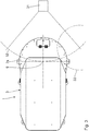
- a processing apparatus 1 for processing and in particular for mixing and kneading dough has a support frame 2 within a machine housing 3 with a stand 4 and an arm 5, which is also referred to as a head.
- a tub 6 of the processing device 1 serves to receive the dough to be kneaded and mixed.
- the tub 6 is in perspective in the Fig. 7 shown.
- a kneading tool 7 in the form of a vertical double kneading spiral.
- the processing device 1 is thus a Doppelwerkmaschinemaschinemaschinekneter with two kneading spirals.
- the kneading tool 7 is in the Fig. 1 shown in a rest position in which the kneading tool 7 is completely pulled out of the dough tub 6 in the vertical direction.
- the kneading tool 7 protrudes in a working position, which in the FIG. 1 is not shown, starting from a projecting beyond the stand 4 head portion 8 of the arm 5 from above into the tub 6 into it.
- Part of the kneading tool 7 is a cover 7a, which covers the dough tub 6 in the working position of the kneading tool 7 upwards.
- the cover 7a represents a flour dust cover.
- a guide body 10 of the kneading tool 7 for guiding a movement of the dough in the tub 6 is arranged in the region of the vertical axis 9. Between the guide body 10 and the rest zone can form a vertically extending air column within the tub 6 during operation of the processing device 1.
- the tub 6 is rotated in the operation of the processing device 1 by a motor in a conventional manner about the vertical axis 9. This is done via a friction wheel, which is pivoted away from the tub 6 in a rest position.
- the kneading tool 7 is driven by a central, also vertically extending Knetspiralachse 11, which is parallel spaced from the vertical axis 9, driven by a motor.
- This kneading drive is housed in the lid 7 a of the kneading tool 7.
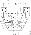
- the processing device 1 has a holding device 12 for releasably holding the dough tub 6.
- This holding device 12 which is also referred to as a boiler receptacle, is in total in the 4 to 6 shown.
- a base frame plate 14 of the holding device 12 is screwed to the support frame 2 of the processing device 1.
- the holding device 12 has a clamping punch 15 for engagement with a bottom 16 of a bottom side on the dough tub 6 mounted tub clamp foot 17.
- This investment of the clamping punch 15 at the tub clamp foot 17 takes place with a clamping force in the axial direction along the tub axis 9.
- a contact wall 18 of the clamping punch 15 is designed to bear against the bottom 16 of the tub clamp foot 17 profiled.
- This profiling is designed as around the investment wall 18 outside circumferential, raised clamping ring 19.
- the underside 16 of the tub clamp foot 17 of the tub 6 is formed with a counter-profiling complementary to this profiling of the abutment wall 18.
- This counter profiling has a complementary to the clamping ring 19 configured circumferential recess 20.
- the clamping punch 15 is axially displaceable relative to the base frame plate 14 and relative to a stationary with respect to the base frame plate 14 counter-clamping body 21 displaced.
- the holding device 12 has a hydraulic lifting cylinder 22, which is arranged below the clamping punch 15 and fixed to the base frame plate 14.
- a reciprocating piston 23 whose free end is screwed to the clamping punch 15 is running.
- an axial drive for the clamping punch 15 can also be realized by a different type of drive.
- the counter-clamping body 21 of the holding device 12 is used for engaging behind the tub clamp foot 17 between the tub clamp foot 17 and a tub container 24 of the dough tub 6.
- the counter-clamping body 21 is made in two parts and has two clamping rails 25, 26, between which an arcuate gap 27 is present.
- the two clamping rails 25, 26 are welded via spacer carrier 28 with the base frame plate 14.
- the two clamping rails 25, 26 engage behind the tub 27 arranged in the intermediate space clamp foot 17 on both sides.
- the tub clamp foot 17 of the dough tub 6 is rotatably mounted on the tub vertical axis 9 on the tub container 24.
- the latter is an axial / radial bearing.
- the ball bearing 29 forms a trailing engagement, which engages behind a bottom of the tub container 24 circumferential collar 30 of the tub clamp foot 17. With fixed tub clamp foot 17, the tub container 24 can thus rotate about the tub axis 9.
- the processing device 1 can be part of a processing carousel with several processing stations for dough processing. These other processing stations are not shown.
- To move the Teigbottichs 6 in a matching with the clamping position processing position of Teigbottichs 6 for processing the dough by the processing device 1 and the displacement of the Teigbottichs 6 from the processing position to another position for processing by another processing device or processing station of the carousel is used in of the Fig. 3 schematically indicated carousel drive 31, which is arranged in the region of a central axis of rotation of the carousel.
- the tub clamp foot 17 is arranged for clamping relative to the holding device 12 as in FIGS Fig. 1 and 2 shown.
- a displacement of the dough tub 6 by the carousel drive 31 along an arcuate path 32 (see. Fig. 3 ).
- the carousel drive 31 is thus designed so that a direction of displacement of the dough tub 6 by the carousel drive 31 in the region of the processing position is arcuate.
- the arcuate shape of the gap 27 between the two clamping rails 25, 26 corresponds to this arcuate shape of the web 32.
- the tub clamp foot 17 can therefore be moved during movement along the track 32 with a very small distance between the two clamping rails 25, 26 therethrough.
- the dough in the dough tub 6 is first prepared for kneading and mixing in the processing device 1 upstream processing station. Subsequently, the dough tub 6 is displaced along the path 32 into the processing position, in which a rotational axis of symmetry of the clamping punch 15 is aligned with the tub axis 9. An intermediate position of the dough tub 6 on the displacement path to the processing position is in the Fig. 3 indicated by dashed lines at 33.
- the holding device 12 When moving to the processing position, the holding device 12 is initially in a release position, in which the lifting piston 23 is retracted into the lifting cylinder 22. In this release position is in the axial direction between the clamping die 15 and the counter-clamping body 21, so the two clamping rails 25, 26 before a gap, which is so large that the tub clamp foot 17 along the path 32 from the side in the Holding device 12 can be retracted.
- the lifting cylinder 22 is acted upon and the lifting piston 23 extended, so that the holding device 12, the clamping position, in the Fig. 2 shown is achieved.
- a changeover of the lifting piston 23 from the release position into the clamping position takes about 2 s.
- the clamping punch is arranged stationary to the base frame plate 14 and the counter-clamping body, formed in particular by the two clamping rails, is axially driven to reach the clamping position on the clamping punch 15 to move.
- the counter-clamping body 21 may also be made in one piece in an embodiment of the processing device, not shown. For example, it can be clamped radially outside or radially inside the web 32.
- the perspective view of the tub clamp foot 17 after Fig. 7 shows that this is not rotationally symmetrical.
- the clamping foot 17 has two outer inclined surfaces 34 in the region of two opposite circumferential positions. These cooperate with complementary inclined surfaces 35 on the underside of the clamping rails 25, 26 in the clamping position (cf. Fig. 2 ).
- Fig. 7 further shows a rotatably mounted with the tub clamp foot 17 mounting frame 36, which serves to transport the tub 6 in the processing carousel.
- the bearing 29 of the tub container 24 can be rotated relative to the support frame 36 about the vertical axis 9, in particular in the kneading operation.
Landscapes
- Chemical & Material Sciences (AREA)
- Chemical Kinetics & Catalysis (AREA)
- Life Sciences & Earth Sciences (AREA)
- Engineering & Computer Science (AREA)
- Food Science & Technology (AREA)
- Manufacturing And Processing Devices For Dough (AREA)
Applications Claiming Priority (1)
| Application Number | Priority Date | Filing Date | Title |
|---|---|---|---|
| DE102011004433A DE102011004433A1 (de) | 2011-02-21 | 2011-02-21 | Vorrichtung zum Bearbeiten von Teig |
Publications (3)
| Publication Number | Publication Date |
|---|---|
| EP2489271A2 true EP2489271A2 (fr) | 2012-08-22 |
| EP2489271A3 EP2489271A3 (fr) | 2013-04-17 |
| EP2489271B1 EP2489271B1 (fr) | 2016-07-20 |
Family
ID=45655779
Family Applications (1)
| Application Number | Title | Priority Date | Filing Date |
|---|---|---|---|
| EP12155483.6A Not-in-force EP2489271B1 (fr) | 2011-02-21 | 2012-02-15 | Dispositif destiné au traitement de pâte |
Country Status (2)
| Country | Link |
|---|---|
| EP (1) | EP2489271B1 (fr) |
| DE (1) | DE102011004433A1 (fr) |
Cited By (2)
| Publication number | Priority date | Publication date | Assignee | Title |
|---|---|---|---|---|
| CN107185435A (zh) * | 2017-07-18 | 2017-09-22 | 深圳市江途机械科技有限公司 | 一种环保涂料装置 |
| CN110170267A (zh) * | 2019-06-06 | 2019-08-27 | 上海外高桥造船有限公司 | 一种无机硅酸锌底漆自动搅拌装置 |
Citations (6)
| Publication number | Priority date | Publication date | Assignee | Title |
|---|---|---|---|---|
| DE296789C (fr) | ||||
| DE68903071T2 (de) | 1988-07-05 | 1993-02-18 | Sancassiano Spa | Knetmaschine fuer nahrungsprodukte, insbesondere mehlgemische. |
| DE19820272C2 (de) | 1998-05-07 | 2002-10-31 | Diosna Dierks & Soehne Gmbh | Anlage zur Teigbereitung für Backwaren |
| DE60006433T2 (de) | 1999-02-10 | 2004-09-09 | Vmi | Befestigungsanordnung eines Gitters für eine Mischvorrichtung |
| DE60304657T2 (de) | 2002-11-26 | 2006-08-31 | Sancassiano S.P.A., Roddi D'alba | Knetmaschine für Teigmittel, insbesondere für Backwaren |
| DE602004008152T2 (de) | 2003-06-17 | 2008-05-08 | Vmi | System für das elastische Halten eines Behälters in Bezug auf einen Mischkopf eines Mischers |
Family Cites Families (5)
| Publication number | Priority date | Publication date | Assignee | Title |
|---|---|---|---|---|
| US2791405A (en) * | 1954-05-24 | 1957-05-07 | Liston Sol | Continuous automatic dough making means |
| US3877683A (en) * | 1974-03-22 | 1975-04-15 | Scm Corp | Batch tinting apparatus |
| IT1165694B (it) * | 1979-07-23 | 1987-04-22 | Costa Rinaldo | Macchina impastatrice in particolare utile per prodotti alimentari |
| IT1155169B (it) * | 1982-04-27 | 1987-01-21 | Rinaldo Costa | Macchina impastatrice di prodotti alimentari |
| SE431152B (sv) * | 1983-04-06 | 1984-01-23 | Glimek Ab | Anordning for fixering av blandningskerl till blandare |
-
2011
- 2011-02-21 DE DE102011004433A patent/DE102011004433A1/de not_active Ceased
-
2012
- 2012-02-15 EP EP12155483.6A patent/EP2489271B1/fr not_active Not-in-force
Patent Citations (6)
| Publication number | Priority date | Publication date | Assignee | Title |
|---|---|---|---|---|
| DE296789C (fr) | ||||
| DE68903071T2 (de) | 1988-07-05 | 1993-02-18 | Sancassiano Spa | Knetmaschine fuer nahrungsprodukte, insbesondere mehlgemische. |
| DE19820272C2 (de) | 1998-05-07 | 2002-10-31 | Diosna Dierks & Soehne Gmbh | Anlage zur Teigbereitung für Backwaren |
| DE60006433T2 (de) | 1999-02-10 | 2004-09-09 | Vmi | Befestigungsanordnung eines Gitters für eine Mischvorrichtung |
| DE60304657T2 (de) | 2002-11-26 | 2006-08-31 | Sancassiano S.P.A., Roddi D'alba | Knetmaschine für Teigmittel, insbesondere für Backwaren |
| DE602004008152T2 (de) | 2003-06-17 | 2008-05-08 | Vmi | System für das elastische Halten eines Behälters in Bezug auf einen Mischkopf eines Mischers |
Cited By (3)
| Publication number | Priority date | Publication date | Assignee | Title |
|---|---|---|---|---|
| CN107185435A (zh) * | 2017-07-18 | 2017-09-22 | 深圳市江途机械科技有限公司 | 一种环保涂料装置 |
| CN107185435B (zh) * | 2017-07-18 | 2018-11-02 | 台州云造智能科技有限公司 | 一种环保涂料装置 |
| CN110170267A (zh) * | 2019-06-06 | 2019-08-27 | 上海外高桥造船有限公司 | 一种无机硅酸锌底漆自动搅拌装置 |
Also Published As
| Publication number | Publication date |
|---|---|
| EP2489271A3 (fr) | 2013-04-17 |
| DE102011004433A1 (de) | 2012-08-23 |
| EP2489271B1 (fr) | 2016-07-20 |
Similar Documents
| Publication | Publication Date | Title |
|---|---|---|
| EP2208549B1 (fr) | Outil de cintrage rotatif à traction avec bridage excentrique | |
| DE60129375T2 (de) | Reifenabdrückvorrichtung für ein Raddemontiergerät, und Raddemontiergerät mit einer solchen Vorrichtung | |
| DE2760355C2 (fr) | ||
| EP2036629A1 (fr) | Procédé et dispositif de coupe fine et de formage d'une pièce à usiner | |
| CH657567A5 (de) | Revolver-stanze. | |
| EP3450042B1 (fr) | Outil multiple | |
| WO2017220393A1 (fr) | Dispositif pour calibrer et dresser des pièces creuses et procédé à mettre en œuvre avec un dispositif de ce type | |
| DE102007057790B4 (de) | Rundlaufpresse | |
| DE102008006045B4 (de) | Tablettenpresse | |
| DE2314858A1 (de) | Einrichtung zum bearbeiten von metallischen werkstuecken | |
| EP2489271B1 (fr) | Dispositif destiné au traitement de pâte | |
| EP3201072A1 (fr) | Dispositif de permutation pour modules de serrage ou de centrage | |
| EP2873512A1 (fr) | Procédé et dispositif d'estampillage et de liaison de pièces en matière plastique | |
| DE2527248A1 (de) | Stanzeinheit | |
| WO1999037419A1 (fr) | Dispositif de sertissage a elements de pression et de serrage | |
| DE3908582C2 (fr) | ||
| EP3025802A1 (fr) | Dispositif et procédé pour le fluotournage de pièces à usiner | |
| DE3045089A1 (de) | Kreisschere | |
| DE3727817A1 (de) | Montagevorrichtung fuer mindestens einen reifen | |
| DE19811418B4 (de) | Spannzange für eine Schneidmaschine | |
| DE102012004605B4 (de) | Verfahren und Werkzeug zur spanenden Bearbeitung von Lagerstellen in einem Bremssattel | |
| DE754923C (de) | Vorrichtung zum selbsttaetigen Herstellen und Einschlagen von Heftklammern in fortlaufend bewegte, von Zylindern getragene Werkstuecke, insbesondere an Heftapparaten von Rotationsdruckmaschinen | |
| DE92609C (fr) | ||
| DE102008033845B3 (de) | Werkzeugführung für eine Bearbeitungsmaschine, insbesondere für eine Presse | |
| WO2004112982A1 (fr) | Machine et procede d'estampage de pieces |
Legal Events
| Date | Code | Title | Description |
|---|---|---|---|
| PUAI | Public reference made under article 153(3) epc to a published international application that has entered the european phase |
Free format text: ORIGINAL CODE: 0009012 |
|
| AK | Designated contracting states |
Kind code of ref document: A2 Designated state(s): AL AT BE BG CH CY CZ DE DK EE ES FI FR GB GR HR HU IE IS IT LI LT LU LV MC MK MT NL NO PL PT RO RS SE SI SK SM TR |
|
| AX | Request for extension of the european patent |
Extension state: BA ME |
|
| PUAL | Search report despatched |
Free format text: ORIGINAL CODE: 0009013 |
|
| AK | Designated contracting states |
Kind code of ref document: A3 Designated state(s): AL AT BE BG CH CY CZ DE DK EE ES FI FR GB GR HR HU IE IS IT LI LT LU LV MC MK MT NL NO PL PT RO RS SE SI SK SM TR |
|
| AX | Request for extension of the european patent |
Extension state: BA ME |
|
| RIC1 | Information provided on ipc code assigned before grant |
Ipc: A21C 1/14 20060101ALI20130312BHEP Ipc: A21C 1/02 20060101AFI20130312BHEP Ipc: B01F 7/16 20060101ALI20130312BHEP Ipc: B01F 13/10 20060101ALI20130312BHEP Ipc: B01F 15/00 20060101ALI20130312BHEP |
|
| 17P | Request for examination filed |
Effective date: 20130920 |
|
| RBV | Designated contracting states (corrected) |
Designated state(s): AL AT BE BG CH CY CZ DE DK EE ES FI FR GB GR HR HU IE IS IT LI LT LU LV MC MK MT NL NO PL PT RO RS SE SI SK SM TR |
|
| 17Q | First examination report despatched |
Effective date: 20140102 |
|
| GRAP | Despatch of communication of intention to grant a patent |
Free format text: ORIGINAL CODE: EPIDOSNIGR1 |
|
| INTG | Intention to grant announced |
Effective date: 20160212 |
|
| GRAS | Grant fee paid |
Free format text: ORIGINAL CODE: EPIDOSNIGR3 |
|
| GRAA | (expected) grant |
Free format text: ORIGINAL CODE: 0009210 |
|
| AK | Designated contracting states |
Kind code of ref document: B1 Designated state(s): AL AT BE BG CH CY CZ DE DK EE ES FI FR GB GR HR HU IE IS IT LI LT LU LV MC MK MT NL NO PL PT RO RS SE SI SK SM TR |
|
| REG | Reference to a national code |
Ref country code: GB Ref legal event code: FG4D Free format text: NOT ENGLISH |
|
| REG | Reference to a national code |
Ref country code: CH Ref legal event code: EP |
|
| REG | Reference to a national code |
Ref country code: IE Ref legal event code: FG4D Free format text: LANGUAGE OF EP DOCUMENT: GERMAN |
|
| REG | Reference to a national code |
Ref country code: AT Ref legal event code: REF Ref document number: 813226 Country of ref document: AT Kind code of ref document: T Effective date: 20160815 |
|
| REG | Reference to a national code |
Ref country code: DE Ref legal event code: R096 Ref document number: 502012007685 Country of ref document: DE |
|
| REG | Reference to a national code |
Ref country code: LT Ref legal event code: MG4D |
|
| REG | Reference to a national code |
Ref country code: NL Ref legal event code: MP Effective date: 20160720 |
|
| PG25 | Lapsed in a contracting state [announced via postgrant information from national office to epo] |
Ref country code: NO Free format text: LAPSE BECAUSE OF FAILURE TO SUBMIT A TRANSLATION OF THE DESCRIPTION OR TO PAY THE FEE WITHIN THE PRESCRIBED TIME-LIMIT Effective date: 20161020 Ref country code: IS Free format text: LAPSE BECAUSE OF FAILURE TO SUBMIT A TRANSLATION OF THE DESCRIPTION OR TO PAY THE FEE WITHIN THE PRESCRIBED TIME-LIMIT Effective date: 20161120 Ref country code: RS Free format text: LAPSE BECAUSE OF FAILURE TO SUBMIT A TRANSLATION OF THE DESCRIPTION OR TO PAY THE FEE WITHIN THE PRESCRIBED TIME-LIMIT Effective date: 20160720 Ref country code: LT Free format text: LAPSE BECAUSE OF FAILURE TO SUBMIT A TRANSLATION OF THE DESCRIPTION OR TO PAY THE FEE WITHIN THE PRESCRIBED TIME-LIMIT Effective date: 20160720 Ref country code: NL Free format text: LAPSE BECAUSE OF FAILURE TO SUBMIT A TRANSLATION OF THE DESCRIPTION OR TO PAY THE FEE WITHIN THE PRESCRIBED TIME-LIMIT Effective date: 20160720 Ref country code: FI Free format text: LAPSE BECAUSE OF FAILURE TO SUBMIT A TRANSLATION OF THE DESCRIPTION OR TO PAY THE FEE WITHIN THE PRESCRIBED TIME-LIMIT Effective date: 20160720 Ref country code: HR Free format text: LAPSE BECAUSE OF FAILURE TO SUBMIT A TRANSLATION OF THE DESCRIPTION OR TO PAY THE FEE WITHIN THE PRESCRIBED TIME-LIMIT Effective date: 20160720 |
|
| PG25 | Lapsed in a contracting state [announced via postgrant information from national office to epo] |
Ref country code: GR Free format text: LAPSE BECAUSE OF FAILURE TO SUBMIT A TRANSLATION OF THE DESCRIPTION OR TO PAY THE FEE WITHIN THE PRESCRIBED TIME-LIMIT Effective date: 20161021 Ref country code: SE Free format text: LAPSE BECAUSE OF FAILURE TO SUBMIT A TRANSLATION OF THE DESCRIPTION OR TO PAY THE FEE WITHIN THE PRESCRIBED TIME-LIMIT Effective date: 20160720 Ref country code: PL Free format text: LAPSE BECAUSE OF FAILURE TO SUBMIT A TRANSLATION OF THE DESCRIPTION OR TO PAY THE FEE WITHIN THE PRESCRIBED TIME-LIMIT Effective date: 20160720 Ref country code: ES Free format text: LAPSE BECAUSE OF FAILURE TO SUBMIT A TRANSLATION OF THE DESCRIPTION OR TO PAY THE FEE WITHIN THE PRESCRIBED TIME-LIMIT Effective date: 20160720 Ref country code: LV Free format text: LAPSE BECAUSE OF FAILURE TO SUBMIT A TRANSLATION OF THE DESCRIPTION OR TO PAY THE FEE WITHIN THE PRESCRIBED TIME-LIMIT Effective date: 20160720 Ref country code: PT Free format text: LAPSE BECAUSE OF FAILURE TO SUBMIT A TRANSLATION OF THE DESCRIPTION OR TO PAY THE FEE WITHIN THE PRESCRIBED TIME-LIMIT Effective date: 20161121 |
|
| REG | Reference to a national code |
Ref country code: DE Ref legal event code: R097 Ref document number: 502012007685 Country of ref document: DE |
|
| PG25 | Lapsed in a contracting state [announced via postgrant information from national office to epo] |
Ref country code: RO Free format text: LAPSE BECAUSE OF FAILURE TO SUBMIT A TRANSLATION OF THE DESCRIPTION OR TO PAY THE FEE WITHIN THE PRESCRIBED TIME-LIMIT Effective date: 20160720 Ref country code: EE Free format text: LAPSE BECAUSE OF FAILURE TO SUBMIT A TRANSLATION OF THE DESCRIPTION OR TO PAY THE FEE WITHIN THE PRESCRIBED TIME-LIMIT Effective date: 20160720 |
|
| PLBE | No opposition filed within time limit |
Free format text: ORIGINAL CODE: 0009261 |
|
| STAA | Information on the status of an ep patent application or granted ep patent |
Free format text: STATUS: NO OPPOSITION FILED WITHIN TIME LIMIT |
|
| PG25 | Lapsed in a contracting state [announced via postgrant information from national office to epo] |
Ref country code: CZ Free format text: LAPSE BECAUSE OF FAILURE TO SUBMIT A TRANSLATION OF THE DESCRIPTION OR TO PAY THE FEE WITHIN THE PRESCRIBED TIME-LIMIT Effective date: 20160720 Ref country code: BG Free format text: LAPSE BECAUSE OF FAILURE TO SUBMIT A TRANSLATION OF THE DESCRIPTION OR TO PAY THE FEE WITHIN THE PRESCRIBED TIME-LIMIT Effective date: 20161020 Ref country code: DK Free format text: LAPSE BECAUSE OF FAILURE TO SUBMIT A TRANSLATION OF THE DESCRIPTION OR TO PAY THE FEE WITHIN THE PRESCRIBED TIME-LIMIT Effective date: 20160720 Ref country code: BE Free format text: LAPSE BECAUSE OF NON-PAYMENT OF DUE FEES Effective date: 20170228 Ref country code: SK Free format text: LAPSE BECAUSE OF FAILURE TO SUBMIT A TRANSLATION OF THE DESCRIPTION OR TO PAY THE FEE WITHIN THE PRESCRIBED TIME-LIMIT Effective date: 20160720 Ref country code: SM Free format text: LAPSE BECAUSE OF FAILURE TO SUBMIT A TRANSLATION OF THE DESCRIPTION OR TO PAY THE FEE WITHIN THE PRESCRIBED TIME-LIMIT Effective date: 20160720 |
|
| 26N | No opposition filed |
Effective date: 20170421 |
|
| PG25 | Lapsed in a contracting state [announced via postgrant information from national office to epo] |
Ref country code: SI Free format text: LAPSE BECAUSE OF FAILURE TO SUBMIT A TRANSLATION OF THE DESCRIPTION OR TO PAY THE FEE WITHIN THE PRESCRIBED TIME-LIMIT Effective date: 20160720 |
|
| REG | Reference to a national code |
Ref country code: DE Ref legal event code: R119 Ref document number: 502012007685 Country of ref document: DE |
|
| PG25 | Lapsed in a contracting state [announced via postgrant information from national office to epo] |
Ref country code: MC Free format text: LAPSE BECAUSE OF FAILURE TO SUBMIT A TRANSLATION OF THE DESCRIPTION OR TO PAY THE FEE WITHIN THE PRESCRIBED TIME-LIMIT Effective date: 20160720 |
|
| REG | Reference to a national code |
Ref country code: CH Ref legal event code: PL |
|
| GBPC | Gb: european patent ceased through non-payment of renewal fee |
Effective date: 20170215 |
|
| PG25 | Lapsed in a contracting state [announced via postgrant information from national office to epo] |
Ref country code: LI Free format text: LAPSE BECAUSE OF NON-PAYMENT OF DUE FEES Effective date: 20170228 Ref country code: CH Free format text: LAPSE BECAUSE OF NON-PAYMENT OF DUE FEES Effective date: 20170228 |
|
| REG | Reference to a national code |
Ref country code: IE Ref legal event code: MM4A |
|
| REG | Reference to a national code |
Ref country code: FR Ref legal event code: ST Effective date: 20171031 |
|
| PG25 | Lapsed in a contracting state [announced via postgrant information from national office to epo] |
Ref country code: LU Free format text: LAPSE BECAUSE OF NON-PAYMENT OF DUE FEES Effective date: 20170215 |
|
| PG25 | Lapsed in a contracting state [announced via postgrant information from national office to epo] |
Ref country code: DE Free format text: LAPSE BECAUSE OF NON-PAYMENT OF DUE FEES Effective date: 20170901 Ref country code: FR Free format text: LAPSE BECAUSE OF NON-PAYMENT OF DUE FEES Effective date: 20170228 |
|
| REG | Reference to a national code |
Ref country code: BE Ref legal event code: MM Effective date: 20170228 |
|
| PG25 | Lapsed in a contracting state [announced via postgrant information from national office to epo] |
Ref country code: IE Free format text: LAPSE BECAUSE OF NON-PAYMENT OF DUE FEES Effective date: 20170215 Ref country code: IT Free format text: LAPSE BECAUSE OF NON-PAYMENT OF DUE FEES Effective date: 20170215 Ref country code: GB Free format text: LAPSE BECAUSE OF NON-PAYMENT OF DUE FEES Effective date: 20170215 |
|
| REG | Reference to a national code |
Ref country code: AT Ref legal event code: MM01 Ref document number: 813226 Country of ref document: AT Kind code of ref document: T Effective date: 20170215 |
|
| PG25 | Lapsed in a contracting state [announced via postgrant information from national office to epo] |
Ref country code: AT Free format text: LAPSE BECAUSE OF NON-PAYMENT OF DUE FEES Effective date: 20170215 |
|
| PG25 | Lapsed in a contracting state [announced via postgrant information from national office to epo] |
Ref country code: MT Free format text: LAPSE BECAUSE OF FAILURE TO SUBMIT A TRANSLATION OF THE DESCRIPTION OR TO PAY THE FEE WITHIN THE PRESCRIBED TIME-LIMIT Effective date: 20160720 |
|
| PG25 | Lapsed in a contracting state [announced via postgrant information from national office to epo] |
Ref country code: AL Free format text: LAPSE BECAUSE OF FAILURE TO SUBMIT A TRANSLATION OF THE DESCRIPTION OR TO PAY THE FEE WITHIN THE PRESCRIBED TIME-LIMIT Effective date: 20160720 |
|
| PG25 | Lapsed in a contracting state [announced via postgrant information from national office to epo] |
Ref country code: HU Free format text: LAPSE BECAUSE OF FAILURE TO SUBMIT A TRANSLATION OF THE DESCRIPTION OR TO PAY THE FEE WITHIN THE PRESCRIBED TIME-LIMIT; INVALID AB INITIO Effective date: 20120215 |
|
| PG25 | Lapsed in a contracting state [announced via postgrant information from national office to epo] |
Ref country code: CY Free format text: LAPSE BECAUSE OF NON-PAYMENT OF DUE FEES Effective date: 20160720 |
|
| PG25 | Lapsed in a contracting state [announced via postgrant information from national office to epo] |
Ref country code: MK Free format text: LAPSE BECAUSE OF FAILURE TO SUBMIT A TRANSLATION OF THE DESCRIPTION OR TO PAY THE FEE WITHIN THE PRESCRIBED TIME-LIMIT Effective date: 20160720 |
|
| PG25 | Lapsed in a contracting state [announced via postgrant information from national office to epo] |
Ref country code: TR Free format text: LAPSE BECAUSE OF FAILURE TO SUBMIT A TRANSLATION OF THE DESCRIPTION OR TO PAY THE FEE WITHIN THE PRESCRIBED TIME-LIMIT Effective date: 20160720 |