EP2489271A2 - Device for processing dough - Google Patents
Device for processing dough Download PDFInfo
- Publication number
- EP2489271A2 EP2489271A2 EP12155483A EP12155483A EP2489271A2 EP 2489271 A2 EP2489271 A2 EP 2489271A2 EP 12155483 A EP12155483 A EP 12155483A EP 12155483 A EP12155483 A EP 12155483A EP 2489271 A2 EP2489271 A2 EP 2489271A2
- Authority
- EP
- European Patent Office
- Prior art keywords
- tub
- clamping
- dough
- processing
- counter
- Prior art date
- Legal status (The legal status is an assumption and is not a legal conclusion. Google has not performed a legal analysis and makes no representation as to the accuracy of the status listed.)
- Granted
Links
Images


Classifications
-
- A—HUMAN NECESSITIES
- A21—BAKING; EDIBLE DOUGHS
- A21C—MACHINES OR EQUIPMENT FOR MAKING OR PROCESSING DOUGHS; HANDLING BAKED ARTICLES MADE FROM DOUGH
- A21C1/00—Mixing or kneading machines for the preparation of dough
- A21C1/02—Mixing or kneading machines for the preparation of dough with vertically-mounted tools; Machines for whipping or beating
-
- A—HUMAN NECESSITIES
- A21—BAKING; EDIBLE DOUGHS
- A21C—MACHINES OR EQUIPMENT FOR MAKING OR PROCESSING DOUGHS; HANDLING BAKED ARTICLES MADE FROM DOUGH
- A21C1/00—Mixing or kneading machines for the preparation of dough
- A21C1/14—Structural elements of mixing or kneading machines; Parts; Accessories
- A21C1/149—Receptacles, e.g. provided with means for carrying or guiding fluids, e.g. coolants
-
- B—PERFORMING OPERATIONS; TRANSPORTING
- B01—PHYSICAL OR CHEMICAL PROCESSES OR APPARATUS IN GENERAL
- B01F—MIXING, e.g. DISSOLVING, EMULSIFYING OR DISPERSING
- B01F27/00—Mixers with rotary stirring devices in fixed receptacles; Kneaders
- B01F27/80—Mixers with rotary stirring devices in fixed receptacles; Kneaders with stirrers rotating about a substantially vertical axis
- B01F27/805—Mixers with rotary stirring devices in fixed receptacles; Kneaders with stirrers rotating about a substantially vertical axis wherein the stirrers or the receptacles are moved in order to bring them into operative position; Means for fixing the receptacle
- B01F27/806—Mixers with rotary stirring devices in fixed receptacles; Kneaders with stirrers rotating about a substantially vertical axis wherein the stirrers or the receptacles are moved in order to bring them into operative position; Means for fixing the receptacle with vertical displacement of the stirrer, e.g. in combination with means for pivoting the stirrer about a vertical axis in order to co-operate with different receptacles
-
- B—PERFORMING OPERATIONS; TRANSPORTING
- B01—PHYSICAL OR CHEMICAL PROCESSES OR APPARATUS IN GENERAL
- B01F—MIXING, e.g. DISSOLVING, EMULSIFYING OR DISPERSING
- B01F33/00—Other mixers; Mixing plants; Combinations of mixers
- B01F33/80—Mixing plants; Combinations of mixers
- B01F33/85—Mixing plants with mixing receptacles or mixing tools that can be indexed into different working positions
-
- B—PERFORMING OPERATIONS; TRANSPORTING
- B01—PHYSICAL OR CHEMICAL PROCESSES OR APPARATUS IN GENERAL
- B01F—MIXING, e.g. DISSOLVING, EMULSIFYING OR DISPERSING
- B01F35/00—Accessories for mixers; Auxiliary operations or auxiliary devices; Parts or details of general application
- B01F35/40—Mounting or supporting mixing devices or receptacles; Clamping or holding arrangements therefor
- B01F35/42—Clamping or holding arrangements for mounting receptacles on mixing devices
-
- B—PERFORMING OPERATIONS; TRANSPORTING
- B01—PHYSICAL OR CHEMICAL PROCESSES OR APPARATUS IN GENERAL
- B01F—MIXING, e.g. DISSOLVING, EMULSIFYING OR DISPERSING
- B01F35/00—Accessories for mixers; Auxiliary operations or auxiliary devices; Parts or details of general application
- B01F35/50—Mixing receptacles
Landscapes
- Chemical & Material Sciences (AREA)
- Chemical Kinetics & Catalysis (AREA)
- Life Sciences & Earth Sciences (AREA)
- Engineering & Computer Science (AREA)
- Food Science & Technology (AREA)
- Manufacturing And Processing Devices For Dough (AREA)
Abstract
Description
Die Erfindung betrifft eine Vorrichtung zum Bearbeiten von Teig. Ferner betrifft die Erfindung einen Teigbottich zum Einsatz in einer derartigen Bearbeitungsvorrichtung und ein Bearbeitungskarussell mit mindestens zwei derartigen Teigbearbeitungsvorrichtungen und mindestens einem derartigen Teigbottich.The invention relates to a device for processing dough. Furthermore, the invention relates to a dough tub for use in such a processing device and a processing carousel with at least two such dough processing devices and at least one such dough tub.
Bearbeitungsvorrichtungen für Teig sind bekannt aus der
Es ist eine Aufgabe der vorliegenden Erfindung, eine Teigbearbeitungsvorrichtung derart weiterzubilden, dass eine Zeitdauer zur Fixierung eines Teigbottichs in einer Bearbeitungsposition, in der eine Bearbeitung durch die Bearbeitungsvorrichtung möglich ist, minimiert ist.It is an object of the present invention to develop a dough processing apparatus such that a period of time for fixing a dough tub in a processing position in which processing by the processing apparatus is possible is minimized.
Diese Aufgabe ist erfindungsgemäß gelöst durch eine Teigbearbeitungsvorrichtung mit den im Anspruch 1 angegebenen Merkmalen.This object is achieved by a dough processing device with the features specified in
Erfindungsgemäß wurde erkannt, dass eine Halteeinrichtung mit axialer, also längs der Bottich-Hochachse, wirkender Klemmung zur Möglichkeit führt, einen Klemmhub zwischen einer Klemmstellung und einer Freigabestellung der Halteeinrichtung mit geringem Weg auszubilden. Die Klemmkraft, die der Klemmstempel auf den Gegen-Klemmkörper ausübt, wirkt in axialer Richtung. Das Umstellen in die Klemmstellung und damit das Fixieren des Teigbottichs in eine Bearbeitungsposition kann dann sehr rasch erfolgen. Umstellzeiten im Bereich weniger Sekunden, beispielsweise im Bereich von 2 s, sind möglich. Leerlaufzeiten, in denen der Teig nicht bearbeitet werden kann, werden entsprechend verringert.According to the invention, it has been recognized that a holding device with an axial clamping, thus acting along the vertical axis of the tub, leads to the possibility of forming a clamping stroke between a clamping position and a release position of the holding device with little distance. The clamping force exerted by the clamping punch on the counter-clamping body acts in the axial direction. The switching to the clamping position and thus the fixing of the dough tub in a processing position can then be done very quickly. Changeover times in the range of a few seconds, for example in the Range of 2 s, are possible. Idle times in which the dough can not be processed are reduced accordingly.
Ein Antrieb des Klemmstempels nach Anspruch 2 ermöglicht ein automatisiertes Arbeiten der Halteeinrichtung. Der Klemmstempel kann hydraulisch angetrieben sein und mit einem Hubzylinder und einem Hubkolben zusammenwirken. Auch ein anderer Antrieb, beispielsweise ein pneumatischer oder ein elektromechanischer Antrieb, für den Klemmstempel ist möglich.A drive of the clamping punch according to
Eine profilierte Ausführung des Klemmstempels nach Anspruch 3 verbessert die Klemmwirkung des Klemmstempels. Die Profilierung des Klemmstempels kann mit einer vorzugsweise komplementär ausgeführten Gegenprofilierung des Bottich-Klemmfußes zusammenwirken. Hierdurch kann eine exakte Positionierung des Teigbottichs in der Bearbeitungsposition erreicht werden.A profiled embodiment of the clamping punch according to
Eine zweiteilige Ausführung des Gegen-Klemmkörpers nach Anspruch 4 führt zu einer besonders sicheren Klemmung.A two-part embodiment of the counter-clamping body according to
Eine Bearbeitungsvorrichtung mit einem Karussellantrieb und einem Gegen-Klemmkörper mit zwei Klemmschienen nach Anspruch 5 führt zur Möglichkeit einer Integration der Bearbeitungsvorrichtung in ein Bearbeitungskarussell mit einer Mehrzahl von Bearbeitungsstationen, wobei eine sichere Klemmung des Teigbottichs in der Bearbeitungsposition gegeben ist. Die Bogenform der Verlagerungsrichtung kann mit der Bogenform des Zwischenraums zwischen den Klemmschienen exakt zusammenfallen. Dies führt zur Möglichkeit, einen Zwischenraum zwischen dem Bottich-Klemmfuß und den beiden Klemmschienen in radialer Richtung dieser Bogenform zu minimieren, so dass eine positionssichere Klemmung resultiert. Die Klemmschienen können zudem eine Führung der Bottichverlagerung im Bereich der Bearbeitungsposition bewerkstelligen. Alternativ zur Ausgestaltung, bei der der Karussellantrieb ein Bestandteil der Bearbeitungsvorrichtung ist, kann ein Bearbeitungskarussell auch mit einem zentralen Karussellantrieb gestaltet sein, so dass die einzelnen Bearbeitungsvorrichtungen des Bearbeitungskarussells keinen eigenen Karussellantrieb aufweisen.A processing device with a carousel drive and a counter-clamping body with two clamping rails according to
Die Vorteile eines Teigbottichs nach den Ansprüchen 6 und 7 und die Vorteile eines Bearbeitungskarussells nach Anspruch 8 entsprechen denen, die vorstehend unter Bezugnahme auf die Bearbeitungsvorrichtung bereits erläutert wurden. Ein drehbarer Bottich-Klemmfuß nach Anspruch 7 ermöglicht bei geklemmtem Bottich-Klemmfuß ein Verdrehen des BottichBehälters um die Bottich-Hochachse, was für eine Teigbearbeitung vorteilhaft ist.The advantages of a dough tub according to
Ein Ausführungsbeispiel der Erfindung wird nachfolgend anhand der Zeichnung näher erläutert. In dieser zeigen:
- Fig. 1
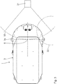
- eine Vorrichtung zum Bearbeiten von Teig in einer im Bereich einer Verbindung zwischen der Bearbeitungsvorrichtung und einem Teigbottich teilweise geschnitten dargestellten Seitenansicht;
- Fig. 2
- vergrößert das Detail II in
Fig. 1 ; - Fig. 3
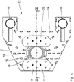
- eine Aufsicht auf die Bearbeitungsvorrichtung;
- Fig. 4
- perspektivisch eine Halteeinrichtung der Bearbeitungsvorrichtung zur lösbaren Halterung des Teigbottichs;
- Fig. 5
- eine Aufsicht auf die Halteeinrichtung nach
Fig. 4 ; - Fig. 6
- einen Schnitt gemäß VI-VI in
Fig. 5 ; und - Fig. 7
- perspektivisch den Teigbottich der Bearbeitungsvorrichtung.
- Fig. 1
- a device for processing dough in a partially cut in the region of a connection between the processing device and a Teigbottich side view;
- Fig. 2
- enlarges the detail II in
Fig. 1 ; - Fig. 3
- a view of the processing device;
- Fig. 4
- in perspective, a holding device of the processing device for releasably holding the Teigbottichs;
- Fig. 5
- a view of the holding device according to
Fig. 4 ; - Fig. 6
- a section according to VI-VI in
Fig. 5 ; and - Fig. 7
- in perspective, the Teigbottich the processing device.
Eine Bearbeitungsvorrichtung 1 zum Bearbeiten und insbesondere zum Mischen und Kneten von Teig hat einen Tragrahmen 2 innerhalb eines Maschinengehäuses 3 mit einem Ständer 4 und einem Arm 5, der auch als Kopf bezeichnet ist. Ein Bottich 6 der Bearbeitungsvorrichtung 1 dient zur Aufnahme des zu knetenden und zu mischenden Teiges. Der Bottich 6 ist perspektivisch in der
An einer Rahmenplatte des Tragrahmens 2, die innerhalb des Arms 5 verläuft, gelagert ist ein Knetwerkzeug 7 in Form einer vertikalen Doppel-Knetspirale. Bei der Bearbeitungsvorrichtung 1 handelt es sich also um einen Doppelwerkzeugkneter mit zwei Knetspiralen. Das Knetwerkzeug 7 ist in der
Ein Volumen innerhalb des sich um eine Hochachse 9 angetrieben drehbaren Bottichs 6, das beim Betrieb des Knetwerkzeugs 7 von diesem geknetet und gemischt werden kann, gibt eine Knetzone vor. Außerhalb der Knetzone liegt der zu knetende und zu mischende Teig in einer Ruhezone vor. Zwischen der Knetzone und der Ruhezone des Bottichs 6 ist im Bereich der Hochachse 9 ein Leitkörper 10 des Knetwerkzeugs 7 zum Leiten einer Bewegung des Teiges im Bottich 6 angeordnet. Zwischen dem Leitkörper 10 und der Ruhezone kann sich im Betrieb der Bearbeitungsvorrichtung 1 eine vertikal verlaufende Luftsäule innerhalb des Bottichs 6 ausbilden.A volume within the
Der Bottich 6 wird im Betrieb der Bearbeitungsvorrichtung 1 motorisch in an sich bekannter Weise um die Hochachse 9 gedreht. Dies geschieht über einen Reibradantrieb, der in einer Ruhestellung vom Bottich 6 weg geschwenkt wird.The
Weiterhin wird das Knetwerkzeug 7 um eine zentrale, ebenfalls vertikal verlaufende Knetspiralachse 11, die parallel beabstandet zur Hochachse 9 verläuft, motorisch angetrieben. Dieser Knetantrieb ist im Deckel 7a des Knetwerkzeugs 7 untergebracht.Furthermore, the kneading tool 7 is driven by a central, also vertically extending
Die Bearbeitungsvorrichtung 1 hat eine Halteeinrichtung 12 zur lösbaren Halterung des Teigbottichs 6. Diese Halteeinrichtung 12, die auch als Kesselaufnahme bezeichnet ist, ist insgesamt in den
Die Halteeinrichtung 12 hat einen Klemmstempel 15 zur Anlage an einer Unterseite 16 eines bodenseitig am Teigbottich 6 angebrachten Bottich-Klemmfußes 17. Diese Anlage des Klemmstempels 15 am Bottich-Klemmfuß 17 erfolgt mit einer Klemmkraft in axialer Richtung längs der Bottich-Hochachse 9. Eine Anlagewand 18 des Klemmstempels 15 ist zur Anlage an der Unterseite 16 des Bottich-Klemmfußes 17 profiliert ausgeführt. Diese Profilierung ist als um die Anlagewand 18 außen umlaufender, erhabener Spannring 19 ausgeführt. Die Unterseite 16 des Bottich-Klemmfußes 17 des Bottichs 6 ist mit einer komplementär zu dieser Profilierung der Anlagewand 18 ausgeführten Gegenprofilierung ausgebildet. Diese Gegenprofilierung weist eine komplementär zum Spannring 19 ausgestaltete umlaufende Ausnehmung 20 auf.The holding
Der Klemmstempel 15 ist axial angetrieben relativ zur Grundrahmenplatte 14 und relativ zu einem in Bezug auf die Grundrahmenplatte 14 stationären Gegen-Klemmkörper 21 verlagerbar. Für diesen Axialantrieb des Klemmstempels 15 hat die Halteeinrichtung 12 einen hydraulischen Hubzylinder 22, der unterhalb des Klemmstempels 15 angeordnet und an der Grundrahmenplatte 14 festgelegt ist. Im Hubzylinder 22 läuft ein Hubkolben 23, dessen freies Ende mit dem Klemmstempel 15 verschraubt ist.The clamping
Anstelle eines hydraulischen Antriebs kann ein Axialantrieb für den Klemmstempel 15 auch durch einen anderen Antriebstyp realisiert sein.Instead of a hydraulic drive, an axial drive for the clamping
Der Gegen-Klemmkörper 21 der Halteeinrichtung 12 dient zum Hintergreifen des Bottich-Klemmfußes 17 zwischen dem Bottich-Klemmfuß 17 und einem Bottichbehälter 24 des Teigbottichs 6. In der in den
Der Gegen-Klemmkörper 21 ist zweiteilig ausgeführt und hat zwei Klemmschienen 25, 26, zwischen denen ein bogenförmiger Zwischenraum 27 vorliegt. Die beiden Klemmschienen 25, 26 sind über Distanzträger 28 mit der Grundrahmenplatte 14 verschweißt.The
Zwischen dem Bolzen 13 und der Grundplatte 14 sind keilförmige Knotenbleche zur Aufnahme von Kräften angeordnet.Between the
Die beiden Klemmschienen 25, 26 hintergreifen den im Zwischenraum 27 angeordneten Bottich-Klemmfuß 17 beidseitig.The two
Der Bottich-Klemmfuß 17 des Teigbottichs 6 ist um die Bottich-Hochachse 9 drehbar am Bottichbehälter 24 gelagert. Diese Lagerung ist gegeben durch ein Kugellager 29. Letzteres stellt ein Axial-/Radiallager dar. Das Kugellager 29 bildet eine hintergreifende Aufnahme, die einen den Boden des Bottichbehälters 24 zugewandten Umfangsbund 30 des Bottich-Klemmfußes 17 hintergreift. Bei festgelegtem Bottich-Klemmfuß 17 kann sich der Bottichbehälter 24 also um die Bottich-Hochachse 9 drehen.The
Die Bearbeitungsvorrichtung 1 kann Bestandteil eines Bearbeitungskarussells mit mehreren Bearbeitungsstationen zur Teigbearbeitung sein. Diese anderen Bearbeitungsstationen sind nicht dargestellt. Zur Verlagerung des Teigbottichs 6 in eine mit der Klemmstellung übereinstimmende Bearbeitungsposition des Teigbottichs 6 zur Bearbeitung des Teiges durch die Bearbeitungsvorrichtung 1 und zur Verlagerung des Teigbottichs 6 aus der Bearbeitungsposition hin zu einer weiteren Position zur Bearbeitung durch eine weitere Bearbeitungsvorrichtung oder Bearbeitungsstation des Karussells dient ein in der
Beim Betrieb des Bearbeitungskarussells wird der Teig im Teigbottich 6 zunächst in der Bearbeitungsvorrichtung 1 vorgelagerten Bearbeitungsstation zum Kneten und Mischen vorbereitet. Anschließend wird der Teigbottich 6 längs der Bahn 32 in die Bearbeitungsposition verlagert, bei der eine Rotations-Symmetrieachse des Klemmstempels 15 mit der Bottich-Hochachse 9 fluchtet. Eine Zwischenstellung des Teigbottichs 6 auf dem Verlagerungsweg hin zu der Bearbeitungsposition ist in der
Beim Verlagern in die Bearbeitungsposition liegt die Halteeinrichtung 12 zunächst in einer Freigabestellung vor, bei der der Hubkolben 23 in den Hubzylinder 22 eingezogen ist. In dieser Freigabestellung liegt in axialer Richtung zwischen dem Klemmstempel 15 und dem Gegen-Klemmkörper 21, also den beiden Klemmschienen 25, 26 ein Zwischenraum vor, der so groß ist, dass der Bottich-Klemmfuß 17 längs der Bahn 32 von der Seite her in die Halteeinrichtung 12 eingefahren werden kann. Sobald der Bottich 6 die Bearbeitungsposition erreicht hat, wird der Hubzylinder 22 beaufschlagt und der Hubkolben 23 ausgefahren, so dass die Halteeinrichtung 12 die Klemmstellung, die in der
Ein Umstellen des Hubkolbens 23 von der Freigabestellung in die Klemmstellung dauert etwa 2 s.A changeover of the
Bei einer nicht dargestellten Ausführungsform ist der Klemmstempel stationär zur Grundrahmenplatte 14 angeordnet und der Gegen-Klemmkörper, ausgebildet insbesondere durch die beiden Klemmschienen, wird axial zum Erreichen der Klemmstellung auf den Klemmstempel 15 angetrieben zu bewegt.In one embodiment, not shown, the clamping punch is arranged stationary to the
In der Klemmstellung ist der Spannring 19 des Klemmstempels 15 in der umlaufenden Ringnut 20 des Bottich-Klemmfußes 17 aufgenommen, so dass der Teigbottich 6 relativ zum Tragrahmen 2 der Bearbeitungsvorrichtung 1 exakt positioniert ist. Nun kann das Knetwerkzeug 7 aus der in der
Der Gegen-Klemmkörper 21 kann bei einer nicht dargestellten Ausführung der Bearbeitungsvorrichtung auch einteilig ausgeführt sein. Geklemmt werden kann beispielsweise radial außerhalb oder radial innerhalb der Bahn 32.The
Die perspektivische Darstellung des Bottich-Klemmfußes 17 nach
Claims (8)
Applications Claiming Priority (1)
| Application Number | Priority Date | Filing Date | Title |
|---|---|---|---|
| DE102011004433A DE102011004433A1 (en) | 2011-02-21 | 2011-02-21 | Device for processing dough |
Publications (3)
| Publication Number | Publication Date |
|---|---|
| EP2489271A2 true EP2489271A2 (en) | 2012-08-22 |
| EP2489271A3 EP2489271A3 (en) | 2013-04-17 |
| EP2489271B1 EP2489271B1 (en) | 2016-07-20 |
Family
ID=45655779
Family Applications (1)
| Application Number | Title | Priority Date | Filing Date |
|---|---|---|---|
| EP12155483.6A Not-in-force EP2489271B1 (en) | 2011-02-21 | 2012-02-15 | Device for processing dough |
Country Status (2)
| Country | Link |
|---|---|
| EP (1) | EP2489271B1 (en) |
| DE (1) | DE102011004433A1 (en) |
Cited By (2)
| Publication number | Priority date | Publication date | Assignee | Title |
|---|---|---|---|---|
| CN107185435A (en) * | 2017-07-18 | 2017-09-22 | 深圳市江途机械科技有限公司 | A kind of environmental protection coating material device |
| CN110170267A (en) * | 2019-06-06 | 2019-08-27 | 上海外高桥造船有限公司 | A kind of inorganic zinc silicate primer self- poking arrangement |
Citations (6)
| Publication number | Priority date | Publication date | Assignee | Title |
|---|---|---|---|---|
| DE296789C (en) | ||||
| DE68903071T2 (en) | 1988-07-05 | 1993-02-18 | Sancassiano Spa | Kneading machine for food products, especially flour mixes. |
| DE19820272C2 (en) | 1998-05-07 | 2002-10-31 | Diosna Dierks & Soehne Gmbh | Equipment for preparing dough for baked goods |
| DE60006433T2 (en) | 1999-02-10 | 2004-09-09 | Vmi | Mounting arrangement of a grille for a mixing device |
| DE60304657T2 (en) | 2002-11-26 | 2006-08-31 | Sancassiano S.P.A., Roddi D'alba | Dough mixer for dough products, in particular for baked goods |
| DE602004008152T2 (en) | 2003-06-17 | 2008-05-08 | Vmi | System for resiliently holding a container with respect to a mixing head of a mixer |
Family Cites Families (5)
| Publication number | Priority date | Publication date | Assignee | Title |
|---|---|---|---|---|
| US2791405A (en) * | 1954-05-24 | 1957-05-07 | Liston Sol | Continuous automatic dough making means |
| US3877683A (en) * | 1974-03-22 | 1975-04-15 | Scm Corp | Batch tinting apparatus |
| IT1165694B (en) * | 1979-07-23 | 1987-04-22 | Costa Rinaldo | MIXER MACHINE IN PARTICULAR USEFUL FOR FOOD PRODUCTS |
| IT1155169B (en) * | 1982-04-27 | 1987-01-21 | Rinaldo Costa | FOOD MIXER MACHINE |
| SE431152B (en) * | 1983-04-06 | 1984-01-23 | Glimek Ab | Device for fixing a mixing vessel to the mixer |
-
2011
- 2011-02-21 DE DE102011004433A patent/DE102011004433A1/en not_active Ceased
-
2012
- 2012-02-15 EP EP12155483.6A patent/EP2489271B1/en not_active Not-in-force
Patent Citations (6)
| Publication number | Priority date | Publication date | Assignee | Title |
|---|---|---|---|---|
| DE296789C (en) | ||||
| DE68903071T2 (en) | 1988-07-05 | 1993-02-18 | Sancassiano Spa | Kneading machine for food products, especially flour mixes. |
| DE19820272C2 (en) | 1998-05-07 | 2002-10-31 | Diosna Dierks & Soehne Gmbh | Equipment for preparing dough for baked goods |
| DE60006433T2 (en) | 1999-02-10 | 2004-09-09 | Vmi | Mounting arrangement of a grille for a mixing device |
| DE60304657T2 (en) | 2002-11-26 | 2006-08-31 | Sancassiano S.P.A., Roddi D'alba | Dough mixer for dough products, in particular for baked goods |
| DE602004008152T2 (en) | 2003-06-17 | 2008-05-08 | Vmi | System for resiliently holding a container with respect to a mixing head of a mixer |
Cited By (3)
| Publication number | Priority date | Publication date | Assignee | Title |
|---|---|---|---|---|
| CN107185435A (en) * | 2017-07-18 | 2017-09-22 | 深圳市江途机械科技有限公司 | A kind of environmental protection coating material device |
| CN107185435B (en) * | 2017-07-18 | 2018-11-02 | 台州云造智能科技有限公司 | A kind of environmental protection coating material device |
| CN110170267A (en) * | 2019-06-06 | 2019-08-27 | 上海外高桥造船有限公司 | A kind of inorganic zinc silicate primer self- poking arrangement |
Also Published As
| Publication number | Publication date |
|---|---|
| DE102011004433A1 (en) | 2012-08-23 |
| EP2489271A3 (en) | 2013-04-17 |
| EP2489271B1 (en) | 2016-07-20 |
Similar Documents
| Publication | Publication Date | Title |
|---|---|---|
| EP2208549B1 (en) | Rotation stretch bending tool with eccentric clamp | |
| DE60129375T2 (en) | Reifenabdrückvorrichtung for a Raddemontiergerät, and Raddemontiergerät with such a device | |
| DE2760355C2 (en) | ||
| EP2036629A1 (en) | Method and device for fine cutting and forming of a workpiece | |
| CH657567A5 (en) | REVOLVER PUNCH. | |
| EP3450042B1 (en) | Combination tool | |
| WO2017220393A1 (en) | Device for calibrating and straightening hollow components and method with such a device | |
| DE102007057790B4 (en) | Rotary press | |
| DE102008006045B4 (en) | tablet press | |
| DE2314858A1 (en) | DEVICE FOR PROCESSING METALLIC WORKPIECES | |
| EP2489271B1 (en) | Device for processing dough | |
| WO2016050362A1 (en) | Replacement device for clamping and/or centering subassemblies | |
| EP2873512A1 (en) | Method and device for stamping and connecting plastic pieces | |
| DE2527248A1 (en) | PUNCHING UNIT | |
| EP3515622B1 (en) | Tool, machine tool, and method for cutting and/or forming planar workpieces | |
| EP1056556A1 (en) | Flanging device with pressing and clamping elements | |
| DE3908582C2 (en) | ||
| EP3025802A1 (en) | Device and method for pressure rolling workpieces | |
| DE3045089A1 (en) | Round section cutting-out shear - has additional drive for rotary knives surrounding central clamping mechanism | |
| DE3727817A1 (en) | ASSEMBLY DEVICE FOR AT LEAST ONE TIRE | |
| DE19811418B4 (en) | Collet for a cutting machine | |
| EP1638711B1 (en) | Embossing machine and method for embossing workpieces | |
| DE102012004605B4 (en) | Process and tool for machining bearing points in a brake caliper | |
| DE754923C (en) | Device for the automatic production and wrapping of staples in continuously moving workpieces carried by cylinders, especially on staplers of rotary printing machines | |
| DE102008033845B3 (en) | Tool guide unit for molding press for manufacturing e.g. arc-shaped board, in automotive industry, has counter bearing guided and supported on movable bridge, where bridge stays in effective connection with base frame of processing machine |
Legal Events
| Date | Code | Title | Description |
|---|---|---|---|
| PUAI | Public reference made under article 153(3) epc to a published international application that has entered the european phase |
Free format text: ORIGINAL CODE: 0009012 |
|
| AK | Designated contracting states |
Kind code of ref document: A2 Designated state(s): AL AT BE BG CH CY CZ DE DK EE ES FI FR GB GR HR HU IE IS IT LI LT LU LV MC MK MT NL NO PL PT RO RS SE SI SK SM TR |
|
| AX | Request for extension of the european patent |
Extension state: BA ME |
|
| PUAL | Search report despatched |
Free format text: ORIGINAL CODE: 0009013 |
|
| AK | Designated contracting states |
Kind code of ref document: A3 Designated state(s): AL AT BE BG CH CY CZ DE DK EE ES FI FR GB GR HR HU IE IS IT LI LT LU LV MC MK MT NL NO PL PT RO RS SE SI SK SM TR |
|
| AX | Request for extension of the european patent |
Extension state: BA ME |
|
| RIC1 | Information provided on ipc code assigned before grant |
Ipc: A21C 1/14 20060101ALI20130312BHEP Ipc: A21C 1/02 20060101AFI20130312BHEP Ipc: B01F 7/16 20060101ALI20130312BHEP Ipc: B01F 13/10 20060101ALI20130312BHEP Ipc: B01F 15/00 20060101ALI20130312BHEP |
|
| 17P | Request for examination filed |
Effective date: 20130920 |
|
| RBV | Designated contracting states (corrected) |
Designated state(s): AL AT BE BG CH CY CZ DE DK EE ES FI FR GB GR HR HU IE IS IT LI LT LU LV MC MK MT NL NO PL PT RO RS SE SI SK SM TR |
|
| 17Q | First examination report despatched |
Effective date: 20140102 |
|
| GRAP | Despatch of communication of intention to grant a patent |
Free format text: ORIGINAL CODE: EPIDOSNIGR1 |
|
| INTG | Intention to grant announced |
Effective date: 20160212 |
|
| GRAS | Grant fee paid |
Free format text: ORIGINAL CODE: EPIDOSNIGR3 |
|
| GRAA | (expected) grant |
Free format text: ORIGINAL CODE: 0009210 |
|
| AK | Designated contracting states |
Kind code of ref document: B1 Designated state(s): AL AT BE BG CH CY CZ DE DK EE ES FI FR GB GR HR HU IE IS IT LI LT LU LV MC MK MT NL NO PL PT RO RS SE SI SK SM TR |
|
| REG | Reference to a national code |
Ref country code: GB Ref legal event code: FG4D Free format text: NOT ENGLISH |
|
| REG | Reference to a national code |
Ref country code: CH Ref legal event code: EP |
|
| REG | Reference to a national code |
Ref country code: IE Ref legal event code: FG4D Free format text: LANGUAGE OF EP DOCUMENT: GERMAN |
|
| REG | Reference to a national code |
Ref country code: AT Ref legal event code: REF Ref document number: 813226 Country of ref document: AT Kind code of ref document: T Effective date: 20160815 |
|
| REG | Reference to a national code |
Ref country code: DE Ref legal event code: R096 Ref document number: 502012007685 Country of ref document: DE |
|
| REG | Reference to a national code |
Ref country code: LT Ref legal event code: MG4D |
|
| REG | Reference to a national code |
Ref country code: NL Ref legal event code: MP Effective date: 20160720 |
|
| PG25 | Lapsed in a contracting state [announced via postgrant information from national office to epo] |
Ref country code: NO Free format text: LAPSE BECAUSE OF FAILURE TO SUBMIT A TRANSLATION OF THE DESCRIPTION OR TO PAY THE FEE WITHIN THE PRESCRIBED TIME-LIMIT Effective date: 20161020 Ref country code: IS Free format text: LAPSE BECAUSE OF FAILURE TO SUBMIT A TRANSLATION OF THE DESCRIPTION OR TO PAY THE FEE WITHIN THE PRESCRIBED TIME-LIMIT Effective date: 20161120 Ref country code: RS Free format text: LAPSE BECAUSE OF FAILURE TO SUBMIT A TRANSLATION OF THE DESCRIPTION OR TO PAY THE FEE WITHIN THE PRESCRIBED TIME-LIMIT Effective date: 20160720 Ref country code: LT Free format text: LAPSE BECAUSE OF FAILURE TO SUBMIT A TRANSLATION OF THE DESCRIPTION OR TO PAY THE FEE WITHIN THE PRESCRIBED TIME-LIMIT Effective date: 20160720 Ref country code: NL Free format text: LAPSE BECAUSE OF FAILURE TO SUBMIT A TRANSLATION OF THE DESCRIPTION OR TO PAY THE FEE WITHIN THE PRESCRIBED TIME-LIMIT Effective date: 20160720 Ref country code: FI Free format text: LAPSE BECAUSE OF FAILURE TO SUBMIT A TRANSLATION OF THE DESCRIPTION OR TO PAY THE FEE WITHIN THE PRESCRIBED TIME-LIMIT Effective date: 20160720 Ref country code: HR Free format text: LAPSE BECAUSE OF FAILURE TO SUBMIT A TRANSLATION OF THE DESCRIPTION OR TO PAY THE FEE WITHIN THE PRESCRIBED TIME-LIMIT Effective date: 20160720 |
|
| PG25 | Lapsed in a contracting state [announced via postgrant information from national office to epo] |
Ref country code: GR Free format text: LAPSE BECAUSE OF FAILURE TO SUBMIT A TRANSLATION OF THE DESCRIPTION OR TO PAY THE FEE WITHIN THE PRESCRIBED TIME-LIMIT Effective date: 20161021 Ref country code: SE Free format text: LAPSE BECAUSE OF FAILURE TO SUBMIT A TRANSLATION OF THE DESCRIPTION OR TO PAY THE FEE WITHIN THE PRESCRIBED TIME-LIMIT Effective date: 20160720 Ref country code: PL Free format text: LAPSE BECAUSE OF FAILURE TO SUBMIT A TRANSLATION OF THE DESCRIPTION OR TO PAY THE FEE WITHIN THE PRESCRIBED TIME-LIMIT Effective date: 20160720 Ref country code: ES Free format text: LAPSE BECAUSE OF FAILURE TO SUBMIT A TRANSLATION OF THE DESCRIPTION OR TO PAY THE FEE WITHIN THE PRESCRIBED TIME-LIMIT Effective date: 20160720 Ref country code: LV Free format text: LAPSE BECAUSE OF FAILURE TO SUBMIT A TRANSLATION OF THE DESCRIPTION OR TO PAY THE FEE WITHIN THE PRESCRIBED TIME-LIMIT Effective date: 20160720 Ref country code: PT Free format text: LAPSE BECAUSE OF FAILURE TO SUBMIT A TRANSLATION OF THE DESCRIPTION OR TO PAY THE FEE WITHIN THE PRESCRIBED TIME-LIMIT Effective date: 20161121 |
|
| REG | Reference to a national code |
Ref country code: DE Ref legal event code: R097 Ref document number: 502012007685 Country of ref document: DE |
|
| PG25 | Lapsed in a contracting state [announced via postgrant information from national office to epo] |
Ref country code: RO Free format text: LAPSE BECAUSE OF FAILURE TO SUBMIT A TRANSLATION OF THE DESCRIPTION OR TO PAY THE FEE WITHIN THE PRESCRIBED TIME-LIMIT Effective date: 20160720 Ref country code: EE Free format text: LAPSE BECAUSE OF FAILURE TO SUBMIT A TRANSLATION OF THE DESCRIPTION OR TO PAY THE FEE WITHIN THE PRESCRIBED TIME-LIMIT Effective date: 20160720 |
|
| PLBE | No opposition filed within time limit |
Free format text: ORIGINAL CODE: 0009261 |
|
| STAA | Information on the status of an ep patent application or granted ep patent |
Free format text: STATUS: NO OPPOSITION FILED WITHIN TIME LIMIT |
|
| PG25 | Lapsed in a contracting state [announced via postgrant information from national office to epo] |
Ref country code: CZ Free format text: LAPSE BECAUSE OF FAILURE TO SUBMIT A TRANSLATION OF THE DESCRIPTION OR TO PAY THE FEE WITHIN THE PRESCRIBED TIME-LIMIT Effective date: 20160720 Ref country code: BG Free format text: LAPSE BECAUSE OF FAILURE TO SUBMIT A TRANSLATION OF THE DESCRIPTION OR TO PAY THE FEE WITHIN THE PRESCRIBED TIME-LIMIT Effective date: 20161020 Ref country code: DK Free format text: LAPSE BECAUSE OF FAILURE TO SUBMIT A TRANSLATION OF THE DESCRIPTION OR TO PAY THE FEE WITHIN THE PRESCRIBED TIME-LIMIT Effective date: 20160720 Ref country code: BE Free format text: LAPSE BECAUSE OF NON-PAYMENT OF DUE FEES Effective date: 20170228 Ref country code: SK Free format text: LAPSE BECAUSE OF FAILURE TO SUBMIT A TRANSLATION OF THE DESCRIPTION OR TO PAY THE FEE WITHIN THE PRESCRIBED TIME-LIMIT Effective date: 20160720 Ref country code: SM Free format text: LAPSE BECAUSE OF FAILURE TO SUBMIT A TRANSLATION OF THE DESCRIPTION OR TO PAY THE FEE WITHIN THE PRESCRIBED TIME-LIMIT Effective date: 20160720 |
|
| 26N | No opposition filed |
Effective date: 20170421 |
|
| PG25 | Lapsed in a contracting state [announced via postgrant information from national office to epo] |
Ref country code: SI Free format text: LAPSE BECAUSE OF FAILURE TO SUBMIT A TRANSLATION OF THE DESCRIPTION OR TO PAY THE FEE WITHIN THE PRESCRIBED TIME-LIMIT Effective date: 20160720 |
|
| REG | Reference to a national code |
Ref country code: DE Ref legal event code: R119 Ref document number: 502012007685 Country of ref document: DE |
|
| PG25 | Lapsed in a contracting state [announced via postgrant information from national office to epo] |
Ref country code: MC Free format text: LAPSE BECAUSE OF FAILURE TO SUBMIT A TRANSLATION OF THE DESCRIPTION OR TO PAY THE FEE WITHIN THE PRESCRIBED TIME-LIMIT Effective date: 20160720 |
|
| REG | Reference to a national code |
Ref country code: CH Ref legal event code: PL |
|
| GBPC | Gb: european patent ceased through non-payment of renewal fee |
Effective date: 20170215 |
|
| PG25 | Lapsed in a contracting state [announced via postgrant information from national office to epo] |
Ref country code: LI Free format text: LAPSE BECAUSE OF NON-PAYMENT OF DUE FEES Effective date: 20170228 Ref country code: CH Free format text: LAPSE BECAUSE OF NON-PAYMENT OF DUE FEES Effective date: 20170228 |
|
| REG | Reference to a national code |
Ref country code: IE Ref legal event code: MM4A |
|
| REG | Reference to a national code |
Ref country code: FR Ref legal event code: ST Effective date: 20171031 |
|
| PG25 | Lapsed in a contracting state [announced via postgrant information from national office to epo] |
Ref country code: LU Free format text: LAPSE BECAUSE OF NON-PAYMENT OF DUE FEES Effective date: 20170215 |
|
| PG25 | Lapsed in a contracting state [announced via postgrant information from national office to epo] |
Ref country code: DE Free format text: LAPSE BECAUSE OF NON-PAYMENT OF DUE FEES Effective date: 20170901 Ref country code: FR Free format text: LAPSE BECAUSE OF NON-PAYMENT OF DUE FEES Effective date: 20170228 |
|
| REG | Reference to a national code |
Ref country code: BE Ref legal event code: MM Effective date: 20170228 |
|
| PG25 | Lapsed in a contracting state [announced via postgrant information from national office to epo] |
Ref country code: IE Free format text: LAPSE BECAUSE OF NON-PAYMENT OF DUE FEES Effective date: 20170215 Ref country code: IT Free format text: LAPSE BECAUSE OF NON-PAYMENT OF DUE FEES Effective date: 20170215 Ref country code: GB Free format text: LAPSE BECAUSE OF NON-PAYMENT OF DUE FEES Effective date: 20170215 |
|
| REG | Reference to a national code |
Ref country code: AT Ref legal event code: MM01 Ref document number: 813226 Country of ref document: AT Kind code of ref document: T Effective date: 20170215 |
|
| PG25 | Lapsed in a contracting state [announced via postgrant information from national office to epo] |
Ref country code: AT Free format text: LAPSE BECAUSE OF NON-PAYMENT OF DUE FEES Effective date: 20170215 |
|
| PG25 | Lapsed in a contracting state [announced via postgrant information from national office to epo] |
Ref country code: MT Free format text: LAPSE BECAUSE OF FAILURE TO SUBMIT A TRANSLATION OF THE DESCRIPTION OR TO PAY THE FEE WITHIN THE PRESCRIBED TIME-LIMIT Effective date: 20160720 |
|
| PG25 | Lapsed in a contracting state [announced via postgrant information from national office to epo] |
Ref country code: AL Free format text: LAPSE BECAUSE OF FAILURE TO SUBMIT A TRANSLATION OF THE DESCRIPTION OR TO PAY THE FEE WITHIN THE PRESCRIBED TIME-LIMIT Effective date: 20160720 |
|
| PG25 | Lapsed in a contracting state [announced via postgrant information from national office to epo] |
Ref country code: HU Free format text: LAPSE BECAUSE OF FAILURE TO SUBMIT A TRANSLATION OF THE DESCRIPTION OR TO PAY THE FEE WITHIN THE PRESCRIBED TIME-LIMIT; INVALID AB INITIO Effective date: 20120215 |
|
| PG25 | Lapsed in a contracting state [announced via postgrant information from national office to epo] |
Ref country code: CY Free format text: LAPSE BECAUSE OF NON-PAYMENT OF DUE FEES Effective date: 20160720 |
|
| PG25 | Lapsed in a contracting state [announced via postgrant information from national office to epo] |
Ref country code: MK Free format text: LAPSE BECAUSE OF FAILURE TO SUBMIT A TRANSLATION OF THE DESCRIPTION OR TO PAY THE FEE WITHIN THE PRESCRIBED TIME-LIMIT Effective date: 20160720 |
|
| PG25 | Lapsed in a contracting state [announced via postgrant information from national office to epo] |
Ref country code: TR Free format text: LAPSE BECAUSE OF FAILURE TO SUBMIT A TRANSLATION OF THE DESCRIPTION OR TO PAY THE FEE WITHIN THE PRESCRIBED TIME-LIMIT Effective date: 20160720 |