EP2488871B1 - Procédé d'analyse mettant en jeu l'utilisation de particules magnétiques - Google Patents
Procédé d'analyse mettant en jeu l'utilisation de particules magnétiques Download PDFInfo
- Publication number
- EP2488871B1 EP2488871B1 EP10774160.5A EP10774160A EP2488871B1 EP 2488871 B1 EP2488871 B1 EP 2488871B1 EP 10774160 A EP10774160 A EP 10774160A EP 2488871 B1 EP2488871 B1 EP 2488871B1
- Authority
- EP
- European Patent Office
- Prior art keywords
- sample
- magnetic
- flow path
- capture
- analyte
- Prior art date
- Legal status (The legal status is an assumption and is not a legal conclusion. Google has not performed a legal analysis and makes no representation as to the accuracy of the status listed.)
- Active
Links
- 238000003556 assay Methods 0.000 title claims description 143
- 239000006249 magnetic particle Substances 0.000 title claims description 63
- 230000005291 magnetic effect Effects 0.000 claims description 94
- 239000012491 analyte Substances 0.000 claims description 57
- 238000001514 detection method Methods 0.000 claims description 56
- 238000006243 chemical reaction Methods 0.000 claims description 47
- 238000000034 method Methods 0.000 claims description 32
- 238000009739 binding Methods 0.000 claims description 27
- 230000027455 binding Effects 0.000 claims description 26
- 239000000758 substrate Substances 0.000 claims description 13
- 239000007788 liquid Substances 0.000 claims description 12
- 230000002285 radioactive effect Effects 0.000 claims description 9
- 210000002966 serum Anatomy 0.000 claims description 7
- 108090000790 Enzymes Proteins 0.000 claims description 6
- 102000004190 Enzymes Human genes 0.000 claims description 6
- 150000007523 nucleic acids Chemical group 0.000 claims description 6
- 108091023037 Aptamer Proteins 0.000 claims description 5
- 108010021625 Immunoglobulin Fragments Proteins 0.000 claims description 5
- 102000008394 Immunoglobulin Fragments Human genes 0.000 claims description 5
- 238000000151 deposition Methods 0.000 claims description 5
- 206010036790 Productive cough Diseases 0.000 claims description 4
- 238000001574 biopsy Methods 0.000 claims description 4
- 210000004369 blood Anatomy 0.000 claims description 4
- 239000008280 blood Substances 0.000 claims description 4
- 210000002381 plasma Anatomy 0.000 claims description 4
- 210000003296 saliva Anatomy 0.000 claims description 4
- 210000003802 sputum Anatomy 0.000 claims description 4
- 208000024794 sputum Diseases 0.000 claims description 4
- 210000001519 tissue Anatomy 0.000 claims description 4
- 210000002700 urine Anatomy 0.000 claims description 4
- 241000124008 Mammalia Species 0.000 claims description 3
- 239000000523 sample Substances 0.000 description 92
- 239000002245 particle Substances 0.000 description 23
- 239000011324 bead Substances 0.000 description 17
- 239000000463 material Substances 0.000 description 15
- 108010074051 C-Reactive Protein Proteins 0.000 description 12
- 102100032752 C-reactive protein Human genes 0.000 description 12
- 150000001875 compounds Chemical class 0.000 description 8
- 230000001976 improved effect Effects 0.000 description 8
- 239000007791 liquid phase Substances 0.000 description 7
- 239000000020 Nitrocellulose Substances 0.000 description 6
- 238000002474 experimental method Methods 0.000 description 6
- 239000012530 fluid Substances 0.000 description 6
- 229920001220 nitrocellulos Polymers 0.000 description 6
- 230000035945 sensitivity Effects 0.000 description 6
- 238000012360 testing method Methods 0.000 description 6
- 230000004913 activation Effects 0.000 description 5
- 239000012501 chromatography medium Substances 0.000 description 5
- -1 fleece Substances 0.000 description 5
- SZVJSHCCFOBDDC-UHFFFAOYSA-N iron(II,III) oxide Inorganic materials O=[Fe]O[Fe]O[Fe]=O SZVJSHCCFOBDDC-UHFFFAOYSA-N 0.000 description 5
- 230000003213 activating effect Effects 0.000 description 4
- 239000012141 concentrate Substances 0.000 description 4
- 238000013461 design Methods 0.000 description 4
- 239000003446 ligand Substances 0.000 description 4
- 230000000670 limiting effect Effects 0.000 description 4
- 238000002156 mixing Methods 0.000 description 4
- 238000012986 modification Methods 0.000 description 4
- 230000004048 modification Effects 0.000 description 4
- 238000000159 protein binding assay Methods 0.000 description 4
- 239000011541 reaction mixture Substances 0.000 description 4
- 239000007790 solid phase Substances 0.000 description 4
- 230000002255 enzymatic effect Effects 0.000 description 3
- 239000000835 fiber Substances 0.000 description 3
- 238000011534 incubation Methods 0.000 description 3
- 239000003550 marker Substances 0.000 description 3
- 239000000203 mixture Substances 0.000 description 3
- 239000011148 porous material Substances 0.000 description 3
- 230000002035 prolonged effect Effects 0.000 description 3
- 239000011535 reaction buffer Substances 0.000 description 3
- 230000000979 retarding effect Effects 0.000 description 3
- 238000012289 standard assay Methods 0.000 description 3
- 239000012536 storage buffer Substances 0.000 description 3
- 239000000126 substance Substances 0.000 description 3
- 229910000859 α-Fe Inorganic materials 0.000 description 3
- YBJHBAHKTGYVGT-ZKWXMUAHSA-N (+)-Biotin Chemical group N1C(=O)N[C@@H]2[C@H](CCCCC(=O)O)SC[C@@H]21 YBJHBAHKTGYVGT-ZKWXMUAHSA-N 0.000 description 2
- PDLGMYVCPJOYAR-DKIMLUQUSA-N Glu-Leu-Phe-Ala Chemical compound OC(=O)CC[C@H](N)C(=O)N[C@@H](CC(C)C)C(=O)N[C@H](C(=O)N[C@@H](C)C(O)=O)CC1=CC=CC=C1 PDLGMYVCPJOYAR-DKIMLUQUSA-N 0.000 description 2
- VYPSYNLAJGMNEJ-UHFFFAOYSA-N Silicium dioxide Chemical compound O=[Si]=O VYPSYNLAJGMNEJ-UHFFFAOYSA-N 0.000 description 2
- PXIPVTKHYLBLMZ-UHFFFAOYSA-N Sodium azide Chemical compound [Na+].[N-]=[N+]=[N-] PXIPVTKHYLBLMZ-UHFFFAOYSA-N 0.000 description 2
- FAPWRFPIFSIZLT-UHFFFAOYSA-M Sodium chloride Chemical compound [Na+].[Cl-] FAPWRFPIFSIZLT-UHFFFAOYSA-M 0.000 description 2
- 239000003153 chemical reaction reagent Substances 0.000 description 2
- 238000004587 chromatography analysis Methods 0.000 description 2
- 230000008021 deposition Effects 0.000 description 2
- 238000010790 dilution Methods 0.000 description 2
- 239000012895 dilution Substances 0.000 description 2
- 201000010099 disease Diseases 0.000 description 2
- 208000037265 diseases, disorders, signs and symptoms Diseases 0.000 description 2
- 239000002657 fibrous material Substances 0.000 description 2
- 210000004392 genitalia Anatomy 0.000 description 2
- JEIPFZHSYJVQDO-UHFFFAOYSA-N iron(III) oxide Inorganic materials O=[Fe]O[Fe]=O JEIPFZHSYJVQDO-UHFFFAOYSA-N 0.000 description 2
- 238000002372 labelling Methods 0.000 description 2
- 239000011159 matrix material Substances 0.000 description 2
- 239000004005 microsphere Substances 0.000 description 2
- 239000000123 paper Substances 0.000 description 2
- 230000005298 paramagnetic effect Effects 0.000 description 2
- 238000002360 preparation method Methods 0.000 description 2
- 238000012545 processing Methods 0.000 description 2
- 102000004169 proteins and genes Human genes 0.000 description 2
- 108090000623 proteins and genes Proteins 0.000 description 2
- 238000011002 quantification Methods 0.000 description 2
- 238000000926 separation method Methods 0.000 description 2
- 238000005406 washing Methods 0.000 description 2
- LMDZBCPBFSXMTL-UHFFFAOYSA-N 1-Ethyl-3-(3-dimethylaminopropyl)carbodiimide Substances CCN=C=NCCCN(C)C LMDZBCPBFSXMTL-UHFFFAOYSA-N 0.000 description 1
- QKNYBSVHEMOAJP-UHFFFAOYSA-N 2-amino-2-(hydroxymethyl)propane-1,3-diol;hydron;chloride Chemical compound Cl.OCC(N)(CO)CO QKNYBSVHEMOAJP-UHFFFAOYSA-N 0.000 description 1
- 125000000022 2-aminoethyl group Chemical group [H]C([*])([H])C([H])([H])N([H])[H] 0.000 description 1
- 125000000954 2-hydroxyethyl group Chemical group [H]C([*])([H])C([H])([H])O[H] 0.000 description 1
- OALHHIHQOFIMEF-UHFFFAOYSA-N 3',6'-dihydroxy-2',4',5',7'-tetraiodo-3h-spiro[2-benzofuran-1,9'-xanthene]-3-one Chemical compound O1C(=O)C2=CC=CC=C2C21C1=CC(I)=C(O)C(I)=C1OC1=C(I)C(O)=C(I)C=C21 OALHHIHQOFIMEF-UHFFFAOYSA-N 0.000 description 1
- FPQQSJJWHUJYPU-UHFFFAOYSA-N 3-(dimethylamino)propyliminomethylidene-ethylazanium;chloride Chemical compound Cl.CCN=C=NCCCN(C)C FPQQSJJWHUJYPU-UHFFFAOYSA-N 0.000 description 1
- ZCYVEMRRCGMTRW-UHFFFAOYSA-N 7553-56-2 Chemical compound [I] ZCYVEMRRCGMTRW-UHFFFAOYSA-N 0.000 description 1
- 102000002260 Alkaline Phosphatase Human genes 0.000 description 1
- 108020004774 Alkaline Phosphatase Proteins 0.000 description 1
- 108090001008 Avidin Proteins 0.000 description 1
- UXVMQQNJUSDDNG-UHFFFAOYSA-L Calcium chloride Chemical compound [Cl-].[Cl-].[Ca+2] UXVMQQNJUSDDNG-UHFFFAOYSA-L 0.000 description 1
- 206010019280 Heart failures Diseases 0.000 description 1
- 108010001336 Horseradish Peroxidase Proteins 0.000 description 1
- 206010061218 Inflammation Diseases 0.000 description 1
- 239000005089 Luciferase Substances 0.000 description 1
- 108060001084 Luciferase Proteins 0.000 description 1
- 239000007987 MES buffer Substances 0.000 description 1
- PWHULOQIROXLJO-UHFFFAOYSA-N Manganese Chemical compound [Mn] PWHULOQIROXLJO-UHFFFAOYSA-N 0.000 description 1
- 108091034117 Oligonucleotide Proteins 0.000 description 1
- OAICVXFJPJFONN-UHFFFAOYSA-N Phosphorus Chemical compound [P] OAICVXFJPJFONN-UHFFFAOYSA-N 0.000 description 1
- 239000004793 Polystyrene Substances 0.000 description 1
- 229920004890 Triton X-100 Polymers 0.000 description 1
- 239000013504 Triton X-100 Substances 0.000 description 1
- JLCPHMBAVCMARE-UHFFFAOYSA-N [3-[[3-[[3-[[3-[[3-[[3-[[3-[[3-[[3-[[3-[[3-[[5-(2-amino-6-oxo-1H-purin-9-yl)-3-[[3-[[3-[[3-[[3-[[3-[[5-(2-amino-6-oxo-1H-purin-9-yl)-3-[[5-(2-amino-6-oxo-1H-purin-9-yl)-3-hydroxyoxolan-2-yl]methoxy-hydroxyphosphoryl]oxyoxolan-2-yl]methoxy-hydroxyphosphoryl]oxy-5-(5-methyl-2,4-dioxopyrimidin-1-yl)oxolan-2-yl]methoxy-hydroxyphosphoryl]oxy-5-(6-aminopurin-9-yl)oxolan-2-yl]methoxy-hydroxyphosphoryl]oxy-5-(6-aminopurin-9-yl)oxolan-2-yl]methoxy-hydroxyphosphoryl]oxy-5-(6-aminopurin-9-yl)oxolan-2-yl]methoxy-hydroxyphosphoryl]oxy-5-(6-aminopurin-9-yl)oxolan-2-yl]methoxy-hydroxyphosphoryl]oxyoxolan-2-yl]methoxy-hydroxyphosphoryl]oxy-5-(5-methyl-2,4-dioxopyrimidin-1-yl)oxolan-2-yl]methoxy-hydroxyphosphoryl]oxy-5-(4-amino-2-oxopyrimidin-1-yl)oxolan-2-yl]methoxy-hydroxyphosphoryl]oxy-5-(5-methyl-2,4-dioxopyrimidin-1-yl)oxolan-2-yl]methoxy-hydroxyphosphoryl]oxy-5-(5-methyl-2,4-dioxopyrimidin-1-yl)oxolan-2-yl]methoxy-hydroxyphosphoryl]oxy-5-(6-aminopurin-9-yl)oxolan-2-yl]methoxy-hydroxyphosphoryl]oxy-5-(6-aminopurin-9-yl)oxolan-2-yl]methoxy-hydroxyphosphoryl]oxy-5-(4-amino-2-oxopyrimidin-1-yl)oxolan-2-yl]methoxy-hydroxyphosphoryl]oxy-5-(4-amino-2-oxopyrimidin-1-yl)oxolan-2-yl]methoxy-hydroxyphosphoryl]oxy-5-(4-amino-2-oxopyrimidin-1-yl)oxolan-2-yl]methoxy-hydroxyphosphoryl]oxy-5-(6-aminopurin-9-yl)oxolan-2-yl]methoxy-hydroxyphosphoryl]oxy-5-(4-amino-2-oxopyrimidin-1-yl)oxolan-2-yl]methyl [5-(6-aminopurin-9-yl)-2-(hydroxymethyl)oxolan-3-yl] hydrogen phosphate Polymers Cc1cn(C2CC(OP(O)(=O)OCC3OC(CC3OP(O)(=O)OCC3OC(CC3O)n3cnc4c3nc(N)[nH]c4=O)n3cnc4c3nc(N)[nH]c4=O)C(COP(O)(=O)OC3CC(OC3COP(O)(=O)OC3CC(OC3COP(O)(=O)OC3CC(OC3COP(O)(=O)OC3CC(OC3COP(O)(=O)OC3CC(OC3COP(O)(=O)OC3CC(OC3COP(O)(=O)OC3CC(OC3COP(O)(=O)OC3CC(OC3COP(O)(=O)OC3CC(OC3COP(O)(=O)OC3CC(OC3COP(O)(=O)OC3CC(OC3COP(O)(=O)OC3CC(OC3COP(O)(=O)OC3CC(OC3COP(O)(=O)OC3CC(OC3COP(O)(=O)OC3CC(OC3COP(O)(=O)OC3CC(OC3COP(O)(=O)OC3CC(OC3CO)n3cnc4c(N)ncnc34)n3ccc(N)nc3=O)n3cnc4c(N)ncnc34)n3ccc(N)nc3=O)n3ccc(N)nc3=O)n3ccc(N)nc3=O)n3cnc4c(N)ncnc34)n3cnc4c(N)ncnc34)n3cc(C)c(=O)[nH]c3=O)n3cc(C)c(=O)[nH]c3=O)n3ccc(N)nc3=O)n3cc(C)c(=O)[nH]c3=O)n3cnc4c3nc(N)[nH]c4=O)n3cnc4c(N)ncnc34)n3cnc4c(N)ncnc34)n3cnc4c(N)ncnc34)n3cnc4c(N)ncnc34)O2)c(=O)[nH]c1=O JLCPHMBAVCMARE-UHFFFAOYSA-N 0.000 description 1
- 239000002253 acid Substances 0.000 description 1
- 239000000783 alginic acid Substances 0.000 description 1
- 229960001126 alginic acid Drugs 0.000 description 1
- 235000010443 alginic acid Nutrition 0.000 description 1
- 229920000615 alginic acid Polymers 0.000 description 1
- 150000004781 alginic acids Chemical class 0.000 description 1
- 238000003491 array Methods 0.000 description 1
- 239000010425 asbestos Substances 0.000 description 1
- 238000002820 assay format Methods 0.000 description 1
- 102000005936 beta-Galactosidase Human genes 0.000 description 1
- 108010005774 beta-Galactosidase Proteins 0.000 description 1
- 238000004166 bioassay Methods 0.000 description 1
- 239000012620 biological material Substances 0.000 description 1
- 239000012472 biological sample Substances 0.000 description 1
- 239000005082 bioluminescent agent Substances 0.000 description 1
- 229960002685 biotin Drugs 0.000 description 1
- 235000020958 biotin Nutrition 0.000 description 1
- 239000011616 biotin Substances 0.000 description 1
- 210000000601 blood cell Anatomy 0.000 description 1
- 239000000872 buffer Substances 0.000 description 1
- 239000001110 calcium chloride Substances 0.000 description 1
- 229910001628 calcium chloride Inorganic materials 0.000 description 1
- 235000011148 calcium chloride Nutrition 0.000 description 1
- 239000011111 cardboard Substances 0.000 description 1
- 239000000969 carrier Substances 0.000 description 1
- 210000004027 cell Anatomy 0.000 description 1
- 239000001913 cellulose Substances 0.000 description 1
- 229920002678 cellulose Polymers 0.000 description 1
- 238000007385 chemical modification Methods 0.000 description 1
- 239000003795 chemical substances by application Substances 0.000 description 1
- 239000005081 chemiluminescent agent Substances 0.000 description 1
- 238000004140 cleaning Methods 0.000 description 1
- 239000011248 coating agent Substances 0.000 description 1
- 238000000576 coating method Methods 0.000 description 1
- 239000010941 cobalt Substances 0.000 description 1
- 229910017052 cobalt Inorganic materials 0.000 description 1
- GUTLYIVDDKVIGB-UHFFFAOYSA-N cobalt atom Chemical compound [Co] GUTLYIVDDKVIGB-UHFFFAOYSA-N 0.000 description 1
- 239000003086 colorant Substances 0.000 description 1
- 238000011161 development Methods 0.000 description 1
- 230000018109 developmental process Effects 0.000 description 1
- 238000003745 diagnosis Methods 0.000 description 1
- 238000009826 distribution Methods 0.000 description 1
- 239000000975 dye Substances 0.000 description 1
- 238000005516 engineering process Methods 0.000 description 1
- 230000007613 environmental effect Effects 0.000 description 1
- 210000003743 erythrocyte Anatomy 0.000 description 1
- 230000001747 exhibiting effect Effects 0.000 description 1
- 230000005294 ferromagnetic effect Effects 0.000 description 1
- 239000007850 fluorescent dye Substances 0.000 description 1
- 239000003365 glass fiber Substances 0.000 description 1
- 229910052588 hydroxylapatite Inorganic materials 0.000 description 1
- 230000000984 immunochemical effect Effects 0.000 description 1
- 238000010348 incorporation Methods 0.000 description 1
- 230000001939 inductive effect Effects 0.000 description 1
- 230000004054 inflammatory process Effects 0.000 description 1
- 238000002329 infrared spectrum Methods 0.000 description 1
- 230000002452 interceptive effect Effects 0.000 description 1
- 239000011630 iodine Substances 0.000 description 1
- 229910052740 iodine Inorganic materials 0.000 description 1
- HWYHZTIRURJOHG-UHFFFAOYSA-N luminol Chemical compound O=C1NNC(=O)C2=C1C(N)=CC=C2 HWYHZTIRURJOHG-UHFFFAOYSA-N 0.000 description 1
- 238000007726 management method Methods 0.000 description 1
- 229910052748 manganese Inorganic materials 0.000 description 1
- 239000011572 manganese Substances 0.000 description 1
- 238000004519 manufacturing process Methods 0.000 description 1
- 238000005259 measurement Methods 0.000 description 1
- 239000002609 medium Substances 0.000 description 1
- 239000012528 membrane Substances 0.000 description 1
- 239000002105 nanoparticle Substances 0.000 description 1
- 230000009871 nonspecific binding Effects 0.000 description 1
- 108020004707 nucleic acids Proteins 0.000 description 1
- 102000039446 nucleic acids Human genes 0.000 description 1
- 230000010355 oscillation Effects 0.000 description 1
- 230000036961 partial effect Effects 0.000 description 1
- 244000052769 pathogen Species 0.000 description 1
- 230000001717 pathogenic effect Effects 0.000 description 1
- XYJRXVWERLGGKC-UHFFFAOYSA-D pentacalcium;hydroxide;triphosphate Chemical compound [OH-].[Ca+2].[Ca+2].[Ca+2].[Ca+2].[Ca+2].[O-]P([O-])([O-])=O.[O-]P([O-])([O-])=O.[O-]P([O-])([O-])=O XYJRXVWERLGGKC-UHFFFAOYSA-D 0.000 description 1
- 239000005080 phosphorescent agent Substances 0.000 description 1
- 239000011574 phosphorus Substances 0.000 description 1
- 229910052698 phosphorus Inorganic materials 0.000 description 1
- 239000004033 plastic Substances 0.000 description 1
- 229920003023 plastic Polymers 0.000 description 1
- 229920002454 poly(glycidyl methacrylate) polymer Polymers 0.000 description 1
- 229920000642 polymer Polymers 0.000 description 1
- 229920002223 polystyrene Polymers 0.000 description 1
- 238000010791 quenching Methods 0.000 description 1
- 230000000171 quenching effect Effects 0.000 description 1
- 230000002829 reductive effect Effects 0.000 description 1
- 230000000717 retained effect Effects 0.000 description 1
- 229910052895 riebeckite Inorganic materials 0.000 description 1
- 239000000377 silicon dioxide Substances 0.000 description 1
- 239000011780 sodium chloride Substances 0.000 description 1
- 239000012064 sodium phosphate buffer Substances 0.000 description 1
- 239000000243 solution Substances 0.000 description 1
- 230000009870 specific binding Effects 0.000 description 1
- 230000008093 supporting effect Effects 0.000 description 1
- 239000000725 suspension Substances 0.000 description 1
- 230000002459 sustained effect Effects 0.000 description 1
- 229920002994 synthetic fiber Polymers 0.000 description 1
- 239000012209 synthetic fiber Substances 0.000 description 1
- 229920001059 synthetic polymer Polymers 0.000 description 1
- 239000012815 thermoplastic material Substances 0.000 description 1
- 238000011282 treatment Methods 0.000 description 1
- 238000001429 visible spectrum Methods 0.000 description 1
- 230000003313 weakening effect Effects 0.000 description 1
- 238000009736 wetting Methods 0.000 description 1
- 210000002268 wool Anatomy 0.000 description 1
Images


Classifications
-
- G—PHYSICS
- G01—MEASURING; TESTING
- G01N—INVESTIGATING OR ANALYSING MATERIALS BY DETERMINING THEIR CHEMICAL OR PHYSICAL PROPERTIES
- G01N33/00—Investigating or analysing materials by specific methods not covered by groups G01N1/00 - G01N31/00
- G01N33/48—Biological material, e.g. blood, urine; Haemocytometers
- G01N33/50—Chemical analysis of biological material, e.g. blood, urine; Testing involving biospecific ligand binding methods; Immunological testing
- G01N33/53—Immunoassay; Biospecific binding assay; Materials therefor
- G01N33/543—Immunoassay; Biospecific binding assay; Materials therefor with an insoluble carrier for immobilising immunochemicals
- G01N33/54313—Immunoassay; Biospecific binding assay; Materials therefor with an insoluble carrier for immobilising immunochemicals the carrier being characterised by its particulate form
- G01N33/54326—Magnetic particles
-
- B—PERFORMING OPERATIONS; TRANSPORTING
- B01—PHYSICAL OR CHEMICAL PROCESSES OR APPARATUS IN GENERAL
- B01L—CHEMICAL OR PHYSICAL LABORATORY APPARATUS FOR GENERAL USE
- B01L3/00—Containers or dishes for laboratory use, e.g. laboratory glassware; Droppers
- B01L3/50—Containers for the purpose of retaining a material to be analysed, e.g. test tubes
- B01L3/502—Containers for the purpose of retaining a material to be analysed, e.g. test tubes with fluid transport, e.g. in multi-compartment structures
- B01L3/5023—Containers for the purpose of retaining a material to be analysed, e.g. test tubes with fluid transport, e.g. in multi-compartment structures with a sample being transported to, and subsequently stored in an absorbent for analysis
-
- B—PERFORMING OPERATIONS; TRANSPORTING
- B01—PHYSICAL OR CHEMICAL PROCESSES OR APPARATUS IN GENERAL
- B01L—CHEMICAL OR PHYSICAL LABORATORY APPARATUS FOR GENERAL USE
- B01L2200/00—Solutions for specific problems relating to chemical or physical laboratory apparatus
- B01L2200/10—Integrating sample preparation and analysis in single entity, e.g. lab-on-a-chip concept
-
- B—PERFORMING OPERATIONS; TRANSPORTING
- B01—PHYSICAL OR CHEMICAL PROCESSES OR APPARATUS IN GENERAL
- B01L—CHEMICAL OR PHYSICAL LABORATORY APPARATUS FOR GENERAL USE
- B01L2300/00—Additional constructional details
- B01L2300/08—Geometry, shape and general structure
- B01L2300/0809—Geometry, shape and general structure rectangular shaped
- B01L2300/0825—Test strips
-
- B—PERFORMING OPERATIONS; TRANSPORTING
- B01—PHYSICAL OR CHEMICAL PROCESSES OR APPARATUS IN GENERAL
- B01L—CHEMICAL OR PHYSICAL LABORATORY APPARATUS FOR GENERAL USE
- B01L2300/00—Additional constructional details
- B01L2300/16—Surface properties and coatings
- B01L2300/161—Control and use of surface tension forces, e.g. hydrophobic, hydrophilic
- B01L2300/163—Biocompatibility
-
- B—PERFORMING OPERATIONS; TRANSPORTING
- B01—PHYSICAL OR CHEMICAL PROCESSES OR APPARATUS IN GENERAL
- B01L—CHEMICAL OR PHYSICAL LABORATORY APPARATUS FOR GENERAL USE
- B01L2400/00—Moving or stopping fluids
- B01L2400/04—Moving fluids with specific forces or mechanical means
- B01L2400/0403—Moving fluids with specific forces or mechanical means specific forces
- B01L2400/0406—Moving fluids with specific forces or mechanical means specific forces capillary forces
-
- B—PERFORMING OPERATIONS; TRANSPORTING
- B01—PHYSICAL OR CHEMICAL PROCESSES OR APPARATUS IN GENERAL
- B01L—CHEMICAL OR PHYSICAL LABORATORY APPARATUS FOR GENERAL USE
- B01L2400/00—Moving or stopping fluids
- B01L2400/04—Moving fluids with specific forces or mechanical means
- B01L2400/0403—Moving fluids with specific forces or mechanical means specific forces
- B01L2400/043—Moving fluids with specific forces or mechanical means specific forces magnetic forces
Definitions
- the present invention relates to the field of diagnostic assays, and in particular open or at least partially open lateral flow assays where an analyte to be detected is present in a complex biological sample.
- the invention makes available devices and methods for improving the handling of samples; for example, improving the reaction kinetics and thus improving the sensitivity of the assay, based on the use of magnetic particles as the solid phase carrying capture molecules.
- diagnostic assays are widespread and central for the diagnosis, treatment and management of many diseases.
- Different types of diagnostic assays have been developed over the years in order to simplify the detection of various analytes in clinical samples such as blood, serum, plasma, urine, saliva, tissue biopsies, stool, sputum, and skin or throat swabs.
- These assays are frequently expected to give a fast and reliable result, while being easy to use and cheap to manufacture. Understandably, it is difficult to meet all these requirements in one and the same assay.
- many assays are limited by their speed. Another important parameter is sensitivity.
- Recent developments in assay technology have led to increasingly more sensitive tests that allow detection of an analyte in trace quantities, as well the detection of disease indicators in a sample at the earliest time possible.
- the most common type of disposable assay device consists of a zone or area for receiving the sample, a reaction zone, and optionally a transport or incubation zone connecting the receiving and reaction zone, respectively.
- These assay devices are known as chromatography assay devices or simply referred to as test strips. They employ a porous material defining a path for fluid flow capable of supporting capillary flow, e.g. a filter material.
- the sample-receiving zone frequently consists of a more porous material, capable of absorbing the sample, and, when separation of blood cells is desired, also effective to trap the red blood cells.
- fibrous materials such as paper, fleece, gel or tissue, comprising e.g., cellulose, wool, glass fiber, asbestos, synthetic fibers, polymers, or mixtures of the same.
- the transport or incubation zone commonly consists of the same or similar materials, often with a porosity other than that in the sample-receiving zone.
- the reaction zone which may be integrated with the incubation zone, or constituting the most distal part thereof, commonly consists of similar, absorbing fibrous materials, or any of the above listed materials.
- the porous material(-s) is (are) assembled on a carrier, such as a strip of thermoplastic material, paper, cardboard or the like.
- a cover can be provided, said cover having at least one aperture for receiving the sample, and an aperture or transparent area for allowing a reading of the result of the assay.
- Nitrocellulose materials are frequently used as the matrix constituting the transport or reaction zone, connecting the receiving zone and the reaction zone.
- a significant disadvantage with nitrocellulose is its high non-specific binding of proteins and other bio-molecules.
- Present test strips however, often handle a surplus of sample, reducing the influence of this binding. It is however desirable to minimize the sample volume, in line with the tendency to miniaturize the entire test, including minimizing the amounts of reagents, without compromising accuracy and reliability.
- a specific type of assay devices is the non-porous assay, for example the open lateral flow device as disclosed in WO 03/103835 , WO 2005/089082 , WO 2005/118139 , and WO 2006/137785 .
- WO 03/103835 briefly mentions the incorporation of "processing compartments, elements and/or devices" in an assay device having a capillary structure facilitating or driving the capillary flow of a liquid along said structure.
- processing compartments, elements and/or devices include “magnetic means for trapping magnetic components of said liquid”.
- WO 2003/103835 teaches that "magnets or means for detection of magnetic substances can also be arranged in or around the flow paths. Thereby, magnetic particles can be trapped and retained at desired locations in the structure, and the magnetic property of the particles can thereby be used as a marker or indicator of successful transport to a certain point in the system.
- magnetic particles can be coated with substances with biological affinity and used in different kinds of assays.
- the teaching of WO 2003/103835 is focused on the use of magnetic properties as another marker. While suggesting that magnetic particles could also be used as carriers, for example coated with substances with biological affinity, WO 2003/103835 does not show how this would be put into practice.
- WO 2005/089082 mentions the use of magnetic particles in a non-porous assay, where magnetic means are used for the separation of unwanted components of the sample.
- WO 2006/134546 concerns the use of magnetic labels in a sensing device comprising at least one sensing surface, the sensing surface comprising at least one sort of binding sites capable of specifically attaching to at least one sort of biological entities linked to the magnetic labels.
- the sensing device further comprises at least one magnetic sensor element, the sensing device further comprising distinction means for distinguishing between magnetic labels specifically attached to the binding sites versus labels non-specifically attached in a manner that is time-resolved.
- WO 2007/110779 discloses an assay method and device, where a sample is mixed with magnetically susceptible particles, and where said particles can be manipulated via an applied magnetic field.
- WO 2007/129275 describes a system where magnetic particles are moved over a sensor surface within a reaction chamber, wherein analyte-specific probes or analyte-analogue are bound to the sensor surface.
- US 2008160630 discloses a device for detecting an analyte in a sample, said device comprising a fluidic network having a sample zone, a cleaning zone, and a detection zone.
- the analyte interacts with magnetic particles which can be moved within the fluidic network using micro coil arrays or mechanically movable permanent magnets.
- WO 2009/009408 concerns a system and methods for detecting analytes such as pathogenic cells.
- the methods allow for the direct measurement of analytes, such as pathogenic organisms, without the need for sample preparation and/or PCR.
- the method involves the use of magnetic beads having an outer surface comprising a plurality of ligands which specifically bind to a target analyte.
- Biosensors relying on the use of magnetic particles tend to build on the traditional sandwich assay where the first capture molecule or capture element is bound to the magnetic bead, the second capture molecule or capture element is bound to the solid phase, and the main focus is on utilizing the magnetic properties for accurate detection, down to single bead sensitivity ( Janssen et al., in Biosensors and Bioelectronics, 23 (2008) 833-838 ).
- US 6,136,549 discloses a magnetic chromatography method for performing a bioassay comprising the steps:
- the present inventors make available a method for the detection of an analyte in a liquid sample using a lateral flow assay device, preferably an open lateral flow assay device, including at least one sample addition zone, at least one reaction zone, and at least one sink on a surface, said zones forming a capillary flow path for said sample on said surface; a first capture molecule, capable of binding to said analyte, and a second capture molecule also capable of binding to said analyte, wherein said first capture molecule carries a first label which is not a magnetic label, and said second capture molecule is attached to a magnetic particle.
- a lateral flow assay device preferably an open lateral flow assay device, including at least one sample addition zone, at least one reaction zone, and at least one sink on a surface, said zones forming a capillary flow path for said sample on said surface; a first capture molecule, capable of binding to said analyte, and a second capture molecule also capable of binding to said an
- said magnetic particle preferably has a size in the interval of about 5 nm to about 5000 nm, and more preferably about 50 to about 500 nm.
- Said second capture molecule and/or said magnetic particle may also carry a second label, distinguishable from said first label.
- said second capture molecule bound to a magnetic particle forming a capture conjugate is pre-deposited on said assay device, and said second capture molecule bound to a non-magnetic label, forming a detection conjugate, is added before or simultaneously with the addition of said sample.
- said first capture molecule is pre-deposited on said assay device, and said second capture molecule is added after or simultaneously with the addition of said sample.
- both said first and second capture molecules are pre-deposited on said assay device.
- both said first and said second capture molecules are deposited in said sample addition zone, and capable of being transported along said flow path upon addition of a sample to said sample addition zone, and reacting with the analyte thus forming a detection complex consisting of said analyte, first and second capture molecules, and said label(-s) and magnetic particle.
- said first and second capture molecules are transported by the sample, through the influence of capillary force, to said reaction zone, forming said detection complex.
- the detection complex is moved within the reaction zone, for example retarded or accelerated, oscillated or moved back and forth, and preferably finally concentrated to a discrete location using magnetic force before the qualitative or quantitative detection of said first and/or second label.
- Said sample can be any biological, environmental or clinical sample, but is preferably a sample taken from a mammal, the sample chosen from blood, serum, plasma, urine, saliva, tissue biopsies, stool, sputum, and swabs, such as swabs from the skin or mucosal surfaces, such as nose, throat, and genital swabs, to mention some non-limiting examples.
- Said first and second capture molecule can be any suitable molecule with affinity for the target analyte to be detected or quantified, but is preferably chosen from the group consisting of antibodies, antibody fragments, aptamers, and nucleic acid sequences, specific for the analyte to be detected.
- Said first and/or second label can be any suitable label, but is preferably a label chosen from chromophores, fluorophores, radioactive labels, and enzymes.
- a method for the detection of an analyte in a liquid sample using a lateral flow assay device including at least one sample addition zone, at least one reaction zone, and at least one sink, said zones forming a capillary flow path for said sample; a first capture molecule, capable of binding to said analyte, and a second capture molecule also capable of binding to said analyte, wherein said first capture molecule carries a first label which is not a magnetic label, and said second capture molecule is attached to a magnetic particle, wherein said sample, and said first and second capture molecules, are transported along the flow path through the influence of capillary force.
- a method for the detection of an analyte in a liquid sample using a lateral flow assay device including at least one sample addition zone, one reaction zone, and one sink, said zones forming a capillary flow path for said sample; a first capture molecule, capable of binding to said analyte, and a second capture molecule also capable of binding to said analyte, wherein said first capture molecule carries a first label which is not a magnetic label, and said second capture molecule is attached to a magnetic particle, wherein said first and second capture molecules are manipulated through the influence of magnetic force.
- magnetic force can also be applied from the "open" side of the assay. Magnetic force can thus be applied, not only through the substrate, drawing the magnetic carrier particles towards the substrate, but from above, or from the open side of the capillary structure. Experiments performed by the inventors show that the magnetic particles concentrate under the liquid-air interface, without leaving the liquid phase. This allows qualitative and quantitative detection of the result from above, unencumbered by the substrate; i.e., without having to compensate for the influence of the substrate on signal strength, distortion etc.
- the inventors also disclose an improved assay device for the detection of an analyte in a sample, said device comprising a sample addition zone, optionally a conjugate zone, a reaction zone, and a sink, said zones forming a flow path; a first capture molecule, capable of binding to said analyte, optionally deposited on the device; and a second capture molecule also capable of binding to said analyte, optionally deposited on said device, wherein said first capture molecule carries a first label which is not a magnetic label, and said second capture molecule is attached to a magnetic particle.
- said magnetic particle preferably has a size in the interval of about 5 nm to about 5000 nm, more preferably about 50 to about 500 nm.
- Said second capture molecule and magnetic particle optionally also carries a second label, distinguishable from said first label.
- said second capture molecule is pre-deposited on said assay device.
- said first capture molecule is pre-deposited on said assay device.
- both said first and second capture molecules are pre-deposited on said assay device.
- both said first and said second capture molecules are deposited in said sample addition zone, and capable of being transported along said flow path upon addition of a sample to said sample addition zone.
- At least said sink consists of projections, substantially perpendicular to the surface of the device, and having a height, width, and reciprocal spacing such, that capillary flow is induced in the flow path.
- the flow path consists of micro-pillars being projections substantially vertical in relation to a surface, and having a height, diameter and reciprocal spacing capable of creating lateral flow of the sample in said flow path.
- the flow path comprises a nitrocellulose based material.
- the flow path is covered by a lid.
- Said lid preferably only offers mechanical protection of the flow path, but does not participate in the creation of capillary flow.
- a lid is present, it is arranged at a distance from the flow path, said distance exceeding the capillary distance.
- the flow path comprises an area without micro-pillars within the reaction zone.
- an area without micro-pillars is provided adjacent to said flow path in fluid connection therewith.
- the flow path preferably comprises at least one discrete area with micro-pillars having a different height, diameter or reciprocal spacing than the micro-pillars in the surrounding flow path.
- said device comprises magnetic elements.
- Said magnetic elements are preferably permanent magnets, incorporated into the device.
- said magnetic elements are elements capable of generating a magnetic field when subjected to an external signal; e.g., the application of an electric current through a conducting element.
- said device preferably comprises a discrete area in connection with the flow path, said area having features improving the reading of the result of the assay.
- the device is preferably a disposable assay device.
- said first and second capture molecule can be any suitable molecule with affinity for the target analyte to be detected or quantified, but is preferably chosen from the group consisting of antibodies, antibody fragments, aptamers, and nucleic acid sequences, specific for the analyte to be detected.
- said first and/or second label can be any suitable label, but is preferably a label chosen from chromophores, fluorophores, radioactive labels, and enzymes.
- the inventors also disclose a device for reading (a reader) the result of an assay performed on an assay device (an assay platform), wherein said device comprises means for reading a signal emitted by, or reflected from said detection complex, means for computing the signal and displaying a result, and means capable of manipulating magnetic components present on said assay device.
- said means capable of manipulating magnetic components present on said assay device are preferably means for activating an element or elements present in the assay device.
- said means capable of manipulating magnetic components present on said assay device are magnetic means capable of being brought within an effective distance from the assay device for manipulating magnetic components present on the assay device.
- Said magnetic means can be for example permanent magnets, brought in contact with or within an effective distance from the assay device; or electromagnets, present at an effective distance from the device, and activated when the influence of magnetic force is desired.
- said means capable of manipulating magnetic components present on said assay device may also comprise first means present in said device for reading the result (the reader), which activate second means, present in the assay device (the assay platform), which upon activation generate a magnetic field.
- a device for reading the result of an assay performed on an assay device comprising a detector capable of reading a signal emitted from or reflected from at least one detection complex present in a defined location of said assay device, and means capable of drawing magnetic components present on said assay device to said location before reading said signal.
- said means may comprise first means present in said device for reading the result, which activate second means, present in the assay device, which upon activation generate a magnetic field capable of drawing magnetic components present on said assay device to said defined location before reading said signal.
- the reading preferably is chosen from the detection and/or quantification of color, fluorescence, radioactivity or enzymatic activity.
- the method, assay device, and reader according to an embodiment of the invention have many advantages, mainly related to the improved reaction kinetics of the immunochemical reactions and the increased sensitivity of the assay.
- Another advantage is that the method can be applied on existing assay platforms, and in particular the open lateral flow platform.
- a further advantage is that the deposition of the second capture molecule, covalently coupled to the magnetic particle, to the sample addition zone is easier than separate and discrete covalent immobilization of the capture molecules to one or several positions in the reaction zone omitting activation of the flow channel surface.
- the method and device according to various embodiments of the invention makes it possible to handle capture molecules in an environment as far as possible optimized for said entities, without having to take into account the requirements of accurate positioning and immobilization. Instead, the immobilization is achieved by applying an external magnetic force.
- the capture molecule which is attached to a magnetic particle can be manipulated within the flow path, preferably agitated, oscillated, transported, immobilized and the like, in order to improve mixing and thus reaction kinetics, prolong the contact time between analyte and capture molecules, and focus the detection conjugates before reading the result of the assay.
- the capture conjugate can be manipulated, preferably immobilized or oscillated.
- the oscillation of the particles during reading of the signal will improve the reading as the particles otherwise would shadow the labels.
- capture molecule means a molecule suitably chosen for its affinity to the target biological compound or compounds or its affinity to relevant modifications of said target biological compound or compounds.
- the capture molecule can be, but is not limited to, synthetic oligonucleotides, analogues thereof, or specific antibodies.
- a non-limiting example of a suitable modification of a capture molecule is a biotin substituted target biological compound, in which case the probe may bear avidin functionality.
- label designates an agent which is detectable with respect to its physical distribution or/and the intensity of the signal it delivers, such as but not limited to luminescent molecules (e.g., fluorescent agents, phosphorescent agents, chemiluminescent agents, bioluminescent agents and the like), colored molecules, molecules producing colors upon reaction, enzymes, radioisotopes, ligands exhibiting specific binding and the like.
- luminescent molecules e.g., fluorescent agents, phosphorescent agents, chemiluminescent agents, bioluminescent agents and the like
- colored molecules molecules producing colors upon reaction
- Two labels are "distinguishable" when they can be individually detected and preferably quantified simultaneously, without significantly disturbing, interfering or quenching each other.
- manipulated is intended to mean exerting an influence on the magnetic particles, and the capture molecules bound thereto, or the entire detection complex, comprising a magnetic particle.
- Manipulating comprises both retarding and accelerating the movement of the particles in relation to their movement in the absence of the magnetic force. This term also encompasses that the particles are moved in one, two or three directions, such as back and forth in relation to the flow of sample, transversally in relation to the flow of sample, or oscillated within the sample layer on the assay device.
- the term also encompasses that the capture molecules, or the entire detection complex, are moved to different locations on the assay device, e.g., returned to the sample addition zone for prolonged contact with the sample, circulated within the reaction zone for improved kinetics, or concentrated in a specific location for reading the result of the assay etc.
- the present inventors make available a method for the detection of an analyte in a liquid sample using a lateral flow assay device including at least one sample addition zone, at least one reaction zone, and at least one sink, said zones forming a capillary flow path for said sample; a first capture molecule, capable of binding to said analyte, and a second capture molecule also capable of binding to said analyte, wherein said first capture molecule carries a first label which is not a magnetic label, and said second capture molecule is attached to a magnetic particle.
- FIG. 2 schematically shows the capture and detection of an analyte 16, using detection conjugates 10 comprising a first capture molecule 11 and a label 12, e.g. a fluorophore, and capture conjugates 13 comprising a second capture molecule 14, which is the same or different from the first capture molecule 11, and a magnetic particle 15.
- detection and capture conjugates 10 and 13 respectively form a detection complex 17.
- this detection complex 17 can be manipulated using a magnet 18, e.g. immobilized to a specific location on the surface of an assay device, for example a chip, here schematically indicated as 19.
- said magnetic particle preferably has a size in the interval of about 5 nm to about 5000 nm, and more preferably about 50 to about 500 nm.
- Suitable magnetic particles are known from the literature, and available from commercial suppliers; e.g., Chemicell GmbH, of Berlin, Germany; Bioclone Inc., of San Diego, CA, USA; Nanostructured & Amorphous Materials, Inc., of Huston, TX, USA.
- Known magnetic particles for bioseparation consist of one or more magnetic cores with a coating matrix of polymers, silica or hydroxylapatite with terminal functionalized groups.
- the magnetic core generally consists either of magnetite (Fe 3 O 4 ) or maghemite (gamma Fe 2 O 3 ) with superparamagnetic or ferromagnetic properties.
- magnetic cores made with magnetic ferrites such as cobalt ferrite or manganese ferrite can also be produced.
- Magnetic particles can also be manufactured to order, and given the desired properties for a given application.
- Non-limiting examples of magnetic particles are given in Table 1: Table 1 Examples of magnetic particles Name Description Average diameter ( ⁇ m) Manufacturer Uptibeads polystyrene coated magnetic particles 0.86 Uptima, France PN-particles PNIPAM-coated particles (PN 113 e) 0.29 Ademtech, France PNIPAM-coated particles (PN 145 TTb) 0.57 Adembeads uniform superparamagnetic nanoparticles 0.2 IMC AS CR Alginic acid - magnetite particles 5-10 NA AEHMBP magnetite particles coated with [(2-amino-ethyl)hydroxymethylene]-biphosphonic acid 0.5 - 1.0 NA poly(HEMA-co-EDMA)-microspheres magnetic particles coated with poly(2-hydroxyethyl meth
- Said second capture molecule and/or said magnetic particle may also carry a second label, distinguishable from said first label.
- said first detection conjugate is pre-deposited on said assay device, and said second capture conjugate is added after or together with the addition of said sample.
- said second capture conjugate is pre-deposited on said assay device, and said first detection conjugate is added after or simultaneously with the addition of said sample.
- both said detection and capture conjugates are pre-deposited on said assay device.
- said first and second capture molecules are transported by the sample, through the influence of capillary force, to said reaction zone, forming said detection complex.
- the capture conjugate can be retarded, accelerated, oscillated, moved back and forth, or manipulated in any other suitable way. It is disclosed that it is a preferred that, the detection complex is concentrated to a discrete location using magnetic force before the qualitative or quantitative detection of said first and/or second label.
- Said sample is preferably a sample taken from a mammal, chosen from blood, serum, plasma, urine, saliva, tissue biopsies, stool, sputum, and so called swabs, such as swabs from the skin or mucosal membranes, for example but not limited to the nose, throat or genitalia.
- Said first and second capture molecule is preferably chosen from the group consisting of antibodies, antibody fragments, aptamers, and nucleic acid sequences, specific for the analyte to be detected.
- Said first and/or second label is preferably a label chosen from chromophores, fluorophores, radioactive labels, and enzymes.
- Suitable labels are available from commercial suppliers, providing a wide range of dyes for the labeling of antibodies, proteins, and nucleic acids. There are for example fluorophores spanning practically the entire visible and infrared spectrum.
- Suitable fluorescent or phosphorescent labels include for instance, but are not limited to, fluoresceins, Cy3, Cy5 and the like.
- Suitable chemoluminescent labels are for instance but are not limited to luminol, cyalume and the like.
- radioactive labels are commercially available, or capture molecules can be synthesized so that they incorporate a radioactive label.
- Suitable radioactive labels are for instance but are not limited to radioactive iodine and phosphorus; e.g., 125I and 32P.
- Suitable enzymatic labels are for instance but are not limited to horseradish peroxidase, beta-galactosidase, luciferase, alkaline phosphatase and the like.
- Threre is disclosed a method for the detection of an analyte in a liquid sample using a lateral flow assay device including at least one sample addition zone, at least one reaction zone, and at least one sink on a surface, said zones forming a capillary flow path for said sample on said surface; a first capture molecule, capable of binding to said analyte, and a second capture molecule also capable of binding to said analyte, wherein said first capture molecule carries a first label which is not a magnetic label, and said second capture molecule is attached to a magnetic particle, wherein said sample, and said first and second capture molecules, are transported by the sample along the flow path through the influence of capillary force.
- a method for the detection of an analyte in a liquid sample using a lateral flow assay device including at least one sample addition zone, one reaction zone, and one sink on a surface, said zones forming a capillary flow path for said sample on said surface; a first capture molecule, capable of binding to said analyte, and a second capture molecule also capable of binding to said analyte, wherein said first capture molecule carries a first label which is not a magnetic label, and said second capture molecule is attached to a magnetic particle, wherein said first and second capture molecules are manipulated through the influence of magnetic force.
- the molecules bound to magnetic particles can be both retarded and accelerated in relation to their movement in the absence of the magnetic force.
- Manipulating the particles also encompasses that the particles are moved in one, two or three directions, such as back and forth in relation to the flow of sample, transversally in relation to the flow of sample, or oscillated within the sample layer on the assay device. This also encompasses that the capture molecules, or the entire detection complex, are moved to different locations on the assay device, e.g. returned to the sample addition zone for prolonged contact with the sample, circulated within the reaction zone for improved kinetics, or concentrated in a specific location for reading the result of the assay, etc.
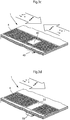
- the method is applied to a lateral flow assay, for example an assay performed on a platform as schematically shown in Figure 1 .
- This lateral flow assay platform or so called assay chip 1
- the flow path can comprise open or closed paths, grooves and/or capillaries.
- the flow path comprises a lateral flow path of adjacent projections, each having a size, shape and mutual spacing such that capillary flow is sustained through said flow path.
- Figure 1 also schematically indicates the position of one or more magnetic elements 6, either incorporated into the assay platform, or elements of a reader (not shown), which can be brought into operational contact with the assay chip1.
- the flow path is at least partially open. In another embodiment the flow path is entirely open.
- "Open" in accordance with this invention means that there is no lid or cover at a capillary distance. Thus the lid, if present as a physical protection for the flow path, does not contribute to the capillary flow in said flow path.
- An open lateral flow path is described for example in the following published applications: WO 2003/103835 , WO 2005/089082 ; WO 2005/118139 ; WO 2006/137785 ; and WO 2007/149042 . Details on the micro-pillars as well as their height, diameter and reciprocal spacing can be obtained from these documents.
- magnetic force is applied to the "open" side of the assay. Magnetic force is thus applied from above, or from the open side of the capillary structure.
- the magnetic particles concentrate under the liquid-air interface, without leaving the liquid phase. This allows qualitative and quantitative detection of the result from above, unencumbered by the substrate; i.e., without having to compensate for the influence of the substrate on signal strength, distortion etc.
- the inventors also make available an improved assay device for the detection of an analyte in a sample, said device comprising a sample addition zone, a reaction zone, and a sink, said zones forming a flow path; a first capture molecule, capable of binding to said analyte, optionally deposited on the device; and a second capture molecule also capable of binding to said analyte, optionally deposited on said device, wherein said first capture molecule carries a first label which is not a magnetic label, and said second capture molecule is attached to a magnetic particle.
- said magnetic particle preferably has a size in the interval of about 5 nm to about 5000 nm, more preferably about 50 to about 500 nm.
- Said second capture molecule and magnetic particle optionally also carries a second label, distinguishable from said first label.
- said second capture molecule is pre-deposited on said assay device.
- said first capture molecule is pre-deposited on said assay device.
- both said first and second capture molecules are pre-deposited on said assay device.
- both said first and said second capture molecules are deposited in said sample addition zone, and capable of being transported along said flow path upon addition of a sample to said sample addition zone.
- At least said sink consists of projections, substantially perpendicular to the surface of the device, and having a height, width, and reciprocal spacing such, that capillary flow is induced in the flow path.
- the flow path consists of micro-pillars being projections substantially vertical in relation to a surface, and having a height, diameter and reciprocal spacing capable of creating lateral flow of the sample in said flow path.
- a device according to the invention is schematically shown in Figures 3a-3d , where a section of the flow path or reaction zone 4 is shown in alternative views, each view illustrating a different embodiment of the invention, freely combinable with other embodiments.
- FIG. 3a shows schematic partial cross-section of an assay device or platform according to one embodiment in which conjugates comprising a capture molecule and a magnetic particle are manipulated using magnetic force, here illustrated as magnetic elements 20, 22, 24, 26, and 28 arranged or brought into operational distance from the assay device to influence the movement and/or position of the capture molecules bound to magnetic particles, or the detection complex, comprising magnetic particles.
- the magnetic elements 20, 22, 24, 26, and 28 can be brought into operational contact with the device, or activated, serially, in parallel, or in a desired sequence or pattern in order to influence the contact time between capture molecules and the sample, improve mixing and reaction kinetics. This can be achieved, for example, by mechanically moving a magnet, or by activating one or more electromagnets.
- the molecules bound to magnetic particles herein can also be both retarded and accelerated in relation to their movement in the absence of the magnetic force. Retarding the movement of a particle will make it move more slowly than the sample, and can prolong the contact time. Accelerating the particle can help to agitate the sample, also improving contact and kinetics of the reaction. Manipulating the particles also encompasses that the particles are moved in one, two or three directions, such as back and forth in relation to the flow of sample, transversally in relation to the flow of sample, or oscillated within the sample layer on the assay device.
- capture molecules or the entire detection complex, are moved to different locations on the assay device; e.g., returned to the sample addition zone for prolonged contact with the sample, circulated within the reaction zone for improved kinetics, or concentrated in a specific location for reading the result of the assay etc.
- FIG. 3b shows an embodiment of an assay device 1 according to another embodiment, having a flow path, here shown as part of the reaction zone 4, in which conjugates comprising a capture molecule and a magnetic particle are aided by a movable magnetic element 32 in bridging a gap or discontinuity 30 in the flow path, e.g. a portion without micropillars, a portion with reduced capillary flow, a time gate, etc.
- FIG. 3c shows another embodiment of an assay device 1 according to another embodiment, having a flow path; e.g., the reaction zone 4, where conjugates comprising a capture molecule and a magnetic particle are drawn by magnetic force to one or more specific, discrete locations on the assay platform; e.g., a section of the flow path, a location outside the flow path, or another location, for example in order to facilitate reading the result.
- a discrete location is here illustrated as an area 42 without micro-pillars within the flow path.
- An element 40 e.g., a permanent magnet or an electromagnet, is schematically shown in a position corresponding to the location of the area 42. This element can either be integrated in the assay device 1, or preferably part of a device for reading the result.
- Fig. 3d shows another embodiment of an assay device 1 having a flow path, e.g. the reaction zone 4, in which a stationary magnetic element 50 in association with a discontinuity 52 in the flow path, can function as a valve or time gate.
- the discontinuity in the flow path constitutes a discontinuity in the capillary force, and prevents the mixture of sample and capture molecules from advancing along the flow path under the influence of said capillary force.
- the capture molecules bound to magnetic particles, as well as detection complexes comprising magnetic particles are drawn into the discontinuity, wetting the opposite end of the flow path and restoring capillary flow.
- the assay device according to embodiments of the invention can also be applied to other formats and platforms, such as bibulous materials, e.g. nitrocellulose fiber based materials.
- An assay device according to embodiments of the invention can also be a reaction vessel, such as a well of a microtiter plate.
- the flow path comprises a nitrocellulose based material.
- the flow path is covered by a lid.
- Said lid preferably does not participate in the creation of capillary flow.
- the flow path comprises an area without micro-pillars within the reaction zone.
- an area without micro-pillars is provided adjacent to said flow path in fluid connection therewith.
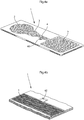
- Figure 4a shows an embodiment of a lateral flow assay platform, or so called assay chip 1, having a sample addition zone 2, a conjugate zone 3, a reaction zone 4, and a sink 5, forming a flow path between said sample addition zone and said sink, where a discrete location 60 is formed, here shown as an appendix to the main flow path, in fluid connection therewith.
- Figure 4b shows how the discrete location, here denoted 62 can be an appendix to the reaction zone 4 on an assay platform or chip 1.
- This area 62 is also in fluid connection with the flow path, but has however a different structure, here shown as an area without micro-pillars.
- the flow path preferably comprises at least one discrete area with micro-pillars having a different height, diameter or reciprocal spacing than the micro-pillars in the surrounding flow path.
- said device comprises magnetic elements.
- Said magnetic elements are, for example, permanent magnets, incorporated into the device.
- said magnetic elements are elements capable of generating a magnetic field when subjected to an external signal; e.g., the application of an electric current through said element.
- said device preferably comprises a discrete area in connection with the flow path, said area having features improving the reading of the result of the assay.
- the device is preferably a disposable assay device.
- said first and second capture molecule is preferably chosen from the group consisting of antibodies, antibody fragments, aptamers, and nucleic acid sequences, specific for the analyte to be detected.
- said first and/or second label is preferably a label chosen from chromophores, fluorophores, radioactive labels, and enzymes. Examples of labels are given above in the preceding description, and equally applicable in this context.
- the assay device and methods according to embodiments of the invention can also be applied to other assay formats and assay platforms, such as assays conducted on bibulous materials, such as nitrocellulose fiber based materials.
- the assay device and methods according to embodiments of the invention can also be applied to assays conducted in suspension, in reaction vessels, or at least partially bound to the walls of reaction vessels.
- the inventors also make available a device for reading (a reader) the result of an assay performed on an assay device (an assay platform), wherein said device comprises means for reading a signal emitted by, or reflected from said detection complex, means for computing the signal and displaying a result, and means capable of manipulating magnetic components present on said assay device.
- said means capable of manipulating magnetic components present on said assay device comprise one or more permanent magnets that can be brought in effective contact with or electromagnets activated within effective distance of the assay device or chip.
- said means capable of manipulating magnetic components present on said assay device are means for inducing a magnetic force, activating electromagnets or other elements present in the assay device.
- Examples of elements that can be activated include, but are not limited to, thermally activated magnetic elements, elements such as coils that are electrically activated, conducting elements that induce a magnetic field when subjected to an electric current, and Fe-based elements that are magnetized when in contact with an external magnet.
- said means capable of manipulating magnetic components present on said assay device are magnetic means which are part of a device for reading the results of the assay, and capable of being brought within an effective distance from the assay device for manipulating magnetic components present on the assay device.
- electromagnets are arranged in the reader at an effective distance to the assay device, or chip, when in position in the reader, and said electromagnets can then be activated when desired, in order to exert an influence on the magnetic particles in the capture conjugate or in the detection complex.
- said means capable of manipulating magnetic components present on said assay device may also comprise first means present in said device for reading the result (the reader), which activate second means, present in the assay device (the assay platform), which upon activation generate a magnetic field.
- Another embodiment is a device for reading the result of an assay performed on an assay device, wherein said device comprises a detector capable of reading a signal emitted from or reflected from at least one detection complex present in a defined location of said assay device, and means capable of drawing magnetic components present on said assay device to said location before reading said signal.
- said means are first means present in said device for reading the result, which activate second means, present in the assay device, which upon activation generate a magnetic field capable of drawing magnetic components present on said assay device to said location before reading said signal.
- the reading preferably is chosen from the detection and/or quantification of color, fluorescence, radioactivity or enzymatic activity.
- the advantage of using magnetic beads as the solid phase in a lateral flow assay was demonstrated in an analyte binding assay using a standard assay design for comparison i.e. where the capture antibody is bound to the flow path.
- the analyte used was C-reactive protein (CRP), a marker for inflammation and heart failure.
- CRP C-reactive protein
- the test was carried out on a non-porous carrier, having a micropillar array defining an open lateral flow path, as described for example in one of WO 2003/103835 , WO 2005/089082 ; WO 2005/118139 ; WO 2006/137785 ; and WO 2007/149042 .
- Plastic substrate chips made of Zeonor® Zeon Corporation, Japan
- the chips or assay devices were designed substantially as illustrated in Fig. 1 .
- An anti-CRP antibody M701189 (Fitzgerald, USA) was linked to paramagnetic beads of diameter 0,2 ⁇ m (Adembeads, Ademtech, France) in reaction buffer (25 mM MES buffer, pH 6.0) forming the product bead-aCRP.
- Carboxylated beads (4x10E11 particles) were incubated with 50 mg/ml 1-Ethyl-3-(3-dimethylaminopropyl) carbodiimide hydrochloride and 50 mg/ml Sulfo-N-hydroxyl succinimide ester for 30 min at room temperature, in a total volume of 100 ⁇ l reaction buffer.
- An analyte binding assay with respect to CRP was run in open lateral flow chips similar to the design shown in Figure 1 .
- the chip was placed in a chip holder with magnets (a stack of three 1mm thick 3x3mm block magnets, Neodym35, ELFA, Sweden) fixed in close proximity to the bottom surface of the chip, below the flow path.
- the chip holder was then placed in a humidity chamber. 5 ⁇ l of storage buffer was added before application of sample.
- Bead-antiCRP antibody as well as CRP* were diluted separately in serum (TSH free serum, US Biological), and a set of bead-antiCRP antibody dilutions were prepared.
- Each individual assay sample was prepared by mixing equal volumes of 20 ng/ml CRP* and bead-antiCRP antibody allowing 30 seconds of binding reaction before application of 10 ⁇ l mixture in the chip sample zone. Surplus reagents were removed by washing with three times 7.5 ⁇ l of serum. As control, the background signal generated by the beads themselves was recorded; i.e., no CRP* was added but bead-antiCRP antibody dilution was applied as sample.
- anti-CRP antibody containing chips were produced by deposition of 60 nl of 1.0 mg/ml antibody (in 50 mM Sodium phosphate buffer pH 7.5, 2% Trealose) by Biodot AD3200. The signal intensities were recorded in a prototype line-illuminating fluorescence scanner ( ⁇ mic AB, Sweden). The experiment was repeated several times, using different chip variants, and materials prepared and the experiments performed by different persons.
- Fig. 5 shows the results of an analyte binding assay of fluorophore labeled CRP binding to various concentrations of anti-CRP antibody linked to magnetic beads retarded by magnet. Empty symbols display beads mixed with CRP* and filled symbols indicate beads only. Thirty seconds of binding was allowed before application on the chip. The dashed line corresponds to binding of labeled CRP to anti-CRP antibody deposited in the chip path. Different symbols (squares, circles, triangles) in Fig. 5 indicate different runs, performed at the same concentration, but under different conditions (preparation, experimentalist and chip variant).
- Example 2 Experiments were performed with the same or similar chip design as in Example 1, using the same anti-CRP antibody and paramagnetic beads. Contrary to the procedure in Example 1, the magnets (a stack of three 1mm thick 3x3mm block magnets, Neodym35, ELFA, Sweden) were now held above the flow path, in close proximity to the chip. Surprisingly the beads did not leave the liquid phase, but instead accumulated just below the liquid surface. Without wishing to be bound by theory, the inventors speculate that the surface tension was sufficient to prevent the beads from leaving the liquid phase. The experiments showed that magnetic particles can be used in an open lateral flow system, and freely manipulated within the liquid phase, e.g. moved in any direction or even oscillated within the liquid phase.
- this embodiment makes it possible to concentrate the detection conjugates at the liquid-air-interface. This makes it possible to read the signal directly, from the side of the flow path, and not from below, through the substrate as frequently is the case. This in turn obviates problems with signal distortion, signal weakening, and other consequences of measuring through the substrate.
- extracting the detection conjugates from the flow path into the surface of the liquid phase can help to remove the conjugates from the physical structure of the flow path, regardless of this comprising fibers or microstructures, and draw the detection conjugates into a well defined, uniform and discrete location.
Claims (8)
- Procédé pour la détection d'un analyte dans un échantillon de liquide en utilisant un dispositif d'analyse à flux latéral ouvert (1) incluant au moins une zone d'ajout d'échantillon (2), au moins une zone de réaction (4), et au moins une dépression en surface (5) sur un substrat, lesdites zones formant un chemin de flux pour ledit échantillon sur ledit substrat ; une première molécule de capture sur ledit dispositif d'analyse, susceptible de se lier audit analyte ; et une seconde molécule de capture également susceptible de se lier audit analyte, dans lequel ladite première molécule de capture porte un premier marqueur qui n'est pas un marqueur magnétique, formant de ce fait un conjugué de détection, et ladite seconde molécule de capture est attachée à une particule magnétique, formant de ce fait un conjugué de capture, dans lequel le chemin de flux inclut des micro-piliers qui sont des projections sensiblement verticales par rapport à une surface, et ayant une hauteur, un diamètre et un espacement réciproque susceptibles de créer un flux latéral capillaire de l'échantillon dans ledit chemin de flux, et en outre dans lequel une force magnétique est appliquée au côté ouvert du chemin de flux, concentrant le conjugué de détection sur interface liquide / air.
- Procédé selon la revendication 1, incluant l'étape de dépôt préalable de ladite seconde molécule de capture attachée à ladite particule magnétique sur ledit dispositif d'analyse, et d'ajout de ladite première molécule de capture après ou simultanément avec l'ajout dudit échantillon.
- Procédé selon la revendication 1, incluant l'étape de dépôt préalable des deux dites première et seconde molécules de capture sur ledit dispositif d'analyse.
- Procédé selon la revendication 1, incluant l'étape de dépôt des deux dites première et seconde molécules de capture dans ladite zone d'ajout d'échantillon dans laquelle chacune desdites molécules de capture est transportée le long dudit chemin de flux lors de l'ajout d'un échantillon à ladite zone d'ajout d'échantillon, et de réaction avec l'analyte formant ainsi un complexe de détection constitué par ledit analyte, les première et seconde molécules de capture, et lesdits marqueur(s) et particule magnétique.
- Procédé selon la revendication 1, dans lequel ladite seconde molécule de capture et/ou ladite particule magnétique portent également un second marqueur, pouvant être distingué dudit premier marqueur.
- Procédé selon la revendication 1, dans lequel ledit échantillon est un échantillon pris auprès d'un mammifère, choisi parmi le sang, sérum, plasma, urine, salive, biopsies de tissu, selles, crachat et des frottis de gorge ou de peau.
- Procédé selon la revendication 1, dans lequel lesdites première et seconde molécules de capture sont choisies à partir du groupe constitué par des anticorps, des fragments d'anticorps, des aptamères et des séquences d'acides nucléiques, spécifiques pour l'analyte à détecter.
- Procédé selon la revendication 1, dans lequel ledit premier et/ou second marqueur est un marqueur choisi à partir de chromophores, fluorophores, marqueurs radioactifs, et enzymes.
Applications Claiming Priority (3)
| Application Number | Priority Date | Filing Date | Title |
|---|---|---|---|
| US25240009P | 2009-10-16 | 2009-10-16 | |
| SE0950762 | 2009-10-16 | ||
| PCT/EP2010/065600 WO2011045436A1 (fr) | 2009-10-16 | 2010-10-18 | Procédé et dispositifs d'analyse mettant en jeu l'utilisation de particules magnétiques |
Publications (2)
| Publication Number | Publication Date |
|---|---|
| EP2488871A1 EP2488871A1 (fr) | 2012-08-22 |
| EP2488871B1 true EP2488871B1 (fr) | 2017-01-04 |
Family
ID=43334528
Family Applications (1)
| Application Number | Title | Priority Date | Filing Date |
|---|---|---|---|
| EP10774160.5A Active EP2488871B1 (fr) | 2009-10-16 | 2010-10-18 | Procédé d'analyse mettant en jeu l'utilisation de particules magnétiques |
Country Status (6)
| Country | Link |
|---|---|
| EP (1) | EP2488871B1 (fr) |
| JP (2) | JP2013507633A (fr) |
| CN (1) | CN102753972B (fr) |
| CA (1) | CA2777807A1 (fr) |
| RU (1) | RU2595843C2 (fr) |
| WO (1) | WO2011045436A1 (fr) |
Families Citing this family (18)
| Publication number | Priority date | Publication date | Assignee | Title |
|---|---|---|---|---|
| JP6395999B2 (ja) | 2012-01-20 | 2018-09-26 | オーソ−クリニカル・ダイアグノスティックス・インコーポレイテッドOrtho−Clinical Diagnostics, Inc. | アッセイ装置を通じた流体流の制御 |
| ES2807902T3 (es) | 2012-08-21 | 2021-02-24 | Janssen Pharmaceutica Nv | Anticuerpos para olanzapina y uso de los mismos |
| CN109400708A (zh) | 2012-08-21 | 2019-03-01 | 詹森药业有限公司 | 奥氮平半抗原的抗体及其用途 |
| CN105102979B (zh) | 2013-01-29 | 2017-05-03 | 生物辐射海法有限公司 | 利用磁性纳米粒子的检测测定法 |
| KR102435654B1 (ko) * | 2013-03-11 | 2022-08-25 | 큐 헬스 인코퍼레이티드 | 분석물의 검출 및 정량을 위한 시스템 및 방법 |
| CN103308671B (zh) * | 2013-05-22 | 2016-02-03 | 北京康彻思坦生物技术有限公司 | 一种检测膜及检测系统 |
| CN103323603A (zh) * | 2013-06-07 | 2013-09-25 | 博奥生物有限公司 | 一种在磁珠表面共价偶联蛋白质的方法 |
| US9784736B2 (en) * | 2013-06-28 | 2017-10-10 | Danmarks Tekniske Universitet | Biosensor based on measurements of the clustering dynamics of magnetic particles |
| JP6278772B2 (ja) * | 2014-03-19 | 2018-02-14 | テルモ株式会社 | 血糖値測定用チップ |
| JP6466775B2 (ja) | 2015-04-30 | 2019-02-06 | シスメックス株式会社 | 検体分析カートリッジを用いた検体分析方法、検体分析カートリッジ、および、検体分析装置 |
| CN107636461B (zh) * | 2015-05-13 | 2019-09-20 | Sls生物科技有限公司 | 利用多个金属纳米标签的多个靶标的同时分析方法 |
| CN105424922B (zh) * | 2015-12-09 | 2018-01-19 | 北京乐普医疗科技有限责任公司 | 基于磁珠包被抗体的微流控芯片及捕获心肌标志物的方法 |
| KR20190127665A (ko) * | 2017-03-28 | 2019-11-13 | 덴카 주식회사 | 막 담체와 이를 이용한 액체 시료 검사 키트 및 그 제조 방법 |
| US11561197B2 (en) | 2018-06-29 | 2023-01-24 | AMMR Joint Venture | Electronic detection of a target based on enzymatic cleavage of a reporter moiety |
| WO2020026210A1 (fr) * | 2018-08-03 | 2020-02-06 | National Research Council Of Canada | Distribution de nanoparticules magnétiques dans une puce microfluidique |
| GB201818412D0 (en) * | 2018-11-12 | 2018-12-26 | Lumiradx Tech Ltd | A magnetic assembly for use in a device for conducting assays |
| US20220395834A1 (en) * | 2019-11-15 | 2022-12-15 | Redbud Labs, Inc. | Microfluidic device for and methods of using surface-attached posts and capture beads in a microfluidic chamber |
| WO2023141199A2 (fr) * | 2022-01-21 | 2023-07-27 | Trustees Of Dartmouth College | Formation de motifs par microtransfert de matériaux magnétiques pour des applications microfluidiques |
Citations (7)
| Publication number | Priority date | Publication date | Assignee | Title |
|---|---|---|---|---|
| WO2003103835A1 (fr) * | 2002-06-07 | 2003-12-18 | Åmic AB | Structures microfluidiques |
| WO2005089082A2 (fr) * | 2004-03-24 | 2005-09-29 | Åmic AB | Dispositif et procede de dosage |
| WO2005118139A1 (fr) * | 2004-06-02 | 2005-12-15 | Åmic AB | Dispositif et procede de dosage a ecoulement regule |
| WO2006137785A1 (fr) * | 2005-06-20 | 2006-12-28 | Åmic AB | Procede et moyens de creation d'un transport de liquide |
| WO2007110779A2 (fr) * | 2006-03-29 | 2007-10-04 | Inverness Medical Switzerland Gmbh | Dispositif de dosage et procede |
| WO2007149042A1 (fr) * | 2006-06-20 | 2007-12-27 | Åmic AB | Dispositif et procédé de dosage |
| WO2007149043A1 (fr) * | 2006-06-20 | 2007-12-27 | Åmic AB | dispositif de test |
Family Cites Families (14)
| Publication number | Priority date | Publication date | Assignee | Title |
|---|---|---|---|---|
| EP0963554B1 (fr) * | 1997-01-30 | 2002-10-23 | MERCK PATENT GmbH | Procede de detection immunologique d'un analyte |
| US6136549A (en) * | 1999-10-15 | 2000-10-24 | Feistel; Christopher C. | systems and methods for performing magnetic chromatography assays |
| US6607922B2 (en) * | 2000-03-17 | 2003-08-19 | Quantum Design, Inc. | Immunochromatographic assay method and apparatus |
| US7018849B2 (en) * | 2002-01-15 | 2006-03-28 | Piasio Roger N | Process for (A) separating biological/ligands from dilute solutions and (B) conducting an immunochromatographic assay thereof employing superparamagnetic particles throughtout |
| CN100405063C (zh) * | 2003-09-30 | 2008-07-23 | 江西中德生物工程有限公司 | 桔霉素免疫层析检测试纸及其制作方法与应用 |
| CN100334105C (zh) * | 2003-12-12 | 2007-08-29 | 上海交通大学 | 纳米磁性颗粒分离纯化链酶亲合素的方法 |
| CN100389327C (zh) * | 2004-06-22 | 2008-05-21 | 北京倍爱康生物技术股份有限公司 | 一种甲状腺过氧化物酶抗体磁分离酶联免疫检测方法 |
| JP4791867B2 (ja) * | 2005-03-31 | 2011-10-12 | 日立マクセル株式会社 | 貴金属コート磁性粒子を用いた被検物質の検出方法 |
| WO2006134546A2 (fr) | 2005-06-17 | 2006-12-21 | Koninklijke Philips Electronics N.V. | Biocapteur magnetique precis |
| CN101438142B (zh) | 2006-05-10 | 2013-10-30 | 皇家飞利浦电子股份有限公司 | 快速磁生物传感器 |
| US8409877B2 (en) | 2006-12-29 | 2013-04-02 | Intel Corporation | Enzymatic signal generation and detection of binding complexes in stationary fluidic chip |
| CN201087839Y (zh) * | 2007-03-30 | 2008-07-16 | 万华普曼生物工程有限公司 | 脑钠肽颜色颗粒诊断试纸 |
| US8658093B2 (en) | 2007-07-06 | 2014-02-25 | Applied Biosystems, Llc | Devices and methods for the detection of analytes |
| CN101315382B (zh) * | 2008-07-18 | 2012-12-05 | 中国检验检疫科学研究院 | 用于检测卡那霉素残留的免疫胶体金试纸条及其制备方法 |
-
2010
- 2010-10-18 EP EP10774160.5A patent/EP2488871B1/fr active Active
- 2010-10-18 WO PCT/EP2010/065600 patent/WO2011045436A1/fr active Application Filing
- 2010-10-18 JP JP2012533652A patent/JP2013507633A/ja active Pending
- 2010-10-18 CN CN201080057103.1A patent/CN102753972B/zh active Active
- 2010-10-18 CA CA2777807A patent/CA2777807A1/fr not_active Abandoned
- 2010-10-18 RU RU2012120104/15A patent/RU2595843C2/ru not_active IP Right Cessation
-
2015
- 2015-09-17 JP JP2015183870A patent/JP6158266B2/ja active Active
Patent Citations (7)
| Publication number | Priority date | Publication date | Assignee | Title |
|---|---|---|---|---|
| WO2003103835A1 (fr) * | 2002-06-07 | 2003-12-18 | Åmic AB | Structures microfluidiques |
| WO2005089082A2 (fr) * | 2004-03-24 | 2005-09-29 | Åmic AB | Dispositif et procede de dosage |
| WO2005118139A1 (fr) * | 2004-06-02 | 2005-12-15 | Åmic AB | Dispositif et procede de dosage a ecoulement regule |
| WO2006137785A1 (fr) * | 2005-06-20 | 2006-12-28 | Åmic AB | Procede et moyens de creation d'un transport de liquide |
| WO2007110779A2 (fr) * | 2006-03-29 | 2007-10-04 | Inverness Medical Switzerland Gmbh | Dispositif de dosage et procede |
| WO2007149042A1 (fr) * | 2006-06-20 | 2007-12-27 | Åmic AB | Dispositif et procédé de dosage |
| WO2007149043A1 (fr) * | 2006-06-20 | 2007-12-27 | Åmic AB | dispositif de test |
Also Published As
| Publication number | Publication date |
|---|---|
| CN102753972B (zh) | 2016-01-13 |
| RU2012120104A (ru) | 2013-11-27 |
| RU2595843C2 (ru) | 2016-08-27 |
| CN102753972A (zh) | 2012-10-24 |
| EP2488871A1 (fr) | 2012-08-22 |
| JP2016035465A (ja) | 2016-03-17 |
| JP2013507633A (ja) | 2013-03-04 |
| CA2777807A1 (fr) | 2011-04-21 |
| JP6158266B2 (ja) | 2017-07-05 |
| WO2011045436A1 (fr) | 2011-04-21 |
Similar Documents
| Publication | Publication Date | Title |
|---|---|---|
| EP2488871B1 (fr) | Procédé d'analyse mettant en jeu l'utilisation de particules magnétiques | |
| US10006907B2 (en) | Cartridge for assays with magnetic particles | |
| US9575081B2 (en) | Device and methods for detecting analytes in saliva | |
| US5741714A (en) | Detection of bound analyte by magnetic partitioning and masking | |
| US20030040129A1 (en) | Binding assays using magnetically immobilized arrays | |
| US20100311186A1 (en) | Devices and methods for performing receptor binding assays using magnetic particles | |
| US20070166835A1 (en) | Multiplex assays using magnetic and non-magnetic particles | |
| CA2589071C (fr) | Dosage par formation de liaisons base sur des particules | |
| US20130122517A1 (en) | Method of performing an assay | |
| US9823241B2 (en) | Processing of a sample fluid with target components | |
| JPH0580052A (ja) | 生体内物質の測定装置及び測定方法 | |
| JPH09229936A (ja) | 磁性粒子を用いる被検物質の測定方法並びに該方法に使用する担体及び測定器具 | |
| KR102220357B1 (ko) | 면역진단 키트 및 이를 이용한 면역진단 방법 | |
| BR112012008950A2 (pt) | método de ensaio e dispositivo que envolvem o uso de partículas magnéticas | |
| JPH11326327A (ja) | 粒子を使用する被検物質の測定方法及び測定器具 | |
| US20040005627A1 (en) | Microvolume detecting method and device |
Legal Events
| Date | Code | Title | Description |
|---|---|---|---|
| PUAI | Public reference made under article 153(3) epc to a published international application that has entered the european phase |
Free format text: ORIGINAL CODE: 0009012 |
|
| 17P | Request for examination filed |
Effective date: 20120419 |
|
| AK | Designated contracting states |
Kind code of ref document: A1 Designated state(s): AL AT BE BG CH CY CZ DE DK EE ES FI FR GB GR HR HU IE IS IT LI LT LU LV MC MK MT NL NO PL PT RO RS SE SI SK SM TR |
|
| DAX | Request for extension of the european patent (deleted) | ||
| 17Q | First examination report despatched |
Effective date: 20141205 |
|
| GRAP | Despatch of communication of intention to grant a patent |
Free format text: ORIGINAL CODE: EPIDOSNIGR1 |
|
| INTG | Intention to grant announced |
Effective date: 20160621 |
|
| GRAS | Grant fee paid |
Free format text: ORIGINAL CODE: EPIDOSNIGR3 |
|
| GRAA | (expected) grant |
Free format text: ORIGINAL CODE: 0009210 |
|
| AK | Designated contracting states |
Kind code of ref document: B1 Designated state(s): AL AT BE BG CH CY CZ DE DK EE ES FI FR GB GR HR HU IE IS IT LI LT LU LV MC MK MT NL NO PL PT RO RS SE SI SK SM TR |
|
| REG | Reference to a national code |
Ref country code: GB Ref legal event code: FG4D |
|
| REG | Reference to a national code |
Ref country code: CH Ref legal event code: EP |
|
| REG | Reference to a national code |
Ref country code: AT Ref legal event code: REF Ref document number: 859747 Country of ref document: AT Kind code of ref document: T Effective date: 20170115 |
|
| REG | Reference to a national code |
Ref country code: IE Ref legal event code: FG4D |
|
| REG | Reference to a national code |
Ref country code: DE Ref legal event code: R096 Ref document number: 602010039343 Country of ref document: DE |
|
| REG | Reference to a national code |
Ref country code: SE Ref legal event code: TRGR |
|
| REG | Reference to a national code |
Ref country code: LT Ref legal event code: MG4D Ref country code: NL Ref legal event code: MP Effective date: 20170104 |
|
| REG | Reference to a national code |
Ref country code: AT Ref legal event code: MK05 Ref document number: 859747 Country of ref document: AT Kind code of ref document: T Effective date: 20170104 |
|
| PG25 | Lapsed in a contracting state [announced via postgrant information from national office to epo] |
Ref country code: NL Free format text: LAPSE BECAUSE OF FAILURE TO SUBMIT A TRANSLATION OF THE DESCRIPTION OR TO PAY THE FEE WITHIN THE PRESCRIBED TIME-LIMIT Effective date: 20170104 |
|
| PG25 | Lapsed in a contracting state [announced via postgrant information from national office to epo] |
Ref country code: LT Free format text: LAPSE BECAUSE OF FAILURE TO SUBMIT A TRANSLATION OF THE DESCRIPTION OR TO PAY THE FEE WITHIN THE PRESCRIBED TIME-LIMIT Effective date: 20170104 Ref country code: GR Free format text: LAPSE BECAUSE OF FAILURE TO SUBMIT A TRANSLATION OF THE DESCRIPTION OR TO PAY THE FEE WITHIN THE PRESCRIBED TIME-LIMIT Effective date: 20170405 Ref country code: HR Free format text: LAPSE BECAUSE OF FAILURE TO SUBMIT A TRANSLATION OF THE DESCRIPTION OR TO PAY THE FEE WITHIN THE PRESCRIBED TIME-LIMIT Effective date: 20170104 Ref country code: IS Free format text: LAPSE BECAUSE OF FAILURE TO SUBMIT A TRANSLATION OF THE DESCRIPTION OR TO PAY THE FEE WITHIN THE PRESCRIBED TIME-LIMIT Effective date: 20170504 Ref country code: FI Free format text: LAPSE BECAUSE OF FAILURE TO SUBMIT A TRANSLATION OF THE DESCRIPTION OR TO PAY THE FEE WITHIN THE PRESCRIBED TIME-LIMIT Effective date: 20170104 Ref country code: NO Free format text: LAPSE BECAUSE OF FAILURE TO SUBMIT A TRANSLATION OF THE DESCRIPTION OR TO PAY THE FEE WITHIN THE PRESCRIBED TIME-LIMIT Effective date: 20170404 |
|
| PG25 | Lapsed in a contracting state [announced via postgrant information from national office to epo] |
Ref country code: RS Free format text: LAPSE BECAUSE OF FAILURE TO SUBMIT A TRANSLATION OF THE DESCRIPTION OR TO PAY THE FEE WITHIN THE PRESCRIBED TIME-LIMIT Effective date: 20170104 Ref country code: AT Free format text: LAPSE BECAUSE OF FAILURE TO SUBMIT A TRANSLATION OF THE DESCRIPTION OR TO PAY THE FEE WITHIN THE PRESCRIBED TIME-LIMIT Effective date: 20170104 Ref country code: PL Free format text: LAPSE BECAUSE OF FAILURE TO SUBMIT A TRANSLATION OF THE DESCRIPTION OR TO PAY THE FEE WITHIN THE PRESCRIBED TIME-LIMIT Effective date: 20170104 Ref country code: BG Free format text: LAPSE BECAUSE OF FAILURE TO SUBMIT A TRANSLATION OF THE DESCRIPTION OR TO PAY THE FEE WITHIN THE PRESCRIBED TIME-LIMIT Effective date: 20170404 Ref country code: LV Free format text: LAPSE BECAUSE OF FAILURE TO SUBMIT A TRANSLATION OF THE DESCRIPTION OR TO PAY THE FEE WITHIN THE PRESCRIBED TIME-LIMIT Effective date: 20170104 Ref country code: ES Free format text: LAPSE BECAUSE OF FAILURE TO SUBMIT A TRANSLATION OF THE DESCRIPTION OR TO PAY THE FEE WITHIN THE PRESCRIBED TIME-LIMIT Effective date: 20170104 Ref country code: PT Free format text: LAPSE BECAUSE OF FAILURE TO SUBMIT A TRANSLATION OF THE DESCRIPTION OR TO PAY THE FEE WITHIN THE PRESCRIBED TIME-LIMIT Effective date: 20170504 |
|
| REG | Reference to a national code |
Ref country code: FR Ref legal event code: PLFP Year of fee payment: 8 |
|
| REG | Reference to a national code |
Ref country code: DE Ref legal event code: R097 Ref document number: 602010039343 Country of ref document: DE |
|
| PG25 | Lapsed in a contracting state [announced via postgrant information from national office to epo] |
Ref country code: EE Free format text: LAPSE BECAUSE OF FAILURE TO SUBMIT A TRANSLATION OF THE DESCRIPTION OR TO PAY THE FEE WITHIN THE PRESCRIBED TIME-LIMIT Effective date: 20170104 Ref country code: RO Free format text: LAPSE BECAUSE OF FAILURE TO SUBMIT A TRANSLATION OF THE DESCRIPTION OR TO PAY THE FEE WITHIN THE PRESCRIBED TIME-LIMIT Effective date: 20170104 Ref country code: SK Free format text: LAPSE BECAUSE OF FAILURE TO SUBMIT A TRANSLATION OF THE DESCRIPTION OR TO PAY THE FEE WITHIN THE PRESCRIBED TIME-LIMIT Effective date: 20170104 Ref country code: CZ Free format text: LAPSE BECAUSE OF FAILURE TO SUBMIT A TRANSLATION OF THE DESCRIPTION OR TO PAY THE FEE WITHIN THE PRESCRIBED TIME-LIMIT Effective date: 20170104 |
|
| PLBE | No opposition filed within time limit |
Free format text: ORIGINAL CODE: 0009261 |
|
| STAA | Information on the status of an ep patent application or granted ep patent |
Free format text: STATUS: NO OPPOSITION FILED WITHIN TIME LIMIT |
|
| PG25 | Lapsed in a contracting state [announced via postgrant information from national office to epo] |
Ref country code: DK Free format text: LAPSE BECAUSE OF FAILURE TO SUBMIT A TRANSLATION OF THE DESCRIPTION OR TO PAY THE FEE WITHIN THE PRESCRIBED TIME-LIMIT Effective date: 20170104 Ref country code: SM Free format text: LAPSE BECAUSE OF FAILURE TO SUBMIT A TRANSLATION OF THE DESCRIPTION OR TO PAY THE FEE WITHIN THE PRESCRIBED TIME-LIMIT Effective date: 20170104 |
|
| 26N | No opposition filed |
Effective date: 20171005 |
|
| PG25 | Lapsed in a contracting state [announced via postgrant information from national office to epo] |
Ref country code: SI Free format text: LAPSE BECAUSE OF FAILURE TO SUBMIT A TRANSLATION OF THE DESCRIPTION OR TO PAY THE FEE WITHIN THE PRESCRIBED TIME-LIMIT Effective date: 20170104 |
|
| PG25 | Lapsed in a contracting state [announced via postgrant information from national office to epo] |
Ref country code: MC Free format text: LAPSE BECAUSE OF FAILURE TO SUBMIT A TRANSLATION OF THE DESCRIPTION OR TO PAY THE FEE WITHIN THE PRESCRIBED TIME-LIMIT Effective date: 20170104 |
|
| PG25 | Lapsed in a contracting state [announced via postgrant information from national office to epo] |
Ref country code: LU Free format text: LAPSE BECAUSE OF NON-PAYMENT OF DUE FEES Effective date: 20171018 |
|
| REG | Reference to a national code |
Ref country code: BE Ref legal event code: MM Effective date: 20171031 |
|
| PG25 | Lapsed in a contracting state [announced via postgrant information from national office to epo] |
Ref country code: BE Free format text: LAPSE BECAUSE OF NON-PAYMENT OF DUE FEES Effective date: 20171031 |
|
| REG | Reference to a national code |
Ref country code: FR Ref legal event code: PLFP Year of fee payment: 9 |
|
| REG | Reference to a national code |
Ref country code: CH Ref legal event code: NV Representative=s name: GEVERS SA, CH Ref country code: CH Ref legal event code: PUE Owner name: CRIMSON INTERNATIONAL ASSETS LLC, US Free format text: FORMER OWNER: AMIC AB, SE |
|
| PG25 | Lapsed in a contracting state [announced via postgrant information from national office to epo] |
Ref country code: MT Free format text: LAPSE BECAUSE OF NON-PAYMENT OF DUE FEES Effective date: 20171018 |
|
| REG | Reference to a national code |
Ref country code: GB Ref legal event code: 732E Free format text: REGISTERED BETWEEN 20180920 AND 20180926 |
|
| REG | Reference to a national code |
Ref country code: DE Ref legal event code: R081 Ref document number: 602010039343 Country of ref document: DE Owner name: CRIMSON INTERNATIONAL ASSETS LLC, WILMINGTON, US Free format text: FORMER OWNER: AMIC AB, UPPSALA, SE |
|
| REG | Reference to a national code |
Ref country code: CH Ref legal event code: NV Representative=s name: BOVARD SA NEUCHATEL CONSEILS EN PROPRIETE INTE, CH |
|
| PG25 | Lapsed in a contracting state [announced via postgrant information from national office to epo] |
Ref country code: HU Free format text: LAPSE BECAUSE OF FAILURE TO SUBMIT A TRANSLATION OF THE DESCRIPTION OR TO PAY THE FEE WITHIN THE PRESCRIBED TIME-LIMIT; INVALID AB INITIO Effective date: 20101018 |
|
| PG25 | Lapsed in a contracting state [announced via postgrant information from national office to epo] |
Ref country code: CY Free format text: LAPSE BECAUSE OF NON-PAYMENT OF DUE FEES Effective date: 20170104 |
|
| PG25 | Lapsed in a contracting state [announced via postgrant information from national office to epo] |
Ref country code: MK Free format text: LAPSE BECAUSE OF FAILURE TO SUBMIT A TRANSLATION OF THE DESCRIPTION OR TO PAY THE FEE WITHIN THE PRESCRIBED TIME-LIMIT Effective date: 20170104 |
|
| PG25 | Lapsed in a contracting state [announced via postgrant information from national office to epo] |
Ref country code: TR Free format text: LAPSE BECAUSE OF FAILURE TO SUBMIT A TRANSLATION OF THE DESCRIPTION OR TO PAY THE FEE WITHIN THE PRESCRIBED TIME-LIMIT Effective date: 20170104 |
|
| PG25 | Lapsed in a contracting state [announced via postgrant information from national office to epo] |
Ref country code: AL Free format text: LAPSE BECAUSE OF FAILURE TO SUBMIT A TRANSLATION OF THE DESCRIPTION OR TO PAY THE FEE WITHIN THE PRESCRIBED TIME-LIMIT Effective date: 20170104 |
|
| PGFP | Annual fee paid to national office [announced via postgrant information from national office to epo] |
Ref country code: SE Payment date: 20201012 Year of fee payment: 11 |
|
| REG | Reference to a national code |
Ref country code: SE Ref legal event code: EUG |
|
| PG25 | Lapsed in a contracting state [announced via postgrant information from national office to epo] |
Ref country code: SE Free format text: LAPSE BECAUSE OF NON-PAYMENT OF DUE FEES Effective date: 20211019 |
|
| P01 | Opt-out of the competence of the unified patent court (upc) registered |
Effective date: 20230602 |
|
| PGFP | Annual fee paid to national office [announced via postgrant information from national office to epo] |
Ref country code: IT Payment date: 20230913 Year of fee payment: 14 Ref country code: IE Payment date: 20230912 Year of fee payment: 14 Ref country code: GB Payment date: 20230831 Year of fee payment: 14 |
|
| PGFP | Annual fee paid to national office [announced via postgrant information from national office to epo] |
Ref country code: FR Payment date: 20230911 Year of fee payment: 14 |
|
| PGFP | Annual fee paid to national office [announced via postgrant information from national office to epo] |
Ref country code: DE Payment date: 20230830 Year of fee payment: 14 Ref country code: CH Payment date: 20231102 Year of fee payment: 14 |