EP2487808B1 - Drahtloses kommunikationssystem, funkrelaisstationsvorrichtung, funkendgerätestationsvorrichtung und drahtloses kommunikationsverfahren - Google Patents
Drahtloses kommunikationssystem, funkrelaisstationsvorrichtung, funkendgerätestationsvorrichtung und drahtloses kommunikationsverfahren Download PDFInfo
- Publication number
- EP2487808B1 EP2487808B1 EP10821901.5A EP10821901A EP2487808B1 EP 2487808 B1 EP2487808 B1 EP 2487808B1 EP 10821901 A EP10821901 A EP 10821901A EP 2487808 B1 EP2487808 B1 EP 2487808B1
- Authority
- EP
- European Patent Office
- Prior art keywords
- packet
- error correction
- bit
- station apparatus
- circuit
- Prior art date
- Legal status (The legal status is an assumption and is not a legal conclusion. Google has not performed a legal analysis and makes no representation as to the accuracy of the status listed.)
- Active
Links
Images





Classifications
-
- H—ELECTRICITY
- H04—ELECTRIC COMMUNICATION TECHNIQUE
- H04L—TRANSMISSION OF DIGITAL INFORMATION, e.g. TELEGRAPHIC COMMUNICATION
- H04L1/00—Arrangements for detecting or preventing errors in the information received
-
- H—ELECTRICITY
- H04—ELECTRIC COMMUNICATION TECHNIQUE
- H04B—TRANSMISSION
- H04B7/00—Radio transmission systems, i.e. using radiation field
- H04B7/14—Relay systems
- H04B7/15—Active relay systems
- H04B7/155—Ground-based stations
- H04B7/15521—Ground-based stations combining by calculations packets received from different stations before transmitting the combined packets as part of network coding
-
- H—ELECTRICITY
- H04—ELECTRIC COMMUNICATION TECHNIQUE
- H04B—TRANSMISSION
- H04B7/00—Radio transmission systems, i.e. using radiation field
- H04B7/14—Relay systems
-
- H—ELECTRICITY
- H04—ELECTRIC COMMUNICATION TECHNIQUE
- H04L—TRANSMISSION OF DIGITAL INFORMATION, e.g. TELEGRAPHIC COMMUNICATION
- H04L1/00—Arrangements for detecting or preventing errors in the information received
- H04L1/0001—Systems modifying transmission characteristics according to link quality, e.g. power backoff
- H04L1/0009—Systems modifying transmission characteristics according to link quality, e.g. power backoff by adapting the channel coding
-
- H—ELECTRICITY
- H04—ELECTRIC COMMUNICATION TECHNIQUE
- H04L—TRANSMISSION OF DIGITAL INFORMATION, e.g. TELEGRAPHIC COMMUNICATION
- H04L1/00—Arrangements for detecting or preventing errors in the information received
- H04L1/004—Arrangements for detecting or preventing errors in the information received by using forward error control
- H04L1/0076—Distributed coding, e.g. network coding, involving channel coding
-
- H—ELECTRICITY
- H04—ELECTRIC COMMUNICATION TECHNIQUE
- H04L—TRANSMISSION OF DIGITAL INFORMATION, e.g. TELEGRAPHIC COMMUNICATION
- H04L1/00—Arrangements for detecting or preventing errors in the information received
- H04L2001/0092—Error control systems characterised by the topology of the transmission link
- H04L2001/0097—Relays
Definitions
- the present invention relates to a wireless communication system which employs network coding, a wireless relay station apparatus, a wireless terminal station apparatus, and a wireless communication method.
- the wireless relay station apparatus demodulates the packets of the respective communication flows into bit signals, performs network coding (NC) on sequences of the demodulated bit signals, and collectively transmits the sequences of the network coded bit signals to a wireless communication apparatus of a destination station (Non-patent Documents 1 and 2).
- the network coding indicates coding for superposing the packets of the respective communication flows through linear coding based on a predetermined generating formula.
- the wireless communication apparatus of the destination station performs linear decoding based on the generating formula on a packet of a relayed signal received from the wireless relay station apparatus, thereby acquiring a desired packet.
- the wireless relay station apparatus superposes the packets of the plurality of communication flows and performs a relay function by collectively transmitting the superposed packets, so that it is possible to reduce the number of transmissions of the wireless relay station apparatus and to shorten the time until the communication of the wireless communication system is completed. As a result, it is possible to improve the throughput of the wireless communication system.
- NC decoding performing the network coding on a packet
- NC decoding performing the network coding on a packet
- NC technology is applied to Alice-and-Bob topology, which is the topology of the simplest multi-hop communication
- XOR bitwise exclusive OR
- a network coded packet is defined as an NC packet
- a packet before network coding and a non-network-coded packet are defined as a native packet.
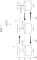
- FIG. 9A is a diagram illustrating the configuration of the wireless communication system 900.
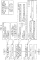
- FIG. 9B is a flowchart illustrating a process of a wireless relay station apparatus 93 provided in the wireless communication system 900.
- A denotes a signal which is transmitted from a wireless terminal station apparatus 91 (Node 1) at a time T1
- B denotes a signal which is transmitted from a wireless terminal station apparatus 92 (Node 3) at a time T2
- A+B denotes a signal which is transmitted from the wireless relay station apparatus 93 (Node 2) at a time T3.
- FIG. 9A is a diagram illustrating the outline of communication in the wireless communication system 900 with the Alice-and-Bob topology.
- the wireless terminal station apparatuses 91 and 92 (Nodes 1 and 3) arranged at both ends perform bi-directional communication therebetween through the wireless relay station apparatus 93 (Node 2).
- the following description will be given on the assumption that transmission of each node is performed at a predetermined time slot, and signals transmitted from the respective nodes do not interfere with one another.
- FIG. 9B is a flowchart illustrating a relay process of the wireless relay station apparatus 93.
- the size of a packet A transmitted from the wireless terminal station apparatus 91 is 1000 bytes and the size of a packet B transmitted from the wireless terminal station apparatus 92 is 700 bytes.
- a description will be given of the case in which a coding rate R A of the packet A and a coding rate R B of the packet B that are required for satisfying predetermined communication quality are 2/3 and 1/2, respectively.
- a packet corresponds to information to be transmitted
- a modulation symbol corresponds to a signal obtained by modulating (mapping) a bit signal included in a packet or the like in a baseband
- an RF (Radio Frequency) signal corresponds to a signal obtained by up-converting the modulation symbol into an RF band.
- the wireless terminal station apparatus 91 transmits an RF signal A of the packet A to the wireless relay station apparatus 93 and stores the packet A.
- the wireless relay station apparatus 93 receives the RF signal A transmitted by the wireless terminal station apparatus 91, and stores a packet A obtained by decoding the received RF signal A.
- the wireless terminal station apparatus 92 transmits an RF signal B of the packet B to the wireless relay station apparatus 93 and stores the packet B.
- the wireless relay station apparatus 93 receives the RF signal B transmitted by the wireless terminal station apparatus 92, and stores a packet B obtained by decoding the received RF signal B (step S901).
- the wireless relay station apparatus 93 compares a packet length L A (1000 bytes) with a packet length L B (700 bytes), appends zero padding with a data length of
- the wireless relay station apparatus 93 performs NC encoding on the packet A and the packet B through XOR to generate one NC packet C (step S903), and performs error correction encoding with a coding rate of 1/2 on the generated NC packet C (step S904).
- the wireless relay station apparatus 93 performs multicast transmission of an RF signal C to the wireless terminal station apparatuses 91 and 92 (steps S905 and S906), wherein the RF signal C is obtained by modulating and up-converting the error correction encoded NC packet C.
- a plurality of wireless terminal station apparatuses are designated as destination stations in header information, so that the same information is simultaneously transmitted to the plurality of destination stations using the multicast property of wireless communication. Furthermore, the packet lengths of the packet A and the packet B are included in the header information together with information indicating the destination stations.
- the wireless terminal station apparatuses 91 and 92 acquire the packet lengths from the header information of the received RF signal C.
- the wireless terminal station apparatus 91 Upon receipt of the RF signal C transmitted from the wireless relay station apparatus 93, the wireless terminal station apparatus 91 adjusts an output level through AGC (Auto Gain Control) using the received RF signal C, and down-converts and demodulates the received RF signal C to acquire an NC packet C.
- AGC Automatic Gain Control
- the wireless terminal station apparatus 91 performs zero padding corresponding to the difference between two packet lengths on the packet A to allow the packet length of the zero-padded packet A to coincide with the packet length of the NC packet C, and performs NC decoding through an XOR operation on the zero-padded packet A and the NC packet C to acquire a packet B.
- the wireless terminal station apparatus 91 performs NC decoding through an XOR operation on the NC packet C and the packet A. Then, the wireless terminal station apparatus 91 acquires the packet B from a packet obtained by the NC decoding based on the packet length of the packet B included in the header information.
- the wireless terminal station apparatus 92 also demodulates the NC packet C from the RF signal C.
- the wireless terminal station apparatus 92 performs zero padding corresponding to the difference between two packet lengths on the packet B so that the packet length of the zero-padded packet B coincides with the packet length of the NC packet C, and performs NC decoding through an XOR operation to acquire a packet A.
- the wireless terminal station apparatus 92 performs NC decoding through an XOR operation on the NC packet C and the packet B. Then, the wireless terminal station apparatus 92 acquires the packet A by deleting a portion appended through the zero padding from a packet obtained by the NC decoding based on the packet length of the packet A included in the header information.
- the wireless relay station apparatus 93 collectively performs multicast transmission of the packets received from the wireless terminal station apparatuses 91 and 92, thereby transmitting the packet B to the wireless terminal station apparatus 91 and transmitting the packet A to the wireless terminal station apparatus 92 using three time slots reduced by one time slot, as compared with the case in which packets are individually relayed.
- Document WO 2006/071187 A2 discloses methods and arrangements in a relaying radio node and/or in a sending/receiving radio node, adapted for use in a relaying communication system.
- the relaying node is in bidirectional communication with at least a first and a second sending/receiving radio node, and the relaying radio node receives at least a first signal carrying at least first data and a second signal carrying at least second data.
- the relaying node generates a reduced representation of at least the first and second signal, with a reduced information content as compared to the first and second data, by a joint nonlinearly encoding operation, and transmits the reduced representation to at least the first and the second communication node.
- the first and second sending/receiving node can extract data from the reduced representation by a non-linear decoding operation using stored a priori information.
- the network coding performs a process in which the zero padding is performed on information bit sequences of the native packets so as to allow the packet lengths of the native packets to coincide with each other.
- bit(s) are appended to the other native packets with relatively short packet lengths through the zero padding, thereby allowing the packet lengths to coincide with each other.
- the NC encoding is performed on the information bit sequences of the native packets with the same packet length, and the error correction (FEC) encoding is performed on the information bit sequences of the NC packets.
- FEC error correction
- coding rates for satisfying required transmission quality may be different from one another due to a difference or the like of transmission path environments at the second hop of the packets.
- the second hop indicates that a wireless relay station apparatus transmits (relays) a packet received from a wireless terminal station apparatus to another wireless terminal station apparatus.
- the wireless relay station apparatus performs error correction encoding on an NC packet C in accordance with the lowest coding rate among required coding rates.
- a data length Lc of the NC packet C is expressed by max_L/min_R. Since the data length Lc of the NC packet C after the error correction encoding is determined by the longest packet length and the lowest coding rate, there is a problem in that the length of data to be transmitted is increased, resulting in the deterioration in system throughput.
- the present invention has been made in order to solve the foregoing problems, and an object thereof is to provide a wireless communication system that uses network coding, a wireless relay station apparatus, a wireless terminal station apparatus, and a wireless communication method that are capable of setting transmission quality for each of destinations of packets and improving throughput.
- the present invention in a wireless communication system using network coding, it is possible to set transmission quality for each of destinations of packets and improve the throughput of the wireless communication system.
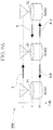
- FIG. 1 is a schematic diagram illustrating the configuration of a wireless communication system 100 in accordance with a first embodiment.
- the wireless communication system 100 in accordance with the present embodiment includes wireless terminal station apparatuses 10a and 10b arranged at both ends, and a wireless relay station apparatus 20 arranged between the wireless terminal station apparatuses 10a and 10b.
- the wireless terminal station apparatuses 10a and 10b have the same configuration, and they will be referred to as a wireless terminal station apparatus(es) 10 when indicating one or both of them.
- A denotes a signal which is transmitted from the wireless terminal station apparatus 10a (a wireless terminal station apparatus 30a in a second embodiment which will be described later) (Node 1) at a time T1
- B denotes a signal which is transmitted from the wireless terminal station apparatus 10b (a wireless terminal station apparatus 30b in the second embodiment) (Node 3) at a time T2
- A+B denotes a signal which is transmitted from the wireless relay station apparatus 20 (a wireless relay station apparatus 40 in the second embodiment) (Node 2) at a time T3.
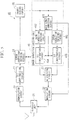
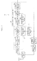
- FIG. 2 is a schematic block diagram illustrating the configuration of the wireless terminal station apparatus 10 in accordance with the present embodiment.
- the wireless terminal station apparatus 10 includes an error correction encoding circuit 11, a transmission packet storing circuit 12, a modulating circuit 13, a wireless unit 14, a demodulating circuit 15, a bit soft-decision circuit 16, a replica packet generating unit 17, an NC (network coding) decoding circuit 18, and an error correction decoding unit 19.
- the error correction decoding unit 19 includes an error correction decoding circuit 191.
- a packet to be transmitted is input to the error correction encoding circuit 11 and the transmission packet storing circuit 12.
- the error correction encoding circuit 11 performs error correction encoding on the input packet and outputs an error correction encoded packet to the modulating circuit 13.
- the transmission packet storing circuit 12 stores the input packet.
- the modulating circuit 13 modulates (maps) bit information included in the error correction encoded packet in a baseband to generate a modulation symbol, and outputs the generated modulation symbol to the wireless unit 14.
- the wireless unit 14 up-converts the modulation symbol output from the modulating circuit 13 into an RF signal, and transmits the converted RF signal through an antenna. Furthermore, the wireless unit 14 adjusts an output level through AGC (Auto Gain Control) using an RF signal received through the antenna, down-converts the received RF signal into a modulation symbol, and outputs the converted modulation symbol to the demodulating circuit 15.
- the demodulating circuit 15 outputs a signal obtained by demodulating (demapping) the modulation symbol output from the wireless unit 14 in a baseband to the bit soft-decision circuit 16, and outputs header information received together with a packet to the replica packet generating unit 17 and the error correction decoding unit 19.
- the bit soft-decision circuit 16 performs soft decision on the signal input from the demodulating circuit 15, and outputs a soft-decision signal including soft-decision values for information bits of the packet to the NC decoding circuit 18.
- the replica packet generating unit 17 reads the packet stored in the transmission packet storing circuit 12, performs error correction encoding on the read packet using a coding rate included in the header information input from the demodulating circuit 15, generates a replica packet which is an error correction encoded packet, and outputs it to the NC decoding circuit 18.
- the NC decoding circuit 18 outputs a packet which is obtained by performing NC decoding on the soft-decision signal input from the bit soft-decision circuit 16 using the replica packet input from the replica packet generating unit 17, to the error correction decoding circuit 191.
- the error correction decoding circuit 191 performs error correction decoding on the packet which is NC decoded by the NC decoding circuit 18, and outputs the decoded packet.
- FIG. 3 is a schematic block diagram illustrating the configuration of a wireless relay station apparatus 20 in accordance with the present embodiment.
- the wireless relay station apparatus 20 includes a wireless unit 21, a demodulating circuit 22, a bit soft-decision circuit 23, an error correction decoding circuit 24, a packet storing circuit 25, an error correction encoding unit 26, an NC encoding circuit 27, and a modulating circuit 28.
- the error correction encoding unit 26 includes a coding rate setting circuit 261 and error correction encoding circuits 262 and 263.
- the wireless unit 21 adjusts an output level through AGC (Auto Gain Control) using an RF signal received through an antenna, down-converts the received RF signal into a modulation symbol, and outputs the converted modulation symbol to the demodulating circuit 22.
- the demodulating circuit 22 outputs a signal obtained by demodulating (demapping) the modulation symbol output from the wireless unit 21 in a baseband, to the bit soft-decision circuit 23. Furthermore, the demodulating circuit 22 outputs header information of a packet to the error correction decoding circuit 24 and the error correction encoding unit 26.
- the bit soft-decision circuit 23 performs soft decision on the signal input from the demodulating circuit 22, and outputs a soft-decision signal including soft-decision values for information bits of the packet, to the error correction decoding circuit 24.
- the error correction decoding circuit 24 decodes the packet by performing error correction decoding on the soft-decision signal of the packet input from the bit soft-decision circuit 23, based on a coding rate of the packet to be decoded which is included in the header information input from the demodulating circuit 22, and outputs the decoded packet to the packet storing circuit 25.
- the packet storing circuit 25 stores the packet input from the error correction decoding circuit 24.
- the coding rate setting circuit 261 determines the longer one of the two calculated data lengths as a data length of an NC encoded packet, and reduces the coding rate of the packet corresponding to the shorter one of the two data lengths, so that the data length of the packet after the error correction encoding is equal to the data length of another packet after the error correction encoding.
- the coding rates R A and R B used in the coding rate setting circuit 261 are determined based on transmission path characteristics estimated when communications are performed with the wireless terminal station apparatuses 10, and required communication quality, or they are predetermined values through, for example, pre-notification of the coding rates of the packets from the wireless terminal station apparatuses 10.
- the error correction encoding circuits 262 and 263 read the packets from the packet storing circuit 25, perform error correction encoding on the read packets using the coding rates input from the coding rate setting circuit 261, and output the error correction encoded packets to the NC encoding circuit 27. Furthermore, the error correction encoding circuits 262 and 263 are provided with encoders for realizing the coding rates input from the coding rate setting circuit 261, pre-store code books which define the details of bit puncture patterns, and perform a process in accordance with indexes for the code books input from the coding rate setting circuit 261. Furthermore, the indexes for the code books are included in header information and are transmitted together with an NC encoded packet to the wireless terminal station apparatuses 10.
- the NC encoding circuit 27 performs NC encoding on the error correction encoded packets input from the error correction encoding circuits 262 and 263 using linear coding, and outputs the NC encoded packet to the modulating circuit 28.
- the NC encoding for example, uses a function having linearity such as an XOR (exclusive OR) operation.
- the modulating circuit 28 modulates the packet NC encoded by the NC encoding circuit 27 in a baseband, and outputs the converted modulation symbol to the wireless unit 21.
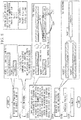
- FIG. 4 is a flowchart illustrating the operation of the wireless relay station apparatus 20 in accordance with the present embodiment.
- the packet length L A of the packet A transmitted from the wireless terminal station apparatus 10a to the wireless terminal station apparatus 10b is set to 1000 bytes, and the coding rate R A required for satisfying communication quality that is necessary for a transmission path of the second hop from the wireless relay station apparatus 20 to the wireless terminal station apparatus 10b is set to 2/3.
- the packet length L B of the packet B transmitted from the wireless terminal station apparatus 10b to the wireless terminal station apparatus 10a is set to 700 bytes, and the coding rate R B required for satisfying communication quality that is necessary for a transmission path of a hop from the wireless relay station apparatus 20 to the wireless terminal station apparatus 10a is set to 1/2.
- a packet A to be transmitted is input to the error correction encoding circuit 11 and the transmission packet storing circuit 12.
- the error correction encoding circuit 11 performs error correction encoding on the input packet A and outputs an error correction encoded packet A to the modulating circuit 13.
- the transmission packet storing circuit 12 stores the input packet A.
- the modulating circuit 13 modulates the error correction encoded packet A and converts it into a modulation symbol A, and outputs the converted modulation symbol A to the wireless unit 14.
- the wireless unit 14 up-converts the input modulation symbol A into an RF signal A, and transmits the generated RF signal A to the wireless relay station apparatus 20 through the antenna.
- the wireless unit 21 receives the RF signal A through the antenna, down-converts the received RF signal A into a modulation symbol A, and outputs the converted modulation symbol A to the demodulating circuit 22.
- the demodulating circuit 22 outputs a signal of a packet A obtained by demodulating (demapping) the input modulation symbol A to the bit soft-decision circuit 23.
- the bit soft-decision circuit 23 performs soft decision on the input signal of the packet A, and outputs a soft-decision signal of the packet A to the error correction decoding circuit 24.
- the error correction decoding circuit 24 stores the packet A, which is obtained by performing error correction decoding on the input soft-decision signal of the packet A, in the packet storing circuit 25.
- a packet B to be transmitted is input to the error correction encoding circuit 11 and the transmission packet storing circuit 12.
- the wireless terminal station apparatus 10b converts the packet B into an RF signal B and outputs it to the wireless relay station apparatus 20 in the same manner as the wireless terminal station apparatus 10a.
- the wireless unit 21 receives the RF signal B through the antenna, and, similarly to the RF signal A, a packet B obtained through demodulation and error correction decoding is stored in the packet storing circuit 25.
- the wireless relay station apparatus 20 receives and demodulates the packet A and the packet B, and stores them in the packet storing circuit 25 (step S101).
- the NC encoding circuit 27 performs NC encoding on the error correction encoded packets A and B input from the error correction encoding circuits 262 and 263, thereby generating an NC packet C (step S104).
- the modulating circuit 28 modulates the NC packet C generated by the NC encoding circuit 27 and converts it into a modulation packet C.
- the wireless unit 21 up-converts the modulation packet C converted by the modulating circuit 28 to convert it into an RF signal C, and transmits the converted RF signal C to the wireless terminal station apparatuses 10a and 10b through the antenna (steps S105 and S106).
- the wireless unit 14 down-converts the received RF signal C into a modulation packet C.
- the bit soft-decision circuit 16 performs soft decision on the signal of an NC packet C demodulated by the demodulating circuit 15 to generate a soft-decision signal of the NC packet C, and outputs it to the NC decoding circuit 18.
- the replica packet generating unit 17 reads the packet A from the transmission packet storing circuit 12, performs error correction encoding on the read packet A using the coding rate R A input from the demodulating circuit 15, and outputs an error correction encoded packet A to the NC decoding circuit 18.
- the NC decoding circuit 18 performs NC decoding through an XOR operation on the NC packet C input from the bit soft-decision circuit 16 and the error correction encoded packet A input from the replica packet generating unit 17, thereby calculating an error correction encoded packet B.
- the wireless terminal station apparatus 10b Similarly to the wireless terminal station apparatus 10a, the wireless terminal station apparatus 10b generates a replica packet from the packet B stored in the transmission packet storing circuit 12, and performs NC decoding using the generated replica packet, thereby calculating and acquiring a packet A from the RF signal C received in the wireless unit 14.
- the wireless communication system 100 transmits the packet A and the packet B.
- the error correction encoding unit 26 performs error correction encoding on the packet A and the packet B. Consequently, it is possible to apply different coding rates to the packet A and the packet B, to suppress an increase in the data length of a packet to be transmitted as illustrated in FIG 9B , and to overcome inefficiency.
- the coding rate setting circuit 261 calculates data lengths if error correction encoding is performed using the coding rates required for the packet A and the packet B, and reduces the coding rate of the packet having a shorter data length so that the data lengths of the two packets after the error correction encoding coincide with each other, and thus the coding rates to be applied to the packet A and the packet B can satisfy coding rates required for desired communication quality. Furthermore, while zero padding appends redundant data not contributing to error correction, coding rates for the packet A and the packet B are changed so that data lengths after error correction encoding coincide with each other, resulting in improved transmission quality.
- a wireless communication system 200 in accordance with a second embodiment is provided with two wireless terminal station apparatuses 30a and 30b, and a wireless relay station apparatus 40, similarly to the wireless communication system 100 in accordance with the first embodiment illustrated in FIG 1 . Furthermore, the wireless terminal station apparatuses 30a and 30b have the same configuration, and they will be referred to as wireless terminal station apparatus(es) 30 when indicating one or both of them.
- FIG. 5 is a schematic block diagram illustrating the configuration of the wireless relay station apparatus 40 in accordance with the second embodiment.
- the wireless relay station apparatus 40 is provided with a wireless unit 21, a demodulating circuit 22, a bit soft-decision circuit 23, an error correction decoding circuit 24, a packet storing circuit 25, an error correction encoding unit 46, an NC encoding circuit 27, and a modulating circuit 28.
- the error correction encoding unit 46 includes a data length comparing circuit 461, error correction encoding circuits 462 and 463, and bit concatenation circuits 464 and 465.
- the same reference numerals 21 to 25 and 27 and 28 are used to designate the same components as those of the wireless relay station apparatus 20 of the first embodiment, and a detailed description thereof will be omitted.
- the packet length adjustment information is information including an instruction for appending concatenated bit(s) having a data length of
- the data length comparing circuit 461 outputs, to the modulating circuit 28, a packet to which the concatenated bit(s) have been appended and concatenation bit information indicating the data length of the appended concatenation bit(s).
- the concatenation bit information is incorporated into header information of the packet together with the coding rates of the packet A and the packet B, and is output to the wireless terminal station apparatuses 30.
- the error correction encoding circuits 462 and 463 read packets from the packet storing circuit 25, perform error correction encoding using coding rates corresponding to communication quality required for the respective packets, and output error correction encoded packets to the bit concatenation circuits 464 and 465.
- the coding rates corresponding to the required communication quality are calculated using the state of a transmission path or the like between the station itself and the wireless terminal station apparatuses 30, which are destinations of the packet, or they are values that are predetermined by, for example, the designation from the wireless terminal station apparatuses 30, which are the destinations of the packet, before the error correction encoding circuits 462 and 463 perform error correction encoding.
- the bit concatenation circuit 464 When the packet length adjustment information is input from the data length comparing circuit 461, the bit concatenation circuit 464 generates concatenation bit(s) having the data length of
- the bit concatenation circuit 465 has the same configuration as that of the bit concatenation circuit 464, and appends concatenation bit(s) to the error correction encoded packet input from the error correction encoding circuit 463 depending on whether or not the packet length adjustment information is input from the data length comparing circuit 461, and outputs it the NC encoding circuit 27.
- a copy source of a concatenation bit is selected as follows. A description will be given of the case in which data lengths after error correction encoding is performed on two packets to be subject to network encoding are set as D 1 and D 2 (D 1 ⁇ D 2 ), and a bit length of the concatenation bit(s) is set as D c .
- the copy source bit(s) are selected in accordance with a bit number bn expressed by following Equation 1. That is, in an error correction encoded packet having a shorter data length, copy source bits are selected and copied such that the distance among the copy source bits is the largest and the copy source bits are arranged at uniform intervals.
- a may be arbitrarily set within the above range.
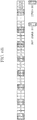
- FIGS. 6A to 6C are diagrams illustrating examples of arrangement positions (bit sequences after packet length adjustment) of concatenation bits in the present embodiment.
- FIG. 6A is an example in which copied bit sequences are gathered and are arranged at an arbitrary position of the original bit sequence.
- FIG. 6B illustrates an example in which copied bits are arranged such that the position of a copy source bit is closest to the position of a copied bit.
- FIG. 6C illustrates an example in which copied bits are arranged such that the position of a copy source bit is farthest from the position of a copied bit.
- D 1 is 3200 bits
- D 2 is 4000 bits
- D 1 ⁇ D C and D C is an integer multiple of D 1
- the entirety of an error correction encoded packet is selected as copy source bits and the selected bits are copied (D C /D 1 ) times.
- D C is not an integer multiple of D 1
- the entirety of an error correction encoded packet is selected as copy source bits, the selected bits are copied by floor (D C /D 1 ), and, for an insufficient portion (a fractional portion), copy source bits are selected and the selected bits are copied similarly to the case in which D 1 ⁇ D C .
- the floor (X) is a floor function and indicates the maximum integer which is less than or equal to X with respect to a real number X.
- an arrangement position of bits obtained by selecting and copying the copy source bits is the end of the error correction encoded packet and all concatenation bits (concatenated copied bits) are appended to the end of the packet.
- the copied bits are appended to the end of the error correction encoded packet.
- the position at which the copied bits are appended may be any position of the error correction encoded packet; for example, the copied bits may be appended to the head thereof.
- the bit concatenation circuits 464 and 465 select copy source bit(s) from a packet having a shorter data length after error correction encoding, and arrange copied bit(s) (concatenation bit(s)) obtained by copying information of the copy source bit(s) at a predetermined position of the packet.
- copied bit(s) concatenation bit(s) obtained by copying information of the copy source bit(s) at a predetermined position of the packet.
- the position where the copied bit(s) are arranged may be a position adjacent to the copy source bit(s) as illustrated in FIG. 6B .
- an input timing of the copied bit(s) is advanced in a soft-combining circuit 393 (which will be described later) of the wireless terminal station apparatuses 30.
- a waiting time until soft combining starts can be reduced and a process delay relating to error correction decoding can be reduced.
- D 1 is 3200 bits
- D 2 is 4000 bits
- D C is 800 bits
- a 1.
- the position where the copied bit(s) are arranged may be a position such that a constant bit interval is provided between a copy source bit and a copied bit. That is, copied bits may also be arranged at equal intervals on a bit-by-bit basis.
- the constant bit interval is calculated from a relation between the data length D 1 of the error correction encoded packet having a shorter data length and the data length D C of the concatenated bit(s), for example, floor (D 1 /D C ). Consequently, as compared with the arrangement illustrated in FIG.
- D 1 is 3200 bits
- D 2 is 4000 bits
- D C is 800 bits
- an interleaver dedicated to copied bit sequences may also be used to arrange a bit sequence obtained by performing interleaving on the copied bits.
- FIG. 7 is a schematic block diagram illustrating the configuration of the wireless terminal station apparatus 30 in accordance with the present embodiment.
- the wireless terminal station apparatus 30 is provided with an error correction encoding circuit 11, a transmission packet storing circuit 12, a modulating circuit 13, a wireless unit 14, a demodulating circuit 15, a bit soft-decision circuit 16, a replica packet generating unit 37, an NC decoding circuit 18, and an error correction decoding unit 39.
- the error correction decoding unit 39 includes a packet extraction circuit 391, a concatenated bit extraction circuit 392, the soft-combining circuit 393, and an error correction decoding circuit 394.
- the same reference numerals (11 to 16 and 18) are assigned to the same components as those of the wireless terminal station apparatus 10 ( FIG. 2 ) of the first embodiment, and a detailed description thereof will be omitted.
- the replica packet generating unit 37 reads a packet stored in the transmission packet storing circuit 12, and performs error correction encoding on the read packet based on a coding rate included in header information input from the demodulating circuit 15. In addition, the replica packet generating unit 37 generates concatenation bit(s) based on concatenation bit information included in the header information, generates a replica packet by appending the generated concatenation bit(s) to an error correction encoded packet, and outputs the generated replica packet to the NC decoding circuit 18.
- the packet extraction circuit 391 deletes the concatenated bit(s) from a packet that has been NC decoded by the NC decoding circuit 18 based on the concatenation bit information included in the header information input by the demodulating circuit 15, and outputs a packet obtained by deleting the concatenated bit(s) to the soft-combining circuit 393.
- the concatenated bit extraction circuit 392 extracts the concatenated bit(s) from the packet that has been NC decoded by the NC decoding circuit 18 based on the concatenation bit information included in the header information input by the demodulating circuit 15, and outputs the extracted concatenated bit(s) to the soft-combining circuit 393.
- the soft-combining circuit 393 performs soft combining on the packet input from the packet extraction circuit 391 and the concatenated bit(s) input from the concatenated bit extraction circuit 392, and outputs the result of the soft combining to the error correction decoding circuit 394.
- a concatenation bit which is expressed using a soft-decision value, and a bit serving as a copy source of the concatenation bit are added to each other.
- the error correction decoding circuit 394 performs error correction decoding on a packet input from the soft-combining circuit 393 based on the coding rate included in the header information input from the demodulating circuit 15, and outputs a decoded packet.
- FIG. 8 is a flowchart illustrating the operation of the wireless relay station apparatus 40 in accordance with the present embodiment.
- the packet length L A of the packet A transmitted from the wireless terminal station apparatus 30a to the wireless terminal station apparatus 30b is set to 1000 bytes and the coding rate R A required for satisfying communication quality necessary for a transmission path of a hop (transmission) from the wireless relay station apparatus 40 to the wireless terminal station apparatus 30b is set to 2/3.
- the packet length L B of the packet B transmitted from the wireless terminal station apparatus 30b to the wireless terminal station apparatus 30a is set to 700 bytes and the coding rate R B required for satisfying communication quality necessary for a transmission path of a hop from the wireless relay station apparatus 40 to the wireless terminal station apparatus 30a is set to 1/2.
- a packet A to be transmitted is input to the error correction encoding circuit 11 and the transmission packet storing circuit 12.
- the error correction encoding circuit 11 performs error correction encoding on the input packet A and outputs an error correction encoded packet A to the modulating circuit 13.
- the transmission packet storing circuit 12 stores the input packet A.
- the modulating circuit 13 modulates the error correction encoded packet A and converts it into a modulation symbol A.
- the wireless unit 14 up-converts the modulation symbol A converted by the modulating circuit 13 into an RF signal A, and transmits the generated RF signal A to the wireless relay station apparatus 40 through the antenna.
- the wireless unit 21 receives the RF signal A through the antenna, and down-converts the received RF signal A into a modulation symbol A.
- the demodulating circuit 22 outputs a signal obtained by demodulating the modulation symbol A converted by the wireless unit 21 to the bit soft-decision circuit 23.
- the bit soft-decision circuit 23 performs soft decision on the input signal of the packet A, and generates a soft-decision signal of the packet A.
- the error correction decoding circuit 24 stores a packet A which is obtained by performing error correction decoding on the soft-decision signal of the packet A generated by the bit soft-decision circuit 23, in the packet storing circuit 25.
- a packet B to be transmitted is input to the error correction encoding circuit 11 and the transmission packet storing circuit 12.
- the wireless terminal station apparatus 30b converts the packet B into an RF signal B and outputs the converted RF signal B to the wireless relay station apparatus 40 in the same manner as the wireless terminal station apparatus 30a.
- the wireless unit 21 receives the RF signal B through the antenna, and similarly to the RF signal A, a packet B which is obtained through demodulation and error correction decoding, is stored in the packet storing circuit 25 (step S201).
- the data length comparing circuit 461 calculates the difference between the calculated data lengths D A and D B , and outputs packet length adjustment information to the bit concatenation circuit 465.
- the packet length adjustment information includes information indicating the difference (100 bytes) between the data lengths of the packets A and B after the error correction encoding, and an instruction for appending concatenation bits having a data length corresponding to the difference to an error correction encoded packet B.
- the error correction encoding circuit 462 performs error correction encoding on the packet A which has been read from the packet storing circuit 25 using the coding rate R A required for the packet A, and outputs an error correction encoded packet A to the bit concatenation circuit 464.
- the error correction encoding circuit 463 performs error correction encoding on the packet B which has been read from the packet storing circuit 25 using the coding rate R B required for the packet B, and outputs the error correction encoded packet B to the bit concatenation circuit 465.
- the bit concatenation circuit 464 outputs the error correction encoded packet A input from the error correction encoding circuit 462 to the NC encoding circuit 27.
- the NC encoding circuit 27 performs NC encoding on the error correction encoded packets A and B' to generate an NC packet C (step S204).
- the modulating circuit 28 modulates the NC packet C generated by the NC encoding circuit 27 and converts it into a modulation packet C (step S205).
- the wireless unit 21 up-converts the modulation packet C converted by the modulating circuit 28 into an RF signal C, and transmits the converted RF signal C to the wireless terminal station apparatuses 30a and 30b through the antenna (step S206).
- the wireless unit 14 down-converts the received RF signal C into a modulation packet C.
- the demodulating circuit 15 demodulates the modulation packet C converted by the wireless unit 14 to generate a signal of an NC packet C, outputs it to the bit soft-decision circuit 16, outputs header information of the modulation packet C and a data length of the NC packet C to the replica packet generating unit 37, and also outputs the header information to the error correction decoding unit 39.
- the bit soft-decision circuit 16 performs soft decision on the input signal of the NC packet C, and outputs a soft-decision signal of the NC packet C to the NC decoding circuit 18.
- the NC decoding circuit 18 performs NC decoding on the soft-decision signal of the NC packet C input from the bit soft-decision circuit 16 using the error correction encoded packet A input from the replica packet generating unit 37 to calculate an error correction encoded packet B', and outputs the error correction encoded packet B' to the packet extraction circuit 391 and the concatenated bit extraction circuit 392.
- the packet extraction circuit 391 deletes the concatenated bits included in the error correction encoded packet B', and outputs an error correction encoded packet B to the soft combining circuit 393.
- the concatenated bit extraction circuit 392 extracts the concatenated bits included in the error correction encoded packet B', and outputs the extracted concatenated bits to the soft combining circuit 393.
- the soft combining circuit 393 combines the input concatenated bits with copy source bits included in the error correction encoded packet B in accordance with a concatenated bit selection rule, and outputs the obtained error correction encoded packet B to the error correction decoding circuit 394.
- the error correction decoding circuit 394 calculates a packet B by performing error correction decoding on the error correction encoded packet B input from the soft combining circuit 393, and outputs the calculated packet B to an upper layer or the like.
- the wireless unit 14 down-converts the received RF signal C into a modulation symbol C.
- the replica packet generating unit 37 appends (
- the NC decoding circuit 18 calculates an error correction encoded packet A by performing NC decoding on the input NC packet C using the input error correction encoded packet B', and outputs the calculated error correction encoded packet A to the packet extraction circuit 391 and the concatenated bit extraction circuit 392.
- the packet extraction circuit 391 outputs the input error correction encoded packet A to the soft combining circuit 393 in accordance with a concatenation bit length (zero) input from the demodulating circuit 15.
- the concatenated bit extraction circuit 392 outputs information indicating the absence of the appended concatenation bits to the soft combining circuit 393 in accordance with the concatenation bit length (zero) of the packet A included in the header information input from the demodulating circuit 15.
- the soft combining circuit 393 outputs the input error correction encoded packet A to the error correction decoding circuit 394 without performing any combining; that is, the soft combining circuit 393 outputs the input error correction encoded packet A to the error correction decoding circuit 394.
- the error correction decoding circuit 394 calculates a packet A by performing error correction decoding on the error correction encoded packet A input from the soft combining circuit 393, and outputs the calculated packet A to an upper layer or the like.
- the wireless communication system 200 performs the transmission of the packet A and the packet B.
- the error correction encoding unit 46 performs error correction encoding on the packet A and the packet B, before the NC encoding circuit 27 performs NC encoding on the packet A and the packet B. Consequently, it is possible to apply different coding rates to the packet A and the packet B, to suppress an increase in the data length of a packet to be transmitted as illustrated in FIG 9B , and to overcome inefficiency.
- the bit concatenation circuits 464 and 465 allow the data lengths to coincide with each other by appending concatenation bit(s), which are obtained by copying bits included in an error correction encoded packet, to the error correction encoded packet. Then, in the wireless terminal station apparatuses 30a and 30b, the error correction decoding unit 39 obtains a diversity effect by performing soft combining using the appended concatenated bits, resulting in improvement of the reliability of the error correction encoded packet to which the concatenated bit(s) have been appended.
- the wireless communication system 200 of the present embodiment allows data lengths of packets to be subject to NC encoding to coincide with each other through a simple process for appending concatenation bit(s) after error correction encoding. Consequently, it is effective even when coding rates cannot be freely selectable as with the wireless communication system 100 of the first embodiment.
- the bit concatenation circuits 464 and 465 may use selection methods other than the above-mentioned selection method of the copy source bits. For example, when a modulation scheme used in wireless transmission from the wireless relay station apparatus 20 (40) to the wireless terminal station apparatuses 10 (30) is multilevel quadrature modulation of 16 QAM (Quadrature Amplitude Modulation) or more using Gray arrangement, since the error tolerance of the least significant bit in each modulation symbol is reduced, the least significant bit of each modulation symbol is preferentially selected as a copy source bit.
- a modulation scheme used in wireless transmission from the wireless relay station apparatus 20 (40) to the wireless terminal station apparatuses 10 (30) is multilevel quadrature modulation of 16 QAM (Quadrature Amplitude Modulation) or more using Gray arrangement
- the least significant bit of each modulation symbol is preferentially selected as a copy source bit.
- copy source bits are selected every 2 bits to generate concatenation bits.
- D C D 1 /2
- the least significant bit as well as the most significant bit may also be selected as copy source bits, or the least significant bit may also be copied a plurality of times.
- copy source bits are selected every 3 bits to generate concatenation bits.
- D C >D 1 /3
- the least significant bit as well as the most significant bit and an intermediate bit may also be selected as copy source bits, or the least significant bit may also be copied a plurality of times.
- the network configuration is the Alice-and-Bob topology.
- the network configuration is not limited thereto, and a network configuration such as X topology or chain topology may also be used.
- decoding of a network encoded NC packet is performed using a received native packet (a packet not NC encoded) instead of a transmitted packet.
- the coding rate setting circuit 261 changes a coding rate in accordance with a packet length after error correction encoding.
- a coding rate close to a desired coding rate is selected from among the selectable coding rates, so that data lengths, between which a difference is generated after error correction encoding, are allowed to coincide with each other using concatenation bit(s). Consequently, it is possible to reduce the size of circuits required for error correction encoding and error correction decoding.
- a plurality of packets may be concatenated to the packet A and the packet B, respectively, so that final data lengths after the concatenation coincide with each other. Since packets having various data lengths flow through a network, as a result of the concatenation of the plurality of packets, data lengths of the concatenated packets statistically approach the same data length. Consequently, it is possible to transmit more packets at a time and to obtain an advantageous effect that data lengths of packets to be subject to network encoding are approximately equal to each other, resulting in improvement of system throughput.
- data lengths after error correction encoding has been performed on the concatenated packets may be allowed to coincide with each other through a combination of the technique for concatenating a plurality of packets and adjustment of data lengths in accordance with the first embodiment and the second embodiment.
- the wireless relay station apparatus may control the packet storing circuit such that network encoding is performed on the packets with the same QoS class. Consequently, it is possible to allow data lengths of the packets subject to the network encoding to coincide with each other, resulting in improvement of system throughput.
- QoS Quality of Service
- final data lengths may be allowed to coincide with each other through a combination of the control technique of the packet storing circuit based on the QoS and adjustment of data lengths in accordance with the first embodiment and the second embodiment.
- the present invention is applied to, for example, a wireless communication system to which network coding is applied.
- it is possible to set transmission quality for each destination of packets and improve the throughput of the wireless communication system.
Landscapes
- Engineering & Computer Science (AREA)
- Computer Networks & Wireless Communication (AREA)
- Signal Processing (AREA)
- Quality & Reliability (AREA)
- Mobile Radio Communication Systems (AREA)
- Detection And Prevention Of Errors In Transmission (AREA)
- Radio Relay Systems (AREA)
Claims (13)
- Drahtloses Relaisstationsgerät (20), das ein erstes Paket und ein zweites Paket zu einer Mehrzahl von drahtlosen Terminalstationsgeräten (10a, 10b) überträgt, wobei das erste Paket von dem zweiten Paket verschieden ist, wobei das drahtlose Relaisstationsgerät umfasst:eine Fehlerkorrekturkodierungseinheit (262, 263), die Kodierungsraten zur Verwendung für das erste Paket und das zweite Paket in Übereinstimmung mit einer Kommunikationsqualität auswählt, die für das erste Paket und das zweite Paket erforderlich ist, und fehlerkorrekturkodierte Pakete mit der gleichen Datenlänge aus dem ersten Paket und dem zweiten Paket unter Verwendung der ausgewählten Kodierungsraten generiert;eine Netzwerkkodierungsschaltung (27), die eine Netzwerkkodierung auf fehlerkorrekturkodierten ersten und zweiten Paketen durchführt, um ein netzwerkkodiertes Paket zu generieren; undeine Übertragungsschaltung (28, 21), die das netzwerkkodierte Paket zu der Mehrzahl von drahtlosen Terminalstationsgeräten überträgt,wobei die Fehlerkorrekturkodierungseinheit Paketlängen D1 und D2 berechnet, wenn eine Fehlerkorrekturkodierung durchgeführt wird unter Verwendung der Kodierungsraten R1 und R2, die für das erste Paket und das zweite Paket erforderlich sind, die für das erste Paket erforderliche Kodierungsrate von R1 zu R1' = L1 / (L2 / R2) ändert, wenn die berechnete Paketlänge D1 kürzer ist als die berechnete Paketlänge D2, wobei L1 und L2 Paketlängen des ersten Pakets beziehungsweise des zweiten Pakets sind, die für das zweite Paket erforderliche Kodierungsrate von R2 zu R2' = L2 / (L1 / R1) ändert, wenn die berechnete Paketlänge D1 länger ist als die berechnete Paketlänge D2, und eine Fehlerkorrekturkodierung derart durchführt, dass das fehlerkorrekturkodierte erste Paket und das fehlerkorrekturkodierte zweite Paket die gleiche Paketlänge haben.
- Drahtloses Relaisstationsgerät nach Anspruch 1, wobei dann, wenn es eine Differenz zwischen Datenlängen gibt, wenn die Fehlerkorrekturkodierung auf dem ersten Paket und dem zweiten Paket durchgeführt wird, die Fehlerkorrekturkodierungseinheit ein Verknüpfungsbit generiert durch Kopieren eines Bits, das in einem fehlerkorrekturkodierten Paket mit einer kürzeren Datenlänge enthalten ist, das Verknüpfungsbit an das fehlerkorrekturkodierte Paket mit der kürzeren Datenlänge anhängt, und ermöglicht, dass die Datenlängen des fehlerkorrekturkodierten ersten und zweiten Pakets miteinander zusammenfallen.
- Drahtloses Relaisstationsgerät nach Anspruch 2, wobei dann, wenn eine Multilevelquadraturmodulation zur drahtlosen Übertragung von dem drahtlosen Relaisstationsgerät zu der Mehrzahl von drahtlosen Terminalstationsgeräten verwendet wird, die Fehlerkorrekturkodierungseinheit vorzugsweise wenigstens ein signifikantes Bit aus Bits auswählt, die ein Modulationssymbol bilden, generiert durch die Multilevelquadraturmodulation, und zwar als ein Kopiequellenbit des Verknüpfungsbits.
- Drahtloses Relaisstationsgerät nach Anspruch 2 oder 3, wobei die Fehlerkorrekturkodierungseinheit kollektiv Verknüpfungsbits an einer vorbestimmten Position des fehlerkorrekturkodierten Pakets mit der kürzeren Datenlänge anordnet.
- Drahtloses Relaisstationsgerät nach Anspruch 2 oder 3, wobei die Fehlerkorrekturkodierungseinheit ein Bit, das das Verknüpfungsbit bildet, welches durch Kopieren eines Kopierquellenbits erhalten ist, an einer Position anordnet, die benachbart dem Kopierquellenbit des Bits ist, das das Verknüpfungsbit bildet.
- Drahtloses Relaisstationsgerät nach Anspruch 2 oder 3, wobei die Fehlerkorrekturkodierungseinheit ein Bit, das das Verknüpfungsbit bildet, an einer Position anordnet, die von einem Kopierquellenbit des Bits, das das Verknüpfungsbit bildet, um ein konstantes Bitintervall beabstandet ist.
- Drahtloses Kommunikationssystem (100), umfassend:ein drahtloses Relaisstationsgerät (20), das ein erstes Paket und ein zweites Paket zu einer Mehrzahl von drahtlosen Terminalstationsgeräten (10a, 10b) überträgt, wobei das erste Paket von dem zweiten Paket verschieden ist,wobei das drahtlose Relaisstationsgerät umfasst:eine Fehlerkorrekturkodierungseinheit (262, 263), die Kodierungsraten zur Verwendung für das erste Paket und das zweite Paket in Übereinstimmung mit einer Kommunikationsqualität auswählt, die für das erste Paket und das zweite Paket erforderlich ist, und fehlerkorrekturkodierte Pakete mit der gleichen Datenlänge aus dem ersten Paket und dem zweiten Paket unter Verwendung der ausgewählten Kodierungsraten generiert;eine Netzwerkkodierungsschaltung (27), die eine Netzwerkkodierung auf fehlerkorrekturkodierten ersten und zweiten Paketen durchführt, um ein netzwerkkodiertes Paket zu generieren; undeine Übertragungsschaltung (28, 21), die das netzwerkkodierte Paket zu der Mehrzahl von drahtlosen Terminalstationsgeräten überträgt, undwobei aus der Mehrzahl von drahtlosen Terminalstationsgeräten, jedes von einem drahtlosen Terminalstationsgerät, das ein drittes Paket gleich dem ersten Paket in einer Speicherschaltung speichert, und einem drahtlosen Terminalstationsgerät, das ein drittes Paket gleich dem zweiten Paket in einer Speicherschaltung speichert, Folgendes umfasst:eine Fehlerkorrekturkodierungseinheit (11), die eine Fehlerkorrekturkodierung auf dem dritten Paket durchführt;eine Netzwerkdekodierungsschaltung (18), die eine Netzwerkdekodierung auf dem netzwerkkodierten Paket durchführt, das empfangen worden ist, unter Verwendung eines fehlerkorrekturkodierten dritten Pakets, um ein dekodiertes Paket zu generieren; undeine Fehlerkorrekturdekodierungseinheit (19), die eine Fehlerkorrekturdekodierung auf dem dekodierten Paket durchführt,wobei die Fehlerkorrekturkodierungseinheit Paketlängen D1 und D2 berechnet, wenn eine Fehlerkorrekturkodierung durchgeführt wird unter Verwendung der Kodierungsraten R1 und R2, die für das erste Paket und das zweite Paket erforderlich sind, die für das erste Paket erforderliche Kodierungsrate von R1 zu R1' = L1 / (L2 / R2) ändert, wenn die berechnete Paketlänge D1 kürzer ist als die berechnete Paketlänge D2, wobei L1 und L2 Paketlängen des ersten Pakets beziehungsweise des zweiten Pakets sind, die für das zweite Paket erforderliche Kodierungsrate von R2 zu R2' = L2 / (L1 / R1) ändert, wenn die berechnete Paketlänge D1 länger ist als die berechnete Paketlänge D2, und eine Fehlerkorrekturkodierung derart durchführt, dass das fehlerkorrekturkodierte erste Paket und das fehlerkorrekturkodierte zweite Paket die gleiche Paketlänge haben.
- Drahtloses Kommunikationssystem nach Anspruch 7, wobei dann, wenn es eine Differenz zwischen Datenlängen gibt, wenn die Fehlerkorrekturkodierung auf dem ersten Paket und dem zweiten Paket durchgeführt wird, die Fehlerkorrekturkodierungseinheit ein Verknüpfungsbit generiert durch Kopieren eines Bits, das in einem fehlerkorrekturkodierten Paket mit einer kürzeren Datenlänge enthalten ist, das Verknüpfungsbit an das fehlerkorrekturkodierte Paket mit der kürzeren Datenlänge anhängt, und ermöglicht, dass die Datenlängen des fehlerkorrekturkodierten ersten und zweiten Pakets miteinander zusammenfallen, und
die Fehlerkorrekturdekodierungseinheit das fehlerkorrekturkodierte Paket mit der kürzeren Datenlänge und das Verknüpfungsbit aus dem dekodierten Paket extrahiert und eine Fehlerkorrekturdekodierung durchführt durch Durchführen einer Soft-Kombination auf dem fehlerkorrekturkodierten Paket mit der kürzeren Datenlänge und dem Verknüpfungsbit. - Drahtloses Kommunikationssystem nach Anspruch 8, wobei dann, wenn eine Multilevelquadraturmodulation zur drahtlosen Übertragung von dem drahtlosen Relaisstationsgerät zu der Mehrzahl von drahtlosen Terminalstationsgeräten verwendet wird, die Fehlerkorrekturkodierungseinheit vorzugsweise wenigstens ein signifikantes Bit aus Bits auswählt, die ein Modulationssymbol bilden, generiert durch die Multilevelquadraturmodulation, und zwar als ein Kopiequellenbit des Verknüpfungsbits.
- Drahtloses Kommunikationssystem nach Anspruch 8 oder 9, wobei die Fehlerkorrekturkodierungseinheit kollektiv Verknüpfungsbits an einer vorbestimmten Position des fehlerkorrekturkodierten Pakets mit der kürzeren Datenlänge anordnet.
- Drahtloses Kommunikationssystem nach Anspruch 8 oder 9, wobei die Fehlerkorrekturkodierungseinheit ein Bit, das das Verknüpfungsbit bildet, welches durch Kopieren eines Kopierquellenbits erhalten ist, an einer Position anordnet, die benachbart dem Kopierquellenbit des Bits ist, das das Verknüpfungsbit bildet.
- Drahtloses Kommunikationssystem nach Anspruch 8 oder 9, wobei die Fehlerkorrekturkodierungseinheit ein Bit, das das Verknüpfungsbit bildet, an einer Position anordnet, die von einem Kopierquellenbit des Bits, das das Verknüpfungsbit bildet, um ein konstantes Bitintervall beabstandet ist.
- Drahtloses Kommunikationsverfahren in einem drahtlosen Kommunikationssystem (100), das mit einem drahtlosen Relaisstationsgerät (20) versehen ist, das ein erstes Paket und ein zweite Paket zu einer Mehrzahl von drahtlosen Terminalstationsgeräten (10a, 10b) überträgt, wobei das erste Paket von dem zweiten Paket verschieden ist, wobei das drahtlose Kommunikationsverfahren umfasst:einen Schritt des Auswählens, durch eine Fehlerkorrekturkodierungseinheit (262, 263) des drahtlosen Relaisstationsgeräts, von Kodierungsraten zur Verwendung für das erste Paket und das zweite Paket in Übereinstimmung mit einer Kommunikationsqualität, die für das erste Paket und das zweite Paket erforderlich ist, und des Generierens von fehlerkorrekturkodierten Paketen mit der gleichen Datenlänge aus dem ersten Paket und dem zweiten Paket unter Verwendung der ausgewählten Kodierungsraten, wobei die Fehlerkorrekturkodierungseinheit des drahtlosen Relaisstationsgeräts Paketlängen D1 und D2 berechnet, wenn eine Fehlerkorrekturkodierung durchgeführt wird, unter Verwendung der für das erste Paket und das zweite Paket erforderlichen Kodierungsraten R1 und R2, die für das erste Paket erforderliche Kodierungsrate von R1 zu R1' = L1 / (L2 / R2) ändert, wenn die berechnete Paketlänge D1 kürzer ist als die berechnete Paketlänge D2, wobei L1 und L2 Paketlängen des ersten Pakets beziehungsweise des zweiten Pakets sind, die für das zweite Paket erforderliche Kodierungsrate von R2 zu R2' = L2 / (L1 / R1) ändert, wenn die berechnete Paketlänge D1 länger ist als die berechnete Paketlänge D2, und eine Fehlerkorrekturkodierung derart durchführt, dass das fehlerkorrekturkodierte erste Paket und das fehlerkorrekturkodierte zweite Paket die gleiche Paketlänge haben;einen Schritt des Durchführens, durch eine Netzwerkkodierungsschaltung (27) des drahtlosen Relaisstationsgeräts, einer Netzwerkkodierung auf fehlerkorrekturkodierten ersten und zweiten Paketen zum Generieren eines netzwerkkodierten Pakets;einen Schritt des Übertragens, durch eine Übertragungsschaltung (28, 21) des drahtlosen Relaisstationsgeräts, des netzwerkkodierten Pakets zu der Mehrzahl von drahtlosen Terminalstationsgeräten;einen Schritt des Durchführens, durch eine Fehlerkorrekturkodierungseinheit (11) eines drahtlosen Terminalstationsgeräts, das ein drittes Paket gleich dem ersten Paket in einer Speicherschaltung speichert, aus der Mehrzahl von drahtlosen Terminalstationsgeräten, einer Fehlerkorrekturkodierung auf dem gespeicherten dritten Paket;einen Schritt des Durchführens, durch eine Fehlerkorrekturkodierungseinheit (11) eines drahtlosen Terminalstationsgeräts, das ein drittes Paket gleich dem zweiten Paket in einer Speicherschaltung speichert, aus der Mehrzahl von drahtlosen Terminalstationsgeräten, einer Fehlerkorrekturkodierung auf dem gespeicherten dritten Paket;einen Schritt des Durchführens, durch Netzwerkdekodierungsschaltungen (18) der Mehrzahl von drahtlosen Terminalstationsgeräten, einer Netzwerkdekodierung auf dem netzwerkkodierten Paket, das empfangen worden ist, unter Verwendung des fehlerkorrekturkodierten dritten Pakets zum Generieren eines dekodierten Pakets; undeinen Schritt des Durchführens, durch Fehlerkorrekturdekodierungseinheiten (19) der Mehrzahl von drahtlosen Terminalstationsgeräten, einer Fehlerkorrekturdekodierung auf dem dekodierten Paket.
Applications Claiming Priority (2)
| Application Number | Priority Date | Filing Date | Title |
|---|---|---|---|
| JP2009233740 | 2009-10-07 | ||
| PCT/JP2010/066899 WO2011043230A1 (ja) | 2009-10-07 | 2010-09-29 | 無線通信システム、無線中継局装置、無線端末局装置、及び無線通信方法 |
Publications (3)
| Publication Number | Publication Date |
|---|---|
| EP2487808A1 EP2487808A1 (de) | 2012-08-15 |
| EP2487808A4 EP2487808A4 (de) | 2017-08-09 |
| EP2487808B1 true EP2487808B1 (de) | 2018-11-14 |
Family
ID=43856688
Family Applications (1)
| Application Number | Title | Priority Date | Filing Date |
|---|---|---|---|
| EP10821901.5A Active EP2487808B1 (de) | 2009-10-07 | 2010-09-29 | Drahtloses kommunikationssystem, funkrelaisstationsvorrichtung, funkendgerätestationsvorrichtung und drahtloses kommunikationsverfahren |
Country Status (6)
| Country | Link |
|---|---|
| US (1) | US8914714B2 (de) |
| EP (1) | EP2487808B1 (de) |
| JP (1) | JPWO2011043230A1 (de) |
| KR (2) | KR101404724B1 (de) |
| CN (1) | CN102577167B (de) |
| WO (1) | WO2011043230A1 (de) |
Families Citing this family (12)
| Publication number | Priority date | Publication date | Assignee | Title |
|---|---|---|---|---|
| US8503346B2 (en) * | 2008-09-25 | 2013-08-06 | Samsung Electronics Co., Ltd. | Wireless network using network coding scheme based on overhearing channel |
| CN102237967B (zh) * | 2011-07-29 | 2018-08-14 | 中兴通讯股份有限公司 | 一种网络编码的数据块处理方法及其装置 |
| JP5822719B2 (ja) * | 2011-12-28 | 2015-11-24 | 三菱電機株式会社 | 衛星中継装置および衛星通信システム |
| WO2014077533A1 (en) | 2012-11-14 | 2014-05-22 | Samsung Electronics Co., Ltd. | Base station and a plurality of member nodes for transmitting and receiving network coding based multicast traffic |
| JP6218305B2 (ja) * | 2013-03-26 | 2017-10-25 | 日本電信電話株式会社 | 無線通信方法及び無線通信装置 |
| KR102095493B1 (ko) * | 2014-01-16 | 2020-04-16 | 삼성전자주식회사 | 무선 멀티홉 통신을 위한 신호 전달 방법 및 장치 |
| CN105471545B (zh) | 2014-09-10 | 2020-07-21 | 中兴通讯股份有限公司 | 一种数据包处理方法及装置 |
| CN106332287B (zh) * | 2015-07-01 | 2022-03-18 | 西安中兴新软件有限责任公司 | 一种数据传输方法及通信节点 |
| WO2019236476A1 (en) | 2018-06-04 | 2019-12-12 | SparkMeter, Inc. | Wireless mesh data network with increased transmission capacity |
| US12438957B1 (en) * | 2021-09-21 | 2025-10-07 | Graphiant, Inc. | Method and system for IP header compression |
| JPWO2023238205A1 (de) * | 2022-06-06 | 2023-12-14 | ||
| CN115835311B (zh) * | 2022-11-14 | 2025-12-23 | 中国联合网络通信集团有限公司 | 码率配置方法、装置、及存储介质 |
Family Cites Families (16)
| Publication number | Priority date | Publication date | Assignee | Title |
|---|---|---|---|---|
| US7570645B2 (en) * | 2000-01-18 | 2009-08-04 | Viasat, Inc. | Frame format and frame assembling/disassembling method for the frame format |
| SE0403218D0 (sv) * | 2004-12-30 | 2004-12-30 | Ericsson Telefon Ab L M | Method and apparatus relating to communication- |
| US7177804B2 (en) * | 2005-05-31 | 2007-02-13 | Microsoft Corporation | Sub-band voice codec with multi-stage codebooks and redundant coding |
| US7782896B2 (en) | 2005-08-19 | 2010-08-24 | Panasonic Corporation | Wireless communication apparatus and wireless communication method |
| CN101248604A (zh) * | 2005-08-19 | 2008-08-20 | 松下电器产业株式会社 | 无线通信装置以及无线通信方法 |
| KR20070074256A (ko) * | 2006-01-09 | 2007-07-12 | 삼성전자주식회사 | 셀룰러 망에서 릴레이를 통한 데이터 중계방법 및 이를지원하는 셀룰러 이동통신시스템 |
| JPWO2007102363A1 (ja) * | 2006-03-01 | 2009-07-23 | パナソニック株式会社 | 無線送信装置および無線送信方法 |
| JP2008028656A (ja) * | 2006-07-20 | 2008-02-07 | Shinshu Univ | 適応制御型ダイバーシチ通信システム |
| CN101843008B (zh) * | 2007-11-02 | 2014-06-04 | 富士通株式会社 | 网络编码方法和网络编码装置 |
| WO2009066451A1 (ja) | 2007-11-21 | 2009-05-28 | Panasonic Corporation | 無線通信装置、無線通信方法および無線通信システム |
| JPWO2009069262A1 (ja) * | 2007-11-29 | 2011-04-07 | パナソニック株式会社 | 無線送信装置および無線送信方法 |
| CN101453800B (zh) * | 2007-11-30 | 2012-08-08 | 株式会社Ntt都科摩 | 多跳接力系统中的双向数据传输处理方法及通信中间装置 |
| US8255753B2 (en) * | 2007-12-04 | 2012-08-28 | Intel Corporation | Encoding/decoding technique for rebroadcasting lost packets |
| JP5035045B2 (ja) * | 2008-03-14 | 2012-09-26 | 富士通株式会社 | データ中継装置、通信装置およびデータ中継方法 |
| JP2009233740A (ja) | 2008-03-28 | 2009-10-15 | Nippon Carbide Ind Co Inc | 可締め冶具 |
| US8306095B2 (en) * | 2008-04-29 | 2012-11-06 | Samsung Electronics Co., Ltd. | Methods and apparatus for network coding in a communication system |
-
2010
- 2010-09-29 EP EP10821901.5A patent/EP2487808B1/de active Active
- 2010-09-29 JP JP2011535356A patent/JPWO2011043230A1/ja active Pending
- 2010-09-29 CN CN201080043992.6A patent/CN102577167B/zh active Active
- 2010-09-29 KR KR1020127008400A patent/KR101404724B1/ko active Active
- 2010-09-29 WO PCT/JP2010/066899 patent/WO2011043230A1/ja not_active Ceased
- 2010-09-29 US US13/498,968 patent/US8914714B2/en active Active
- 2010-09-29 KR KR1020147004309A patent/KR20140032013A/ko not_active Ceased
Non-Patent Citations (1)
| Title |
|---|
| None * |
Also Published As
| Publication number | Publication date |
|---|---|
| KR20120063502A (ko) | 2012-06-15 |
| KR101404724B1 (ko) | 2014-06-09 |
| US8914714B2 (en) | 2014-12-16 |
| WO2011043230A1 (ja) | 2011-04-14 |
| EP2487808A1 (de) | 2012-08-15 |
| JPWO2011043230A1 (ja) | 2013-03-04 |
| US20120239997A1 (en) | 2012-09-20 |
| EP2487808A4 (de) | 2017-08-09 |
| CN102577167A (zh) | 2012-07-11 |
| CN102577167B (zh) | 2014-12-10 |
| KR20140032013A (ko) | 2014-03-13 |
Similar Documents
| Publication | Publication Date | Title |
|---|---|---|
| US8914714B2 (en) | Wireless communication system, wireless relay station apparatus, wireless terminal station apparatus, and wireless communication method | |
| JP4915450B2 (ja) | ネットワーク符号化方法およびネットワーク符号化装置 | |
| KR101597733B1 (ko) | 무선 통신 시스템을 위한 레이트 매칭 | |
| CN105515733B (zh) | 一种反馈方法及装置 | |
| CN101821980B (zh) | 一种发送数据的方法 | |
| KR101281252B1 (ko) | 멀티 홉 무선 통신 시스템들 내에서 협력 중계를 위한 방법 | |
| US9001776B2 (en) | Method and apparatus for transmitting/receiving control information in a wireless communication system | |
| US20070184826A1 (en) | Method for relaying in a cellular network and cellular mobile communication system supporting the same | |
| CN101534146B (zh) | 数据中继装置、通信装置及数据中继方法 | |
| EP4228168B1 (de) | Ratenanpassung zur bewahrung von grenzen von codeblockressourcenelementen | |
| CN101128997A (zh) | 用于无线通信系统中的双向中继的方法及装置 | |
| US6604216B1 (en) | Telecommunications system and method for supporting an incremental redundancy error handling scheme using available gross rate channels | |
| JPWO2009066451A1 (ja) | 無線通信装置、無線通信方法および無線通信システム | |
| KR20090061562A (ko) | 연판정을 이용한 통신방법 및 장치 | |
| US8902928B2 (en) | System and method for efficient transmission of multimedia and data | |
| US20080301534A1 (en) | Error control method and cooperative transfer system | |
| JP5415227B2 (ja) | ブロックフェージングチャネルの分散ターボ符号器 | |
| AU2008362215B9 (en) | Telecommunication method and apparatus | |
| US20120201192A1 (en) | Method and apparatus for relaying uplink signals | |
| CN105027450B (zh) | 支持连续干扰消除(sic)的前向纠错(fec) | |
| JP4943389B2 (ja) | 無線通信システム、受信端末、無線通信方法及び受信方法 | |
| KR20090042699A (ko) | 통신 시스템에서의 데이터 송수신 방법 | |
| JP4403097B2 (ja) | 無線基地局およびデータ伝送方法 | |
| JP2001211144A (ja) | 非メモリ誤り訂正チャネルコーディングの反復送受信装置及びその方法 | |
| JP6071501B2 (ja) | 中継端末 |
Legal Events
| Date | Code | Title | Description |
|---|---|---|---|
| PUAI | Public reference made under article 153(3) epc to a published international application that has entered the european phase |
Free format text: ORIGINAL CODE: 0009012 |
|
| 17P | Request for examination filed |
Effective date: 20120330 |
|
| AK | Designated contracting states |
Kind code of ref document: A1 Designated state(s): AL AT BE BG CH CY CZ DE DK EE ES FI FR GB GR HR HU IE IS IT LI LT LU LV MC MK MT NL NO PL PT RO SE SI SK SM TR |
|
| DAX | Request for extension of the european patent (deleted) | ||
| RA4 | Supplementary search report drawn up and despatched (corrected) |
Effective date: 20170710 |
|
| RIC1 | Information provided on ipc code assigned before grant |
Ipc: H04B 7/15 20060101AFI20170704BHEP Ipc: H04W 16/26 20090101ALI20170704BHEP |
|
| GRAP | Despatch of communication of intention to grant a patent |
Free format text: ORIGINAL CODE: EPIDOSNIGR1 |
|
| STAA | Information on the status of an ep patent application or granted ep patent |
Free format text: STATUS: GRANT OF PATENT IS INTENDED |
|
| INTG | Intention to grant announced |
Effective date: 20180531 |
|
| GRAS | Grant fee paid |
Free format text: ORIGINAL CODE: EPIDOSNIGR3 |
|
| GRAA | (expected) grant |
Free format text: ORIGINAL CODE: 0009210 |
|
| STAA | Information on the status of an ep patent application or granted ep patent |
Free format text: STATUS: THE PATENT HAS BEEN GRANTED |
|
| AK | Designated contracting states |
Kind code of ref document: B1 Designated state(s): AL AT BE BG CH CY CZ DE DK EE ES FI FR GB GR HR HU IE IS IT LI LT LU LV MC MK MT NL NO PL PT RO SE SI SK SM TR |
|
| REG | Reference to a national code |
Ref country code: GB Ref legal event code: FG4D |
|
| REG | Reference to a national code |
Ref country code: CH Ref legal event code: EP Ref country code: AT Ref legal event code: REF Ref document number: 1066089 Country of ref document: AT Kind code of ref document: T Effective date: 20181115 |
|
| REG | Reference to a national code |
Ref country code: DE Ref legal event code: R096 Ref document number: 602010055156 Country of ref document: DE |
|
| REG | Reference to a national code |
Ref country code: IE Ref legal event code: FG4D |
|
| REG | Reference to a national code |
Ref country code: NL Ref legal event code: MP Effective date: 20181114 |
|
| REG | Reference to a national code |
Ref country code: LT Ref legal event code: MG4D |
|
| REG | Reference to a national code |
Ref country code: AT Ref legal event code: MK05 Ref document number: 1066089 Country of ref document: AT Kind code of ref document: T Effective date: 20181114 |
|
| PG25 | Lapsed in a contracting state [announced via postgrant information from national office to epo] |
Ref country code: ES Free format text: LAPSE BECAUSE OF FAILURE TO SUBMIT A TRANSLATION OF THE DESCRIPTION OR TO PAY THE FEE WITHIN THE PRESCRIBED TIME-LIMIT Effective date: 20181114 Ref country code: LV Free format text: LAPSE BECAUSE OF FAILURE TO SUBMIT A TRANSLATION OF THE DESCRIPTION OR TO PAY THE FEE WITHIN THE PRESCRIBED TIME-LIMIT Effective date: 20181114 Ref country code: AT Free format text: LAPSE BECAUSE OF FAILURE TO SUBMIT A TRANSLATION OF THE DESCRIPTION OR TO PAY THE FEE WITHIN THE PRESCRIBED TIME-LIMIT Effective date: 20181114 Ref country code: FI Free format text: LAPSE BECAUSE OF FAILURE TO SUBMIT A TRANSLATION OF THE DESCRIPTION OR TO PAY THE FEE WITHIN THE PRESCRIBED TIME-LIMIT Effective date: 20181114 Ref country code: IS Free format text: LAPSE BECAUSE OF FAILURE TO SUBMIT A TRANSLATION OF THE DESCRIPTION OR TO PAY THE FEE WITHIN THE PRESCRIBED TIME-LIMIT Effective date: 20190314 Ref country code: NO Free format text: LAPSE BECAUSE OF FAILURE TO SUBMIT A TRANSLATION OF THE DESCRIPTION OR TO PAY THE FEE WITHIN THE PRESCRIBED TIME-LIMIT Effective date: 20190214 Ref country code: LT Free format text: LAPSE BECAUSE OF FAILURE TO SUBMIT A TRANSLATION OF THE DESCRIPTION OR TO PAY THE FEE WITHIN THE PRESCRIBED TIME-LIMIT Effective date: 20181114 Ref country code: HR Free format text: LAPSE BECAUSE OF FAILURE TO SUBMIT A TRANSLATION OF THE DESCRIPTION OR TO PAY THE FEE WITHIN THE PRESCRIBED TIME-LIMIT Effective date: 20181114 Ref country code: BG Free format text: LAPSE BECAUSE OF FAILURE TO SUBMIT A TRANSLATION OF THE DESCRIPTION OR TO PAY THE FEE WITHIN THE PRESCRIBED TIME-LIMIT Effective date: 20190214 |
|
| PG25 | Lapsed in a contracting state [announced via postgrant information from national office to epo] |
Ref country code: GR Free format text: LAPSE BECAUSE OF FAILURE TO SUBMIT A TRANSLATION OF THE DESCRIPTION OR TO PAY THE FEE WITHIN THE PRESCRIBED TIME-LIMIT Effective date: 20190215 Ref country code: NL Free format text: LAPSE BECAUSE OF FAILURE TO SUBMIT A TRANSLATION OF THE DESCRIPTION OR TO PAY THE FEE WITHIN THE PRESCRIBED TIME-LIMIT Effective date: 20181114 Ref country code: SE Free format text: LAPSE BECAUSE OF FAILURE TO SUBMIT A TRANSLATION OF THE DESCRIPTION OR TO PAY THE FEE WITHIN THE PRESCRIBED TIME-LIMIT Effective date: 20181114 Ref country code: AL Free format text: LAPSE BECAUSE OF FAILURE TO SUBMIT A TRANSLATION OF THE DESCRIPTION OR TO PAY THE FEE WITHIN THE PRESCRIBED TIME-LIMIT Effective date: 20181114 Ref country code: PT Free format text: LAPSE BECAUSE OF FAILURE TO SUBMIT A TRANSLATION OF THE DESCRIPTION OR TO PAY THE FEE WITHIN THE PRESCRIBED TIME-LIMIT Effective date: 20190314 |
|
| PG25 | Lapsed in a contracting state [announced via postgrant information from national office to epo] |
Ref country code: PL Free format text: LAPSE BECAUSE OF FAILURE TO SUBMIT A TRANSLATION OF THE DESCRIPTION OR TO PAY THE FEE WITHIN THE PRESCRIBED TIME-LIMIT Effective date: 20181114 Ref country code: IT Free format text: LAPSE BECAUSE OF FAILURE TO SUBMIT A TRANSLATION OF THE DESCRIPTION OR TO PAY THE FEE WITHIN THE PRESCRIBED TIME-LIMIT Effective date: 20181114 Ref country code: CZ Free format text: LAPSE BECAUSE OF FAILURE TO SUBMIT A TRANSLATION OF THE DESCRIPTION OR TO PAY THE FEE WITHIN THE PRESCRIBED TIME-LIMIT Effective date: 20181114 Ref country code: DK Free format text: LAPSE BECAUSE OF FAILURE TO SUBMIT A TRANSLATION OF THE DESCRIPTION OR TO PAY THE FEE WITHIN THE PRESCRIBED TIME-LIMIT Effective date: 20181114 |
|
| REG | Reference to a national code |
Ref country code: DE Ref legal event code: R097 Ref document number: 602010055156 Country of ref document: DE |
|
| PG25 | Lapsed in a contracting state [announced via postgrant information from national office to epo] |
Ref country code: SK Free format text: LAPSE BECAUSE OF FAILURE TO SUBMIT A TRANSLATION OF THE DESCRIPTION OR TO PAY THE FEE WITHIN THE PRESCRIBED TIME-LIMIT Effective date: 20181114 Ref country code: RO Free format text: LAPSE BECAUSE OF FAILURE TO SUBMIT A TRANSLATION OF THE DESCRIPTION OR TO PAY THE FEE WITHIN THE PRESCRIBED TIME-LIMIT Effective date: 20181114 Ref country code: EE Free format text: LAPSE BECAUSE OF FAILURE TO SUBMIT A TRANSLATION OF THE DESCRIPTION OR TO PAY THE FEE WITHIN THE PRESCRIBED TIME-LIMIT Effective date: 20181114 Ref country code: SM Free format text: LAPSE BECAUSE OF FAILURE TO SUBMIT A TRANSLATION OF THE DESCRIPTION OR TO PAY THE FEE WITHIN THE PRESCRIBED TIME-LIMIT Effective date: 20181114 |
|
| PLBE | No opposition filed within time limit |
Free format text: ORIGINAL CODE: 0009261 |
|
| STAA | Information on the status of an ep patent application or granted ep patent |
Free format text: STATUS: NO OPPOSITION FILED WITHIN TIME LIMIT |
|
| 26N | No opposition filed |
Effective date: 20190815 |
|
| PG25 | Lapsed in a contracting state [announced via postgrant information from national office to epo] |
Ref country code: SI Free format text: LAPSE BECAUSE OF FAILURE TO SUBMIT A TRANSLATION OF THE DESCRIPTION OR TO PAY THE FEE WITHIN THE PRESCRIBED TIME-LIMIT Effective date: 20181114 |
|
| PG25 | Lapsed in a contracting state [announced via postgrant information from national office to epo] |
Ref country code: TR Free format text: LAPSE BECAUSE OF FAILURE TO SUBMIT A TRANSLATION OF THE DESCRIPTION OR TO PAY THE FEE WITHIN THE PRESCRIBED TIME-LIMIT Effective date: 20181114 |
|
| PG25 | Lapsed in a contracting state [announced via postgrant information from national office to epo] |
Ref country code: MC Free format text: LAPSE BECAUSE OF FAILURE TO SUBMIT A TRANSLATION OF THE DESCRIPTION OR TO PAY THE FEE WITHIN THE PRESCRIBED TIME-LIMIT Effective date: 20181114 |
|
| REG | Reference to a national code |
Ref country code: CH Ref legal event code: PL |
|
| PG25 | Lapsed in a contracting state [announced via postgrant information from national office to epo] |
Ref country code: LU Free format text: LAPSE BECAUSE OF NON-PAYMENT OF DUE FEES Effective date: 20190929 Ref country code: CH Free format text: LAPSE BECAUSE OF NON-PAYMENT OF DUE FEES Effective date: 20190930 Ref country code: LI Free format text: LAPSE BECAUSE OF NON-PAYMENT OF DUE FEES Effective date: 20190930 Ref country code: IE Free format text: LAPSE BECAUSE OF NON-PAYMENT OF DUE FEES Effective date: 20190929 |
|
| REG | Reference to a national code |
Ref country code: BE Ref legal event code: MM Effective date: 20190930 |
|
| PG25 | Lapsed in a contracting state [announced via postgrant information from national office to epo] |
Ref country code: BE Free format text: LAPSE BECAUSE OF NON-PAYMENT OF DUE FEES Effective date: 20190930 |
|
| PG25 | Lapsed in a contracting state [announced via postgrant information from national office to epo] |
Ref country code: CY Free format text: LAPSE BECAUSE OF FAILURE TO SUBMIT A TRANSLATION OF THE DESCRIPTION OR TO PAY THE FEE WITHIN THE PRESCRIBED TIME-LIMIT Effective date: 20181114 |
|
| PG25 | Lapsed in a contracting state [announced via postgrant information from national office to epo] |
Ref country code: MT Free format text: LAPSE BECAUSE OF FAILURE TO SUBMIT A TRANSLATION OF THE DESCRIPTION OR TO PAY THE FEE WITHIN THE PRESCRIBED TIME-LIMIT Effective date: 20181114 Ref country code: HU Free format text: LAPSE BECAUSE OF FAILURE TO SUBMIT A TRANSLATION OF THE DESCRIPTION OR TO PAY THE FEE WITHIN THE PRESCRIBED TIME-LIMIT; INVALID AB INITIO Effective date: 20100929 |
|
| PG25 | Lapsed in a contracting state [announced via postgrant information from national office to epo] |
Ref country code: MK Free format text: LAPSE BECAUSE OF FAILURE TO SUBMIT A TRANSLATION OF THE DESCRIPTION OR TO PAY THE FEE WITHIN THE PRESCRIBED TIME-LIMIT Effective date: 20181114 |
|
| PGFP | Annual fee paid to national office [announced via postgrant information from national office to epo] |
Ref country code: DE Payment date: 20250919 Year of fee payment: 16 |
|
| PGFP | Annual fee paid to national office [announced via postgrant information from national office to epo] |
Ref country code: GB Payment date: 20250918 Year of fee payment: 16 |
|
| PGFP | Annual fee paid to national office [announced via postgrant information from national office to epo] |
Ref country code: FR Payment date: 20250922 Year of fee payment: 16 |
|
| REG | Reference to a national code |
Ref country code: DE Ref legal event code: R081 Ref document number: 602010055156 Country of ref document: DE Owner name: NTT, INC., JP Free format text: FORMER OWNER: NIPPON TELEGRAPH AND TELEPHONE CORP., TOKYO, JP Ref country code: DE Ref legal event code: R082 Ref document number: 602010055156 Country of ref document: DE Representative=s name: DENNEMEYER & ASSOCIATES RECHTSANWALTSGESELLSCH, DE |