EP2487487B1 - Bestimmungsunterstützungsvorrichtung für ultraschallprüfungen, bestimmungsunterstützungsverfahren, bestimmungsunterstützungsprogramm und computerlesbares aufzeichnungsmedium mit dem darauf aufgezeichneten bestimmungsunterstützungsprogramm - Google Patents
Bestimmungsunterstützungsvorrichtung für ultraschallprüfungen, bestimmungsunterstützungsverfahren, bestimmungsunterstützungsprogramm und computerlesbares aufzeichnungsmedium mit dem darauf aufgezeichneten bestimmungsunterstützungsprogramm Download PDFInfo
- Publication number
- EP2487487B1 EP2487487B1 EP10821727.4A EP10821727A EP2487487B1 EP 2487487 B1 EP2487487 B1 EP 2487487B1 EP 10821727 A EP10821727 A EP 10821727A EP 2487487 B1 EP2487487 B1 EP 2487487B1
- Authority
- EP
- European Patent Office
- Prior art keywords
- image
- region
- determination
- differential
- planar
- Prior art date
- Legal status (The legal status is an assumption and is not a legal conclusion. Google has not performed a legal analysis and makes no representation as to the accuracy of the status listed.)
- Active
Links
Images


Classifications
-
- G—PHYSICS
- G01—MEASURING; TESTING
- G01N—INVESTIGATING OR ANALYSING MATERIALS BY DETERMINING THEIR CHEMICAL OR PHYSICAL PROPERTIES
- G01N29/00—Investigating or analysing materials by the use of ultrasonic, sonic or infrasonic waves; Visualisation of the interior of objects by transmitting ultrasonic or sonic waves through the object
- G01N29/04—Analysing solids
- G01N29/06—Visualisation of the interior, e.g. acoustic microscopy
- G01N29/0654—Imaging
-
- G—PHYSICS
- G01—MEASURING; TESTING
- G01N—INVESTIGATING OR ANALYSING MATERIALS BY DETERMINING THEIR CHEMICAL OR PHYSICAL PROPERTIES
- G01N29/00—Investigating or analysing materials by the use of ultrasonic, sonic or infrasonic waves; Visualisation of the interior of objects by transmitting ultrasonic or sonic waves through the object
- G01N29/04—Analysing solids
- G01N29/11—Analysing solids by measuring attenuation of acoustic waves
-
- G—PHYSICS
- G01—MEASURING; TESTING
- G01N—INVESTIGATING OR ANALYSING MATERIALS BY DETERMINING THEIR CHEMICAL OR PHYSICAL PROPERTIES
- G01N29/00—Investigating or analysing materials by the use of ultrasonic, sonic or infrasonic waves; Visualisation of the interior of objects by transmitting ultrasonic or sonic waves through the object
- G01N29/44—Processing the detected response signal, e.g. electronic circuits specially adapted therefor
- G01N29/4409—Processing the detected response signal, e.g. electronic circuits specially adapted therefor by comparison
- G01N29/4427—Processing the detected response signal, e.g. electronic circuits specially adapted therefor by comparison with stored values, e.g. threshold values
-
- G—PHYSICS
- G01—MEASURING; TESTING
- G01N—INVESTIGATING OR ANALYSING MATERIALS BY DETERMINING THEIR CHEMICAL OR PHYSICAL PROPERTIES
- G01N2291/00—Indexing codes associated with group G01N29/00
- G01N2291/02—Indexing codes associated with the analysed material
- G01N2291/023—Solids
-
- G—PHYSICS
- G01—MEASURING; TESTING
- G01N—INVESTIGATING OR ANALYSING MATERIALS BY DETERMINING THEIR CHEMICAL OR PHYSICAL PROPERTIES
- G01N2291/00—Indexing codes associated with group G01N29/00
- G01N2291/02—Indexing codes associated with the analysed material
- G01N2291/028—Material parameters
Definitions
- the present invention relates to a determination assist system and a determination assist method of ultrasonic testing, which generate a determination image used to determine whether or not a composite material component is healthy, based on data relating to plural kinds of test indices obtained in an ultrasonic testing device.
- the present invention also relates to a determination assist program for causing a computer to perform the determination assist method, and a computer-readable storage medium for storing the determination assist program.
- composite materials such as FRP are widely used.
- an ultrasonic testing device is widely used to non-destructively test (inspect) internal flaws (cracks or defects) present in composite material components and to determine whether or not the components are healthy (flawless) (e.g., see Patent Literature 1).
- a probe In testing of flaws using the ultrasonic testing device, a probe generates an ultrasonic sound wave while the probe is moved along a surface of a composite material component to scan the composite material component.
- the generated ultrasonic sound wave travels through the interior of the composite material component and reaches a bottom surface of the composite material component or a flaw portion in the interior of the composite material component.
- the ultrasonic sound wave is reflected there and returns to the probe.
- the ultrasonic testing device obtains data relating to plural kinds of test indices such as intensity of the reflected sound wave and a time of flight (hereinafter referred to as "TOF") which passes from when the ultrasonic sound wave is generated until the reflected sound wave is received by the probe, based on the reception of the reflected sound wave in the probe.
- TOF time of flight
- the determination assist system generates determination images which visualize the interior of the composite material component based on these data.
- the determination images include, for example, a planar image (hereinafter referred to as "C-AMP image”) which is a planar gradational image displayed according to the intensity of the reflected sound wave, a planar image (hereinafter referred to as "C-TOF image”) which is a planar gradational image displayed according to a depth of a reflection source obtained based on TOF and a sound velocity, etc.
- C-AMP image planar image
- C-TOF image planar image displayed according to a depth of a reflection source obtained based on TOF and a sound velocity, etc.
- Non-patent Literature 1 discloses that a C-AMP image represented as a gray scale image and a C-TOF image represented as a color image are superposed together, to generate a determination image which is a color and gray-scale image.
- Patent Literature 1 Japanese Laid-Open Patent Application Publication No. 2005-031061
- Non-patent literature 1 D. Lines J. Skramstad, and R. Smith: "RAPID LOW-COST, FULL-WAVEFROM MAPPING AND ANALYSIS WITH ULTRASONIC ARRAYS", 16th WCN DT-World Conference on NDT (2004 )
- the C-AMP image and the C-TOF image are gradational images. Therefore, if a flaw-like portion present in the composite material component is displayed by a predetermined gray scale, it is difficult to determine whether the flaw-like portion displayed by the predetermined gray scale (tone) is a flaw portion or a healthy portion.
- the internal flaws present in the composite material components include, for example, delamination, void, porosity, inclusion, etc..
- the porosity a reflected signal from the flaw does not appear clearly, but the porosity is identified based on an amount of generation of the intensity of the reflected sound wave from the bottom surface of the composite material component. Therefore, it is difficult to identify the porosity with reference to the C-TOF image.
- the intensity of the reflected sound wave is differed depending on the kind of foreign matter included in the composite material component.
- the inspector is forced to visually check the C-AMP image and the C-TOF image which are gradational images, by checking them individually. To avert misdetection such as overlook of the internal flaws, the inspector is required to have high skill and sufficient experience.
- Non-patent Literature 1 It is difficult to classify the kind of the flaws or evaluate the flaws quantitatively, with reference to the determination image generated by the method disclosed in Non-patent Literature 1.
- the inspector is required to be experienced to correctly determine whether or not the composite material component is healthy. Even when the C-AMP image and the C-TOF image are binarized by setting thresholds, and the resulting binary images are combined to form a determination image, many false (fake) flaws are displayed due to the shape of the composite material component or for other reasons. Thus, it is not easy to find out genuine flaws.
- an object of the present invention is to lessen an inspection burden required for ultrasonic testing of a composite material component and to make it possible to determine whether or not the composite material component is healthy, without depending on an inspector's skill.
- US 2002/0102023 A1 discloses an ultrasonic diagnostic device including an automatic contour extracting unit that contains: an initial contour extracting unit for roughly extracting an initial contour of an object to be examined from an ultrasound image by performing a predetermined operation (such as equalization, binarization, and degeneration) on the ultrasound image; and a dynamic contour extracting unit for accurately extracting a final contour of the object by using the extracted initial contour as an initial value and by applying an active contour model, such as the SNAKES model, to the object within an ultrasound image.
- a predetermined operation such as equalization, binarization, and degeneration
- an active contour model such as the SNAKES model
- a determination assist system for use in ultrasonic testing of the present invention which generates a determination image used to determine whether or not a composite material component is healthy, based on data of plural kinds of test indices obtained in an ultrasonic testing device, comprises a first image generating section for generating a first planar image which is a gradational image, based on data of a first test index; a second image generating section for generating a second planar image which is a gradational image, based on data of a second test index; a differentiation section which differentiates the first planar image to generate a first differential image which is expressed as different tones corresponding to differential values, respectively, and differentiates the second planar image to generate a second differential image which is expressed as different tones corresponding to differential values, respectively; a binarization section which binarizes the first differential image to generate a first binary image including a first region which is not less than a first threshold and a second region which is less
- a determination assist method for use in ultrasonic testing of the present invention which generates a determination image used to determine whether or not a composite material component is healthy, based on data of plural kinds of test indices obtained in an ultrasonic testing device, comprises the steps of: generating a first planar image which is a gradational image, based on data of a first test index; generating a second planar image which is a gradational image, based on data of a second test index; differentiating the first planar image to generate a first differential image which is expressed as different tones corresponding to differential values, respectively, and differentiating the second planar image to generate a second differential image which is expressed as different tones corresponding to differential values, respectively; binarizing the first differential image to generate a first binary image including a first region which is not less than a first threshold and a second region which is less than the first threshold, and binarizing the second differential image to generate a second binary image including a third region which is not less than a second threshold and a
- a determination assist program for use in ultrasonic testing of the present invention is executed to cause a computer to perform the above method.
- a computer-readable storage medium of the present invention is configured to store the determination assist program.
- an edge of an internal flaw which can be detected with reference to the first planar image appears as the first region in the first binary image, while other portion appears as the second region in the first binary image.
- the edge of the internal flaw appears as the third region in the second binary image, while other portion appears as the fourth region in the second binary image. Therefore, by setting the thresholds for binarization appropriately, an inspector can easily identify a flaw portion and a healthy portion in the composite material component.
- the determination image is generated in such a manner that the first binary image and the second binary image are superposed together, and in the determination image, a region where the first region and the third region overlap with each other, a region where the first region and the fourth region overlap with each other, a region where the second region and the third region overlap with each other, and a region where the second region and the fourth region overlap with each other can be identified such that the regions are distinguished from each other.
- a region where the first region and the third region overlap with each other, a region where the first region and the fourth region overlap with each other, a region where the second region and the third region overlap with each other, and a region where the second region and the fourth region overlap with each other can be identified such that the regions are distinguished from each other.
- an edge of an internal flaw appearing in both of the first planar image and the second planar image, an edge of an internal flaw appearing only in the first planar image, an edge of an internal flaw appearing only in the second planar image, and a region of a healthy portion can be identified such that these regions are distinguished from each other, in one determination image.
- a useful determination image can be obtained by combining an image generated by differentiating one of the first and second planar images and then binarizing the resulting differential image with an image generated by binarizing the other of the first and second planar images without differentiating it.
- a method is advantageously used, which comprises the steps of: generating a first planar image which is a gradational image, based on data of signal intensity of a reflected sound wave; interpolating data of a thickness of a region of the composite material component for which a reflected sound wave from a bottom surface of the composite material component is not displayed in the first planar image, based on data of a thickness of a surrounding region of said region in the composite material component; and deriving a degree of the porosity based on the interpolated data of the thickness of said region, and a difference between signal intensity of a reflected sound wave from the bottom surface of the composite material component and signal intensity of a reflected sound wave from a portion where the porosity is present.
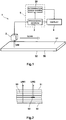
- an ultrasonic testing device 1 includes a probe 2 which generates an ultrasonic sound wave and receives a reflected sound wave, a processing section 3 which generates data for testing (inspection) based on the reflected sound wave received in the probe 2, and a display 4 which displays an image.
- the probe 2 may be an integrated one for generating the ultrasonic sound wave and receiving the reflected sound wave, or may be separately provided for generating the ultrasonic sound wave and receiving the reflected sound wave.
- the processing section 3 is one of functional blocks constituting a computer 5 as described later.
- the probe 2 When ultrasonic testing of a composite material component 50 is conducted using the ultrasonic testing device 1, the probe 2 is moved along an upper surface 51 of the composite material component 50 to scan the composite material component 50. The probe 2 is moved within, for example, a plane parallel to the upper surface 51. During scanning, the probe 2 generates an ultrasonic sound wave in a direction from the upper surface 51 of the composite material component 50 toward a bottom surface 52 of the composite component 50 (see arrow UW). The generated ultrasonic sound wave travels through an interior of the composite material component 50 in a thickness direction thereof.
- the ultrasonic sound wave is reflected by the bottom surface 52 of the composite material component 50 (see arrow UW1). If a flaw 53 is present on the path, the ultrasonic sound wave is reflected by a portion where that flaw is present (see arrow UW2). The reflected sound wave travels through the interior of the composite material component 50 again toward the upper surface 51 in the thickness direction thereof, and is received in the probe 2 (see Fig. 1 ).
- the processing section 3 generates data relating to plural kinds of indices based on the reflected sound wave received in the probe 2. For example, the processing section 3 generates data of signal intensity (amplitude) of the reflected sound wave and data of TOF that passes from when the ultrasonic sound wave is generated until the reflected sound wave is received, for each scan position of the probe 2.
- the TOF corresponding to the flaw portion is shorter than that corresponding to a healthy portion. Therefore, with reference to data of TOF for each scan position, it can be detected in which location the flaw portion is present within the scanned region.
- a travel distance of the ultrasonic sound wave can be derived from the TOF and a sound velocity. Therefore, it can be detected in which location the internal flaw is present in the thickness direction of the composite material component 50.
- the FRP which is a typical example of a composite material includes plate-shaped fibrous layers laminated together and bonded together.
- Examples of the internal flaws which may be present in the FRP are delamination, void, porosity, inclusion, etc..
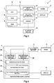
- the computer 5 including the processing section 3 is configured to incorporate a determination assist system 20 which generates a determination image used for identifying the kind and degree of the internal flaws.
- the computer 5 includes a CPU 7, a ROM 8, RAM9, an input interface 10, an output interface 11, and a driver 12, which are interconnected via a bus 6.
- the probe 2 is coupled to the input interface 10.
- Information based on the reflected sound wave received in the probe 2 is input to the computer 5, and is stored in the RAM 9 as necessary.
- the display 4 is coupled to the output interface 11. Image information generated in the CPU 7 can be output from the computer 5 to the display 4.
- the display 4 is capable of displaying the image information from the computer 5.
- the ROM 8 and the RAM 9 are configured to store programs to be executed by the CPU 7. Examples of such programs are a data generating program executed to appropriately process the input information from the probe 2 to acquire data of the signal intensity of the reflected sound wave and data of the TOF, for each scan position, a determination assist program executed to generate the above the determination image based on these data, etc..
- a method of providing the determination assist program to the computer 5 is not particularly limited.
- the determination assist program may be provided to the computer 5 via an electric communication line (not shown) such as Internet, or the program provided in this way may be stored in a memory area according to a predetermined installation procedure.
- the computer 5 allows the driver 12 to read the programs stored in storage media 15 such as CD or DVD. Therefore, the determination assist program stored in the storage medium 15 can be stored in the memory area according to a predetermined installation procedure.
- the computer 5 includes the processing section 3 and the determination assist system 20 as the functional blocks which are able to execute the data generating program and the determination assist program.
- the determination assist system 20 includes a first image generating section 21, a second image generating section 22, a differentiation section 23, a binarization section 24, and a determination image processing section 25 as functional blocks based on a procedure content of the determination assist program. That is, the operation of each of the functional blocks 21 to 25 is equivalent to the content of each procedure commanded by the determination assist program.
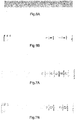
- step S1 the procedure (i.e., determination assist method of the present invention) commanded by the determination assist program shown in Fig. 5 will be described.
- the first image generating section 21 in the computer 5 generates "C-AMP image” based on the data of the signal intensity of the reflected sound wave for each scan position which is generated by the processing section 3.
- step S2 the second image generating section 22 generates "C-TOF image” based on the data of the TOF for each scan position which is generated by the processing section 3.
- the order of step S1 and step S2 is not particularly limited.
- the C-AMP image and the C-TOF image are planar images corresponding to a scan range of the probe, respectively.
- the C-AMP image and the C-TOF image are gradational images.
- white-black gradation is applied to the images in Fig. 6 as a form of gradation, another form (e.g., gradation of spectrum, etc.) may be applied to the image.
- the number of gray scales (tones) is not particularly limited.
- the C-AMP image is generated in such a manner that a darker color is assigned to a pixel corresponding to each scan position, when the signal intensity of the corresponding reflected sound wave has a smaller value. This results in a planar gradational image as a whole.
- the signal intensity of the reflected sound wave is higher when the sound wave is reflected by the flaw portion than when the sound wave is reflected by the bottom surface, although it may depend on parameters used in inspection.
- the C-TOF image is generated in such a manner that a darker color is assigned to a pixel corresponding to each scan position, when the corresponding TOF has a smaller value. This results in a planar gradational image as a whole.
- the TOF is shorter when the sound wave is reflected by the flaw portion than when the sound wave is reflected by the bottom surface.
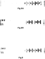
- step S3 the differentiation section 23 differentiates the C-AMP image to generate "differential C-AMP image,” and differentiates the C-TOF image to generate "differential C-TOF image.”
- the differential C-AMP image and the differential C-TOF image are gradational images.
- the C-AMP differentiation image and the C-TOF differentiation image are each generated in such a manner that a darker color is assigned when a gradational change between adjacent pixels is greater. This results in planar gradational images as a whole. Therefore, roughly, in each of the differential C-AMP image and the differential C-TOF image, an edge of a region displayed as a lighter color in the corresponding original image, i.e., an edge of a region for which it is estimated that the internal flaw is present is displayed as a darker color.
- step S4 the binarization section 24 binarizes the "differential C-AMP image” to generate "binary C-AMP image,” and binarizes the differential C-TOF image to generate "binary C-TOF image.”
- each of the binary C-AMP image and the binary C-TOF image are generated in such a manner that it is determined whether or not a gray scale (tone) of each pixel in the corresponding differential image is not less than a threshold, and a pixel which is not less than the threshold and a pixel which is less than the threshold can be identified such that they are distinguished from each other.
- a gray scale (tone) of each pixel in the corresponding differential image is not less than a threshold
- a pixel which is not less than the threshold and a pixel which is less than the threshold can be identified such that they are distinguished from each other.
- step S5 the determination image generating section 25 superposes the binary C-AMP image and the binary C-TOF image together, to generate the determination image.
- a pixel which is determined as a pixel which is not less than a threshold, among pixels constituting the binary C-AMP image is "first pixel”
- a pixel which is determined as a pixel which is less than the threshold, among pixels constituting the binary C-AMP image is "second pixel”
- a pixel which is determined as a pixel which is not less than a threshold, among pixels constituting the binary C-TOF image is "third pixel”
- a pixel which is determined as a pixel which is less than the threshold, among pixels constituting the binary C-TOF image is "fourth pixel.”
- the determination image generating section 25 superposes the binary C-AMP image and the binary C-TOF image together, to generate the determination image in such a manner that a region where the first pixel of the binary C-AMP image and the third pixel of the binary C-TOF image overlap with each other, a region where the first pixel of the binary C-AMP image and the fourth pixel of the binary C-TOF image overlap with each other, a region where the second pixel of the binary C-AMP image and the third pixel of the binary C-TOF image overlap with each other, and a region where the second pixel of the binary C-AMP image and the fourth pixel of the binary C-TOF image overlap with each other, can be identified such that they are distinguished from each other.
- the wordings "identified such that they are distinguished from each other” means that the above stated four regions are displayed by different colors, by different patterns, or in another way so that the inspector can easily visually distinguish these four regions when the determination image is displayed on the display 4.
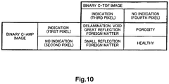
- Fig. 10 shows a correspondence among the four regions displayed to be identified such that they are distinguished from each other, and the kinds of the internal flaws of the composite material component 50.
- the regions indicating the edges of the internal flaws in the two binary images overlap with each other.
- the inspector can easily identify within this identified region, the delamination, the void, or the inclusion which is the presence of a foreign matter which is high in signal intensity of the reflected sound wave, among the internal flaws.
- the region indicating the edge of the flaw portion in the binary C-AMP image and the region indicating the healthy portion in the binary C-TOF image overlap with each other.
- the region indicating the healthy portion in the binary C-AMP image and the region indicating the edge of the flaw portion in the binary C-TOF image overlap with each other.
- the regions indicating the healthy portions in the two binary images overlap with each other.
- the inspector can easily identify this region as being healthy so long as this region is not a region located inward relative to any of the above stated three regions.
- the kind of the internal flaws can be identified easily using one piece of determination image. Because of this, time required to identify the internal flaw can be reduced significantly, and an inspection burden of the ultrasonic testing can be lessened significantly.
- the determination image displays the edge of the internal flaw. Therefore, a planar area of the internal flaw can be derived easily, and how severe the internal flaw is can be identified easily for each kind of the internal flaws. This makes it possible to significantly lessen the inspection burden of the ultrasonic testing of the composite material structure, and determine whether or not the composite material component is healthy, without depending on the inspector's skill.
- the composite material component frequently has a non-uniform thickness.
- its upper surface and its bottom surface are not parallel in some cases. Because of this, when the probe is moved within a plane parallel to the upper surface to scan the composite material component, and generates the ultrasonic sound wave in a normal line direction of the upper surface, then the signal intensity of the reflected sound wave is low in a portion whose thickness changes, because the bottom surface is inclined with respect to the upper surface even though that portion is healthy. When the thickness is smaller, the TOF of even the healthy portion is shorter.
- the inspector In a case where the internal flaw is identified with reference to the binary C-AMP image and the binary C-TOF image, in a conventional method, the inspector must correctly determine whether gray scale (tone) display performed according to the signal intensity of the reflected sound wave or the TOF is due to a change in the thickness or presence of the internal flaw.
- the determination image is generated after the C-AMP image and the C-TOF image have been subjected to the differentiation process and the binarization process.
- the corresponding signal intensity or TOF increases or decreases gradually, and therefore, a lighter color is assigned to this portion in the differential image.
- proper thresholds are set to prevent the increase or decrease in the signal intensity or TOF due to such a thickness change from being extracted as the first pixel and the third pixel indicating the presence of the internal flaw. In this way, in the binary images, only the edge of the internal flaw can be extracted as the first and third pixels. Therefore, in the present embodiment, even when a composite material component whose thickness changes is tested, the internal flaw can be identified correctly.
- a useful determination image can be generated by combining an image generated by binarizing the C-TOF image or the C-AMP image before differentiation, with the binary C-AMP image or the binary C-TOF image generated by binarizing the differential C-AMP image or the differential C-TOF image.
- the probe 2 is moved in a range slightly wider than a range defined by an end of the upper surface 51 of the composite material component 50 in a state where the probe 2 faces the upper surface 51 of the composite material component 50, and transmits and receives the ultrasonic sound wave in a region outside the end of the composite material component 50.
- the differential image of the present embodiment is generated to display the edge of the internal flaw clearly.
- a boundary line i.e., end of the composite material component
- the inside region of the composite material component 50 and the outside region of the composite material component 50 appears according to a change in the value of the signal intensity of the reflected sound wave and a change in the value of the TOF.
- the differentiation section 23 generates each differential image in such a manner that the image generated by differentiating the original planar image is combined with a planar image newly created by setting a gate which captures only a signal of the reflected sound wave from the upper surface to determine presence/absence of a component in step S1, to make compensation so that a pixel expressed as the end of the composite material component in the original planar image is displayed as a lighter color.
- a pixel expressed as a darker color as corresponding to the end of the composite material component 50 is displayed as a lighter color, and only an internal flaw present in the vicinity of the end is displayed as a darker color. Therefore, by generating the determination image by using the compensated differential C-AMP image and the compensated differential C-TOF image, the internal flaw in the vicinity of the end can be identified correctly, with reference to the determination image.
- the differentiation section 23 differentiates the C-AMP image in such a manner that compensation is made for the value of the signal intensity in the vicinity of the end so that the value of the signal intensity of the reflected sound wave changes sensitively at the boundary line which is the end of the composite material component 50, i.e., between the inside region of the composite material component 50 and the outside region of the composite material component 50.
- This compensation method is not particularly limited.
- An intermediate point M between a point A in the inside region at which a value A' of the signal intensity starts to change and a point B in the outside region at which a value B' of the signal intensity starts to change may be derived, and compensation may be made so that a value of signal intensity in a range from the point A to the intermediate point M becomes equal to the value A' of the signal intensity in the region inward relative to the point A.
- the C-AMP image generated after compensation is made in this way makes it possible to reduce a portion displayed as a darker color in a differential image, due to the end (in the present example, intermediate point M) of the composite material component, and improve a compensation accuracy of the differentiation image.
- a gate may be set immediately below the upper surface to improve a resolution in the vicinity of the upper surface 51, in addition to the gate which captures the whole signal including the signal intensity of the sound wave reflected by the bottom surface 52.
- a planar image generated based on the gate added newly may be subjected to only the binarization process without the differentiation process, and the resulting image may be used to derive the determination image.
- the porosity might appear in the binary C-AMP image. Therefore, with reference to the determination image generated based on the binary C-AMP image, the porosity can be identified.
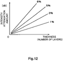
- the degree of porosity (hereinafter referred to as "porosity rate”) is derived in such a manner that a difference between the signal intensity of the reflected sound wave from the bottom surface and the signal intensity of the reflected sound wave from a portion in which the porosity is present is calculated. Then, thickness information is obtained from the C-TOF image. Then, with reference to a porosity rate conversion graph shown in Fig. 12 , the porosity rate is derived based on the difference in signal intensity and the thickness (or the number of layers) of the composite material component.
- portion from which no reflected signal is obtained from the bottom surface is referred to as "portion from which no reflected signal is obtained from the bottom surface.”
- the thickness of the portion from which no reflected signal is obtained from the bottom surface is derived by interpolation. Based on the thickness information derived by the interpolation and the difference in the signal intensity, and with reference to the porosity rate conversion graph, the porosity rate is derived.
- the interpolation process allows the porosity rate to be identified correctly even when a level of the porosity rate is high. Thus, it can be determined whether or not the composite material component is healthy.
- the composite material component for use in aircraft often has a portion whose thickness changes. If the portion from which no reflected signal is obtained from the bottom surface is formed in the portion whose thickness changes, an interpolated portion of the bottom surface is preferably inclined with respect to the upper surface like the surrounding portion of the bottom surface. Thus, even when the portion from which no reflected signal is obtained from the bottom surface is formed in the portion whose thicknesses changes, the porosity rate can be identified correctly.
- the bottom surface is not parallel to the upper surface.
- the intensity of the reflected signal is lower than that of a portion in which the bottom surface is parallel to the upper surface even if these portions are equal in thickness.
- different porosity rate conversion graphs are preferably utilized depending on the inclination angle of the bottom surface of the composite material component with respect to its upper surface. This makes it possible to derive the porosity rate correctly even in cases where a certain composite material component includes different structures or shapes.
- the porosity rate conversion graph set for each portion may include a graph used for deriving zero as the porosity rate irrespective of a thickness difference and a signal difference. This graph applied to a predetermined portion can serve as a mask which prevents the porosity rate from being evaluated for the predetermined portion.
- a test condition application map is used (see Fig. 13 ).
- a thickness map may be pre-stored in a memory area, instead of thickness information derived from the C-TOF image.
- the thickness map may be contained in the test condition application map.
- a planar image may be generated in such a manner that the planar image is displayed by gray scales (tones) according to the porosity rate.
- a magnitude of the porosity rate can be displayed as a contour representation shown in Fig. 14 .
- the planar image displayed as the contour representation and the C-AMP image may be superposed together.
- the present invention is advantageously applied to ultrasonic testing of large-sized components such as composite material components for use in aircraft.
Landscapes
- Physics & Mathematics (AREA)
- Biochemistry (AREA)
- Health & Medical Sciences (AREA)
- Life Sciences & Earth Sciences (AREA)
- Chemical & Material Sciences (AREA)
- Analytical Chemistry (AREA)
- General Health & Medical Sciences (AREA)
- General Physics & Mathematics (AREA)
- Immunology (AREA)
- Pathology (AREA)
- Acoustics & Sound (AREA)
- Engineering & Computer Science (AREA)
- Signal Processing (AREA)
- Investigating Or Analyzing Materials By The Use Of Ultrasonic Waves (AREA)
Claims (18)
- Bestimmungsunterstützungssystem zur Verwendung bei der Ultraschallprüfung, wobei das System dazu angepasst ist, ein Bestimmungsbild zu erzeugen, das verwendet wird, um zu bestimmen, ob eine Komponente aus Verbundmaterial gesund ist oder nicht, und zwar basierend auf Daten mehrerer Arten von Prüfindizes, die in einer Ultraschallprüfvorrichtung (1) erhalten wurden, wobei das Bestimmungsunterstützungssystem durch Folgendes gekennzeichnet ist:einen ersten Bilderzeugungsabschnitt (21), der dazu angepasst ist, ein erstes planares Bild zu erzeugen, bei dem es sich um ein Gradationsbild handelt, und zwar basierend auf Daten einer Signalintensität einer reflektierten Schallwelle als einen ersten Prüfindex;einen zweiten Bilderzeugungsabschnitt (22), der dazu angepasst ist, ein zweites planares Bild zu erzeugen, bei dem es sich um ein Gradationsbild handelt, und zwar basierend auf Daten einer Propagationszeit einer Ultraschallwelle als einen zweiten Prüfindex;einen Differenzierungsabschnitt (23), der dazu angepasst ist, das erste planare Bild zu differenzieren, um ein erstes Differenzialbild zu erzeugen, das als unterschiedliche Töne ausgedrückt wird, die jeweils unterschiedlichen Werten entsprechen, und das zweite planare Bild zu differenzieren, um ein zweites Differenzialbild zu erzeugen, das als unterschiedliche Töne ausgedrückt wird, die jeweils Differenzialwerten entsprechen;einen Binärisierungsabschnitt (24), der zu Folgendem angepasst ist: Binarisieren des ersten Differenzialbildes, um ein erstes Binärbild zu erzeugen, das einen ersten Bereich enthält, in dem eine Gradation nicht kleiner als ein erster Schwellenwert innerhalb des ersten Differenzialbildes ist, und einen zweiten Bereich enthält, in dem die Gradation kleiner als der erste Schwellenwert innerhalb des ersten Differenzialbildes ist, und Binarisieren des zweiten Differenzialbildes, um ein zweites Binärbild zu erzeugen, das einen dritten Bereich enthält, in dem eine Gradation nicht kleiner als ein zweiter Schwellenwert innerhalb des zweiten Differenzialbildes ist, und einen vierten Bereich enthält, in dem die Gradation kleiner als der zweite Schwellenwert innerhalb des zweiten Differenzialbildes ist; undeinen Bestimmungsbild-Erzeugungsabschnitt (25), der dazu angepasst ist, das Bestimmungsbild basierend auf dem ersten Binärbild und dem zweiten Binärbild zu erzeugen,wobei der Bestimmungsbild-Erzeugungsabschnitt (25) dazu konfiguriert ist, das Bestimmungsbild auf eine solche Art und Weise zu erzeugen, dass das erste Binärbild und das zweite Binärbild einander überlagern; undin dem Bestimmungsbild ein Bereich, in dem sich der erste Bereich und der dritte Bereich überlappen, ein Bereich, in dem sich der erste Bereich und der vierte Bereich überlappen, ein Bereich, in dem sich der zweite Bereich und der dritte Bereich überlappen; und ein Bereich, in dem sich der zweite Bereich und der vierte Bereich überlappen, so identifiziert werden, dass die Bereiche voneinander unterschieden werden.
- Bestimmungsunterstützungssystem zur Verwendung bei der Ultraschallprüfung nach Anspruch 1,
wobei der erste Bilderzeugungsabschnitt (21) dazu konfiguriert ist, das erste planare Bild zu erzeugen, nachdem ein Ausgleich durchgeführt worden ist, der bewirkt, dass die Daten des ersten Prüfindexes in der unmittelbaren Nähe eines Endabschnitts der Komponente aus Verbundmaterial sich empfindlich ändern. - Bestimmungsunterstützungssystem zur Verwendung bei der Ultraschallprüfung nach Anspruch 1 oder 2, das weiterhin Folgendes umfasst:einen dritten Bilderzeugungsabschnitt, der dazu angepasst ist, ein drittes planares Bild zu erzeugen, bei dem es sich um ein Gradationsbild handelt, und zwar basierend auf Daten eines dritten Prüfindexes; undein Ausgleichsabschnitt, der dazu angepasst ist, einen Ausgleich des ersten Differenzialbildes auf eine solche Art und Weise durchzuführen, dass das erste Differenzialbild und das dritte planare Bild einander überlagern, um einen höheren Differenzialwert aufzuheben, der aus dem ersten Differenzialbild in der unmittelbaren Nähe eines Endabschnitts der Komponente aus Verbundmaterial erzeugt wurde;wobei der Binärisierungsabschnitt (24) dazu konfiguriert ist, das erste Binärbild basierend auf dem ausgeglichenen ersten Differenzialbild zu erzeugen.
- Bestimmungsunterstützungssystem zur Verwendung bei der Ultraschallprüfung nach Anspruch 3,
wobei es sich bei dem dritten Prüfindex um die Signalintensität der reflektierten Schallwelle handelt. - Bestimmungsunterstützungssystem zur Verwendung bei der Ultraschallprüfung, wobei das System dazu konfiguriert ist, ein Bestimmungsbild zu erzeugen, das verwendet wird, um zu bestimmen, ob eine Komponente aus Verbundmaterial gesund ist oder nicht, und zwar basierend auf Daten mehrerer Arten von Prüfindizes, die in einer Ultraschallprüfvorrichtung (1) erhalten wurden, wobei das Bestimmungsunterstützungssystem durch Folgendes gekennzeichnet ist:einen ersten Bilderzeugungsabschnitt (21), der dazu konfiguriert ist, ein erstes planares Bild zu erzeugen, bei dem es sich um ein Gradationsbild handelt, und zwar basierend auf Daten einer Signalintensität einer reflektierten Schallwelle als einen ersten Prüfindex;einen zweiten Bilderzeugungsabschnitt (22), der dazu konfiguriert ist, ein zweites planares Bild zu erzeugen, bei dem es sich um ein Gradationsbild handelt, und zwar basierend auf Daten einer Propagationszeit einer Ultraschallwelle als einen zweiten Prüfindex;einen Differenzierungsabschnitt (23), der dazu konfiguriert ist, eines aus dem ersten planaren Bild und dem zweiten planaren Bild zu differenzieren, um ein Differenzialbild zu erzeugen, das als unterschiedliche Töne ausgedrückt wird, die jeweils unterschiedlichen Werten entsprechen;einen Binärisierungsabschnitt (24), der zu Folgendem angepasst ist: Binarisieren des Differenzialbildes, um ein erstes Binärbild zu erzeugen, das einen ersten Bereich enthält, in dem eine Gradation nicht kleiner als ein erster Schwellenwert innerhalb des ersten Differenzialbildes ist, und einen zweiten Bereich enthält, in dem die Gradation kleiner als der erste Schwellenwert innerhalb des Differenzialbildes ist, und Binarisieren des anderen aus dem ersten planaren Bild und dem zweiten planaren Bild, um ein zweites Binärbild zu erzeugen, das einen dritten Bereich enthält, in dem eine Gradation nicht kleiner als ein zweiter Schwellenwert innerhalb des anderen aus dem ersten planaren Bild und dem zweiten planaren Bild ist, und einen vierten Bereich enthält, in dem die Gradation kleiner als der zweite Schwellenwert innerhalb des anderen aus dem ersten planaren Bild und dem zweiten planaren Bild ist; undeinen Bestimmungsbild-Erzeugungsabschnitt (25), der dazu angepasst ist, das Bestimmungsbild basierend auf dem ersten Binärbild und dem zweiten Binärbild zu erzeugen,wobei der Bestimmungsbild-Erzeugungsabschnitt (25) dazu konfiguriert ist, das Bestimmungsbild auf eine solche Art und Weise zu erzeugen, dass das erste Binärbild und das zweite Binärbild einander überlagern; undin dem Bestimmungsbild ein Bereich, in dem sich der erste Bereich und der dritte Bereich überlappen, ein Bereich, in dem sich der erste Bereich und der vierte Bereich überlappen, ein Bereich, in dem sich der zweite Bereich und der dritte Bereich überlappen, und ein Bereich, in der sich der zweite Bereich und der vierte Bereich überlappen, so identifiziert werden, dass die Bereiche voneinander unterschieden werden.
- Bestimmungsunterstützungssystem zur Verwendung bei der Ultraschallprüfung nach Anspruch 5,
wobei der erste Bilderzeugungsabschnitt (21) dazu angepasst ist, das erste planare Bild zu erzeugen, nachdem ein Ausgleich durchgeführt worden ist, der bewirkt, dass die Daten des ersten Prüfindexes in der unmittelbaren Nähe eines Endabschnitts der Komponente aus Verbundmaterial sich empfindlich ändern. - Bestimmungsunterstützungssystem zur Verwendung bei der Ultraschallprüfung nach Anspruch 5 oder 6, das weiterhin Folgendes umfasst:einen dritten Bilderzeugungsabschnitt, der dazu konfiguriert ist, ein drittes planares Bild zu erzeugen, bei dem es sich um ein Gradationsbild handelt, und zwar basierend auf Daten eines dritten Prüfindexes; undein Ausgleichsabschnitt, der dazu konfiguriert ist, einen Ausgleich des Differenzialbildes auf eine solche Art und Weise durchzuführen, dass das Differenzialbild und das dritte planare Bild einander überlagern, um einen höheren Differenzialwert aufzuheben, der aus dem Differenzialbild in der unmittelbaren Nähe eines Endabschnitts der Komponente aus Verbundmaterial erzeugt wurde;wobei der Binärisierungsabschnitt (24) dazu konfiguriert ist, das erste Binärbild basierend auf dem ausgeglichenen Differenzialbild zu erzeugen.
- Bestimmungsunterstützungssystem zur Verwendung bei der Ultraschallprüfung nach Anspruch 7,
wobei es sich bei dem dritten Prüfindex um die Signalintensität der reflektierten Schallwelle handelt. - Bestimmungsunterstützungsverfahren zur Verwendung bei der Ultraschallprüfung, wobei ein Bestimmungsbild erzeugt wird, das verwendet wird, um zu bestimmen, ob eine Komponente aus Verbundmaterial gesund ist oder nicht, und zwar basierend auf Daten mehrerer Arten von Prüfindizes, die in einer Ultraschallprüfvorrichtung (1) erhalten wurden, wobei das Bestimmungsunterstützungsverfahren durch die folgenden Schritte gekennzeichnet ist:Erzeugen eines ersten planaren Bildes, bei dem es sich um ein Gradationsbild handelt, und zwar basierend auf Daten einer Signalintensität einer reflektierten Schallwelle als einen ersten Prüfindex;Erzeugen eines zweiten planaren Bildes, bei dem es sich um ein Gradationsbild handelt, und zwar basierend auf Daten einer Propagationszeit einer Ultraschallwelle als einen zweiten Prüfindex;Differenzieren des ersten planaren Bildes, um ein erstes Differenzialbild zu erzeugen, das als unterschiedliche Töne ausgedrückt wird, die jeweils unterschiedlichen Werten entsprechen, und Differenzieren des zweiten planaren Bildes, um ein zweites Differenzialbild zu erzeugen, das als unterschiedliche Töne ausgedrückt wird, die jeweils Differenzwerten entsprechen;Binarisieren des ersten Differenzialbildes, um ein erstes Binärbild zu erzeugen, das einen ersten Bereich enthält, in dem eine Gradation nicht kleiner als ein erster Schwellenwert innerhalb des ersten Differenzialbildes ist, und einen zweiten Bereich enthält, in dem die Gradation kleiner als der erste Schwellenwert innerhalb des ersten Differenzialbildes ist, und Binarisieren des zweiten Differenzialbildes, um ein zweites Binärbild zu erzeugen, das einen dritten Bereich enthält, in dem eine Gradation nicht kleiner als ein zweiter Schwellenwert innerhalb des zweiten Differenzialbildes ist, und einen vierten Bereich enthält, in dem die Gradation kleiner als der zweite Schwellenwert innerhalb des zweiten Differenzialbildes ist; undErzeugen des Bestimmungsbildes basierend auf dem ersten Binärbild und dem zweiten Binärbild,wobei in dem Schritt des Erzeugens des Bestimmungsbildes das Bestimmungsbild auf eine solche Art und Weise erzeugt wird, dass das erste Binärbild und das zweite Binärbild einander überlagern; undin dem Bestimmungsbild ein Bereich, in dem sich der erste Bereich und der dritte Bereich überlappen, ein Bereich, in dem sich der erste Bereich und der vierte Bereich überlappen, ein Bereich, in dem sich der zweite Bereich und der dritte Bereich überlappen, und ein Bereich, in dem sich der zweite Bereich und der vierte Bereich überlappen, so identifiziert werden können, dass die Bereiche voneinander unterschieden werden.
- Bestimmungsunterstützungsverfahren zur Verwendung bei der Ultraschallprüfung nach Anspruch 9,
wobei in dem Schritt des Erzeugens des ersten planaren Bildes das erste planare Bild erzeugt wird, nachdem ein Ausgleich durchgeführt worden ist, der bewirkt, dass die Daten des ersten Prüfindexes in der unmittelbaren Nähe eines Endabschnitts der Komponente aus Verbundmaterial sich empfindlich ändern. - Bestimmungsunterstützungsverfahren zur Verwendung bei der Ultraschallprüfung nach Anspruch 9 oder 10, wobei der Schritt des Erzeugens des ersten Differenzialbildes und des zweiten Differenzialbildes Folgendes umfasst:Erzeugen eines dritten planaren Bildes, bei dem es sich um ein Gradationsbild handelt, und zwar basierend auf Daten eines dritten Prüfindexes; undDurchführen eines Ausgleichs des ersten Differenzialbildes auf eine solche Art und Weise, dass das erste Differenzialbild und das dritte planare Bild einander überlagern, um einen höheren Differenzialwert aufzuheben, der aus dem ersten Differenzialbild in der unmittelbaren Nähe eines Endabschnitts der Komponente aus Verbundmaterial erzeugt wurde;wobei in dem Schritt des Erzeugens des ersten Binärbildes und des zweiten Binärbildes das erste Binärbild basierend auf dem ausgeglichenen ersten Differenzialbild erzeugt wird.
- Bestimmungsunterstützungsverfahren zur Verwendung bei der Ultraschallprüfung nach Anspruch 11,
wobei es sich bei dem dritten Prüfindex um die Signalintensität der reflektierten Schallwelle handelt und bei dem zweiten Prüfindex um eine Propagationszeit einer Ultraschallwelle handelt. - Bestimmungsunterstützungsverfahren zur Verwendung bei der Ultraschallprüfung, wobei ein Bestimmungsbild erzeugt wird, das verwendet wird, um zu bestimmen, ob eine Komponente aus Verbundmaterial gesund ist oder nicht, und zwar basierend auf Daten mehrerer Arten von Prüfindizes, die in einer Ultraschallprüfvorrichtung (1) erhalten wurden, wobei das Bestimmungsunterstützungsverfahren durch die folgenden Schritte gekennzeichnet ist:Erzeugen eines ersten planaren Bildes, bei dem es sich um ein Gradationsbild handelt, und zwar basierend auf Daten einer Signalintensität einer reflektierten Schallwelle als einen ersten Prüfindex;Erzeugen eines zweiten planaren Bildes, bei dem es sich um ein Gradationsbild handelt, und zwar basierend auf Daten einer Propagationszeit einer Ultraschallwelle als einen zweiten Prüfindex;Differenzieren eines aus dem ersten planaren Bild und dem zweiten planaren Bild, um ein erstes Differenzialbild zu erzeugen, das als unterschiedliche Töne ausgedrückt wird, die jeweils unterschiedlichen Werten entsprechen;Binarisieren des Differenzialbildes, um ein erstes Binärbild zu erzeugen, das einen ersten Bereich enthält, in dem eine Gradation nicht kleiner als ein erster Schwellenwert innerhalb des Differenzialbildes ist, und einen zweiten Bereich enthält, in dem die Gradation kleiner als der erste Schwellenwert innerhalb des Differenzialbildes ist, und Binarisieren des anderen aus dem ersten planaren Bild und dem zweiten planaren Bild, um ein zweites Binärbild zu erzeugen, das einen dritten Bereich enthält, in dem eine Gradation nicht kleiner als ein zweiter Schwellenwert innerhalb des anderen aus dem ersten planaren Bild und dem zweiten planaren Bild ist, und einen vierten Bereich enthält, in dem die Gradation kleiner als der zweite Schwellenwert innerhalb des anderen aus dem ersten planaren Bild und dem zweiten planaren Bild ist; undErzeugen des Bestimmungsbildes basierend auf dem ersten Binärbild und dem zweiten Binärbild,wobei in dem Schritt des Erzeugens des Bestimmungsbildes das Bestimmungsbild auf eine solche Art und Weise erzeugt wird, dass das erste Binärbild und das zweite Binärbild einander überlagern; undin dem Bestimmungsbild ein Bereich, in dem sich der erste Bereich und der dritte Bereich überlappen, ein Bereich, in dem sich der erste Bereich und der vierte Bereich überlappen, ein Bereich, in dem sich der zweite Bereich und der dritte Bereich überlappen, und ein Bereich, in dem sich der zweite Bereich und der vierte Bereich überlappen, so identifiziert werden, dass die Bereiche voneinander unterschieden werden.
- Bestimmungsunterstützungsverfahren zur Verwendung bei der Ultraschallprüfung nach Anspruch 13,
wobei in dem Schritt des Erzeugens des ersten planaren Bildes das erste planare Bild erzeugt wird, nachdem ein Ausgleich durchgeführt worden ist, der bewirkt, dass die Daten des ersten Prüfindexes in der unmittelbaren Nähe eines Endabschnitts der Komponente aus Verbundmaterial sich empfindlich ändern. - Bestimmungsunterstützungsverfahren zur Verwendung bei der Ultraschallprüfung nach Anspruch 13 oder 14, wobei der Schritt des Erzeugens des Differenzialbildes Folgendes umfasst:Erzeugen eines dritten planaren Bildes, bei dem es sich um ein Gradationsbild handelt, und zwar basierend auf Daten eines dritten Prüfindexes; undDurchführen eines Ausgleichs für das Differenzialbild auf eine solche Art und Weise, dass das Differenzialbild und das dritte planare Bild einander überlagern, um einen höheren Differenzialwert aufzuheben, der aus dem Differenzialbild in der unmittelbaren Nähe eines Endabschnitts der Komponente aus Verbundmaterial erzeugt wurde;wobei in dem Schritt des Erzeugens des ersten Binärbildes und des zweiten Binärbildes das erste Binärbild basierend auf dem ausgeglichenen Differenzialbild erzeugt wird.
- Bestimmungsunterstützungsverfahren zur Verwendung bei der Ultraschallprüfung nach Anspruch 15,
wobei es sich bei dem dritten Prüfindex um die Signalintensität der reflektierten Schallwelle handelt. - Bestimmungsunterstützungscomputerprogramm zur Verwendung bei der Ultraschallprüfung, das bei Ausführung bewirkt, dass ein Computer (5) das Verfahren nach einem der Ansprüche 9 bis 16 durchführt.
- Computerlesbares Speichermedium, das das Bestimmungsunterstützungscomputerprogramm nach Anspruch 17 beinhaltet.
Priority Applications (1)
| Application Number | Priority Date | Filing Date | Title |
|---|---|---|---|
| EP17000944.3A EP3236254B1 (de) | 2009-10-05 | 2010-10-04 | Ultraschsystem und verfahren zur bestimmung von porosität in verbundmaterialien. |
Applications Claiming Priority (2)
| Application Number | Priority Date | Filing Date | Title |
|---|---|---|---|
| JP2009231655 | 2009-10-05 | ||
| PCT/JP2010/005932 WO2011043050A1 (ja) | 2009-10-05 | 2010-10-04 | 超音波探傷検査の判定支援装置、判定支援方法、判定支援プログラム、及び該判定支援プログラムを記録したコンピュータ読取可能な記録媒体 |
Related Child Applications (2)
| Application Number | Title | Priority Date | Filing Date |
|---|---|---|---|
| EP17000944.3A Division-Into EP3236254B1 (de) | 2009-10-05 | 2010-10-04 | Ultraschsystem und verfahren zur bestimmung von porosität in verbundmaterialien. |
| EP17000944.3A Division EP3236254B1 (de) | 2009-10-05 | 2010-10-04 | Ultraschsystem und verfahren zur bestimmung von porosität in verbundmaterialien. |
Publications (3)
| Publication Number | Publication Date |
|---|---|
| EP2487487A1 EP2487487A1 (de) | 2012-08-15 |
| EP2487487A4 EP2487487A4 (de) | 2017-08-30 |
| EP2487487B1 true EP2487487B1 (de) | 2020-12-02 |
Family
ID=43856534
Family Applications (2)
| Application Number | Title | Priority Date | Filing Date |
|---|---|---|---|
| EP10821727.4A Active EP2487487B1 (de) | 2009-10-05 | 2010-10-04 | Bestimmungsunterstützungsvorrichtung für ultraschallprüfungen, bestimmungsunterstützungsverfahren, bestimmungsunterstützungsprogramm und computerlesbares aufzeichnungsmedium mit dem darauf aufgezeichneten bestimmungsunterstützungsprogramm |
| EP17000944.3A Active EP3236254B1 (de) | 2009-10-05 | 2010-10-04 | Ultraschsystem und verfahren zur bestimmung von porosität in verbundmaterialien. |
Family Applications After (1)
| Application Number | Title | Priority Date | Filing Date |
|---|---|---|---|
| EP17000944.3A Active EP3236254B1 (de) | 2009-10-05 | 2010-10-04 | Ultraschsystem und verfahren zur bestimmung von porosität in verbundmaterialien. |
Country Status (4)
| Country | Link |
|---|---|
| US (2) | US8934703B2 (de) |
| EP (2) | EP2487487B1 (de) |
| JP (1) | JP5392731B2 (de) |
| WO (1) | WO2011043050A1 (de) |
Families Citing this family (18)
| Publication number | Priority date | Publication date | Assignee | Title |
|---|---|---|---|---|
| US9038470B1 (en) | 2012-08-07 | 2015-05-26 | The Boeing Company | Porosity inspection system for composite structures |
| US9595092B2 (en) * | 2013-05-10 | 2017-03-14 | The Boeing Company | Methods and systems for inspection of composite irregularities |
| US9360459B2 (en) | 2013-05-17 | 2016-06-07 | The Boeing Company | Porosity inspection system for composite structure with non-parallel surfaces |
| US9933393B2 (en) * | 2015-12-09 | 2018-04-03 | The Boeing Company | Apparatuses, methods, and systems for inspecting a composite end portion of a part |
| US10580135B2 (en) | 2016-07-14 | 2020-03-03 | Shanghai United Imaging Healthcare Co., Ltd. | System and method for splicing images |
| GB2572215A (en) | 2018-03-23 | 2019-09-25 | Short Brothers Ltd | Detection of kiss bonds within composite components |
| US11860131B2 (en) | 2020-03-30 | 2024-01-02 | Verifi Technologies, Llc | System and method for portable ultrasonic testing |
| US11726065B2 (en) | 2020-03-30 | 2023-08-15 | Verifi Technologies, Llc | System and method for real-time visualization of defects in a material |
| US12055519B2 (en) * | 2020-03-30 | 2024-08-06 | Verifi Technologies, Llc | System and method for real-time visualization of foreign objects within a material |
| US12535464B2 (en) | 2020-03-30 | 2026-01-27 | Baylor University | System and method for real-time visualization of defects in a material |
| US11686707B2 (en) | 2020-03-30 | 2023-06-27 | Verifi Technologies, Llc | System and method for real-time visualization of defects in a material |
| US11754529B2 (en) | 2020-03-30 | 2023-09-12 | Verifi Technologies, Llc | System and method for evaluating defects in a material |
| US12529683B2 (en) | 2020-03-30 | 2026-01-20 | Baylor University | System and method for real-time visualization of defects in a material |
| US20240393295A1 (en) * | 2020-03-30 | 2024-11-28 | Verifi Technologies, Llc | System and method for real-time visualization of foreign objects within a material |
| US12072315B2 (en) | 2020-03-30 | 2024-08-27 | Verifi Technologies, Llc | System and method for real-time visualization of defects in a material |
| US11650183B2 (en) | 2020-03-30 | 2023-05-16 | Verifi Technologies, Llc | System and method for real-time degree of cure evaluation in a material |
| KR20230173133A (ko) * | 2021-05-13 | 2023-12-26 | 세인트-고바인 세라믹스 앤드 플라스틱스, 인크. | 물체를 검사하기 위한 프로세스 및 시스템 |
| JP2024125596A (ja) * | 2023-03-06 | 2024-09-19 | 日本電波株式会社 | 打音検査結果出力装置および打音検査結果出力方法 |
Family Cites Families (28)
| Publication number | Priority date | Publication date | Assignee | Title |
|---|---|---|---|---|
| JPS5975140A (ja) * | 1982-10-22 | 1984-04-27 | Toshiba Corp | 欠陥検査装置及び方法 |
| JP2896385B2 (ja) * | 1989-09-14 | 1999-05-31 | 日本クラウトクレーマー株式会社 | 超音波検査方法及び装置 |
| JP3468573B2 (ja) | 1994-03-22 | 2003-11-17 | 積水化学工業株式会社 | 樹脂モルタル複合管の欠陥検査装置 |
| JPH0915218A (ja) * | 1995-06-30 | 1997-01-17 | Sumitomo Metal Ind Ltd | 板波超音波探傷方法及び装置 |
| US6947587B1 (en) * | 1998-04-21 | 2005-09-20 | Hitachi, Ltd. | Defect inspection method and apparatus |
| JPH11326580A (ja) | 1998-05-15 | 1999-11-26 | Toshiba Corp | シュラウド自動検査装置 |
| US7171038B2 (en) * | 2000-12-15 | 2007-01-30 | Kla-Tencor Technologies Corporation | Method and apparatus for inspecting a substrate |
| JP4614548B2 (ja) * | 2001-01-31 | 2011-01-19 | パナソニック株式会社 | 超音波診断装置 |
| EP1255224A1 (de) * | 2001-05-02 | 2002-11-06 | STMicroelectronics S.r.l. | System und Verfahren zur Analyse von Oberflächenfehlern |
| US6845178B1 (en) * | 2001-06-27 | 2005-01-18 | Electro Scientific Industries, Inc. | Automatic separation of subject pixels using segmentation based on multiple planes of measurement data |
| JP4172761B2 (ja) * | 2002-10-08 | 2008-10-29 | 大日本スクリーン製造株式会社 | 欠陥検査装置、欠陥検査方法およびプログラム |
| JP4322620B2 (ja) | 2003-06-17 | 2009-09-02 | 株式会社東芝 | 3次元超音波画像化装置 |
| JP2005181170A (ja) * | 2003-12-22 | 2005-07-07 | Jfe Steel Kk | 被覆材の密着性評価方法 |
| US20050286753A1 (en) * | 2004-06-25 | 2005-12-29 | Triant Technologies Inc. | Automated inspection systems and methods |
| JP4345930B2 (ja) * | 2005-01-28 | 2009-10-14 | Ykk株式会社 | 物品の外観検査装置 |
| US8206301B2 (en) * | 2005-02-01 | 2012-06-26 | Fujifilm Corporation | Ultrasonic imaging apparatus and ultrasonic image processing apparatus, method and program |
| US7804993B2 (en) * | 2005-02-28 | 2010-09-28 | Applied Materials South East Asia Pte. Ltd. | Method and apparatus for detecting defects in wafers including alignment of the wafer images so as to induce the same smear in all images |
| US8068665B2 (en) * | 2005-05-10 | 2011-11-29 | Kabushiki Kaisha Toshiba | 3D-image processing apparatus, 3D-image processing method, storage medium, and program |
| JP4704804B2 (ja) * | 2005-05-18 | 2011-06-22 | 株式会社名南製作所 | 木材の節探査方法及び装置及びプログラム |
| CN100460807C (zh) * | 2005-06-17 | 2009-02-11 | 欧姆龙株式会社 | 进行三维计测的图像处理装置及图像处理方法 |
| US7762120B2 (en) * | 2005-12-01 | 2010-07-27 | The Boeing Company | Tapered ultrasonic reference standard |
| US7389693B2 (en) * | 2006-02-15 | 2008-06-24 | General Electric Company | Methods and apparatus for porosity measurement |
| DE102006027132B4 (de) * | 2006-06-02 | 2010-04-15 | BAM Bundesanstalt für Materialforschung und -prüfung | Verfahren zum Detektieren von Fehlstellen in Betonbauteilen |
| KR100741985B1 (ko) * | 2006-07-13 | 2007-07-23 | 삼성전자주식회사 | 기준 이미지 설정 방법 및 장치, 및 이를 이용한 패턴 검사방법 및 장치 |
| US20080125653A1 (en) * | 2006-11-27 | 2008-05-29 | Board Of Regents, The University Of Texas System | Density and porosity measurements by ultrasound |
| US7617715B2 (en) * | 2006-12-21 | 2009-11-17 | The Boeing Company | Reference standard for ultrasonic measurement of porosity and related method |
| US20080229832A1 (en) * | 2007-02-16 | 2008-09-25 | Los Alamos National Security | Automatic time-of-flight selection for ultrasound tomography |
| FR2930344B1 (fr) | 2008-04-22 | 2010-05-21 | Eads Europ Aeronautic Defence | Procede et dispositif de controle non-destructif par ultrasons de la porosite d'une piece en materiau composite |
-
2010
- 2010-10-04 EP EP10821727.4A patent/EP2487487B1/de active Active
- 2010-10-04 EP EP17000944.3A patent/EP3236254B1/de active Active
- 2010-10-04 JP JP2011535274A patent/JP5392731B2/ja active Active
- 2010-10-04 WO PCT/JP2010/005932 patent/WO2011043050A1/ja not_active Ceased
- 2010-10-04 US US13/497,201 patent/US8934703B2/en active Active
-
2014
- 2014-10-10 US US14/512,027 patent/US9297788B2/en active Active
Non-Patent Citations (1)
| Title |
|---|
| None * |
Also Published As
| Publication number | Publication date |
|---|---|
| EP2487487A4 (de) | 2017-08-30 |
| JPWO2011043050A1 (ja) | 2013-03-04 |
| EP2487487A1 (de) | 2012-08-15 |
| EP3236254A1 (de) | 2017-10-25 |
| JP5392731B2 (ja) | 2014-01-22 |
| EP3236254B1 (de) | 2020-12-02 |
| WO2011043050A1 (ja) | 2011-04-14 |
| US8934703B2 (en) | 2015-01-13 |
| US20150020594A1 (en) | 2015-01-22 |
| US9297788B2 (en) | 2016-03-29 |
| US20120250970A1 (en) | 2012-10-04 |
Similar Documents
| Publication | Publication Date | Title |
|---|---|---|
| EP2487487B1 (de) | Bestimmungsunterstützungsvorrichtung für ultraschallprüfungen, bestimmungsunterstützungsverfahren, bestimmungsunterstützungsprogramm und computerlesbares aufzeichnungsmedium mit dem darauf aufgezeichneten bestimmungsunterstützungsprogramm | |
| CN115803619B (zh) | 信息处理装置、判定方法、以及计算机可读取的记录介质 | |
| US11010890B2 (en) | Method for the non-destructive testing of the volume of a test object and testing device configured for carrying out such a method | |
| EP3054291A1 (de) | Verfahren und vorrichtung zur abbildung eines schweissbereichs | |
| CN115836218B (zh) | 检查装置、检查方法、以及计算机可读取的存储介质 | |
| JP2006250935A (ja) | 多周波位相解析を使用する検査方法及び検査システム | |
| JP4606860B2 (ja) | 超音波探傷検査による欠陥識別方法とその装置 | |
| WO2022209169A1 (ja) | 情報処理装置、判定方法、および判定プログラム | |
| JP4364031B2 (ja) | 超音波探傷画像処理装置及びその処理方法 | |
| JP7078128B2 (ja) | 超音波探傷方法、超音波探傷装置、鋼材の製造設備、鋼材の製造方法、及び鋼材の品質管理方法 | |
| JP2006162321A5 (de) | ||
| US12573018B2 (en) | Defect analysis device, defect analysis method, non-transitory computer-readable medium, and learning device | |
| JPH0634564A (ja) | 鋼板の溶接部検査方法 | |
| JP5065846B2 (ja) | タービン発電機エンドリングの欠陥検出方法 | |
| Merazi-Meksen et al. | Ultrasonic image enhancement to internal defect detection during material inspection | |
| JPH09251010A (ja) | 板波超音波探傷による欠陥判定方法 | |
| CN120254051A (zh) | 基于超声b显图像的钢轨伤损智能识别方法及装置 |
Legal Events
| Date | Code | Title | Description |
|---|---|---|---|
| PUAI | Public reference made under article 153(3) epc to a published international application that has entered the european phase |
Free format text: ORIGINAL CODE: 0009012 |
|
| 17P | Request for examination filed |
Effective date: 20120329 |
|
| AK | Designated contracting states |
Kind code of ref document: A1 Designated state(s): AL AT BE BG CH CY CZ DE DK EE ES FI FR GB GR HR HU IE IS IT LI LT LU LV MC MK MT NL NO PL PT RO RS SE SI SK SM TR |
|
| DAX | Request for extension of the european patent (deleted) | ||
| RIN1 | Information on inventor provided before grant (corrected) |
Inventor name: HIRASAWA, HIDEYUKI Inventor name: TSUBAKI, KENJI Inventor name: YAMAOKA, TOSHIHIRO Inventor name: OKAUCHI, HIRONORI Inventor name: NAGATA, KATSUMI |
|
| RA4 | Supplementary search report drawn up and despatched (corrected) |
Effective date: 20170802 |
|
| RIC1 | Information provided on ipc code assigned before grant |
Ipc: G01N 29/44 20060101ALI20170727BHEP Ipc: G01N 29/04 20060101AFI20170727BHEP |
|
| GRAP | Despatch of communication of intention to grant a patent |
Free format text: ORIGINAL CODE: EPIDOSNIGR1 |
|
| STAA | Information on the status of an ep patent application or granted ep patent |
Free format text: STATUS: GRANT OF PATENT IS INTENDED |
|
| INTG | Intention to grant announced |
Effective date: 20200706 |
|
| RIN1 | Information on inventor provided before grant (corrected) |
Inventor name: TSUBAKI, KENJI Inventor name: OKAUCHI, HIRONORI Inventor name: NAGATA, KATSUMI Inventor name: YAMAOKA, TOSHIHIRO Inventor name: HIRASAWA, HIDEYUKI |
|
| GRAS | Grant fee paid |
Free format text: ORIGINAL CODE: EPIDOSNIGR3 |
|
| GRAA | (expected) grant |
Free format text: ORIGINAL CODE: 0009210 |
|
| STAA | Information on the status of an ep patent application or granted ep patent |
Free format text: STATUS: THE PATENT HAS BEEN GRANTED |
|
| AK | Designated contracting states |
Kind code of ref document: B1 Designated state(s): AL AT BE BG CH CY CZ DE DK EE ES FI FR GB GR HR HU IE IS IT LI LT LU LV MC MK MT NL NO PL PT RO RS SE SI SK SM TR |
|
| REG | Reference to a national code |
Ref country code: GB Ref legal event code: FG4D |
|
| REG | Reference to a national code |
Ref country code: AT Ref legal event code: REF Ref document number: 1341482 Country of ref document: AT Kind code of ref document: T Effective date: 20201215 Ref country code: CH Ref legal event code: EP |
|
| REG | Reference to a national code |
Ref country code: IE Ref legal event code: FG4D |
|
| REG | Reference to a national code |
Ref country code: DE Ref legal event code: R096 Ref document number: 602010066073 Country of ref document: DE |
|
| PG25 | Lapsed in a contracting state [announced via postgrant information from national office to epo] |
Ref country code: GR Free format text: LAPSE BECAUSE OF FAILURE TO SUBMIT A TRANSLATION OF THE DESCRIPTION OR TO PAY THE FEE WITHIN THE PRESCRIBED TIME-LIMIT Effective date: 20210303 Ref country code: FI Free format text: LAPSE BECAUSE OF FAILURE TO SUBMIT A TRANSLATION OF THE DESCRIPTION OR TO PAY THE FEE WITHIN THE PRESCRIBED TIME-LIMIT Effective date: 20201202 Ref country code: RS Free format text: LAPSE BECAUSE OF FAILURE TO SUBMIT A TRANSLATION OF THE DESCRIPTION OR TO PAY THE FEE WITHIN THE PRESCRIBED TIME-LIMIT Effective date: 20201202 Ref country code: NO Free format text: LAPSE BECAUSE OF FAILURE TO SUBMIT A TRANSLATION OF THE DESCRIPTION OR TO PAY THE FEE WITHIN THE PRESCRIBED TIME-LIMIT Effective date: 20210302 |
|
| REG | Reference to a national code |
Ref country code: NL Ref legal event code: MP Effective date: 20201202 |
|
| REG | Reference to a national code |
Ref country code: AT Ref legal event code: MK05 Ref document number: 1341482 Country of ref document: AT Kind code of ref document: T Effective date: 20201202 |
|
| PG25 | Lapsed in a contracting state [announced via postgrant information from national office to epo] |
Ref country code: SE Free format text: LAPSE BECAUSE OF FAILURE TO SUBMIT A TRANSLATION OF THE DESCRIPTION OR TO PAY THE FEE WITHIN THE PRESCRIBED TIME-LIMIT Effective date: 20201202 Ref country code: PL Free format text: LAPSE BECAUSE OF FAILURE TO SUBMIT A TRANSLATION OF THE DESCRIPTION OR TO PAY THE FEE WITHIN THE PRESCRIBED TIME-LIMIT Effective date: 20201202 Ref country code: LV Free format text: LAPSE BECAUSE OF FAILURE TO SUBMIT A TRANSLATION OF THE DESCRIPTION OR TO PAY THE FEE WITHIN THE PRESCRIBED TIME-LIMIT Effective date: 20201202 Ref country code: BG Free format text: LAPSE BECAUSE OF FAILURE TO SUBMIT A TRANSLATION OF THE DESCRIPTION OR TO PAY THE FEE WITHIN THE PRESCRIBED TIME-LIMIT Effective date: 20210302 |
|
| PG25 | Lapsed in a contracting state [announced via postgrant information from national office to epo] |
Ref country code: NL Free format text: LAPSE BECAUSE OF FAILURE TO SUBMIT A TRANSLATION OF THE DESCRIPTION OR TO PAY THE FEE WITHIN THE PRESCRIBED TIME-LIMIT Effective date: 20201202 Ref country code: HR Free format text: LAPSE BECAUSE OF FAILURE TO SUBMIT A TRANSLATION OF THE DESCRIPTION OR TO PAY THE FEE WITHIN THE PRESCRIBED TIME-LIMIT Effective date: 20201202 |
|
| REG | Reference to a national code |
Ref country code: LT Ref legal event code: MG9D |
|
| PG25 | Lapsed in a contracting state [announced via postgrant information from national office to epo] |
Ref country code: SM Free format text: LAPSE BECAUSE OF FAILURE TO SUBMIT A TRANSLATION OF THE DESCRIPTION OR TO PAY THE FEE WITHIN THE PRESCRIBED TIME-LIMIT Effective date: 20201202 Ref country code: RO Free format text: LAPSE BECAUSE OF FAILURE TO SUBMIT A TRANSLATION OF THE DESCRIPTION OR TO PAY THE FEE WITHIN THE PRESCRIBED TIME-LIMIT Effective date: 20201202 Ref country code: SK Free format text: LAPSE BECAUSE OF FAILURE TO SUBMIT A TRANSLATION OF THE DESCRIPTION OR TO PAY THE FEE WITHIN THE PRESCRIBED TIME-LIMIT Effective date: 20201202 Ref country code: PT Free format text: LAPSE BECAUSE OF FAILURE TO SUBMIT A TRANSLATION OF THE DESCRIPTION OR TO PAY THE FEE WITHIN THE PRESCRIBED TIME-LIMIT Effective date: 20210405 Ref country code: CZ Free format text: LAPSE BECAUSE OF FAILURE TO SUBMIT A TRANSLATION OF THE DESCRIPTION OR TO PAY THE FEE WITHIN THE PRESCRIBED TIME-LIMIT Effective date: 20201202 Ref country code: EE Free format text: LAPSE BECAUSE OF FAILURE TO SUBMIT A TRANSLATION OF THE DESCRIPTION OR TO PAY THE FEE WITHIN THE PRESCRIBED TIME-LIMIT Effective date: 20201202 Ref country code: LT Free format text: LAPSE BECAUSE OF FAILURE TO SUBMIT A TRANSLATION OF THE DESCRIPTION OR TO PAY THE FEE WITHIN THE PRESCRIBED TIME-LIMIT Effective date: 20201202 |
|
| PG25 | Lapsed in a contracting state [announced via postgrant information from national office to epo] |
Ref country code: AT Free format text: LAPSE BECAUSE OF FAILURE TO SUBMIT A TRANSLATION OF THE DESCRIPTION OR TO PAY THE FEE WITHIN THE PRESCRIBED TIME-LIMIT Effective date: 20201202 |
|
| REG | Reference to a national code |
Ref country code: DE Ref legal event code: R097 Ref document number: 602010066073 Country of ref document: DE |
|
| PG25 | Lapsed in a contracting state [announced via postgrant information from national office to epo] |
Ref country code: IS Free format text: LAPSE BECAUSE OF FAILURE TO SUBMIT A TRANSLATION OF THE DESCRIPTION OR TO PAY THE FEE WITHIN THE PRESCRIBED TIME-LIMIT Effective date: 20210402 |
|
| PLBE | No opposition filed within time limit |
Free format text: ORIGINAL CODE: 0009261 |
|
| STAA | Information on the status of an ep patent application or granted ep patent |
Free format text: STATUS: NO OPPOSITION FILED WITHIN TIME LIMIT |
|
| PG25 | Lapsed in a contracting state [announced via postgrant information from national office to epo] |
Ref country code: AL Free format text: LAPSE BECAUSE OF FAILURE TO SUBMIT A TRANSLATION OF THE DESCRIPTION OR TO PAY THE FEE WITHIN THE PRESCRIBED TIME-LIMIT Effective date: 20201202 Ref country code: IT Free format text: LAPSE BECAUSE OF FAILURE TO SUBMIT A TRANSLATION OF THE DESCRIPTION OR TO PAY THE FEE WITHIN THE PRESCRIBED TIME-LIMIT Effective date: 20201202 |
|
| 26N | No opposition filed |
Effective date: 20210903 |
|
| PG25 | Lapsed in a contracting state [announced via postgrant information from national office to epo] |
Ref country code: SI Free format text: LAPSE BECAUSE OF FAILURE TO SUBMIT A TRANSLATION OF THE DESCRIPTION OR TO PAY THE FEE WITHIN THE PRESCRIBED TIME-LIMIT Effective date: 20201202 Ref country code: ES Free format text: LAPSE BECAUSE OF FAILURE TO SUBMIT A TRANSLATION OF THE DESCRIPTION OR TO PAY THE FEE WITHIN THE PRESCRIBED TIME-LIMIT Effective date: 20201202 Ref country code: DK Free format text: LAPSE BECAUSE OF FAILURE TO SUBMIT A TRANSLATION OF THE DESCRIPTION OR TO PAY THE FEE WITHIN THE PRESCRIBED TIME-LIMIT Effective date: 20201202 |
|
| REG | Reference to a national code |
Ref country code: CH Ref legal event code: PL |
|
| PG25 | Lapsed in a contracting state [announced via postgrant information from national office to epo] |
Ref country code: IS Free format text: LAPSE BECAUSE OF FAILURE TO SUBMIT A TRANSLATION OF THE DESCRIPTION OR TO PAY THE FEE WITHIN THE PRESCRIBED TIME-LIMIT Effective date: 20210402 |
|
| REG | Reference to a national code |
Ref country code: BE Ref legal event code: MM Effective date: 20211031 |
|
| GBPC | Gb: european patent ceased through non-payment of renewal fee |
Effective date: 20211004 |
|
| PG25 | Lapsed in a contracting state [announced via postgrant information from national office to epo] |
Ref country code: MC Free format text: LAPSE BECAUSE OF FAILURE TO SUBMIT A TRANSLATION OF THE DESCRIPTION OR TO PAY THE FEE WITHIN THE PRESCRIBED TIME-LIMIT Effective date: 20201202 |
|
| PG25 | Lapsed in a contracting state [announced via postgrant information from national office to epo] |
Ref country code: LU Free format text: LAPSE BECAUSE OF NON-PAYMENT OF DUE FEES Effective date: 20211004 Ref country code: GB Free format text: LAPSE BECAUSE OF NON-PAYMENT OF DUE FEES Effective date: 20211004 Ref country code: BE Free format text: LAPSE BECAUSE OF NON-PAYMENT OF DUE FEES Effective date: 20211031 |
|
| PG25 | Lapsed in a contracting state [announced via postgrant information from national office to epo] |
Ref country code: LI Free format text: LAPSE BECAUSE OF NON-PAYMENT OF DUE FEES Effective date: 20211031 Ref country code: CH Free format text: LAPSE BECAUSE OF NON-PAYMENT OF DUE FEES Effective date: 20211031 |
|
| PG25 | Lapsed in a contracting state [announced via postgrant information from national office to epo] |
Ref country code: IE Free format text: LAPSE BECAUSE OF NON-PAYMENT OF DUE FEES Effective date: 20211004 |
|
| PG25 | Lapsed in a contracting state [announced via postgrant information from national office to epo] |
Ref country code: HU Free format text: LAPSE BECAUSE OF FAILURE TO SUBMIT A TRANSLATION OF THE DESCRIPTION OR TO PAY THE FEE WITHIN THE PRESCRIBED TIME-LIMIT; INVALID AB INITIO Effective date: 20101004 Ref country code: CY Free format text: LAPSE BECAUSE OF FAILURE TO SUBMIT A TRANSLATION OF THE DESCRIPTION OR TO PAY THE FEE WITHIN THE PRESCRIBED TIME-LIMIT Effective date: 20201202 |
|
| PG25 | Lapsed in a contracting state [announced via postgrant information from national office to epo] |
Ref country code: MK Free format text: LAPSE BECAUSE OF FAILURE TO SUBMIT A TRANSLATION OF THE DESCRIPTION OR TO PAY THE FEE WITHIN THE PRESCRIBED TIME-LIMIT Effective date: 20201202 |
|
| PG25 | Lapsed in a contracting state [announced via postgrant information from national office to epo] |
Ref country code: MT Free format text: LAPSE BECAUSE OF FAILURE TO SUBMIT A TRANSLATION OF THE DESCRIPTION OR TO PAY THE FEE WITHIN THE PRESCRIBED TIME-LIMIT Effective date: 20201202 |
|
| PGFP | Annual fee paid to national office [announced via postgrant information from national office to epo] |
Ref country code: FR Payment date: 20250908 Year of fee payment: 16 |
|
| PG25 | Lapsed in a contracting state [announced via postgrant information from national office to epo] |
Ref country code: TR Free format text: LAPSE BECAUSE OF FAILURE TO SUBMIT A TRANSLATION OF THE DESCRIPTION OR TO PAY THE FEE WITHIN THE PRESCRIBED TIME-LIMIT Effective date: 20201202 |
|
| PGFP | Annual fee paid to national office [announced via postgrant information from national office to epo] |
Ref country code: DE Payment date: 20250902 Year of fee payment: 16 |