EP2487314B1 - Leichtmetallprofil für Fassaden, Fenster, Türen oder dergleichen - Google Patents
Leichtmetallprofil für Fassaden, Fenster, Türen oder dergleichen Download PDFInfo
- Publication number
- EP2487314B1 EP2487314B1 EP11190526.1A EP11190526A EP2487314B1 EP 2487314 B1 EP2487314 B1 EP 2487314B1 EP 11190526 A EP11190526 A EP 11190526A EP 2487314 B1 EP2487314 B1 EP 2487314B1
- Authority
- EP
- European Patent Office
- Prior art keywords
- hollow chamber
- profile
- bars
- strip
- plastic
- Prior art date
- Legal status (The legal status is an assumption and is not a legal conclusion. Google has not performed a legal analysis and makes no representation as to the accuracy of the status listed.)
- Active
Links
Images

Classifications
-
- E—FIXED CONSTRUCTIONS
- E06—DOORS, WINDOWS, SHUTTERS, OR ROLLER BLINDS IN GENERAL; LADDERS
- E06B—FIXED OR MOVABLE CLOSURES FOR OPENINGS IN BUILDINGS, VEHICLES, FENCES OR LIKE ENCLOSURES IN GENERAL, e.g. DOORS, WINDOWS, BLINDS, GATES
- E06B3/00—Window sashes, door leaves, or like elements for closing wall or like openings; Layout of fixed or moving closures, e.g. windows in wall or like openings; Features of rigidly-mounted outer frames relating to the mounting of wing frames
- E06B3/04—Wing frames not characterised by the manner of movement
- E06B3/263—Frames with special provision for insulation
- E06B3/26301—Frames with special provision for insulation with prefabricated insulating strips between two metal section members
- E06B3/26303—Frames with special provision for insulation with prefabricated insulating strips between two metal section members with thin strips, e.g. defining a hollow space between the metal section members
-
- E—FIXED CONSTRUCTIONS
- E06—DOORS, WINDOWS, SHUTTERS, OR ROLLER BLINDS IN GENERAL; LADDERS
- E06B—FIXED OR MOVABLE CLOSURES FOR OPENINGS IN BUILDINGS, VEHICLES, FENCES OR LIKE ENCLOSURES IN GENERAL, e.g. DOORS, WINDOWS, BLINDS, GATES
- E06B3/00—Window sashes, door leaves, or like elements for closing wall or like openings; Layout of fixed or moving closures, e.g. windows in wall or like openings; Features of rigidly-mounted outer frames relating to the mounting of wing frames
- E06B3/04—Wing frames not characterised by the manner of movement
- E06B3/263—Frames with special provision for insulation
- E06B2003/26394—Strengthening arrangements in case of fire
Definitions
- the invention relates to an extruded or drawn aluminum hollow chamber profile, in particular for doors, consisting of an inner shell and an outer shell, between which is provided to interrupt the flow of heat as a means for statically fixed connection at least one heat-insulating strip.
- thermal insulation strips make a significant contribution to the saving of heat energy in building construction and are used for doors and windows. This applies to the normal case of trouble-free operation in the building, but in exceptional cases, such thermal insulation strips cause problems because the significant thermal insulation strips are exposed to uncontrolled temperature rise in a fire and lose their strength with increasing temperature when a limit temperature is exceeded.
- the invention which is based on the task to form the known thermal insulation strips so on, that they on the one hand in undisturbed normal operation their Ability to retain thermal insulation and, secondly, in the accident caused by a fire inside the building, for a certain safety period retain sufficient strength for the static.
- Another known hollow chamber profile is from the EP-A1-2 317 059 known.
- a product profile of outer and inner shell is described, which is designed to achieve the static stability in case of fire even more complicated than the profile described above, there special separate connection elements are required, which are connected to each other via a special connection element and serve to connect the half shells in case of fire.
- the connecting element protrudes into the insulating chamber of the profiles and thus reduces their free space in the interior of the insulating zone, so that a subsequent introduction of further functional units to improve the insulation or insulation of the profiles is hardly or only very cumbersome.
- Each of the insulator strips used is formed from extruded aluminum profile, which has on both sides end strips between which a heat-insulating strip made of a plastic is provided to reduce the heat transfer in undisturbed normal operation.
- heat is transferred to the fire-facing half shells of the aluminum hollow chamber profile and thus also on the plastic heat-insulating strip, which loses its strength upon reaching a critical temperature.
- stabilizing webs are provided between the two end strips, which also ensure statics as holding points when the plastic loses its strength as a result of exceeding a critical temperature limit.
- these stabilizing webs have a width that is related to the width of the insulator strip, which lies in the range of 1/6 to 1/3, and they are provided at a distance from each other, which is 4 times relative to the width of the insulator strip and 8 times.
- an extruded aluminum profile comprising both end strips is used, which - due to its production - is continuous.
- To prevent the heat flow through the two end strips after extrusion still connecting central web of this is excluded by punching or milling so that at certain intervals the two end strips connecting stabilizing webs remain as a statically significant breakpoints for the accident.
- the strength of the plastic heat insulation strip is sufficient to connect the outer shell and the inner shell of the aluminum hollow chamber profile statically. In case of failure, this task, after the plastic heat-insulated strip has lost its strength, at least taken over for the maintenance of the safety period of time from the stabilizing webs, so that the statics is maintained in this period.
- the stabilizing webs have their static behavior improving agent. As a result, the cross-section of the stabilizing webs can be reduced, so that the heat transfer is kept about it in trouble-free normal case.
- Such means are, for example, in the stabilizing webs extending transversely to the end strips beads.
- the edges of the Stabilizing webs should be designed so that they are raised and contribute as a raised edges to stiffen.
- the extrusion process is used.
- Thermoplastic plastics from the groups of polymers or polycondensates are used.
- polypropylene has proven itself, which withstands temperatures of up to 140 ° C for a short time.
- a polyamide derived from the group of polycondensates whose softening temperatures are above 200.degree. C. is advantageous.
- such light metal profiles can be provided with the heat flow interrupting plastic flat sections, in which the statics of the light metal profiles is maintained in case of fire, at least over a certain safety period.
- the production is simple and economical and can be accomplished with the usual tools and machines.
- the provided between the end strips of the central strip breakpoints can be adapted to the requirements of each individual case.
- This insulator strip 4 is formed by the two end strips 5 and 6, between which a plastic flat profile 7 extends.
- outer shell 2 and inner shell 3 are also thermally separated from each other, so that heat flow from the inner shell 2 to the outer shell 3 is prevented.
- trouble-free normal operation as a static perfect connection of outer shell 2 and inner shell 3 is given, so that the aluminum hollow chamber profile 1 meets the requirements of statics.
- stabilizing webs 8 are provided between the two end strips 5 and 6 of the insulator strip 4 of the aluminum hollow section 1.
- the width of these stabilizing webs 8 seen in the direction of the longitudinal extent of the insulator strip 4 is smaller than the width seen transversely to the longitudinal extent of the insulator strip 4.
- the stabilizing webs 8 are spaced from each other, wherein the distance is large compared to the width of Insulator strip 4 is.
- the stabilizing webs 8 between the two end strips 5 and 6 breakpoints for the insulator strip 4 of the aluminum hollow section 1 and thus ensure in the event that the plastic flat profile 7 loses its strength, at least for a certain safety period, the statics of this aluminum Hollow profile 1 formed frame.
Landscapes
- Engineering & Computer Science (AREA)
- Civil Engineering (AREA)
- Structural Engineering (AREA)
- Special Wing (AREA)
- Wing Frames And Configurations (AREA)
Description
- Die Erfindung betrifft ein stranggepresstes oder gezogenes Aluminium-Hohlkammerprofil insbesondere für Türen, bestehend aus einer Innenschale und einer Außenschale, zwischen denen zur Unterbrechung des Wärmflusses als Mittel zur statisch festen Verbindung zumindest eine Wärmedämmleiste vorgesehen ist.
- Um Hohlkammerprofile für die Türen oder Fenster wärmegedämmter Bauwerke einsetzen zu können, bedarf es der Unterbrechung infolge eines Temperaturgefälles von innen nach außen auftretenden Wärmeflusses einer Isolation des Hohlkammerprofils. Dieses wird daher zweischalig ausgebildet, mit einer Innenschale und einer Außenschale. Diese beiden Schalen sind über Wärmedämmleisten verbunden. Derartige Wärmedämmleisten leisten im Hochbau einen wesentlichen Beitrag zur Einsparung von Wärmeenergie und werden für Türen und Fenster eingesetzt. Dies gilt für den Normalfall eines störungsfreien Betriebs im Bauwerk, in außergewöhnlichen Fällen bereiten jedoch derartige Wärmedämmleisten Probleme, da die für die Statik bedeutsamen Wärmedämmleisten bei einem Brand einem unkontrollierten Temperaturanstieg ausgesetzt sind und mit steigender Temperatur bei Überschreitung einer Grenztemperatur ihre Festigkeit verlieren.
- Hier setzt die Erfindung an, der die Aufgabenstellung zugrunde liegt, die bekannten Wärmedämmleisten so weiter zu bilden, dass sie zum einen im ungestörten Normalbetrieb ihre Fähigkeit zur Wärmedämmung behalten und zum anderen im durch einen Brand im Inneren des Gebäudes gegebenen Störfall für einen gewissen Sicherheitszeitraum eine für die Statik hinreichende Festigkeit behalten.
- Die Lösung für diese Aufgabenstellung ist durch die kennzeichnenden Merkmale des unabhängigen Hauptanspruchs gegeben; vorteilhafte Weiterbildungen und bevorzugte Ausführungsformen beschreiben die abhängigen Unteransprüche.
- Aus der
DE-A1-44 43 762 ist ein gattungsgemäßes Profil mit den Merkmalen des Oberbegriffs von Anspruch 1 bekannt. Dort ist im ersten Ausführungsbeispiel eine ausschließlich aus Brückenstegen aus Metall bestehende Isolatorleiste beschrieben, welche ihre isolierende Wirkung durch eine "offene" ausgestanzte Brückenstegausführung erhält. Das zweite beschriebene Ausführungsbeispiel erfordert einen hohen Fertigungsaufwand, da als Verbindung zwischen Außen- und Innenschale eine Isolierleiste notwendig ist, welche aus einer extrudierten, schlecht Wärme leitenden Kunststoffleiste besteht, die an Ihren Längskanten Fußprofilierungen aufweist. Diese Kunststoffleiste erfordert jedoch eine aufwändige Bearbeitung zur Aufnahme von Brückenstegen aus Metall, die in extra hergestellte separate Aussparungen des Leistenprofils eingebracht werden müssen. Hierzu muss die Kunststoffleiste spanend bearbeitet werden. - Ein weiteres bekanntes Hohlkammerprofil ist aus der
EP-A1-2 317 059 bekannt. Dort ist ein Produktprofil aus Außen- und Innenschale beschrieben, welches zum Erreichen der statischen Standsicherheit im Brandfall noch deutlich komplizierter ausgebildet ist als das zuvor beschriebene Profil, da spezielle separate Anschlusselemente erforderlich sind, die über ein wiederum spezielles Verbindungselement miteinander verbunden werden und zur Verbindung der Halbschalen im Brandfall dienen. Dabei ragt das Verbindungselement in die Isolierkammer der Profile hinein und reduziert so deren freien Raum im Inneren der Isolierzone, so dass ein nachträgliches Einbringen weiterer Funktionseinheiten zur Verbesserung der Wärmedämmung bzw. Isolierung der Profile kaum oder nur sehr umständlich möglich ist.
Jeder der eingesetzten Isolatorleisten ist aus stranggepresstem Aluminiumprofil gebildet, das beidseits Endleisten aufweist, zwischen denen zur Verringerung des Wärmeüberganges im ungestörten Normalbetrieb eine Wärmedämmleiste aus einem Kunststoff vorgesehen ist. In einem durch einen Brand im Inneren des Gebäudes gegebenen Störfall wird Wärme auf die dem Brand zugewandten Halbschalen des Aluminium-Hohlkammerprofils und somit auch auf die Kunststoff-Wärmedämmleiste übertragen, die bei Erreichen einer kritischen Temperatur ihre Festigkeit verliert. Um die für die Statik notwendige Festigkeit zumindest über einen gewissen Sicherheitszeitraum aufrecht zu erhalten, werden zwischen den beiden Endleisten Stabilisierungsstege vorgesehen, die als Haltepunkte auch dann die Statik gewährleisten, wenn der Kunststoff infolge Überschreitung einer kritischen Temperaturgrenze seine Festigkeit verliert. - Bei der erfindungsgemäßen Ausgestaltung haben diese Stabilisierungsstege eine auf die Breite der Isolatorleiste bezogene Breite, die im Bereich von 1/6 bis 1/3 liegt, und sie sind in einem Abstand voneinander vorgesehen, der bezogen auf die Breite der Isolatorleiste zwischen dem 4-fachen und dem 8-fachen liegt. Damit wird zum einen die zu dem Brand abgewandten Halbschale abfließende Wärme sowohl im Normalbetrieb wie auch im Störfall hinreichend klein gehalten, und zum anderen wird erreicht, dass durch die Wahl der Breite der Stabilisierungsstege sowie deren Abstand eine Standzeit im Störfall so gewählt werden kann, dass der notwendige Sicherheitszeitraum eingehalten ist.
- In der Praxis wird dazu ein beide Endleisten umfassendes stranggepresstes Aluminiumprofil eingesetzt, das - herstellungsbedingt - durchlaufend ist. Zum Unterbinden des Wärmeflusses durch den die beiden Endleisten nach dem Strangpressen noch verbindenden Mittelsteg wird dieser durch Stanzen oder Fräsen so ausgenommen, dass in gewissen Abständen die beiden Endleisten verbindende Stabilisierungsstege als statisch bedeutsame Haltepunkte für den Störfall stehen bleiben. Im Normalfall reicht die Festigkeit der Kunststoff-Wärmedämmleiste aus, um die Außenschale und die Innenschale des Aluminium-Hohlkammerprofils statisch fest zu verbinden. Im Störfall wird diese Aufgabe, nachdem die Kunststoff-Wärmedämmleiste ihre Festigkeit verloren hat, zumindest die für das Einhalten des Sicherheitszeitraums notwendige Zeitspanne von den Stabilisierungsstegen übernommen, so dass in dieser Zeitspanne die Statik aufrecht erhalten ist.
- Vorteilhaft ist es, wenn die Stabilisierungsstege ihr statisches Verhalten verbessernde Mittel aufweisen. Dadurch kann der Querschnitt der Stabilisierungsstege verringert werden, so dass der Wärmeabfluss darüber im störungsfreien Normalfall in Grenzen gehalten wird. Solche Mittel sind beispielsweise in den Stabilisierungsstegen quer zu den Endleisten verlaufende Sicken. Weiter können die Kanten der Stabilisierungsstege so ausgebildet sein, dass sie hochgestellt werden und als hochgestellte Kanten zur Versteifung beitragen.
- Um das Kunststoff-Flachprofil herzustellen, wird das Extrusionsverfahren eingesetzt. Zum Einsatz kommen dabei thermoplastische Kunststoffe aus den Gruppen der Polymerisate oder der Polykondensate. Als Polymerisat hat sich Polypropylen bewährt, das kurzzeitig Temperaturen bis 140° C standhält. Vorteilhaft ist jedoch ein aus der Gruppe der Polykondensate stammendes Polyamid, dessen Erweichungstemperaturen über 200° C liegen.
- Mit dieser Ausbildung können derartige Leichtmetallprofile mit den Wärmefluss unterbrechenden Kunststoff-Flachprofilen versehen werden, bei denen die Statik der Leichtmetallprofile im Brandfall zumindest über einen gewissen Sicherheitszeitraum erhalten bleibt. Die Herstellung ist einfach und wirtschaftlich und mit den üblichen Werkzeugen und Maschinen zu bewerkstelligen. Die zwischen den Endleisten der Mittelleiste vorgesehenen Haltepunkte können dabei den Erfordernissen des jeweiligen Einzelfalles angepasst werden.
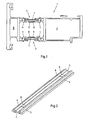
- Das Wesen der Erfindung ist in den
Fig. 1 bis 3 beispielhaft dargestellt; es zeigen: - Fig. 1
- Schalenprofil mit Leichtmetallprofil als Trennung der zwischen der innerer und der äußerer Endleiste verbindenden Stege und einer stabilisierenden Kunststoff-Flachleiste (Schnitt-Ansicht);
- Fig. 2
- Einzelheit Isolatorleiste (perspektivisches Schema, abgeschnitten); und
- Fig. 3
- Einzelheiten unterschiedlich ausgebildeter Stabilisierungsstege (perspektivisches Schema, abgeschnitten).
- Außenschale 2 und Innenschale 3 eines Aluminium-Hohlkammerprofils 1, wie es für Türrahmen oder Fensterrahmen eingesetzt wird, werden durch eine Isolatorleiste 4 fest verbunden. Diese Isolatorleiste 4 wird von den beiden Endleisten 5 und 6 gebildet, zwischen denen sich ein Kunststoff-Flachprofil 7 erstreckt. Damit sind Außenschale 2 und Innenschale 3 auch thermisch voneinander getrennt, so dass ein Wärmefluss von der Innenschale 2 zur Außenschale 3 unterbunden ist. Im störungsfreien Normalbetrieb ist so eine statische einwandfreie Verbindung von Außenschale 2 und Innenschale 3 gegeben, so dass das Aluminium-Hohlkammerprofil 1 den Anforderungen der Statik genügt.
- Um auch in einem durch einen Brand im Inneren gegebenen Störfall die Anforderungen der Statik zumindest für eine gewisse Sicherheitszeitspanne aufrecht erhalten zu können, sind zwischen den beiden Endleisten 5 und 6 der Isolatorleiste 4 des Aluminium-Hohlkammerprofils 1 Stabilisierungsstege 8 vorgesehen. Um im Normalfall einen Wärmeabfluss in Grenzen zu halten, sind zum einen die in Richtung der Längserstreckung der Isolatorleiste 4 gesehene Breite dieser Stabilisierungsstege 8 kleiner als die quer zur Längserstreckung der Isolatorleiste 4 gesehene Breite. Zum anderen sind die Stabilisierungsstege 8 voneinander beabstandet, wobei der Abstand groß gegenüber der Breite der Isolatorleiste 4 ist. So bilden die Stabilisierungsstege 8 zwischen den beiden Endleisten 5 und 6 Haltepunkte für die Isolatorleiste 4 des Aluminium-Hohlkammerprofils 1 und gewährleisten so im Fall, dass das Kunststoff-Flachprofil 7 seine Festigkeit verliert, zumindest für eine gewisse Sicherheitszeitspanne die Statik des von diesem Aluminium-Hohlkammerprofils 1 gebildeten Rahmens.
- Zum weiteren Verbessern des statischen Verhaltens der Stabilisierungsstege 8 sind diese - wie in den
Figuren 3b bis 3d dargestellt - mit zumindest einer hochgestellten Kante 9 versehen. Alternativ können auch zwischen den beiden Endleisten 5 und 6 verlaufende Sicken 10 eingedrückt sein. Durch die dadurch erhöhte Festigkeit kann der Querschnitt der Stabilisierungsstege 8 verringert werden, so dass ein Wärmeabfluss im Normalfall weiter verringert ist.
Claims (7)
- Stranggepresstes oder gezogenes Aluminium-Hohlkammerprofil (1) insbesondere für Türen, bestehend aus einer Innenschale (3) und einer Außenschale (2), zwischen denen zur Unterbrechung des Wärmeflusses als Mittel zur statisch festen Verbindung zumindest eine Isolatorleiste (4) vorgesehen ist,
dadurch gekennzeichnet, dass
die Isolatorleiste (4) als Leichtmetallprofil mit innerer und äußerer Endleiste (5 und 6) und einer Kunststoffprofilleiste als fester Verbinder und thermischer Isolator zwischen diesen beiden ausgebildet ist und dass zwischen beiden Endleisten (5, 6) der Isolatorleiste (4) Stabilisierungsstege (8) vorgesehen sind, die voneinander beabstandet die als Kunststoffflachprofil (7) ausgebildete Kunststoffprofilleiste übergreifend als Haltepunkte im Brandfall für die Endleisten (5, 6) dienen und auch dann die Statik gewährleisten, wenn der Kunststoff infolge Überschreitung einer kritischen Temperaturgrenze seine Festigkeit verliert. - Aluminium-Hohlkammerprofil nach Anspruch 1,
dadurch gekennzeichnet, dass
die Breite der Stabilisierungsstege (8) im Bereich von 1/6 bis 1/3 der Breite der Isolatorleiste (4) liegt. - Aluminium-Hohlkammerprofil nach Anspruch loder 2,
dadurch gekennzeichnet, dass
der Abstand zweier aufeinander folgender Stabilisierungsstege (8) im Bereich der 4-fachen bis 8-fachen Breite der Isolatorleiste (4) liegt. - Aluminium-Hohlkammerprofil nach einem der Ansprüche 1 bis 3,
dadurch gekennzeichnet, dass
die Stabilisierungsstege (8) das statische Verhalten verbessernde Mittel aufweisen. - Aluminium-Hohlkammerprofil nach Anspruch 4,
dadurch gekennzeichnet, dass
die Stabilisierungsstege (8) als deren statisches Verhalten verbesserndes Mittel mit zumindest einer hochgestellten Kante (9) versehen sind. - Aluminium-Hohlkammerprofil nach Anspruch 4,
dadurch gekennzeichnet, dass
die Stabilisierungsstege (8) als deren statisches Verhalten verbesserndes Mittel mit quer zu den Endleisten (5, 6) verlaufende Sicken (10) vorgesehen sind. - Aluminium-Hohlkammerprofil nach einem der Ansprüche 1 bis 6,
dadurch gekennzeichnet, dass
das Kunststoff-Flachprofil (7) als Extrusionsprofil aus einem thermoplastischen Kunststoff aus der Gruppe der Polymerisate oder Polykondensate, vorzugsweise aus Polypropylen oder Polyamid ausgebildet ist.
Applications Claiming Priority (1)
| Application Number | Priority Date | Filing Date | Title |
|---|---|---|---|
| DE201020008621 DE202010008621U1 (de) | 2010-09-24 | 2010-09-24 | Leichtmetallprofil für Fassaden, Fenster, Türen o.dgl. |
Publications (2)
| Publication Number | Publication Date |
|---|---|
| EP2487314A1 EP2487314A1 (de) | 2012-08-15 |
| EP2487314B1 true EP2487314B1 (de) | 2015-08-19 |
Family
ID=44974119
Family Applications (1)
| Application Number | Title | Priority Date | Filing Date |
|---|---|---|---|
| EP11190526.1A Active EP2487314B1 (de) | 2010-09-24 | 2011-11-24 | Leichtmetallprofil für Fassaden, Fenster, Türen oder dergleichen |
Country Status (2)
| Country | Link |
|---|---|
| EP (1) | EP2487314B1 (de) |
| DE (1) | DE202010008621U1 (de) |
Family Cites Families (6)
| Publication number | Priority date | Publication date | Assignee | Title |
|---|---|---|---|---|
| DE9422023U1 (de) * | 1994-12-08 | 1997-08-14 | Schüco International KG, 33609 Bielefeld | Rahmenwerk aus Metallprofilen in Brandschutzausführung für Fenster, Türen, Fassaden oder Glasdächer |
| DE19900793C2 (de) * | 1999-01-12 | 2001-11-22 | Ingbuero Dr Ing Harald Schulz | Brandschutzleiste |
| DE102004008414A1 (de) * | 2004-02-20 | 2005-09-01 | Ingenieurbüro Dr.-Ing. Harald Schulz | Profilrahmenkonstruktion |
| DE202006004607U1 (de) * | 2006-03-21 | 2006-06-01 | SCHÜCO International KG | Rahmenkonstruktion für ein aus Rahmenholmen zusammengesetztes Bauelement |
| EP2136024B1 (de) * | 2008-06-18 | 2011-11-09 | Technoform Bautec Holding GmbH | Verbundprofil für Fenster-, Türen-, oder Fassadenelement mit vorbestimmten Brandschutzeigenschaften und Isoliersteg für ein Verbundprofil mit Brandschutzeigenschaften |
| ATE554257T1 (de) * | 2009-10-28 | 2012-05-15 | Technoform Bautec Holding Gmbh | Verbundprofil für fenster-, türen- oder fassadenelemente mit vorbestimmten brandschutzeigenschaften und verbinder und anschlusselement dafür |
-
2010
- 2010-09-24 DE DE201020008621 patent/DE202010008621U1/de not_active Expired - Lifetime
-
2011
- 2011-11-24 EP EP11190526.1A patent/EP2487314B1/de active Active
Also Published As
| Publication number | Publication date |
|---|---|
| EP2487314A1 (de) | 2012-08-15 |
| DE202010008621U1 (de) | 2011-10-14 |
Similar Documents
| Publication | Publication Date | Title |
|---|---|---|
| EP3140485B1 (de) | Verbundprofil für türen, fenster oder fassadenelemente | |
| EP2527580B1 (de) | Isolationseinsatz für einen aus Profilen gebildeten Rahmen | |
| DE202007016649U1 (de) | Leiterförmiger Isoliersteg für ein Verbundprofil für Fenster-, Türen- und Fassadenelemente und Verbundprofil für Fenster-, Türen- und Fassadenelemente | |
| EP0802300A2 (de) | Rahmenwerk aus Metallprofilen in Brandschutzausführung für Fenster, Türen, Fassaden oder Glasdächer | |
| EP2561169B1 (de) | Abstandhalter | |
| AT510023B1 (de) | Extrusionsdüse | |
| DE202010001301U1 (de) | Wärmegedämmtes Verbundprofil | |
| EP2813657B1 (de) | Rahmenbaugruppe | |
| DE102011117170B4 (de) | Wärmegedämmtes Profil | |
| EP1793073A2 (de) | Gebäudeelement in brandgeschützter Ausführung | |
| EP2472044B1 (de) | Flügel- und/oder Blendrahmen eines Fensters, einer Tür oder dergleichen | |
| EP3184723A1 (de) | Verbundprofil für fenster, türen oder dergleichen | |
| EP2530230B1 (de) | Isoliersteg für Fenster- und Türrahmen | |
| EP2573307A1 (de) | Mehrteiliges Profilrahmensytem für Türen, Tore, Wintergärten und Fenster | |
| AT504806B1 (de) | Zarge für feuerschutztüren, welche aus mehreren parallel verlaufenden teilprofilen gebildet wird | |
| DE19804222C2 (de) | Isoliersteg für Verbundprofile von Fenster- oder Türrahmen | |
| EP2157270B1 (de) | Wärmedämmprofil für Brandschutzkonstruktionen sowie Verbundprofil für Fassaden, Fenster und Türen | |
| EP1182317B1 (de) | Wärmedämmprofil für Brandschutzkonstruktionen | |
| DE20122533U1 (de) | Fensterrahmen oder Fensterflügel | |
| EP2487314A1 (de) | Leichtmetallprofil für Fassaden, Fenster, Türen oder dergleichen | |
| DE102008020988A1 (de) | Wärmeisolierendes Rahmenprofil für die Herstellung von Tür- und Fensterrahmen | |
| DE102013112435A1 (de) | Verbundprofil und Verfahren zum Herstellen eines Verbundprofils | |
| DE202014000509U1 (de) | Wandplatte für eine Trockneranlage | |
| EP0906999A2 (de) | Isoliersteg für Verbundprofile von Fenster- oder Türrahmen | |
| EP3140486B1 (de) | Tür, fenster oder fassadenelement mit einem dichtungssystem |
Legal Events
| Date | Code | Title | Description |
|---|---|---|---|
| PUAI | Public reference made under article 153(3) epc to a published international application that has entered the european phase |
Free format text: ORIGINAL CODE: 0009012 |
|
| AK | Designated contracting states |
Kind code of ref document: A1 Designated state(s): AL AT BE BG CH CY CZ DE DK EE ES FI FR GB GR HR HU IE IS IT LI LT LU LV MC MK MT NL NO PL PT RO RS SE SI SK SM TR |
|
| AX | Request for extension of the european patent |
Extension state: BA ME |
|
| 17P | Request for examination filed |
Effective date: 20130215 |
|
| GRAP | Despatch of communication of intention to grant a patent |
Free format text: ORIGINAL CODE: EPIDOSNIGR1 |
|
| RIC1 | Information provided on ipc code assigned before grant |
Ipc: E06B 3/263 20060101AFI20150204BHEP |
|
| INTG | Intention to grant announced |
Effective date: 20150227 |
|
| GRAS | Grant fee paid |
Free format text: ORIGINAL CODE: EPIDOSNIGR3 |
|
| GRAA | (expected) grant |
Free format text: ORIGINAL CODE: 0009210 |
|
| AK | Designated contracting states |
Kind code of ref document: B1 Designated state(s): AL AT BE BG CH CY CZ DE DK EE ES FI FR GB GR HR HU IE IS IT LI LT LU LV MC MK MT NL NO PL PT RO RS SE SI SK SM TR |
|
| REG | Reference to a national code |
Ref country code: GB Ref legal event code: FG4D Free format text: NOT ENGLISH |
|
| REG | Reference to a national code |
Ref country code: CH Ref legal event code: EP |
|
| REG | Reference to a national code |
Ref country code: IE Ref legal event code: FG4D Free format text: LANGUAGE OF EP DOCUMENT: GERMAN |
|
| REG | Reference to a national code |
Ref country code: AT Ref legal event code: REF Ref document number: 743961 Country of ref document: AT Kind code of ref document: T Effective date: 20150915 |
|
| REG | Reference to a national code |
Ref country code: DE Ref legal event code: R096 Ref document number: 502011007628 Country of ref document: DE |
|
| REG | Reference to a national code |
Ref country code: FR Ref legal event code: PLFP Year of fee payment: 5 |
|
| REG | Reference to a national code |
Ref country code: LT Ref legal event code: MG4D |
|
| REG | Reference to a national code |
Ref country code: NL Ref legal event code: MP Effective date: 20150819 |
|
| PG25 | Lapsed in a contracting state [announced via postgrant information from national office to epo] |
Ref country code: LV Free format text: LAPSE BECAUSE OF FAILURE TO SUBMIT A TRANSLATION OF THE DESCRIPTION OR TO PAY THE FEE WITHIN THE PRESCRIBED TIME-LIMIT Effective date: 20150819 Ref country code: LT Free format text: LAPSE BECAUSE OF FAILURE TO SUBMIT A TRANSLATION OF THE DESCRIPTION OR TO PAY THE FEE WITHIN THE PRESCRIBED TIME-LIMIT Effective date: 20150819 Ref country code: GR Free format text: LAPSE BECAUSE OF FAILURE TO SUBMIT A TRANSLATION OF THE DESCRIPTION OR TO PAY THE FEE WITHIN THE PRESCRIBED TIME-LIMIT Effective date: 20151120 Ref country code: FI Free format text: LAPSE BECAUSE OF FAILURE TO SUBMIT A TRANSLATION OF THE DESCRIPTION OR TO PAY THE FEE WITHIN THE PRESCRIBED TIME-LIMIT Effective date: 20150819 Ref country code: NO Free format text: LAPSE BECAUSE OF FAILURE TO SUBMIT A TRANSLATION OF THE DESCRIPTION OR TO PAY THE FEE WITHIN THE PRESCRIBED TIME-LIMIT Effective date: 20151119 |
|
| PG25 | Lapsed in a contracting state [announced via postgrant information from national office to epo] |
Ref country code: SE Free format text: LAPSE BECAUSE OF FAILURE TO SUBMIT A TRANSLATION OF THE DESCRIPTION OR TO PAY THE FEE WITHIN THE PRESCRIBED TIME-LIMIT Effective date: 20150819 Ref country code: PL Free format text: LAPSE BECAUSE OF FAILURE TO SUBMIT A TRANSLATION OF THE DESCRIPTION OR TO PAY THE FEE WITHIN THE PRESCRIBED TIME-LIMIT Effective date: 20150819 Ref country code: ES Free format text: LAPSE BECAUSE OF FAILURE TO SUBMIT A TRANSLATION OF THE DESCRIPTION OR TO PAY THE FEE WITHIN THE PRESCRIBED TIME-LIMIT Effective date: 20150819 Ref country code: PT Free format text: LAPSE BECAUSE OF FAILURE TO SUBMIT A TRANSLATION OF THE DESCRIPTION OR TO PAY THE FEE WITHIN THE PRESCRIBED TIME-LIMIT Effective date: 20151221 Ref country code: RS Free format text: LAPSE BECAUSE OF FAILURE TO SUBMIT A TRANSLATION OF THE DESCRIPTION OR TO PAY THE FEE WITHIN THE PRESCRIBED TIME-LIMIT Effective date: 20150819 Ref country code: IS Free format text: LAPSE BECAUSE OF FAILURE TO SUBMIT A TRANSLATION OF THE DESCRIPTION OR TO PAY THE FEE WITHIN THE PRESCRIBED TIME-LIMIT Effective date: 20151219 |
|
| PG25 | Lapsed in a contracting state [announced via postgrant information from national office to epo] |
Ref country code: NL Free format text: LAPSE BECAUSE OF FAILURE TO SUBMIT A TRANSLATION OF THE DESCRIPTION OR TO PAY THE FEE WITHIN THE PRESCRIBED TIME-LIMIT Effective date: 20150819 |
|
| PG25 | Lapsed in a contracting state [announced via postgrant information from national office to epo] |
Ref country code: EE Free format text: LAPSE BECAUSE OF FAILURE TO SUBMIT A TRANSLATION OF THE DESCRIPTION OR TO PAY THE FEE WITHIN THE PRESCRIBED TIME-LIMIT Effective date: 20150819 Ref country code: DK Free format text: LAPSE BECAUSE OF FAILURE TO SUBMIT A TRANSLATION OF THE DESCRIPTION OR TO PAY THE FEE WITHIN THE PRESCRIBED TIME-LIMIT Effective date: 20150819 Ref country code: IT Free format text: LAPSE BECAUSE OF FAILURE TO SUBMIT A TRANSLATION OF THE DESCRIPTION OR TO PAY THE FEE WITHIN THE PRESCRIBED TIME-LIMIT Effective date: 20150819 Ref country code: SK Free format text: LAPSE BECAUSE OF FAILURE TO SUBMIT A TRANSLATION OF THE DESCRIPTION OR TO PAY THE FEE WITHIN THE PRESCRIBED TIME-LIMIT Effective date: 20150819 |
|
| REG | Reference to a national code |
Ref country code: DE Ref legal event code: R097 Ref document number: 502011007628 Country of ref document: DE |
|
| PG25 | Lapsed in a contracting state [announced via postgrant information from national office to epo] |
Ref country code: RO Free format text: LAPSE BECAUSE OF FAILURE TO SUBMIT A TRANSLATION OF THE DESCRIPTION OR TO PAY THE FEE WITHIN THE PRESCRIBED TIME-LIMIT Effective date: 20150819 |
|
| PLBE | No opposition filed within time limit |
Free format text: ORIGINAL CODE: 0009261 |
|
| STAA | Information on the status of an ep patent application or granted ep patent |
Free format text: STATUS: NO OPPOSITION FILED WITHIN TIME LIMIT |
|
| PG25 | Lapsed in a contracting state [announced via postgrant information from national office to epo] |
Ref country code: LU Free format text: LAPSE BECAUSE OF FAILURE TO SUBMIT A TRANSLATION OF THE DESCRIPTION OR TO PAY THE FEE WITHIN THE PRESCRIBED TIME-LIMIT Effective date: 20151124 Ref country code: MC Free format text: LAPSE BECAUSE OF FAILURE TO SUBMIT A TRANSLATION OF THE DESCRIPTION OR TO PAY THE FEE WITHIN THE PRESCRIBED TIME-LIMIT Effective date: 20150819 |
|
| REG | Reference to a national code |
Ref country code: CH Ref legal event code: PL |
|
| 26N | No opposition filed |
Effective date: 20160520 |
|
| GBPC | Gb: european patent ceased through non-payment of renewal fee |
Effective date: 20151124 |
|
| PG25 | Lapsed in a contracting state [announced via postgrant information from national office to epo] |
Ref country code: CH Free format text: LAPSE BECAUSE OF NON-PAYMENT OF DUE FEES Effective date: 20151130 Ref country code: LI Free format text: LAPSE BECAUSE OF NON-PAYMENT OF DUE FEES Effective date: 20151130 |
|
| REG | Reference to a national code |
Ref country code: IE Ref legal event code: MM4A |
|
| PG25 | Lapsed in a contracting state [announced via postgrant information from national office to epo] |
Ref country code: SI Free format text: LAPSE BECAUSE OF FAILURE TO SUBMIT A TRANSLATION OF THE DESCRIPTION OR TO PAY THE FEE WITHIN THE PRESCRIBED TIME-LIMIT Effective date: 20150819 |
|
| PG25 | Lapsed in a contracting state [announced via postgrant information from national office to epo] |
Ref country code: GB Free format text: LAPSE BECAUSE OF NON-PAYMENT OF DUE FEES Effective date: 20151124 Ref country code: IE Free format text: LAPSE BECAUSE OF NON-PAYMENT OF DUE FEES Effective date: 20151124 |
|
| REG | Reference to a national code |
Ref country code: FR Ref legal event code: PLFP Year of fee payment: 6 |
|
| PG25 | Lapsed in a contracting state [announced via postgrant information from national office to epo] |
Ref country code: SM Free format text: LAPSE BECAUSE OF FAILURE TO SUBMIT A TRANSLATION OF THE DESCRIPTION OR TO PAY THE FEE WITHIN THE PRESCRIBED TIME-LIMIT Effective date: 20150819 Ref country code: BG Free format text: LAPSE BECAUSE OF FAILURE TO SUBMIT A TRANSLATION OF THE DESCRIPTION OR TO PAY THE FEE WITHIN THE PRESCRIBED TIME-LIMIT Effective date: 20150819 Ref country code: HU Free format text: LAPSE BECAUSE OF FAILURE TO SUBMIT A TRANSLATION OF THE DESCRIPTION OR TO PAY THE FEE WITHIN THE PRESCRIBED TIME-LIMIT; INVALID AB INITIO Effective date: 20111124 |
|
| PG25 | Lapsed in a contracting state [announced via postgrant information from national office to epo] |
Ref country code: CY Free format text: LAPSE BECAUSE OF FAILURE TO SUBMIT A TRANSLATION OF THE DESCRIPTION OR TO PAY THE FEE WITHIN THE PRESCRIBED TIME-LIMIT Effective date: 20150819 |
|
| PG25 | Lapsed in a contracting state [announced via postgrant information from national office to epo] |
Ref country code: HR Free format text: LAPSE BECAUSE OF FAILURE TO SUBMIT A TRANSLATION OF THE DESCRIPTION OR TO PAY THE FEE WITHIN THE PRESCRIBED TIME-LIMIT Effective date: 20150819 Ref country code: BE Free format text: LAPSE BECAUSE OF NON-PAYMENT OF DUE FEES Effective date: 20151130 |
|
| PG25 | Lapsed in a contracting state [announced via postgrant information from national office to epo] |
Ref country code: MT Free format text: LAPSE BECAUSE OF FAILURE TO SUBMIT A TRANSLATION OF THE DESCRIPTION OR TO PAY THE FEE WITHIN THE PRESCRIBED TIME-LIMIT Effective date: 20150819 Ref country code: TR Free format text: LAPSE BECAUSE OF FAILURE TO SUBMIT A TRANSLATION OF THE DESCRIPTION OR TO PAY THE FEE WITHIN THE PRESCRIBED TIME-LIMIT Effective date: 20150819 |
|
| REG | Reference to a national code |
Ref country code: FR Ref legal event code: PLFP Year of fee payment: 7 |
|
| PG25 | Lapsed in a contracting state [announced via postgrant information from national office to epo] |
Ref country code: MK Free format text: LAPSE BECAUSE OF FAILURE TO SUBMIT A TRANSLATION OF THE DESCRIPTION OR TO PAY THE FEE WITHIN THE PRESCRIBED TIME-LIMIT Effective date: 20150819 |
|
| PG25 | Lapsed in a contracting state [announced via postgrant information from national office to epo] |
Ref country code: AL Free format text: LAPSE BECAUSE OF FAILURE TO SUBMIT A TRANSLATION OF THE DESCRIPTION OR TO PAY THE FEE WITHIN THE PRESCRIBED TIME-LIMIT Effective date: 20150819 |
|
| P01 | Opt-out of the competence of the unified patent court (upc) registered |
Effective date: 20230514 |
|
| PGFP | Annual fee paid to national office [announced via postgrant information from national office to epo] |
Ref country code: DE Payment date: 20251120 Year of fee payment: 15 |
|
| PGFP | Annual fee paid to national office [announced via postgrant information from national office to epo] |
Ref country code: AT Payment date: 20251124 Year of fee payment: 15 |
|
| PGFP | Annual fee paid to national office [announced via postgrant information from national office to epo] |
Ref country code: FR Payment date: 20251120 Year of fee payment: 15 |
|
| PGFP | Annual fee paid to national office [announced via postgrant information from national office to epo] |
Ref country code: CZ Payment date: 20251014 Year of fee payment: 15 |