EP2486992B1 - Dehn- und formmaschine mit mehreren klemmen - Google Patents
Dehn- und formmaschine mit mehreren klemmen Download PDFInfo
- Publication number
- EP2486992B1 EP2486992B1 EP10821593.0A EP10821593A EP2486992B1 EP 2486992 B1 EP2486992 B1 EP 2486992B1 EP 10821593 A EP10821593 A EP 10821593A EP 2486992 B1 EP2486992 B1 EP 2486992B1
- Authority
- EP
- European Patent Office
- Prior art keywords
- ball
- clamping
- stretching
- mechanisms
- forming machine
- Prior art date
- Legal status (The legal status is an assumption and is not a legal conclusion. Google has not performed a legal analysis and makes no representation as to the accuracy of the status listed.)
- Not-in-force
Links
Images




Classifications
-
- B—PERFORMING OPERATIONS; TRANSPORTING
- B21—MECHANICAL METAL-WORKING WITHOUT ESSENTIALLY REMOVING MATERIAL; PUNCHING METAL
- B21D—WORKING OR PROCESSING OF SHEET METAL OR METAL TUBES, RODS OR PROFILES WITHOUT ESSENTIALLY REMOVING MATERIAL; PUNCHING METAL
- B21D11/00—Bending not restricted to forms of material mentioned in only one of groups B21D5/00, B21D7/00, B21D9/00; Bending not provided for in groups B21D5/00 - B21D9/00; Twisting
- B21D11/02—Bending by stretching or pulling over a die
-
- B—PERFORMING OPERATIONS; TRANSPORTING
- B21—MECHANICAL METAL-WORKING WITHOUT ESSENTIALLY REMOVING MATERIAL; PUNCHING METAL
- B21D—WORKING OR PROCESSING OF SHEET METAL OR METAL TUBES, RODS OR PROFILES WITHOUT ESSENTIALLY REMOVING MATERIAL; PUNCHING METAL
- B21D25/00—Working sheet metal of limited length by stretching, e.g. for straightening
- B21D25/04—Clamping arrangements
Definitions
- the invention relates to a multi-clamp type stretch forming machine according to the preamble of claim 1 (see for example CN-A-101214505 ) which is used in the mechanical engineering field for plastic processing of a sheet type workpiece to form a curved surface.
- the stretching action is generally provided by means of only one or two hydraulic cylinders, and the sheet material of the workpiece is substantially integrally displaced in a transverse direction at the edge clamped by the clamps.
- the distribution of stretch stress and stretch strain in the transverse direction of the sheet material becomes obviously not uniform, which results in processing defects such as departure from mold, cracking and wrinkling.
- precision requirements to the forming machines are very high, and the control systems of them have generally complex designs, thus the forming machines are very expensive.
- the blank material for stretch forming has generally a relatively large non-processed margin area, which results in low material usage.
- the machine aims at facilitating even tensile stress and tensile strain distribution of stretch-forming parts, realizing stretch-forming of curved parts with large curvature, improving stretch-forming quality and material utilization ratio and reducing the manufacturing cost of stretch-forming devices.
- the machine mainly comprises a rack, a row of multiple material-pulling mechanisms and a row of multiple material-stretching mechanisms, which are arranged at the left and right sides of the rack respectively.
- the material-pulling mechanism is formed by a mutual hinge joint of three hydraulic cylinders, wherein, one of the three hydraulic cylinders is horizontally arranged, one vertically is arranged and one is obliquely arranged.
- the material-stretching mechanism is mainly composed of a support, a material-stretching plate and a small-stroke single-acting hydraulic cylinder.
- An object of the invention is to overcome the above mentioned defects by providing a multi-clamp type stretch forming machine having high flexibility.
- the machine by using Pascal law in multi-cylinder hydraulic systems, process hardening characteristics of materials and law of minimum resistance, flexible control of multi-clamps is achieved in a simple way.
- the workpiece is more liable to be affixed to its forming mold, and the workpiece may have significantly increased material usage and stretch forming quality.
- the multi-clamp type stretch forming machine of the invention can provide more uniform distribution of stretch stress and stretch strain, so that workpiece with curved surfaces can be stretch formed more uniformly. Meanwhile, manufacturing cost of the stretch forming machines can be lowered down.
- the invention provides a multi-clamp type stretch forming machine, comprising clamping mechanisms, stretching mechanisms and a machine frame, each clamping mechanism comprising a clamping frame, a clamper and a hydraulic clamping cylinder, and a row of multiple clamping mechanisms aligned on each of opposite sides of the machine frame, characterized by the clamping frame of each clamping mechanism being provided with two connecting holes, each connecting hole being coupled with one or more stretching mechanisms by means of a universal push-pull mechanism, wherein said two connecting holes comprise a rear connecting hole and a lower connecting hole, the lower connecting hole being coupled with a vertically disposed stretching mechanism by means of a universal push-pull mechanism, and the rear connecting hole being couple, by means of another universal push-pull mechanism, with a horizontally disposed stretching mechanism, or simultaneously with a set of stretching mechanism which comprise any combination of a horizontally disposed stretching mechanism, an obliquely disposed stretching mechanism and a vertically disposed stretching mechanism.
- each stretching mechanism comprises a hydraulic stretching cylinder, and a row of hydraulic stretching cylinders aligned in the same direction are controlled by means of one or more solenoid type reversing valves.
- each universal push-pull mechanism mainly comprises a ball-headed linkage, or mainly comprises a pivot shaft, or mainly comprises a combination of a ball-headed linkage, a pivot shaft and a link; one end of the ball-headed linkage forms a ball-shaped head, the ball-shaped head being mounted in the clamping frame or in a stretching link, directly or by means of a bearing shoe having a half-ball-shaped recess which is fit with ball-shaped surface of a retention portion of the ball-shaped head; and the opposite end of the ball-headed linkage is coupled with a corresponding link by means of a screw type mechanism or a pivot shaft.
- the ball-shaped head has a half-ball shape or a complete-ball shape; in the condition that the ball-shaped head has a half-ball shape, an elastic pad, such as a polyurethane pad, is provided at the ball-shaped head; and in the condition that the ball-shaped head has a complete-ball shape, a thrust bearing shoe having a half ball-shaped recess is provided at the ball-shaped head.
- an elastic pad such as a polyurethane pad
- the ball-headed linkage comprises two ball-headed linkages which are coupled with each other symmetrically by means of a bar-like link, and thus a universal push-pull mechanism having dual ball-shaped heads is formed.
- the length of the universal push-pull mechanism is adjustable by means of a length-adjustable bar-like link.
- the pivot shaft is a solid pivot shaft or a hollow pivot shaft; and in the condition of a hollow pivot shaft, one or more steel wires or flexible steel shafts are inserted through a row of hollow pivot shafts.
- pivot shafts are substituted by one or more steel wires or flexible steel shafts inserted through the clamping mechanisms.
- each clamping mechanism in a row of multiple clamping mechanisms disposed on either side of the machine frame comprises a pair of clampers, a gap is formed between neighboring clampers, each clamper comprises a clamping surface, a front edge and two front corners of which are rounded with relatively large radii, and right and left edges of the clamping surface, which are adjacent to other clampers, are also be rounded.
- the clamping surface of the clamper is a horizontal surface; or the clamping surface has a back end slightly higher than its front end; or the clamping surface has a back end which is a horizontal surface and is slightly higher than the front end of the clamping surface; or the clamping surface has a middle portion which is slightly higher than its left and right ends which are adjacent to other clampers and tapered gradually.
- the clamper has a rectangular shape, a trapezoidal shape, or a six-sided shape which is composed of a rectangle and a trapezoid; and the length of the front side of the clamping surface is equal to or less than the length of the back side of the clamping surface.
- each clamper is a biting clamper which has a clamping surface formed with many biting protrusions or a sliding-through clamper which has a clamping surface formed with several drawing ribs; and the biting clampers and the sliding-through clamper can be used in a mixed manner in a row of multiple clamping mechanisms.
- the distance between the clamping mechanisms and the stretching mechanisms on the left side of the machine frame and the clamping mechanisms and the stretching mechanisms on the right side of the machine frame is adjustable; and/or a forming mold to be used with the stretch forming machine comprises a solid mold or a multi-point adjustable digitalized mold, the forming mold having a mold base which is movable upwards; and/or a pushing-down mechanism is mounted to an upper portion of the stretch forming machine.
- the Pascal law in a multi-cylinder hydraulic system, process hardening characteristics of materials and law of minimum resistance are used in the invention, so that, under the same level of hydraulic force of a row of hydraulic cylinders, a plurality of clamping mechanisms can move and rotate to follow the curvature of a molding surface.
- the load applying pattern on the workpiece is optimized, and the stretch stress and the stretch strain in the workpiece are distributed more uniformly.
- the mold affixing ability of the workpiece is increased, the non-processed margin area of a stretch formed piece is decreased, and the material usage and the forming quality are increased.
- the multi-clamp type stretch forming machine provides flexible control to a plurality of clampers by using a simple and cost efficient hydraulic system, so that the workpiece forming effect is improved with respect to traditional stretch forming machines.
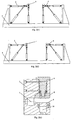
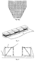
- Figure 1 includes a set of schematic views of a multi-clamp type stretch forming machine in which each clamping frame has a single connecting hole, wherein Figure 1(a) is an isometric view, Figure 1(b) is a front view, and Figure 1(c) is a schematic enlarged sectional view of a clamping mechanism shown in Figures 1(a) and 1(b) .
- the multi-clamp type stretch forming machine mainly comprises clamping mechanisms 1, stretching mechanisms 2 and a machine frame 3.
- Each stretching mechanism 2 mainly comprises a hydraulic stretching cylinder and coupling members.
- the stretching mechanism may be embodied as other mechanisms that can generate stretching force and displacement, such as any one of screw type drive mechanisms, rack and pinion mechanisms, cam and linkage mechanisms and the like.
- a row of ten clamping mechanisms 1 are disposed on each of opposite sides of the machine frame 3. It is noted that ten clamping mechanisms 1 are provided here only for illustrative purpose, and any other number of clamping mechanisms 1 can be provided in accordance with various stretch forming conditions.
- each clamping mechanism 1 comprises a clamping frame 7, clampers 8 and 9, and a hydraulic clamping cylinder 6.
- the hydraulic clamping cylinder 6 of the clamping mechanism 1 forms an integral structure with the clamping frame 7.
- the hydraulic clamping cylinder 6 of the clamping mechanism 1 and the clamping frame 7 may alternatively be formed as individual parts that are then combined together.
- the hydraulic clamping cylinder 6 of the clamping mechanism 1 is a double-acting hydraulic cylinder with a short stroke.
- the clamper 8 is fixedly mounted to a piston of the hydraulic clamping cylinder 6 by screws
- the clamper 9 is fixedly mounted to the clamping frame 7 by screws.
- a hydraulic fluid is fed into the hydraulic clamping cylinder via an upper port in the clamping frame 7 and is discharged out from the hydraulic clamping cylinder via a lower port in the clamping frame 7, so that the hydraulic clamping cylinder 6 of the clamping mechanism 1 drives the clamper 8, which is coupled with the piston, to move downwards and clamps the sheet material tightly with the clamper 9 which is coupled with the clamping frame 7.
- the hydraulic fluid is fed via the lower port in the clamping frame 7 and discharged from the upper port, so that the hydraulic clamping cylinder 6 is controlled to drive the clamper 8, which is coupled with the piston, to move upwards away from the clamper 9 which is coupled with the clamping frame 7, and thus the sheet material is released.
- the clamping frame 7 comprises a rear connecting hole 5.
- the clamping frame is coupled with three stretching mechanisms 2 simultaneously at the rear connecting hole 5 by means of a universal push-pull mechanism 4 which comprises mainly a ball-headed linkage and two pivot shafts, wherein the first stretching mechanism is disposed in a horizontal orientation, the second stretching mechanism is disposed in a vertical orientation, and the third stretching mechanism is disposed in an oblique orientation.
- the clamping frame may be coupled simultaneously with two stretching mechanisms 2 at the rear connecting hole 5 by means of a universal push-pull mechanism 4, wherein the first stretching mechanism is disposed in a horizontal orientation, while the second stretching mechanism is disposed in a vertical orientation or in an oblique orientation.
- FIGS 1(d) and 1(e) show schematic views of the universal push-pull mechanism 4, which comprises mainly a ball-headed linkage and two pivot shafts, as used in the embodiment shown in Figures 1(a) and 1(b) .
- the universal push-pull mechanism 4 comprises hydraulic cylinder type links 10, a hollow pivot shaft 11, a stretching link 12, a ball-headed linkage 13, a clamping linkage 14 and a solid pivot shaft 15.
- the stretching link 12 is coupled with three hydraulic cylinder type links 10 by means of the hollow pivot shaft 11.
- the ball-headed linkage 13 is coupled at one end with the stretching link 12 by means of a ball-shaped head, and coupled at the opposite end with the clamping linkage 14 by means of a screw type mechanism.
- the clamping linkage 14 is coupled with the clamping frame 7 of the clamping mechanism 1 by means of the solid pivot shaft 15.
- the clamping mechanism 1 is able to swing around the axis of the solid pivot shaft 15, and able to rotate around the axis of the ball-headed linkage 13 by means of the ball-headed linkage 13.
- the clamping mechanism 1 will swing and rotate to follow the shape of the curved surface of a stretch forming mold.
- the clamping frame is coupled at its rear connecting hole with one or more corresponding stretching mechanisms by means of a universal push-pull mechanism comprising mainly a ball-headed linkage and two pivot shafts.
- a universal push-pull mechanism comprising mainly a ball-headed linkage and two pivot shafts.
- the clamping frame may be coupled at its rear connecting hole with one or more corresponding stretching mechanisms by means of a universal push-pull mechanism comprising a ball-headed linkage or a pivot shaft.
- the number of the ball-headed linkage(s) and the number of the pivot shaft(s) used in the universal push-pull mechanism and the combination manner of them may be varied.
- the loading directions of the hydraulic stretching cylinders and the angles therebetween can be changed by changing the hydraulic forces and the strokes of the hydraulic stretching cylinders of the stretching mechanism 1, so that the position and the stretching direction of the clamping mechanism 1 are changed.
- the position and the stretching direction of each clamping mechanism 1 are controlled by controlling the level of the hydraulic force and the stroke of the hydraulic stretching cylinder of the horizontal, vertical or oblique stretching mechanism, so that optimal stretching position and angle are established in the sheet material.
- the stretching mechanism 2 and the clamping mechanism 1 are coupled by means of the universal push-pull mechanism 4, so that the clamping mechanism 1 may swing and rotate to follow the deforming tendency of the sheet material.
- the stretch forming machine has advantageously high flexibility.
- a row of hydraulic cylinders disposed in the same orientation can be controlled by a single solenoid type reversing valve, by means of which, Pascal law in a multi-cylinder hydraulic system, process hardening characteristics of materials and law of minimum resistance are used advantageously, so that, under the action of a row of hydraulic cylinders having the same hydraulic force level, the clamping mechanisms 1 will move and rotate to follow the profile of the curved surface of the forming mold. As a result, the workpiece is likely to be affixed to the forming mold, and thus the material usage and the stretch forming quality of the workpiece can be increased.
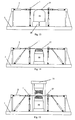
- Figure 2 includes a set of schematic views of a multi-clamp type stretch forming machine in which each clamping frame has two connecting holes, wherein Figure 2(a) is a front view showing a rear connecting hole 5 and a lower connecting hole 16 of the clamping frame 7, each connecting hole being coupled with one or more corresponding stretching mechanisms 2 by means of a universal push-pull mechanism 4 comprising mainly a ball-headed linkage and two pivot shafts.
- the exemplary embodiment shown in Figure 2(a) has a basic structure and operation procedure similar to that of the exemplary embodiment shown in Figures 1(a), 1(b) and 1(c) . Only the differences between them will be described for simplicity.
- each clamping frame 7 is provided with a rear connecting hole 5 and a lower connecting hole 16.
- the clamping frame 7 is coupled, at the rear connecting hole 5, simultaneously with two stretching mechanisms 2 respectively by means of a universal push-pull mechanism 4 comprising mainly a ball-headed linkage and two pivot shafts, wherein the first stretching mechanism is disposed in a horizontal orientation, and the second stretching mechanism is disposed in an oblique orientation.
- the clamping frame 7 is also coupled, at the lower connecting hole 16, with a stretching mechanism 2 disposed in a vertical direction by means of a universal push-pull mechanism 4 comprising mainly a ball-headed linkage and two pivot shafts.
- the stretching mechanisms coupled with the clamping frame at the rear connecting hole 5 are adapted to apply a stretching force and to control the stretching direction
- the stretching mechanism coupled with the clamping frame at the lower connecting hole 16 is adapted to finely adjust the stretching direction.
- the stretching force and the stretching direction of the clamping mechanism 1 can be adjusted by adjusting the hydraulic force levels of the hydraulic stretching cylinders of stretching mechanisms disposed in different directions.
- the universal push-pull mechanism for coupling the clamping frame 7 and the stretching mechanism 2 may be in the form of either a universal push-pull mechanism 4 composed of a ball-headed linkage or a universal push-pull mechanism 4 composed of a pivot shaft, only if the same stretching effect can be obtained.
- the number of the ball-headed linkage(s) and the number of the pivot shaft(s) used in the universal push-pull mechanism and the combination manner of them may be varied.
- the clamping frame 7 is coupled at the lower connecting hole 16 with a stretching mechanism 2, which is disposed in a vertical direction, by means of a universal push-pull mechanism 4 comprising a pivot shaft. Further, the clamping frame 7 is coupled at the rear connecting hole 5 with two stretching mechanisms 2 by means of a universal push-pull mechanism 4 which comprises mainly a ball-headed linkage and two pivot shafts, wherein the first stretching mechanism is disposed in a horizontal orientation, and the second stretching mechanism is disposed in an oblique orientation.
- the basic structure and the operation procedure of the clamping mechanism 1 shown in Figure 2(c) are similar to that of the exemplary embodiment shown in Figure 2(b) .
- the degree of freedom of each clamping mechanism is significantly increased because the clamping mechanism is able to rotate and swing in a free way around the ball-shaped head of the ball-headed linkage of the universal push-pull mechanism 4, so that a row of multiple clamping mechanisms 1 can be aligned in a straight or curve line.
- Flexible control of a plurality of clamping mechanisms can also be achieved, so that the workpiece is more liable to be affixed to the forming mold in a stretch forming process, the material usage of the workpiece is significantly increased, and better workpiece forming effect can be obtained.
- the universal push-pull mechanisms 4 used in the schematic view of Figure 2 are described here only for illustrative purpose, the universal push-pull mechanism 4 comprising mainly a ball-headed linkage and two pivot shafts and the universal push-pull mechanism 4 comprising mainly a ball-headed linkage or a pivot shaft may alternatively be constructed in other forms different from that described here, only if the purpose of increasing the degree of freedom of the clamping mechanism can be increased.
- the clamping frame 7 is coupled at its rear connecting hole 5 and lower connecting hole 16 with stretching mechanisms by means of universal push-pull mechanisms each comprising mainly a ball-headed linkage and a pivot shaft.
- FIG 2(e) is an enlarged sectional view of a clamping mechanism shown in Figure 2(d) .
- the clamping frame 7 is coupled at the rear connecting hole 5 with two stretching mechanisms 2 by means of a universal push-pull mechanism 4 which comprises mainly a ball-headed linkage and a pivot shaft, wherein the first stretching mechanism is disposed in a horizontal orientation, and the second stretching mechanism is disposed in an oblique orientation.
- the clamping frame is also coupled at the lower connecting hole 16 with a stretching mechanism, which is disposed in a vertical direction, by means of a universal push-pull mechanism 4 which comprises mainly a ball-headed linkage and a pivot shaft.
- the clamping frame can be coupled at the rear connecting hole 5 with a stretching mechanism, which disposed in a horizontal direction, by means of a universal push-pull mechanism, or coupled simultaneously with any combination of stretching mechanisms disposed in a horizontal direction, in an oblique orientation and in a vertical direction, only if the same stretching effect can be obtained.
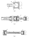
- Figures 3 and 4 show, only for illustrative purpose, illustrative optional embodiments of clamping mechanisms coupled by means of universal push-pull mechanisms each mainly comprises a ball-headed linkage, a link and the like.
- Figure 3(a) is a sectional view of a ball-headed linkage 13, having a half ball-shaped head at one end, mounted directly in a connecting hole of the clamping frame 7.
- a ring-like polyurethane pad 18 is provided at a half-ball-shaped end of the ball-headed linkage 13. It is practical to adjust the level of the elastic returning force of the ring-like polyurethane pad by varying the inner and outer diameters and the thickness of the ring-like polyurethane pad.
- the ring-like polyurethane pad 18 having a lower elastic returning force can be substituted by a circular polyurethane pad 20 having a higher elastic returning force according to real need.
- the opposite end of the ball-headed linkage 13 or 22 (with reference to Figure 4 ), which does not have a ball-shaped head, can be coupled with the stretching mechanism 2 by means of a screw type mechanisms and a bar-like link 17.
- a screw type mechanisms and a bar-like link 17.
- other coupling manners such as snap lock can also be used.
- Figure 3(b) is a sectional view of a ball-headed linkage 13, having a half-ball-shaped head at one end, mounted in a connecting hole of the clamping frame 7 by means of a bearing shoe 19 having a half-ball-shaped recess.
- the material for forming the bearing shoe 19 may be a bearing material such as copper or Nylon.
- a circular polyurethane pad 20 can be provided at a half-ball-shaped end. It is practical to adjust the level of the elastic returning force of the circular polyurethane pad 20 by adjusting the diameter and the thickness of it. Alternatively, the circular polyurethane pad 20 having a higher elastic returning force can be substituted by a ring-like polyurethane pad 18 having a lower elastic returning force according to real need.
- Figure 3(c) is a sectional view of a ball-headed linkage 13, having a half-ball-shaped head at one end, mounted in a connecting hole of the clamping frame 7 by means of a bearing shoe 19 having a half ball-shaped recess and a head retaining ring 21.
- a lubricant may be applied between an inner retention portion of the half-ball-shaped head and the bearing shoe 19 for lubrication.
- Figure 4 is a sectional view of a ball-headed linkage 22, having a complete-ball-shaped head at one end, mounted in a connecting hole of the clamping frame 7.
- An inner retention portion of the ball-shaped head is equipped with a bearing shoe 19 having a half-ball-shaped recess, and an outer free end of the complete-ball-shaped head is equipped with a thrust bearing shoe 23 having another half-ball-shaped recess.
- a lubricant may be applied between the ball-shaped head and the bearing shoe for lubrication.
- Figure 5 is a sectional view showing an embodiment in which two ball-headed linkages 13, each having a half-ball-shaped head at one end, are adopted.
- the two half-ball-shaped heads each has an inner retention portion equipped with a bearing shoe 19 which defines a half-ball-shaped recess, and an outer free end equipped with a circular polyurethane pad 20.
- a lubricant may be applied between an inner retention portion of the half-hall-shaped head and the bearing shoe 19 for lubrication.
- the two ball-headed linkages each has an opposite end which does not have a ball-shaped head and is coupled with a common bar-like link 17 by means of a screw type mechanism.
- the ball-headed linkage on the right side of the bar-like link 17 is coupled with the clamping frame 7, and the ball-headed linkage on the left side is coupled with two stretching mechanisms 2.
- Figure 6 is a sectional view showing an embodiment in which two ball-headed linkages 13, each having a half-ball-shaped head, are adopted in combination with a length-adjustable bar-like link24.
- the length-adjustable bar-like link 24 is coupled between the two ball-headed linkage 13 by means of screw type mechanisms.
- the length of a universal push-pull mechanism which comprises mainly two ball-headed linkages or the like, can be adjusted by means of the length-adjustable bar-like link, which results in smaller non-processed margin area of workpiece, and various production requirements of multi-type workpiece can be met.
- the length-adjustable bar-like link 24 can be coupled with the ball-headed linkage 13 by any suitable connection manners, such as snap lock type and bolt type connections.
- connection manners such as snap lock type and bolt type connections.
- the length-adjustable bar-like link 24 can be coupled between the ball-headed linkage 13 and the clamping linkage 14 by means of a screw type mechanism or other mechanisms.
- linkages such as the ball-headed linkage 13 and the clamping linkage 14 can also have adjustable lengths to account for the above condition.
- a ring-like or circular polyurethane pad is adopted in the exemplary embodiments shown in Figures 3 to 6 .
- the purpose of adopting a polyurethane pad is that, after the stretch forming, the ball-headed linkage can automatically return to its original position under the elastic returning force provided by the polyurethane pad.
- the polyurethane pad can be substituted by an elastic pad made of any other elastic material, or substituted by a spring.
- Figure 7 includes a set of sectional views showing clamping frames and stretching mechanisms coupled by means of universal push-pull mechanisms which comprise different combinations of pivot shafts, a steel wire, a flexible steel shaft or similar elements.
- Figure 7(a) is a sectional view showing an embodiment in which stretching links and hydraulic cylinder type links are coupled by means of a plurality of hollow pivot shafts through which a steel wire or flexible steel shaft is inserted.
- a first end of each stretching link 12 is coupled with a corresponding clamping frame 7 by means of two ball-headed linkages 13 each having a half-ball-shaped head at one end, and a second end of the stretching link 12 is coupled with two hydraulic cylinder type links 10 by means of a hollow pivot shaft 11 through which a common steel wire or flexible steel shaft 25 is inserted.
- Opposite ends of the steel wire or flexible steel shaft 25 are each fixed with a retainer 26 by a screw, for restricting the axial displacement of the common steel wire or flexible steel shaft.
- the universal push-pull mechanisms each comprising mainly of two ball-headed linkages and a pivot shaft, and the clamping mechanisms can be displaced in a substantially synchronized manner.
- the steel wire or flexible steel shaft has an outer diameter which is smaller than the inner diameter of the hollow pivot shaft, so that a row of universal push-pull mechanisms, each comprising mainly two ball-headed linkages and a pivot shaft, can be aligned along a curve line.
- Figure 7(b) is a sectional view showing an embodiment in which stretching links and hydraulic cylinder type links are coupled by means of a plurality of solid pivot shafts, and clamping frames and clamping linkages are coupled by means of a plurality of hollow pivot shafts through which a steel wire or flexible steel shaft is inserted.
- Each clamping linkage 14 is coupled with the clamping frame 7 of a corresponding clamping mechanism by means of a hollow pivot shaft 11, and each stretching link 12 is coupled with three hydraulic cylinder type links 10 by means of a solid pivot shaft 15.
- a common steel wire or flexible steel shaft 25 is inserted through the hollow pivot shafts 11, and opposite ends of the steel wire or flexible steel shaft 25 are each fixed with a retainer 26 by a screw, for restricting the axial displacement of the common steel wire or flexible steel shaft.
- Figure 7(c) is a sectional view showing an embodiment in which stretching links and hydraulic cylinder type links are coupled and clamping frames and clamping linkages are coupled respectively by means of a plurality of hollow pivot shaft through which a steel wire or flexible steel shaft is inserted.
- Each clamping linkage 14 is coupled with the clamping frame 7 of a corresponding clamping mechanism by means of a hollow pivot shaft 11, and each stretching link 12 is coupled with three hydraulic cylinder type links 10 by means of another hollow pivot shaft 11.
- the universal push-pull mechanism may be formed directly by several steel wire or flexible steel shafts 25.
- Figure 7(d) is a sectional view showing an embodiment in which stretching links and hydraulic cylinder type links are coupled and clamping frames and clamping linkages are coupled respectively by means of a steel wire or flexible steel shaft 25 directly.
- Each clamping linkage 14 is coupled with the clamping frame 7 of a corresponding clamping mechanism by means of a common steel wire or flexible steel shaft 25, and each stretching link 12 is coupled with three hydraulic cylinder type links 10 by means of another common steel wire or flexible steel shaft 25.
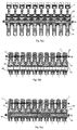
- Figure 8 is a schematic view showing an embodiment in which multiple pairs of biting clampers are adopted.
- right and left sides of the stretch forming machine are each provided with a row of five pairs of biting clampers.
- the clamper comprises a clamping surface, a front edge and two front corners of which are rounded with relatively large radii. Right and left edges of the clamping surface, which are adjacent to neighboring clampers, are also be rounded with a certain radius.
- the clamping surface is of biting type by providing many biting protrusions, so that the sheet material can be clamped tightly between each pair of clampers. Thus, during the stretch forming process, the sheet material is not allowed to move in the biting areas of the clampers.
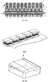
- Figure 9 includes a set of schematic views of clampers with slanted clamping surfaces, wherein Figure 9(a) is a schematic view of a clamper having a height gradually reduced from its back end to its front end; and Figure 9(b) is a schematic view of a clamper having a horizontal segment and a tapered segment from its back end to its front end.
- the clamping surface of the clamper shown in Figure 9(a) and Figure 9(b) is higher in its middle portion and is tapered gradually towards its left and right sides.
- the taper angle ⁇ of the clamper from its back end to its front end is preferably smaller than the taper angle P from the middle portion of the clamping surface to the right and left sides.
- the sheet material In the thicker areas of the clampers, the sheet material is clamped by the clamps tightly by maximum clamping forces, and thus no displacement of the sheet material is allowed. On the other hand, in the tapered areas of the clampers, the clamping forces are decreased gradually, so that a certain degree of displacement and expansion of the sheet material are allowed.
- Figure 10 includes a set of schematic views of clampers of different shapes, wherein Figure 10(a) is a schematic view of a rectangular clamper; Figure 10(b) is a schematic view of a trapezoidal clamper; and Figure 10(c) is a schematic view of a six-sided clamper having a profile formed by combination of a rectangle and a trapezoid.
- the clamping surface is formed with a front side length which is equal to or less than the back side length of the clamping surface, which helps the displacement and expansion of the sheet material with larger gradients occur in the area near the clamping surface, so that the stretch forming of a workpiece with a large transverse curvature or having transverse wave shape can be performed, and various production requirements of multi-type workpiece can be met.
- Figure 11 is a schematic view showing an embodiment in which biting clampers are used in combination with sliding-through clampers.
- the biting clampers which have many biting protrusions on their clamping surfaces and the sliding-through clampers which have several drawing ribs on their clamping surfaces can be alternately disposed one by one or set by set, so that displacement and expansion with larger gradients can occur in the sheet material.
- the clamping mechanisms can be aligned along a curve line or a wave line to follow the profile of the forming mold, and flexible control of a plurality of clampers of a stretch forming machine can be achieved.
- Figure 12 is a schematic view of a multi-clamp type stretch forming machine in which the distance between right side clamping mechanism 1 and stretching mechanism 2 and left side clamping mechanism 1 and stretching mechanism 2 is adjustable.
- the distance between a plurality of clamping mechanism 1 and stretching mechanisms 2 on the left side of the machine frame and a plurality of clamping mechanism 1 and stretching mechanisms 2 on the right side of the machine frame can be adjusted according to the lengths of different workpieces.
- a support of each set of stretching mechanisms can be locked by means of a self-lock mechanism which comprise a hydraulic cylinder or a fastener.
- Figure 13 is a schematic view showing an embodiment in which a mold base 28, being movable up and down, is used cooperatively with a solid mold 29 in a stretch forming process.
- the mold base is movable up and down, the obliquely disposed stretching mechanisms can be omitted, which further simplifies the structure of the invention stretch forming machine.
- a sheet material 27 can be pre-stretched by a pulling force by a row of hydraulic stretching cylinders. Then, by moving the mold base upwards, the vertically disposed hydraulic stretching cylinders force the sheet material 27 to be affixed to the mold gradually, so that the sheet material 27 is stretch formed.
- the stretch forming of the sheet material can be achieved by controlling the strokes of the hydraulic cylinders.
- Figure 14 is a schematic view showing an embodiment in which a multi-point adjustable digitalized mold 30 is used in a stretch forming process.
- the molding surface of the mold can be varied at will, and various production requirements of multi-type workpiece can be met.
- Figure 15 is a schematic view showing an embodiment in which a pushing-down mechanism 31 is used in a stretch forming process.
- the pushing-down mechanism 31, in cooperation with the clamping mechanism 1 and multi-point adjustable digitalized mold 30, applies a pressure to the sheet material 27, so that the sheet material 27 will be affixed to the mold in a better way, and wave-shaped workpieces or workpieces of complex shapes can be stretch formed.
- the sheet material is pre-stretched by adjusting the strokes of the hydraulic cylinders of the horizontally disposed stretching mechanism 2. Then in a stretch step, the strokes and hydraulic forces of the hydraulic cylinders of a row of stretching mechanism 2 disposed in different directions, as a whole, are adjusted, or the upward pressure applied by the mold base 28 or the downward pressure applied by pushing-down mechanism 31 to the sheet material 27 is adjusted, so that the stretching force and the stretching direction of the clamping mechanism 1 are controlled. As a result, the clamping mechanisms 1 move and rotate to follow the curvature of the molding surface, and thus the workpiece is affixed to the mold.
- the sequence of the movements of the vertically, horizontally and obliquely disposed stretching mechanisms 2, the upward movement of the mold base 27, the downward movement of the pushing-down mechanism 31 and the like can be adjusted.
- the sheet material is released from the clampers by adjusting the strokes of the hydraulic cylinders of the clamping mechanisms 1.
- each clamping mechanism is provided with two connecting holes where the clamping mechanism is coupled with one or more stretching mechanisms by means of a universal push-pull mechanism.
- the Pascal law in a multi-cylinder hydraulic system, process hardening characteristics of materials and law of minimum resistance are used in the invention, so that, under the same level of hydraulic force of a row of hydraulic cylinders, a plurality of clamping mechanisms can move and rotate to follow the curvature of a molding surface. In this way, the load applying pattern on the workpiece is optimized, and the stretch stress and the stretch strain in the workpiece are distributed more uniformly.
- the mold affixing ability of the workpiece is increased, the non-processed margin area of a stretch formed piece is decreased, and the material usage and the forming quality are increased.
- the multi-clamp type stretch forming machine provides flexible control to a plurality of clampers by using a simple and cost efficient hydraulic system, so that the workpiece forming effect is improved compared with traditional stretch forming machines.
Landscapes
- Engineering & Computer Science (AREA)
- Mechanical Engineering (AREA)
- Shaping By String And By Release Of Stress In Plastics And The Like (AREA)
- Shaping Metal By Deep-Drawing, Or The Like (AREA)
Claims (15)
- Mehrklemmen-Dehnformmaschine, die Klemmmechanismen (1), Dehnmechanismen (2) und einen Maschinenrahmen (3) umfasst, wobei jeder Klemmmechanismus (1) einen Klemmrahmen (7), eine Klemmeinrichtung (8, 9) und einen hydraulischen Klemmzylinder (6) umfasst und eine Reihe von mehrfachen Klemmmechanismen (1) auf jeder der gegenüberliegenden Seiten des Maschinenrahmens (3) ausgerichtet ist, dadurch gekennzeichnet, dass der Klemmrahmen (7) jedes Klemmmechanismus (1) mit zwei Verbindungslöchern (5, 16) versehen ist, wobei jedes Verbindungsloch (5, 16) mit Hilfe eines universellen Schub-Zug-Mechanismus (4) mit einem oder mehreren Dehnmechanismen (2) gekoppelt ist, wobei
die zwei Verbindungslöcher (5, 16) ein hinteres Verbindungsloch (5) und ein unteres Verbindungsloch (16) umfassen,
das untere Verbindungsloch (16) mit Hilfe eines universellen Schub-Zug-Mechanismus (4) mit einem vertikal angeordneten Dehnmechanismus (2) gekoppelt ist und
das hintere Verbindungsloch (5), mit Hilfe eines anderen universellen Schub-Zug-Mechanismus (4), mit einem horizontal angeordneten Dehnmechanismus (2) oder gleichzeitig mit einem Satz von Dehnmechanismen (2), die eine beliebige Kombination eines horizontal angeordneten Dehnmechanismus (2), eines schräg angeordneten Dehnmechanismus (2) und eines vertikal angeordneten Dehnmechanismus (2) umfassen, gekoppelt ist. - Mehrklemmen-Dehnformmaschine nach Anspruch 1, wobei jeder Dehnmechanismus (2) einen hydraulischen Dehnzylinder umfasst und eine Reihe von Dehnzylindern, die in der gleichen Richtung ausgerichtet sind, mit Hilfe eines oder mehrerer Magnetumschaltventile gesteuert werden.
- Mehrklemmen-Dehnformmaschine nach Anspruch 1 oder Anspruch 2, wobei jeder universelle Schub-Zug-Mechanismus (4) hauptsächlich ein Kugelkopfgestänge (13, 22) umfasst oder hauptsächlich einen Gelenkschaft (11, 15) umfasst oder hauptsächlich eine Kombination eines Kugelkopfgestänges (13, 22), eines Gelenkschafts (11, 15) und eines Verbindungsgliedes (12, 17, 24) umfasst,
wobei das eine Ende des Kugelkopfgestänges (13, 22) einen kugelförmigen Kopf bildet, wobei der kugelförmige Kopf in dem Klemmrahmen (7) oder in einem Dehnverbindungsglied (12) angebracht ist, unmittelbar oder mit Hilfe eines Lagerschuhs (19, 23), der ein halbkugelförmige Aussparung hat, die mit einer kugelförmigen Fläche eines Rückhalteabschnitts des kugelförmigen Kopfes zusammenpasst, und
wobei das entgegengesetzte Ende des Kugelkopfgestänges (13, 22) mit Hilfe einer Schraubenmechanismus oder eines Gelenkschafts (11, 15) mit einem entsprechenden Verbindungsglied (12, 17, 24) gekoppelt ist. - Mehrklemmen-Dehnformmaschine nach Anspruch 3, wobei der kugelförmige Kopf eine Halbkugelform oder eine Vollkugelform hat,
wobei, in dem Fall, dass der kugelförmige Kopf eine Halbkugelform hat, ein elastisches Polster (18, 20), wie beispielsweise ein Polyurethanpolster, an dem kugelförmigen Kopf bereitgestellt wird und
wobei, in dem Fall, dass der kugelförmige Kopf eine Vollkugelform hat, ein Drucklagerschuh (23), der eine halbkugelförmige Aussparung hat, an dem kugelförmigen Kopf bereitgestellt wird. - Mehrklemmen-Dehnformmaschine nach Anspruch 3 oder 4, wobei das Kugelkopfgestänge (13, 22) zwei Kugelkopfgestänge (13, 22) umfasst, die mit Hilfe eines stabartigen Verbindungsgliedes (17) symmetrisch miteinander verbunden sind, und folglich ein universeller Schub-Zug-Mechanismus (4), der zwei kugelförmige Köpfe hat, gebildet wird.
- Mehrklemmen-Dehnformmaschine nach Anspruch 5, wobei die Länge des universellen Schub-Zug-Mechanismus (4) mit Hilfe eines längeneinstellbaren stabartigen Verbindungsgliedes (24) einstellbar ist.
- Mehrklemmen-Dehnformmaschine nach einem der Ansprüche 3 bis 6, wobei der Gelenkschaft (11, 15) ein massiver Gelenkschaft (15) oder ein hohler Gelenkschaft (11) ist und
wobei, in dem Fall eines hohlen Gelenkschafts (11), ein oder mehrere Stahldrähte oder flexible Stahlschäfte (25) durch eine Reihe von Gelenkschäften (11) eingefügt sind. - Mehrklemmen-Dehnformmaschine nach einem der Ansprüche 3 bis 7, wobei alle Gelenkschäfte (11, 15) als Ganzes durch einen oder mehrere Stahldrähte oder flexible Stahlschäfte (25), die durch die Klemmmechanismen (1) eingefügt sind, ersetzt sind.
- Mehrklemmen-Dehnformmaschine nach einem der Ansprüche 1 bis 8, wobei jeder Klemmmechanismus (1) in einer Reihe von mehreren Klemmmechanismen (1), die auf beiden Seiten des Maschinenrahmens (3) angeordnet sind, ein Paar von Klemmeinrichtungen (8, 9) umfasst,
wobei ein Spalt zwischen benachbarten Klemmeinrichtungen (8, 9) gebildet wird und jede Klemmeinrichtung (8, 9) eine Klemmfläche, eine vordere Kante, deren zwei vordere Ecken mit verhältnismäßig großen Radien abgerundet sind, und rechte und linke Kanten der Klemmfläche, die anderen Klemmeinrichtungen (8, 9) benachbart sind, die ebenfalls abgerundet sind, umfasst. - Mehrklemmen-Dehnformmaschine nach einem der Ansprüche 1 bis 9, wobei die Klemmfläche der Klemmeinrichtung (8, 9) eine horizontale Fläche ist oder
wobei die Klemmfläche ein hinteres Ende hat, das geringfügig höher ist als ihr vorderes Ende, oder
wobei die Klemmfläche ein hinteres Ende hat, das eine horizontale Fläche ist und geringfügig höher ist als das vordere Ende der Klemmfläche, oder
wobei die Klemmfläche einen mittleren Abschnitt hat, der geringfügig höher ist als ihre linken und rechten Enden, die anderen Klemmeinrichtungen benachbart und allmählich verjüngt sind. - Mehrklemmen-Dehnformmaschine nach einem der Ansprüche 1 bis 10, wobei die Klemmeinrichtung (8, 9) eine rechteckige Form, eine Trapezform oder eine sechsseitige Form, die aus einem Rechteck und einem Trapez zusammengesetzt ist, hat und
wobei die Länge der vorderen Seite der Klemmfläche gleich der Länge der hinteren Seite der Klemmfläche oder geringer als dieselbe ist. - Mehrklemmen-Dehnformmaschine nach einem der Ansprüche 1 bis 11, wobei jede Klemmeinrichtung (8, 9) eine packende Klemmeinrichtung, die eine mit vielen packenden Vorsprüngen geformte Klemmfläche hat, oder eine Durchschiebe-Klemmeinrichtung, die eine mit mehreren Ziehrippen geformte Klemmfläche hat, ist und
wobei die packenden Klemmeinrichtungen und die Durchschiebe-Klemmeinrichtung auf eine gemischte Weise in einer Reihe von mehreren Klemmmechanismen verwendet werden können. - Mehrklemmen-Dehnformmaschine nach einem der Ansprüche 1 bis 12, wobei der Abstand zwischen den Klemmmechanismen (1) und den Dehnmechanismen (2) auf der linken Seite des Maschinenrahmens (3) und den Klemmmechanismen (1) und den Dehnmechanismen (2) auf der rechten Seite des Maschinenrahmens (3) einstellbar ist.
- Mehrklemmen-Dehnformmaschine nach einem der Ansprüche 1 bis 13, wobei ein mit der Dehnformmaschine zu verwendendes Formwerkzeug (29, 30) eine massive Form (29) oder eine einstellbare digitalisierte Mehrpunktform (30) umfasst, wobei das Formwerkzeug eine Formbasis (28) hat, die nach oben beweglich ist.
- Mehrklemmen-Dehnformmaschine nach einem der Ansprüche 1 bis 14, wobei ein Abwärtsschubmechanismus (31) an einem oberen Abschnitt der Dehnformmaschine angebracht ist.
Applications Claiming Priority (5)
| Application Number | Priority Date | Filing Date | Title |
|---|---|---|---|
| CN200910217701XA CN101690960B (zh) | 2009-10-09 | 2009-10-09 | 高柔性多头拉形机 |
| CN2010102664418A CN101947593B (zh) | 2010-08-28 | 2010-08-28 | 多夹钳式拉伸成形机 |
| CN 201010273846 CN101947595A (zh) | 2010-09-07 | 2010-09-07 | 多夹钳式拉伸成形机用夹料块 |
| CN2010102738229A CN101947594B (zh) | 2010-09-07 | 2010-09-07 | 拉伸成形机用万向推拉机构 |
| PCT/CN2010/077581 WO2011041984A1 (zh) | 2009-10-09 | 2010-10-08 | 多夹钳式拉伸成形机 |
Publications (3)
| Publication Number | Publication Date |
|---|---|
| EP2486992A1 EP2486992A1 (de) | 2012-08-15 |
| EP2486992A4 EP2486992A4 (de) | 2014-04-02 |
| EP2486992B1 true EP2486992B1 (de) | 2016-05-25 |
Family
ID=43856382
Family Applications (1)
| Application Number | Title | Priority Date | Filing Date |
|---|---|---|---|
| EP10821593.0A Not-in-force EP2486992B1 (de) | 2009-10-09 | 2010-10-08 | Dehn- und formmaschine mit mehreren klemmen |
Country Status (3)
| Country | Link |
|---|---|
| US (1) | US8943869B2 (de) |
| EP (1) | EP2486992B1 (de) |
| WO (1) | WO2011041984A1 (de) |
Families Citing this family (16)
| Publication number | Priority date | Publication date | Assignee | Title |
|---|---|---|---|---|
| ITMI20120833A1 (it) * | 2012-05-14 | 2013-11-15 | Danieli Off Mecc | Testa mobile per stirosnervatrice |
| JP5961088B2 (ja) * | 2012-10-16 | 2016-08-02 | 川崎重工業株式会社 | ストレッチフォーミングシステムおよびストレッチフォーミング方法 |
| KR101477111B1 (ko) * | 2012-12-11 | 2014-12-29 | 주식회사 성우하이텍 | 벤딩 프레스 장치 |
| DE102014011000A1 (de) | 2014-06-04 | 2015-12-17 | Sms Meer Gmbh | Adapter, Plattenstrecker und Betriebsverfahren für einen Plattenstrecker |
| CN106391816B (zh) * | 2016-11-20 | 2018-03-06 | 吉林大学 | 压缸式板材拉伸装置及其成形方法 |
| CN106391813B (zh) * | 2016-12-09 | 2017-12-12 | 吉林大学 | 基于多点力加载方式的三维曲面拉伸成形方法 |
| KR102371596B1 (ko) | 2016-12-16 | 2022-03-07 | 현대자동차주식회사 | 차량용 멤버 교정장치 및 교정방법 |
| FR3060425B1 (fr) * | 2016-12-19 | 2019-05-17 | Acb | Machine de formage de tole par etirage longitudinal |
| CN108620467B (zh) * | 2018-02-05 | 2024-02-20 | 青岛海尔特种电冰柜有限公司 | 内冷管自动拉伸设备及加工方法 |
| DE102018004387B4 (de) * | 2018-06-01 | 2020-01-23 | Ulrich Bruhnke | Anlage zur Herstellung von Blechtafeln aus Strangpressprofilen geringer Dicke oder von Hohlkammerplatten aus Leichtmetall |
| CN109732858B (zh) * | 2018-12-24 | 2020-02-18 | 西安交通大学 | 一种小型密集多点柔性模具 |
| US10774642B1 (en) * | 2019-05-05 | 2020-09-15 | Liaoning University | Hydraulic support unit and hydraulic support for anti-rock burst roadway |
| CN111482474A (zh) * | 2020-04-23 | 2020-08-04 | 建科机械(天津)股份有限公司 | 一种钢筋强化装置及钢筋强化生产线 |
| CN116237413B (zh) * | 2023-03-20 | 2023-10-13 | 江苏九为新材料有限公司 | 一种热处理铝合金板材拉伸机 |
| CN117564160B (zh) * | 2024-01-19 | 2024-04-26 | 成都金都超星天文设备有限公司 | 一种超薄金属板球面成型装置及方法 |
| CN120038200B (zh) * | 2025-04-24 | 2025-08-15 | 二重(德阳)重型装备有限公司 | 一种铝板拉伸机及铝板定位方法 |
Family Cites Families (10)
| Publication number | Priority date | Publication date | Assignee | Title |
|---|---|---|---|---|
| US2753915A (en) * | 1953-02-09 | 1956-07-10 | Rohr Aircraft Corp | Stretch forming machine |
| US3299688A (en) * | 1964-06-15 | 1967-01-24 | Landon R Gray | Sheet metal stretch forming apparatus and method |
| US4815308A (en) * | 1987-01-20 | 1989-03-28 | The Cyril Bath Company | Method and apparatus for forming an elongate member into a predetermined shape |
| US5910183A (en) | 1998-01-09 | 1999-06-08 | Gec Alsthom Cyril Bath | Stretch-forming machine with servo-controlled curving jaws |
| CN100512991C (zh) | 2007-12-29 | 2009-07-15 | 中国重型机械研究院 | 全浮动张力拉伸方法 |
| CN201175749Y (zh) | 2008-04-17 | 2009-01-07 | 南车戚墅堰机车有限公司 | 机车蒙皮涨拉装置 |
| CN201455086U (zh) | 2009-07-03 | 2010-05-12 | 吉林大学 | 板材拉形机 |
| CN101596563B (zh) * | 2009-07-03 | 2010-12-22 | 吉林大学 | 板材拉形机 |
| CN101690960B (zh) | 2009-10-09 | 2011-06-08 | 吉林大学 | 高柔性多头拉形机 |
| CN201603795U (zh) | 2009-10-09 | 2010-10-13 | 吉林大学 | 高柔性多头拉形机 |
-
2010
- 2010-10-08 WO PCT/CN2010/077581 patent/WO2011041984A1/zh not_active Ceased
- 2010-10-08 US US13/501,034 patent/US8943869B2/en active Active
- 2010-10-08 EP EP10821593.0A patent/EP2486992B1/de not_active Not-in-force
Also Published As
| Publication number | Publication date |
|---|---|
| EP2486992A4 (de) | 2014-04-02 |
| US20120198904A1 (en) | 2012-08-09 |
| EP2486992A1 (de) | 2012-08-15 |
| US8943869B2 (en) | 2015-02-03 |
| WO2011041984A1 (zh) | 2011-04-14 |
Similar Documents
| Publication | Publication Date | Title |
|---|---|---|
| US8943869B2 (en) | Multiple clamp type stretching and forming machine | |
| CN101690960B (zh) | 高柔性多头拉形机 | |
| CN101596563B (zh) | 板材拉形机 | |
| CN105478539B (zh) | 板材多点渐进成形装置 | |
| CN102554008B (zh) | 主动可重构的拉伸成形工具和方法 | |
| CN108746332B (zh) | 一种拉压复合式板材拉伸成形机 | |
| EP2407257B1 (de) | Vorrichtung zur formung einer flachen und gekrümmten oberfläche für eine einstellbare form mit quadratischem druckknopf | |
| CA2628302C (en) | Stretch-forming machine and method | |
| CN101947593A (zh) | 多夹钳式拉伸成形机 | |
| CN106391816A (zh) | 压缸式板材拉伸装置及其成形方法 | |
| US4930331A (en) | Apparatus and method for fabricating elliptical tubing | |
| US8307689B2 (en) | Discrete die | |
| JP2010520811A (ja) | オープンシーム管に成形される金属薄板の縁帯を曲げる方法および曲げプレス | |
| US4024807A (en) | Press | |
| CN102397921B (zh) | 冲压机械的挠度补偿调整装置 | |
| CN101837394A (zh) | 用于弯折板材的压弯机 | |
| US4321819A (en) | Press construction | |
| JPH0890100A (ja) | 複曲面成形用多点式プレス | |
| US3299688A (en) | Sheet metal stretch forming apparatus and method | |
| US7237417B2 (en) | Roll preshaping | |
| CN208772272U (zh) | 一种拉压复合式板材拉伸成形机 | |
| CN103111569A (zh) | 船用全纤维曲轴四模镦锻弯曲柔性成形工艺及装备 | |
| US3677057A (en) | Draw forming | |
| CN115582466B (zh) | 一种复杂型面管材成型装置 | |
| CN206199960U (zh) | 压缸式板材拉伸装置 |
Legal Events
| Date | Code | Title | Description |
|---|---|---|---|
| PUAI | Public reference made under article 153(3) epc to a published international application that has entered the european phase |
Free format text: ORIGINAL CODE: 0009012 |
|
| 17P | Request for examination filed |
Effective date: 20120419 |
|
| AK | Designated contracting states |
Kind code of ref document: A1 Designated state(s): AL AT BE BG CH CY CZ DE DK EE ES FI FR GB GR HR HU IE IS IT LI LT LU LV MC MK MT NL NO PL PT RO RS SE SI SK SM TR |
|
| DAX | Request for extension of the european patent (deleted) | ||
| A4 | Supplementary search report drawn up and despatched |
Effective date: 20140303 |
|
| RIC1 | Information provided on ipc code assigned before grant |
Ipc: B21D 11/02 20060101ALI20140225BHEP Ipc: B21D 25/04 20060101AFI20140225BHEP |
|
| REG | Reference to a national code |
Ref country code: DE Ref legal event code: R079 Ref document number: 602010033700 Country of ref document: DE Free format text: PREVIOUS MAIN CLASS: B21D0025000000 Ipc: B21D0025040000 |
|
| GRAP | Despatch of communication of intention to grant a patent |
Free format text: ORIGINAL CODE: EPIDOSNIGR1 |
|
| RIC1 | Information provided on ipc code assigned before grant |
Ipc: B21D 11/02 20060101ALI20151111BHEP Ipc: B21D 25/04 20060101AFI20151111BHEP |
|
| INTG | Intention to grant announced |
Effective date: 20151207 |
|
| GRAS | Grant fee paid |
Free format text: ORIGINAL CODE: EPIDOSNIGR3 |
|
| GRAA | (expected) grant |
Free format text: ORIGINAL CODE: 0009210 |
|
| AK | Designated contracting states |
Kind code of ref document: B1 Designated state(s): AL AT BE BG CH CY CZ DE DK EE ES FI FR GB GR HR HU IE IS IT LI LT LU LV MC MK MT NL NO PL PT RO RS SE SI SK SM TR |
|
| REG | Reference to a national code |
Ref country code: GB Ref legal event code: FG4D |
|
| REG | Reference to a national code |
Ref country code: CH Ref legal event code: EP |
|
| REG | Reference to a national code |
Ref country code: IE Ref legal event code: FG4D Ref country code: AT Ref legal event code: REF Ref document number: 801830 Country of ref document: AT Kind code of ref document: T Effective date: 20160615 |
|
| REG | Reference to a national code |
Ref country code: DE Ref legal event code: R096 Ref document number: 602010033700 Country of ref document: DE |
|
| REG | Reference to a national code |
Ref country code: LT Ref legal event code: MG4D |
|
| REG | Reference to a national code |
Ref country code: NL Ref legal event code: MP Effective date: 20160525 |
|
| REG | Reference to a national code |
Ref country code: FR Ref legal event code: PLFP Year of fee payment: 7 |
|
| PG25 | Lapsed in a contracting state [announced via postgrant information from national office to epo] |
Ref country code: LT Free format text: LAPSE BECAUSE OF FAILURE TO SUBMIT A TRANSLATION OF THE DESCRIPTION OR TO PAY THE FEE WITHIN THE PRESCRIBED TIME-LIMIT Effective date: 20160525 Ref country code: FI Free format text: LAPSE BECAUSE OF FAILURE TO SUBMIT A TRANSLATION OF THE DESCRIPTION OR TO PAY THE FEE WITHIN THE PRESCRIBED TIME-LIMIT Effective date: 20160525 Ref country code: NO Free format text: LAPSE BECAUSE OF FAILURE TO SUBMIT A TRANSLATION OF THE DESCRIPTION OR TO PAY THE FEE WITHIN THE PRESCRIBED TIME-LIMIT Effective date: 20160825 Ref country code: NL Free format text: LAPSE BECAUSE OF FAILURE TO SUBMIT A TRANSLATION OF THE DESCRIPTION OR TO PAY THE FEE WITHIN THE PRESCRIBED TIME-LIMIT Effective date: 20160525 |
|
| REG | Reference to a national code |
Ref country code: AT Ref legal event code: MK05 Ref document number: 801830 Country of ref document: AT Kind code of ref document: T Effective date: 20160525 |
|
| PG25 | Lapsed in a contracting state [announced via postgrant information from national office to epo] |
Ref country code: RS Free format text: LAPSE BECAUSE OF FAILURE TO SUBMIT A TRANSLATION OF THE DESCRIPTION OR TO PAY THE FEE WITHIN THE PRESCRIBED TIME-LIMIT Effective date: 20160525 Ref country code: LV Free format text: LAPSE BECAUSE OF FAILURE TO SUBMIT A TRANSLATION OF THE DESCRIPTION OR TO PAY THE FEE WITHIN THE PRESCRIBED TIME-LIMIT Effective date: 20160525 Ref country code: PT Free format text: LAPSE BECAUSE OF FAILURE TO SUBMIT A TRANSLATION OF THE DESCRIPTION OR TO PAY THE FEE WITHIN THE PRESCRIBED TIME-LIMIT Effective date: 20160926 Ref country code: ES Free format text: LAPSE BECAUSE OF FAILURE TO SUBMIT A TRANSLATION OF THE DESCRIPTION OR TO PAY THE FEE WITHIN THE PRESCRIBED TIME-LIMIT Effective date: 20160525 Ref country code: SE Free format text: LAPSE BECAUSE OF FAILURE TO SUBMIT A TRANSLATION OF THE DESCRIPTION OR TO PAY THE FEE WITHIN THE PRESCRIBED TIME-LIMIT Effective date: 20160525 Ref country code: HR Free format text: LAPSE BECAUSE OF FAILURE TO SUBMIT A TRANSLATION OF THE DESCRIPTION OR TO PAY THE FEE WITHIN THE PRESCRIBED TIME-LIMIT Effective date: 20160525 Ref country code: GR Free format text: LAPSE BECAUSE OF FAILURE TO SUBMIT A TRANSLATION OF THE DESCRIPTION OR TO PAY THE FEE WITHIN THE PRESCRIBED TIME-LIMIT Effective date: 20160826 |
|
| PG25 | Lapsed in a contracting state [announced via postgrant information from national office to epo] |
Ref country code: IT Free format text: LAPSE BECAUSE OF FAILURE TO SUBMIT A TRANSLATION OF THE DESCRIPTION OR TO PAY THE FEE WITHIN THE PRESCRIBED TIME-LIMIT Effective date: 20160525 |
|
| PG25 | Lapsed in a contracting state [announced via postgrant information from national office to epo] |
Ref country code: SK Free format text: LAPSE BECAUSE OF FAILURE TO SUBMIT A TRANSLATION OF THE DESCRIPTION OR TO PAY THE FEE WITHIN THE PRESCRIBED TIME-LIMIT Effective date: 20160525 Ref country code: CZ Free format text: LAPSE BECAUSE OF FAILURE TO SUBMIT A TRANSLATION OF THE DESCRIPTION OR TO PAY THE FEE WITHIN THE PRESCRIBED TIME-LIMIT Effective date: 20160525 Ref country code: EE Free format text: LAPSE BECAUSE OF FAILURE TO SUBMIT A TRANSLATION OF THE DESCRIPTION OR TO PAY THE FEE WITHIN THE PRESCRIBED TIME-LIMIT Effective date: 20160525 Ref country code: DK Free format text: LAPSE BECAUSE OF FAILURE TO SUBMIT A TRANSLATION OF THE DESCRIPTION OR TO PAY THE FEE WITHIN THE PRESCRIBED TIME-LIMIT Effective date: 20160525 Ref country code: RO Free format text: LAPSE BECAUSE OF FAILURE TO SUBMIT A TRANSLATION OF THE DESCRIPTION OR TO PAY THE FEE WITHIN THE PRESCRIBED TIME-LIMIT Effective date: 20160525 |
|
| PG25 | Lapsed in a contracting state [announced via postgrant information from national office to epo] |
Ref country code: SM Free format text: LAPSE BECAUSE OF FAILURE TO SUBMIT A TRANSLATION OF THE DESCRIPTION OR TO PAY THE FEE WITHIN THE PRESCRIBED TIME-LIMIT Effective date: 20160525 Ref country code: BE Free format text: LAPSE BECAUSE OF FAILURE TO SUBMIT A TRANSLATION OF THE DESCRIPTION OR TO PAY THE FEE WITHIN THE PRESCRIBED TIME-LIMIT Effective date: 20160525 Ref country code: AT Free format text: LAPSE BECAUSE OF FAILURE TO SUBMIT A TRANSLATION OF THE DESCRIPTION OR TO PAY THE FEE WITHIN THE PRESCRIBED TIME-LIMIT Effective date: 20160525 Ref country code: PL Free format text: LAPSE BECAUSE OF FAILURE TO SUBMIT A TRANSLATION OF THE DESCRIPTION OR TO PAY THE FEE WITHIN THE PRESCRIBED TIME-LIMIT Effective date: 20160525 |
|
| REG | Reference to a national code |
Ref country code: DE Ref legal event code: R097 Ref document number: 602010033700 Country of ref document: DE |
|
| PLBE | No opposition filed within time limit |
Free format text: ORIGINAL CODE: 0009261 |
|
| STAA | Information on the status of an ep patent application or granted ep patent |
Free format text: STATUS: NO OPPOSITION FILED WITHIN TIME LIMIT |
|
| 26N | No opposition filed |
Effective date: 20170228 |
|
| PG25 | Lapsed in a contracting state [announced via postgrant information from national office to epo] |
Ref country code: SI Free format text: LAPSE BECAUSE OF FAILURE TO SUBMIT A TRANSLATION OF THE DESCRIPTION OR TO PAY THE FEE WITHIN THE PRESCRIBED TIME-LIMIT Effective date: 20160525 |
|
| REG | Reference to a national code |
Ref country code: CH Ref legal event code: PL |
|
| REG | Reference to a national code |
Ref country code: IE Ref legal event code: MM4A |
|
| PG25 | Lapsed in a contracting state [announced via postgrant information from national office to epo] |
Ref country code: LI Free format text: LAPSE BECAUSE OF NON-PAYMENT OF DUE FEES Effective date: 20161031 Ref country code: CH Free format text: LAPSE BECAUSE OF NON-PAYMENT OF DUE FEES Effective date: 20161031 |
|
| PG25 | Lapsed in a contracting state [announced via postgrant information from national office to epo] |
Ref country code: LU Free format text: LAPSE BECAUSE OF NON-PAYMENT OF DUE FEES Effective date: 20161008 |
|
| REG | Reference to a national code |
Ref country code: FR Ref legal event code: PLFP Year of fee payment: 8 |
|
| PG25 | Lapsed in a contracting state [announced via postgrant information from national office to epo] |
Ref country code: IE Free format text: LAPSE BECAUSE OF NON-PAYMENT OF DUE FEES Effective date: 20161008 |
|
| PG25 | Lapsed in a contracting state [announced via postgrant information from national office to epo] |
Ref country code: HU Free format text: LAPSE BECAUSE OF FAILURE TO SUBMIT A TRANSLATION OF THE DESCRIPTION OR TO PAY THE FEE WITHIN THE PRESCRIBED TIME-LIMIT; INVALID AB INITIO Effective date: 20101008 Ref country code: CY Free format text: LAPSE BECAUSE OF FAILURE TO SUBMIT A TRANSLATION OF THE DESCRIPTION OR TO PAY THE FEE WITHIN THE PRESCRIBED TIME-LIMIT Effective date: 20160525 |
|
| PG25 | Lapsed in a contracting state [announced via postgrant information from national office to epo] |
Ref country code: TR Free format text: LAPSE BECAUSE OF FAILURE TO SUBMIT A TRANSLATION OF THE DESCRIPTION OR TO PAY THE FEE WITHIN THE PRESCRIBED TIME-LIMIT Effective date: 20160525 Ref country code: MT Free format text: LAPSE BECAUSE OF NON-PAYMENT OF DUE FEES Effective date: 20161031 Ref country code: MK Free format text: LAPSE BECAUSE OF FAILURE TO SUBMIT A TRANSLATION OF THE DESCRIPTION OR TO PAY THE FEE WITHIN THE PRESCRIBED TIME-LIMIT Effective date: 20160525 Ref country code: IS Free format text: LAPSE BECAUSE OF FAILURE TO SUBMIT A TRANSLATION OF THE DESCRIPTION OR TO PAY THE FEE WITHIN THE PRESCRIBED TIME-LIMIT Effective date: 20160525 Ref country code: MC Free format text: LAPSE BECAUSE OF FAILURE TO SUBMIT A TRANSLATION OF THE DESCRIPTION OR TO PAY THE FEE WITHIN THE PRESCRIBED TIME-LIMIT Effective date: 20160525 |
|
| PG25 | Lapsed in a contracting state [announced via postgrant information from national office to epo] |
Ref country code: BG Free format text: LAPSE BECAUSE OF FAILURE TO SUBMIT A TRANSLATION OF THE DESCRIPTION OR TO PAY THE FEE WITHIN THE PRESCRIBED TIME-LIMIT Effective date: 20160525 |
|
| REG | Reference to a national code |
Ref country code: FR Ref legal event code: PLFP Year of fee payment: 9 |
|
| PG25 | Lapsed in a contracting state [announced via postgrant information from national office to epo] |
Ref country code: AL Free format text: LAPSE BECAUSE OF FAILURE TO SUBMIT A TRANSLATION OF THE DESCRIPTION OR TO PAY THE FEE WITHIN THE PRESCRIBED TIME-LIMIT Effective date: 20160525 |
|
| PGFP | Annual fee paid to national office [announced via postgrant information from national office to epo] |
Ref country code: DE Payment date: 20181024 Year of fee payment: 9 |
|
| PGFP | Annual fee paid to national office [announced via postgrant information from national office to epo] |
Ref country code: TR Payment date: 20181022 Year of fee payment: 15 |
|
| REG | Reference to a national code |
Ref country code: DE Ref legal event code: R119 Ref document number: 602010033700 Country of ref document: DE |
|
| PG25 | Lapsed in a contracting state [announced via postgrant information from national office to epo] |
Ref country code: DE Free format text: LAPSE BECAUSE OF NON-PAYMENT OF DUE FEES Effective date: 20200501 |
|
| GBPC | Gb: european patent ceased through non-payment of renewal fee |
Effective date: 20191008 |
|
| PG25 | Lapsed in a contracting state [announced via postgrant information from national office to epo] |
Ref country code: GB Free format text: LAPSE BECAUSE OF NON-PAYMENT OF DUE FEES Effective date: 20191008 |
|
| PGFP | Annual fee paid to national office [announced via postgrant information from national office to epo] |
Ref country code: FR Payment date: 20211022 Year of fee payment: 12 |
|
| PG25 | Lapsed in a contracting state [announced via postgrant information from national office to epo] |
Ref country code: FR Free format text: LAPSE BECAUSE OF NON-PAYMENT OF DUE FEES Effective date: 20221031 |