EP2485461A1 - Appareil de communication vocale - Google Patents
Appareil de communication vocale Download PDFInfo
- Publication number
- EP2485461A1 EP2485461A1 EP09850074A EP09850074A EP2485461A1 EP 2485461 A1 EP2485461 A1 EP 2485461A1 EP 09850074 A EP09850074 A EP 09850074A EP 09850074 A EP09850074 A EP 09850074A EP 2485461 A1 EP2485461 A1 EP 2485461A1
- Authority
- EP
- European Patent Office
- Prior art keywords
- voice
- unit
- mixing
- message
- communication apparatus
- Prior art date
- Legal status (The legal status is an assumption and is not a legal conclusion. Google has not performed a legal analysis and makes no representation as to the accuracy of the status listed.)
- Ceased
Links
Images


Classifications
-
- H—ELECTRICITY
- H04—ELECTRIC COMMUNICATION TECHNIQUE
- H04M—TELEPHONIC COMMUNICATION
- H04M1/00—Substation equipment, e.g. for use by subscribers
- H04M1/60—Substation equipment, e.g. for use by subscribers including speech amplifiers
- H04M1/6016—Substation equipment, e.g. for use by subscribers including speech amplifiers in the receiver circuit
Definitions
- the present invention relates to a voice communication apparatus.
- the highly advanced function and the highly advanced performance are realized in recent years for the electronic equipment having the voice communication function such as the mobile phone, PDA (Personal Digital Assistants), the personal computer (PC) and the like, in accordance with which the form of utilization of the electronic equipment as described above is progressively diversified.
- the electronic equipment has such a function that a message relevant to another party in communication is played back (reproduced) by the electronic equipment during talking on a phone while using the electronic equipment, it is possible to expect that the convenience of the electronic equipment will be improved.
- a telephone apparatus is provided with storage means which stores a voice to be sent during talking on a phone, voice reading means which reads the voice stored in the storage means, and voice sending instruction input means, wherein the voice, which is read from the storage means, is sent simultaneously with a voice input into a microphone during talking on the phone, or while replacing the voice input into the microphone therewith (see, for example, Patent Document 1) .
- An object of an aspect of the present invention is to provide a voice communication apparatus which makes it possible to play back a voice message at a proper timing during talking on a phone.
- a voice communication apparatus includes an analysis unit to analyze an outgoing conversation signal transmitted from a user of the voice communication apparatus to another party in communication or an incoming conversation signal from the another party in communication received by the voice communication apparatus, a storage unit to store a voice message to be played back, a mixing unit to perform mixing of the voice message with the incoming conversation signal, and a control unit to control a start timing of the mixing so that the mixing of the voice message with the incoming conversation signal is started between utterances of the user on the basis of an analysis result of the analysis unit.
- the voice message can be played back at a proper timing during talking on a phone.
- FIG. 1 is an explanatory diagram of the function aimed as an objective by a voice communication apparatus according to a first embodiment.
- FIG. 2 is a diagram illustrating an exemplary arrangement of the voice communication apparatus 1 according to the first embodiment.
- FIG. 1 illustrates an utterance situation between a user of the voice communication apparatus 1 and another party in communication.
- the user and another party in communication alternately speak. Therefore, an interval A, in which the user does not speak, exists in the utterance situation of the user.
- the voice communication apparatus 1 previously stores voice messages to be played back, an objective of which is to start the mixing in the interval A in which the user does not utter. For example, when the instruction is made to perform the mixing of the voice message in accordance with the operation performed by the user of the voice communication apparatus 1, the voice communication apparatus 1 monitors the outgoing conversation voice, i.e., the utterance situation of the user. After that, the voice communication apparatus 1 starts the mixing process if the silent interval, i.e., the interval in which the user does not utter is continued for equal to or more than a certain period of time.
- the silent interval i.e., the interval in which the user does not utter is continued for equal to or more than a certain period of time.
- the voice communication apparatus 1 illustrated in FIG. 2 includes a voice interval detecting unit 2 which is provided as the analysis unit, a message storage unit 3 which is provided as the storage unit, a timing control unit 4 which is provided as the control unit, and a mixing unit 5.
- the outgoing conversation signal which is transmitted to another party in communication, is input into the voice interval detecting unit 2.
- the outgoing conversation signal can include the voice signal which is spoken by the user of the voice communication apparatus 1.
- the voice interval detecting unit 2 judges whether the outgoing conversation signal resides in the voice interval or the silent interval (including the non-voice interval), and gives the judgment result to the timing control unit 4. The judgment to judge whether the interval is the voice interval or the silent interval is performed, for example, for each of the frames (unit times).
- the data of the voice message to be played back during the talking on the phone with another party in communication is stored in the message storage unit 3.
- the voice message can include every information in relation to another party in communication.
- the timing control unit 4 controls the start timing of the voice message mixing executed by the mixing unit 5.
- the mixing control signal which instructs the monitoring of the judgment result of the voice interval detecting unit 4, is input into the timing control unit 4.
- the timing control unit 4 monitors the silent interval by using the judgment result of the voice interval detecting unit 2. If the silent interval is continued for equal to or more than a certain period of time during the monitoring of the silent interval, i.e., if a predetermined number of the silent interval frames are continued, then the timing control unit 4 reads the voice message from the message storage unit 3, and gives the mixing signal including the voice message to the mixing unit 5.
- the incoming conversation signal i.e., the signal received from the side of another party in communication is input into the mixing unit 5.
- the mixing unit 5 starts the mixing process for mixing the voice message with the incoming conversation signal by using the trigger of the input of the mixing signal from the timing control unit 4.
- the mixing process result is output as the playback signal from the mixing unit 5. In this way, the mixing start timing depends on the input timing of the mixing signal brought about by the timing control unit 4.
- the playback signal is output as the playback sound by the aid of an unillustrated playback device and a speaker, which is heard by the user. Accordingly, the user can hear or listen to the reproduced voice message in the interval in which the user himself/herself does not utter during the talking on the phone.
- the voice interval detecting unit 2, the timing control unit 3, and the mixing unit 5 illustrated in FIG. 2 can be realized by using any exclusive or general purpose hardware. Alternatively, they can be realized as the functions obtained such that a processor such as a central processing unit (CPU), a digital signal processor (DSP) or the like executes the programs stored in a memory (semiconductor memory, hard disk HDD, or flash memory etc.). Further, the message storage unit 3 is prepared or formed in a storage area of a storage medium.
- a processor such as a central processing unit (CPU), a digital signal processor (DSP) or the like executes the programs stored in a memory (semiconductor memory, hard disk HDD, or flash memory etc.).
- the message storage unit 3 is prepared or formed in a storage area of a storage medium.
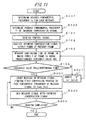
- FIG. 3 is a flow chart illustrating an exemplary process performed by the timing control unit 4 of the voice communication apparatus 1 in the first embodiment.
- the process illustrated in FIG. 3 is started at the opportunity of the control of the mixing control signal supplied to the timing control unit 4.
- the mixing control signal can be given to the timing control unit 4 by means of the operation of an unillustrated input device of the voice communication apparatus 1 performed by the user.
- the timing control unit 4 starts to accept the input of the judgment result of the voice interval/silent interval input from the voice interval detecting unit 2 (Step S1) , and the timing control unit 4 starts the monitoring of the silent interval (Step S2).
- Step S4 If the silent interval length is equal to or more than a threshold value TH1 previously held by the timing control unit 4 (YES in Step S3), the timing control unit 4 starts the mixing (Step S4).
- the timing control unit 4 reads the voice message from the message storage unit 3, and the mixing signal including the voice message is given to the mixing unit 5. If the silent interval length is equal to or less than the threshold value TH1 (NO in S3) , then the process is returned to Step S1, and the monitoring of the silent interval is continued.
- Step S4 the timing control unit 4 completes the process. In this way, the monitoring of the silent interval and the control of the mixing timing are executed every time when the mixing control signal is input.
- the voice interval detection process which is performed by the voice interval detecting unit 2, may be started at the opportunity of the input of the mixing control signal. That is, it is also allowable that the operation of the voice interval detecting unit 2 cooperates with the operation of the timing control unit 4.
- the silent interval is continued for equal to or more than the certain period of time, i.e., if the state, in which the user does not utter, is continued for the certain period of time, then the mixing of the voice message is started. Accordingly, it is possible to play back the voice message in the non-utterance interval of the user (interval A, FIG. 1 ) .
- the playback of the voice message is not started during the utterance of the user. Accordingly, it is possible to avoid such a situation that the user feels any difficulty to talk while worrying about the playback start timing of the voice message. Further, it is possible to prevent the voice message from being hardly heard due to the playback of the voice message during the utterance of the user.
- FIG. 4 is a diagram illustrating a voice communication apparatus 1A in the second embodiment.
- the voice communication apparatus 1A includes a voice interval detecting unit 2, a message storage unit 3, a timing control unit 4, and a mixing unit 5 in the same manner as in the first embodiment.
- the voice communication apparatus 1A further includes, as an outgoing conversation unit, a microphone M, an amplifier (AMP) 11, an encoding unit 12, and a packet transmitting unit 13.
- the microphone M collects utterances of a user of the voice communication apparatus 1A.
- the voice signal which is input into the microphone M, is amplified by the amplifier 11, and the signal is input as the outgoing conversation signal into the encoding unit 12.
- the outgoing conversation signal which is output from the amplifier 11, is also input into the voice interval detecting unit 2.
- the encoding unit 12 performs the analog/digital conversion (A/D conversion) process and the encoding compression process for the outgoing conversation signal, and the voice encoded signal is given to the packet transmitting unit 13.
- the packet transmitting unit 13 generates a packet including the voice encoded signal, and the packet is output as the transmitted packet.
- the transmitted packet is sent to the unillustrated network, and the transmitted packet is received by a terminal device (not illustrated) of another party in communication via the network. Another party in communication can listen to the voice of the user based on the transmitted packet received by the terminal device.
- the voice communication apparatus 1A includes, as an incoming conversation unit, a packet receiving unit 14, a decoding unit 15, the mixing unit 5, an amplifier (AMP) 16, and a speaker S.
- the packet which is transmitted from the terminal device of another party in communication and which includes the voice signal of another party in communication, arrives at the voice communication apparatus 1A via the network, and the packet is received as the received packet by the packet receiving unit 14.
- the packet receiving unit 14 extracts the voice encoded signal included in the received packet, and the signal is given to the decoding unit 15.
- the decoding unit performs the decoding process and the digital/analog conversion (D/A conversion) with respect to the voice encoded signal, and the obtained voice signal is output as the incoming conversation signal.
- the incoming conversation signal is input into the mixing unit 5 and the signal is output, while being subjected to the mixing with the voice message, if necessary, and then signal is amplified by the amplifier 16, followed by being connected to the speaker 16.
- the speaker S outputs the voice on the basis of the incoming conversation signal supplied from the amplifier.
- the user of the voice communication apparatus 1A can listen to the voice of another party in communication. Further, the user can also listen to the playback sound of the voice message subjected to the mixing, if necessary.
- the voice communication apparatus 1A further includes a switch SW for allowing the user to input the mixing control signal into the timing control unit 4.
- the switch SW is one of input devices of the voice communication apparatus 1A (IP telephone). The user can start up the timing control unit 4 by turning ON the switch SW.
- the amplifiers 11, 16, the encoding unit 12, the packet transmitting unit 13, the packet receiving unit 14, and the decoding unit 15 illustrated in FIG. 4 can be realized by using any exclusive or general purpose hardware.
- the encoding unit 12, the packet transmitting unit 13, the packet receiving unit 14, and the decoding unit 15 can be realized as the functions obtained such that a processor such as CPU or DSP executes the programs stored in a memory.
- FIG. 5 is a diagram illustrating an exemplary operation of the voice communication apparatus 1A in the second embodiment.
- the flow chart illustrated in FIG. 5 is started by receiving the control signal from the switch SW by the timing control unit 4 (Step S001) .
- the timing control unit 4 when receiving the control signal, gives, to the voice interval detecting unit 2, the instruction to start the judgment of the voice interval/silent interval of the outgoing conversation signal. Accordingly, the voice interval detecting unit 2 judges whether the interval is the voice interval or the silent interval for each of the frames by using, for example, the VAD (VAD: Voice Activity Detection) technique. And then, the voice interval detecting unit 2 outputs the judgment result of each of the frames to the timing control unit 4 (Step S002) .
- VAD Voice Activity Detection
- the timing control unit 4 receives the judgment result supplied from the voice interval detecting unit 2 to measure the continuing time of the silent interval (Step S003) .
- the timing control unit 4 judges whether or not the continuing time of the silent interval, i.e., the silent interval length is equal to or more than the predetermined threshold value TH1 (Step S004) . In this procedure, if the continuing time is less than the threshold value TH1 (NO in S004) , the process proceeds to Step S007.
- Symbol "n" indicates the sample number of the frame.
- the operation based on the flow chart illustrated in FIG. 5 is completed.
- the voice message and the voice of another party in communication based on the incoming conversation signal are output from the speaker S.
- the user can listen to the voice message.
- the voice message can provide, to the user, the subject or topic of the conversation with another party in communication.
- the user can make a favorable conversation with another party in communication.
- the function and the effect of the second embodiment are approximately the same as those of the first embodiment.
- the mixing of the voice message is started if the continuing time of the silent time, i.e., the silent interval length is equal to or more than the threshold value TH1. Accordingly, the playback of the voice message can be started in the interval A ( FIG. 1 ) in which the user does not utter. It is possible to secure the easy talking and the easy listening for the user.
- the voice interval detecting unit 2 starts the judging operation to judge the voice interval/silent interval in accordance with the instruction from the timing control unit 4. In place of this construction, it is also allowable that the operation is started in accordance with the input of the mixing control signal from the switch SW.
- the third embodiment has the common features common to those of the first and second embodiments. Therefore, an explanation will be principally made about different features, and the common features are omitted from the explanation.
- FIG. 6 illustrates an exemplary arrangement of the voice .communication apparatus 1B in the third embodiment.
- the voice communication apparatus 1B comprises a message storage unit 3, a timing control unit 4, and a mixing unit 5 in the same manner as in the first and second embodiments.
- An amplifier 16 and a speaker S are connected to the mixing unit 5 in the same manner as in the second embodiment.
- a talking time calculating unit 21 and a sound pressure analysis unit 22 as the analysis unit are connected to the timing control unit 4.
- a talking start signal is input into the talking time calculating unit 21.
- the talking start signal is input, for example, when the communication line is established between the voice communication apparatus 1B and the terminal device of another party in communication.
- the talking time calculating unit 21 has a timer for measuring the talking time. Every time when a predetermined period of time of the talking time elapses, the mixing control signal is input into the timing control unit 4. Accordingly, in the third embodiment, the timing control unit 4 is periodically started up every time when the predetermined time elapses.
- the incoming conversation signal is input into the sound pressure analysis unit 22.
- the sound pressure analysis unit 22 analyzes the sound pressure of the incoming conversation signal.
- the sound pressure information which is the analysis result, is input into the timing control unit 4.
- the sound pressure information includes the power for each of the frames of the incoming conversation signal.
- the voice communication apparatus 1B includes a microphone M and an amplifier 11 in the same manner as in the second embodiment. It is possible to output the outgoing conversation signal. However, the voice interval detecting unit 2 is omitted from the voice communication apparatus 1B. The outgoing conversation signal is not used for the mixing control of the voice message.
- the talking time calculating unit 21 and the sound pressure analysis unit 22 illustrated in FIG. 6 can be realized by using any exclusive or general purpose hardware.
- the talking time calculating unit 21 and the sound pressure analysis unit 22 can be realized as the functions obtained such that a processor such as CPU or DSP executes the programs stored in a memory.
- FIG. 7 illustrates a flow chart illustrating an exemplary operation of the voice communication apparatus 1B in the third embodiment.
- the flow chart illustrated in FIG. 7 is started by detecting, by the talking time calculating unit 12, the elapse of a predetermined time after the start of the talking on the phone and inputting the mixing control signal into the timing control unit 4 (Step S101) .
- the timing control unit 4 which receives the control signal, gives the startup instruction to the sound pressure analysis unit 22. Accordingly, the sound pressure analysis unit 22 analyzes the incoming conversation signal, and the sound pressure of the present frame, i.e., the power P is output to the timing control unit 4 (Step S102) .
- the power P can be calculated in accordance with the following expression (1).
- N the total number of samples in 1 frame.
- the timing control unit 4 receives the power P for each of the frames from the sound pressure analysis unit 22, and the timing control unit 4 measures the continuing time for the frame in which the power P of the frame is equal to or more than a threshold value TH3 previously held by the timing control unit 4 (Step S102) .
- the timing control unit 4 judges whether or not the continuing time is equal to or more than a threshold value TH4 previously held by the timing control unit 4 at the point in time at which the power P of the present frame is less than the threshold value TH3 (Step S104) . In this procedure, if the continuing time is less than the threshold value TH4 (NO in S104) , the process proceeds to Step S007.
- Step S005 the processes in Steps S005 to S007 illustrated in FIG. 7 are the same as or equivalent to those of the second embodiment.
- the mixing of the voice message is started. Accordingly, the voice message and the voice of another party in communication based on the incoming conversation signal are output from the speaker S in the same manner as in the second embodiment. The user can listen to the voice message. If the continuing time is less than the threshold value TH4, the mixing of the voice message is not performed.
- the talking time calculating unit 21 is provided in place of the switch SW.
- the control signal is input into the timing control unit 4 every time when the predetermined time elapses after the start of the talking on the phone. Accordingly, it is possible to periodically generate the timing of the mixing control of the voice message.
- timing control unit 4 can read the different voice message from the message storage unit 3 in every period. Accordingly, new subjects or topics can be provided as the voice messages as the conversation continues.
- the state, in which the sound pressure of the incoming conversation signal, i.e., the power P is equal to or more than the threshold value TH3 as described above, means that the incoming conversation signal includes the utterance of another party in communication.
- the user does not utter during the period in which the user hears the voice from another party in communication. Therefore, the mixing of the voice message, i.e., the playback thereof can be started in the interval A ( FIG. 1 ) in which the user does not utter.
- the sound pressure analysis unit 22 starts the judging operation for judging the voice interval/silent interval in accordance with the instruction from the timing control unit 4.
- the mixing control signal is input into both of the timing control unit 4 and the sound pressure analysis unit 22 and the both start the operations.
- the fourth embodiment has the common features common to those of the first, second, and third embodiments. Therefore, an explanation will be principally made about different features, and the common features are omitted from the explanation.
- FIG. 8 is a diagram illustrating an exemplary arrangement of the voice communication apparatus 1C in the fourth embodiment.
- the voice communication apparatus 1C includes a voice interval detecting unit 2, a message storage unit 3, a timing control unit 4, and a mixing unit 5 in the same manner as in the first and second embodiments.
- An amplifier 16 and a speaker S are connected to the mixing unit 5 in the same manner as in the second and third embodiments.
- the voice communication apparatus 1C includes a microphone M and an amplifier 11 in the same manner as in the second embodiment.
- the outgoing conversation signal which is output from the amplifier 11, is input into the voice interval detecting unit 2.
- the voice communication apparatus 1C includes a sound pressure analysis unit 22 in the same manner as in the third embodiment.
- the voice communication apparatus 1C includes a sound pressure adjusting unit 31 which is provided as the adjusting unit, a message selection unit 32 which is provided as the selection unit, and a spectrum analysis unit 33 which is provided as the voice quality analysis unit, as constitutive elements different from those of the first to third embodiments.
- the incoming conversation signal is input into the spectrum analysis unit 33.
- the spectrum analysis unit 33 performs the spectrum analysis for the incoming conversation signal, and the spectrum analysis result of the incoming conversation signal, i.e., the frequency characteristic is input as the analysis result into the message selection unit 32.
- the message selection unit 32 reads the voice message, i.e., the message signal corresponding to the analysis result of the spectrum analysis unit, and the signal is given to the sound pressure adjusting unit 31.
- a plurality of voice messages (message signals), which have the same content but which have different frequency spectrums (frequency characteristics), are previously stored in the message storage unit 3.
- the sound pressure adjusting unit 31 receives the average sound pressure of the incoming conversation signal output from the sound pressure analysis unit 22.
- the sound pressure adjusting unit 31 corrects the sound pressure of the message signal (voice message) depending on the average sound pressure, and inputs the corrected message signal into the timing control unit 4.
- the timing control unit 4 gives the corrected message signal as the mixing signal to the mixing unit 5, if the silent interval length is equal to or more than the threshold value TH1 on the basis of the judgment result of the voice interval detecting unit to judge whether the interval is the voice interval or the silent interval, in the same manner as in the second embodiment.
- the sound pressure adjusting unit 31, the message selection unit 32, and the spectrum analysis unit 33 illustrated in FIG. 8 can be realized by using any exclusive or general purpose hardware.
- the sound pressure adjusting unit 31, the message selection unit 32, and the spectrum analysis unit 33 can be realized as the functions obtained such that a processor such as CPU or DSP executes the programs stored in a memory.
- FIG. 9 illustrates a flow chart illustrating an exemplary operation of the voice communication apparatus 1C in the fourth embodiment.
- the average power Px and the frequency spectrum Sx [i] [f] of a plurality of message signals previously stored in the message storage unit 3 are determined beforehand (Step S201) .
- Symbol [i] described above is the identifier of the message signal, and symbol "f" indicates the frequency.
- the value of the average power Px may be previously held by the sound pressure adjusting unit 31.
- the value of the frequency spectrum Sx[i][f] may be previously held by the message selection unit 32.
- the values of the average power Px and the frequency spectrum Sx [i] [f] may be previously held by the timing control unit 4, and the values may be given to the sound pressure adjusting unit 31 and the message selection unit 32, if necessary. In this case, it is possible to omit Step S201.
- the sound pressure analysis unit 22 determines the average power Pr of the incoming conversation signal, and the average power Pr is input into the sound pressure adjusting unit 31, irrelevant to the presence or absence of the control signal.
- the spectrum analysis unit 33 performs the fast Fourier transform (FFT) with respect to the incoming conversation signal, analyzes the frequency spectrum of the incoming conversation signal, determines the frequency spectrum Sr[f] of the incoming conversation signal, and gives the frequency spectrum Sr[f] to the message selection unit 32 (Step S202) .
- FFT fast Fourier transform
- Steps S201 and S202 On the precondition of Steps S201 and S202, the processes or the operations of Steps S001 to S004 illustrated in FIG. 9 are performed.
- the processes of Steps S001 to S004 are the same as or equivalent to those of the second embodiment ( FIG. 5 ), any explanation of which is omitted.
- the operation of Step S007 illustrated in FIG. 9 is also the same as or equivalent to that of the second embodiment.
- Step S206 If the continuing time is equal to or more than the threshold value TH1 in Step S004, then the timing control unit 4 starts the reading of the message signal in Step S206, and the message selection instruction is given to the message selection unit 32.
- the message selection unit 32 reads a plurality of message signals as selection candidates from the message storage unit 3.
- the message selection unit 32 determines the square error d[i] between the frequency spectrum Sr[f] of the incoming conversation signal and the frequency spectrum Sx [i] [f] of the message signal for each of the messages to select the message signal in which the square error d [i] is minimized.
- the square error d[i] can be calculated in accordance with the following expression (2) .
- the message signal x' [i] [n] which is selected by the message selection unit 32, is given to the sound pressure adjusting unit 31.
- the sound pressure adjusting unit 31 controls the sound volume of the message signal so that the sound pressure of the message signal is smaller by a predetermined value than the average power Px of the incoming conversation signal.
- the predetermined value is, for example, 5 to 15 dB and preferably 10 dB.
- the corrected message signal x'' can be determined in accordance with the following expressions (3) and (4) .
- the timing control unit 4 gives the corrected message signal to the mixing control unit 5 in the same manner as in the second embodiment, and the mixing process is performed by the mixing control unit 5 (S008) .
- the fourth embodiment it is possible to obtain the function and the effect which are the same as or equivalent to those of the second embodiment.
- the plurality of voice messages (message signals), which have the same content but which have the different frequency spectrums as the parameters for indicating the voice qualities, are previously stored in the message storage unit 3, and one of the plurality of message signals, which has the frequency most different from the frequency of the incoming conversation signal, is selected. Further, the sound pressure is adjusted so that the sound volume of the selected message signal is smaller than the sound volume of the incoming conversation signal.
- the voice message which has the voice quality that is most different from that of the voice of the incoming conversation signal, is played back as the voice having the sound volume smaller than that of the voice of the incoming conversation signal, i.e., the voice of another party in communication.
- the voice message is played back as the voice having the sound volume smaller than that of the voice of the incoming conversation signal, i.e., the voice of another party in communication.
- the fifth embodiment has the common features common to those of the third embodiment. Therefore, an explanation will be principally made about different features, and the common features are omitted from the explanation.
- FIG. 10 is a diagram illustrating an exemplary arrangement of the voice communication apparatus 1D of the fifth embodiment.
- the voice communication apparatus 1C includes a message storage unit 3, a timing control unit 4, a mixing unit 5, a talking time calculating unit 21, and a sound pressure analysis unit 22 in the same manner as in the third embodiment. Further, the voice communication apparatus 1C includes a microphone M, amplifiers 11, 16, and a speaker S.
- the voice communication apparatus 1C includes a message processing unit 41 which is provided as the changing unit and a fundamental frequency analysis unit 42.
- the incoming conversation signal is input into the fundamental frequency analysis unit 42.
- the fundamental frequency analysis unit 42 analyzes the incoming conversation signal to determine the fundamental frequency (pitch frequency) of the incoming conversation signal which is given to the message processing unit 41.
- the message processing unit 41 adjusts the fundamental frequency of the message signal so that the fundamental frequency of the message signal (voice message) read from the message storage unit 3 is far from the fundamental frequency of the incoming conversation signal on the basis of the fundamental frequency of the incoming conversation signal, and the result is given to the timing control unit 4.
- the message processing unit 41 and the fundamental frequency analysis unit 42 illustrated in FIG. 10 can be realized by using any exclusive or general purpose hardware.
- the message processing unit 41 and the fundamental frequency analysis unit 42 can be realized as the functions obtained such that a processor such as CPU or DSP executes the programs stored in a memory.
- FIG. 11 illustrates a flow chart illustrating an exemplary operation of the voice communication apparatus 1D of the fifth embodiment.
- the average fundamental frequency fx for each of the messages stored in the message storage unit 3 is previously determined (Step S301) .
- the value of the average fundamental frequency fx may be previously held by the message processing unit 41.
- the value of the average stored frequency fx may be previously held by the timing control unit 4, and the value may be given to the message processing unit 41, if necessary. In this case, it is possible to omit Step S301.
- the fundamental frequency analysis unit 42 determines the average fundamental frequency fr of the incoming conversation signal irrelevant to the presence or absence of the mixing control signal and inputs the average fundamental frequency fr into the message processing unit 41 (Step S302) .
- Step S101 to S104 and S007 illustrated in FIG. 11 are the same as those in the second embodiment, any explanation of which is omitted. If the power P of the frame of equal to or more than the threshold value TH3 is continued for equal to or more than the threshold value TH4 in Step S104, the process proceeds to Step S303.
- Step S303 the timing control unit 4 starts the reading of the message signal, and the reading instruction is given to the message processing unit 41.
- the message processing unit 41 reads the message signal from the message storage unit 3, and the pitch conversion process is performed so that the fundamental frequency of the message signal is a predetermined output frequency fout [Hz] .
- FIG. 12 is an explanatory diagram of the pitch conversion process.
- the output frequency fout has two predetermined values of flow and fhigh. If the fundamental frequency fx of the message signal read from the message storage unit 3 is above the average fundamental frequency fr of the incoming conversation signal, flow is selected as fout. On the other hand, if the fundamental frequency fx is equal to or lower than the average fundamental frequency fr of the incoming conversation signal, fhigh is selected as fout. The process as described above is executed for each of the frames.
- the message signal, to which the pitch conversion process is applied is given to the timing control unit 4.
- the message signal, to which the pitch conversion process is applied is given as the mixing signal by the timing control unit 4 to the mixing unit 5.
- the mixing unit 5 performs the mixing of the incoming conversation signal with the message signal in the same manner as in the third embodiment.
- Step S305 the mixing process is continuously performed until the reading of the message signal from the message storage unit 3 is completed and the signal is given to the mixing unit 5 (Step S305) .
- the function and the effect which are the same as or equivalent to those of the third embodiment, are obtained. Further, if the fundamental frequency of the incoming conversation signal is higher than the fundamental frequency of the message signal, the fundamental frequency of the message signal is made higher than that of the incoming conversation signal. If the fundamental frequency of the incoming conversation signal is equal to or lower than the fundamental frequency of the message signal, the fundamental frequency of the message signal is made lower than that of the incoming conversation signal. Accordingly, it is possible to play back the voice message in which the fundamental frequency (pitch of voice) is greatly different from the pitch of voice of another party in communication. Therefore, the voice message can be heard with ease.
- the constructions of the embodiments explained above can be appropriately combined with each other.
Landscapes
- Engineering & Computer Science (AREA)
- Signal Processing (AREA)
- Telephone Function (AREA)
Applications Claiming Priority (1)
| Application Number | Priority Date | Filing Date | Title |
|---|---|---|---|
| PCT/JP2009/067165 WO2011039884A1 (fr) | 2009-10-01 | 2009-10-01 | Appareil de communication vocale |
Publications (2)
| Publication Number | Publication Date |
|---|---|
| EP2485461A1 true EP2485461A1 (fr) | 2012-08-08 |
| EP2485461A4 EP2485461A4 (fr) | 2013-11-27 |
Family
ID=43825738
Family Applications (1)
| Application Number | Title | Priority Date | Filing Date |
|---|---|---|---|
| EP09850074.7A Ceased EP2485461A4 (fr) | 2009-10-01 | 2009-10-01 | Appareil de communication vocale |
Country Status (4)
| Country | Link |
|---|---|
| US (1) | US8526578B2 (fr) |
| EP (1) | EP2485461A4 (fr) |
| JP (1) | JP5321687B2 (fr) |
| WO (1) | WO2011039884A1 (fr) |
Families Citing this family (1)
| Publication number | Priority date | Publication date | Assignee | Title |
|---|---|---|---|---|
| JP2022080074A (ja) * | 2020-11-17 | 2022-05-27 | トヨタ自動車株式会社 | 情報処理システム、情報処理方法及びプログラム |
Citations (2)
| Publication number | Priority date | Publication date | Assignee | Title |
|---|---|---|---|---|
| WO2008005046A1 (fr) * | 2006-06-30 | 2008-01-10 | Sony Ericsson Mobile Communications Ab | Dispositif de communication portatif et procédé de gestion simultanée de données audio à commutation de circuit et de données audio à commutation de paquets |
| US20080172229A1 (en) * | 2007-01-12 | 2008-07-17 | Brother Kogyo Kabushiki Kaisha | Communication apparatus |
Family Cites Families (15)
| Publication number | Priority date | Publication date | Assignee | Title |
|---|---|---|---|---|
| US5825855A (en) * | 1997-01-30 | 1998-10-20 | Toshiba America Information Systems, Inc. | Method of recognizing pre-recorded announcements |
| WO2000046789A1 (fr) | 1999-02-05 | 2000-08-10 | Fujitsu Limited | Detecteur de la presence d'un son et procede de detection de la presence et/ou de l'absence d'un son |
| JP2001175300A (ja) * | 1999-12-17 | 2001-06-29 | Yamaha Corp | 電話端末装置の音声合成装置 |
| JP3434487B2 (ja) * | 2000-05-12 | 2003-08-11 | 株式会社イサオ | 位置連動式チャットシステム、そのための位置連動式チャット方法、および、プログラムを記録したコンピュータ読み取り可能な記録媒体 |
| JP2003233387A (ja) * | 2002-02-07 | 2003-08-22 | Nissan Motor Co Ltd | 音声報知装置 |
| JP2004146894A (ja) * | 2002-10-22 | 2004-05-20 | Sharp Corp | 携帯端末装置及び音声制御プログラムを記録した記録媒体 |
| JP4093103B2 (ja) | 2003-04-18 | 2008-06-04 | 松下電器産業株式会社 | 電話装置 |
| JP3773917B2 (ja) * | 2003-05-15 | 2006-05-10 | 株式会社エヌ・ティ・ティ・ドコモ | 携帯通信装置、通信方法 |
| JP2005124062A (ja) | 2003-10-20 | 2005-05-12 | Matsushita Electric Ind Co Ltd | 電話装置 |
| JP4556574B2 (ja) | 2004-09-13 | 2010-10-06 | 日本電気株式会社 | 通話音声生成装置及び方法 |
| JP2006120018A (ja) * | 2004-10-22 | 2006-05-11 | Ricoh Co Ltd | 映像データ処理装置、映像データ処理方法、プログラム及び記録媒体 |
| JP4315894B2 (ja) * | 2004-11-30 | 2009-08-19 | シャープ株式会社 | 携帯端末装置 |
| JP2006174198A (ja) | 2004-12-17 | 2006-06-29 | Nippon Telegr & Teleph Corp <Ntt> | 音声再生端末、音声再生方法、音声再生プログラム、及び音声再生プログラムの記録媒体 |
| JP2007259427A (ja) * | 2006-02-23 | 2007-10-04 | Matsushita Electric Ind Co Ltd | 携帯端末装置 |
| JP2007333603A (ja) * | 2006-06-16 | 2007-12-27 | Sony Corp | ナビゲーション装置、ナビゲーション装置の制御方法、ナビゲーション装置の制御方法のプログラム、ナビゲーション装置の制御方法のプログラムを記録した記録媒体 |
-
2009
- 2009-10-01 JP JP2011534018A patent/JP5321687B2/ja not_active Expired - Fee Related
- 2009-10-01 EP EP09850074.7A patent/EP2485461A4/fr not_active Ceased
- 2009-10-01 WO PCT/JP2009/067165 patent/WO2011039884A1/fr active Application Filing
-
2012
- 2012-03-30 US US13/435,077 patent/US8526578B2/en not_active Expired - Fee Related
Patent Citations (2)
| Publication number | Priority date | Publication date | Assignee | Title |
|---|---|---|---|---|
| WO2008005046A1 (fr) * | 2006-06-30 | 2008-01-10 | Sony Ericsson Mobile Communications Ab | Dispositif de communication portatif et procédé de gestion simultanée de données audio à commutation de circuit et de données audio à commutation de paquets |
| US20080172229A1 (en) * | 2007-01-12 | 2008-07-17 | Brother Kogyo Kabushiki Kaisha | Communication apparatus |
Non-Patent Citations (1)
| Title |
|---|
| See also references of WO2011039884A1 * |
Also Published As
| Publication number | Publication date |
|---|---|
| US8526578B2 (en) | 2013-09-03 |
| JP5321687B2 (ja) | 2013-10-23 |
| WO2011039884A1 (fr) | 2011-04-07 |
| US20120189108A1 (en) | 2012-07-26 |
| EP2485461A4 (fr) | 2013-11-27 |
| JPWO2011039884A1 (ja) | 2013-02-21 |
Similar Documents
| Publication | Publication Date | Title |
|---|---|---|
| CN102254556B (zh) | 基于听者和说者的讲话风格比较估计听者理解说者的能力 | |
| JP4713111B2 (ja) | 発話区間検出装置、音声認識処理装置、送信システム、信号レベル制御装置、発話区間検出方法 | |
| EP4020469A1 (fr) | Procédé et appareil de traitement de mélange audio d'appel, support d'enregistrement et dispositif informatique | |
| US8031857B2 (en) | Methods and systems for changing a communication quality of a communication session based on a meaning of speech data | |
| EP2928164A1 (fr) | Procédé et dispositif de transmission pour données vocales | |
| EP3444819B1 (fr) | Procédé et terminal de traitement en cascade de signal vocal, et support de stockage lisible par ordinateur | |
| WO2012154798A1 (fr) | Détection du caractère direct d'un locuteur | |
| JP5051882B2 (ja) | 音声対話装置、音声対話方法及びロボット装置 | |
| US10504538B2 (en) | Noise reduction by application of two thresholds in each frequency band in audio signals | |
| US10540983B2 (en) | Detecting and reducing feedback | |
| EP2743923B1 (fr) | Dispositif et procédé de traitement vocal | |
| JP5251588B2 (ja) | 携帯電話端末装置及び通話伝達の判断方法 | |
| EP2485461A1 (fr) | Appareil de communication vocale | |
| Nogueira et al. | Artificial speech bandwidth extension improves telephone speech intelligibility and quality in cochlear implant users | |
| Pulakka et al. | Conversational quality evaluation of artificial bandwidth extension of telephone speech | |
| US20080059161A1 (en) | Adaptive Comfort Noise Generation | |
| Grundlehner et al. | Performance assessment method for speech enhancement systems | |
| US20060106603A1 (en) | Method and apparatus to improve speaker intelligibility in competitive talking conditions | |
| JP2005077970A (ja) | 音声品質客観評価装置および音声品質客観評価方法 | |
| JP2006235102A (ja) | 音声処理装置および音声処理方法 | |
| JP2004252085A (ja) | 音声変換システム及び音声変換プログラム | |
| JP4116955B2 (ja) | 音声品質客観評価装置および音声品質客観評価方法 | |
| JP5853540B2 (ja) | 音声通信装置及びプログラム | |
| JP2002300259A (ja) | 音声通話装置の評価試験方法及びシステム | |
| JP2005039501A (ja) | 携帯電話録音サービスシステム、方法およびプログラム |
Legal Events
| Date | Code | Title | Description |
|---|---|---|---|
| PUAI | Public reference made under article 153(3) epc to a published international application that has entered the european phase |
Free format text: ORIGINAL CODE: 0009012 |
|
| 17P | Request for examination filed |
Effective date: 20120330 |
|
| AK | Designated contracting states |
Kind code of ref document: A1 Designated state(s): AT BE BG CH CY CZ DE DK EE ES FI FR GB GR HR HU IE IS IT LI LT LU LV MC MK MT NL NO PL PT RO SE SI SK SM TR |
|
| DAX | Request for extension of the european patent (deleted) | ||
| A4 | Supplementary search report drawn up and despatched |
Effective date: 20131030 |
|
| RIC1 | Information provided on ipc code assigned before grant |
Ipc: H04M 1/60 20060101AFI20131024BHEP Ipc: G10L 21/00 20130101ALN20131024BHEP |
|
| 17Q | First examination report despatched |
Effective date: 20160803 |
|
| REG | Reference to a national code |
Ref country code: DE Ref legal event code: R003 |
|
| STAA | Information on the status of an ep patent application or granted ep patent |
Free format text: STATUS: THE APPLICATION HAS BEEN REFUSED |
|
| 18R | Application refused |
Effective date: 20170722 |