EP2483628B1 - System und verfahren zur umlenk- und ausrichtungssteuerung bei flugzeugen - Google Patents
System und verfahren zur umlenk- und ausrichtungssteuerung bei flugzeugen Download PDFInfo
- Publication number
- EP2483628B1 EP2483628B1 EP10785238.6A EP10785238A EP2483628B1 EP 2483628 B1 EP2483628 B1 EP 2483628B1 EP 10785238 A EP10785238 A EP 10785238A EP 2483628 B1 EP2483628 B1 EP 2483628B1
- Authority
- EP
- European Patent Office
- Prior art keywords
- thruster
- thrusters
- commands
- values
- matrix
- Prior art date
- Legal status (The legal status is an assumption and is not a legal conclusion. Google has not performed a legal analysis and makes no representation as to the accuracy of the status listed.)
- Active
Links
Images


Classifications
-
- F—MECHANICAL ENGINEERING; LIGHTING; HEATING; WEAPONS; BLASTING
- F42—AMMUNITION; BLASTING
- F42B—EXPLOSIVE CHARGES, e.g. FOR BLASTING, FIREWORKS, AMMUNITION
- F42B10/00—Means for influencing, e.g. improving, the aerodynamic properties of projectiles or missiles; Arrangements on projectiles or missiles for stabilising, steering, range-reducing, range-increasing or fall-retarding
- F42B10/60—Steering arrangements
- F42B10/66—Steering by varying intensity or direction of thrust
-
- B—PERFORMING OPERATIONS; TRANSPORTING
- B64—AIRCRAFT; AVIATION; COSMONAUTICS
- B64G—COSMONAUTICS; VEHICLES OR EQUIPMENT THEREFOR
- B64G1/00—Cosmonautic vehicles
- B64G1/22—Parts of, or equipment specially adapted for fitting in or to, cosmonautic vehicles
- B64G1/24—Guiding or controlling apparatus, e.g. for attitude control
- B64G1/26—Guiding or controlling apparatus, e.g. for attitude control using jets
-
- F—MECHANICAL ENGINEERING; LIGHTING; HEATING; WEAPONS; BLASTING
- F42—AMMUNITION; BLASTING
- F42B—EXPLOSIVE CHARGES, e.g. FOR BLASTING, FIREWORKS, AMMUNITION
- F42B15/00—Self-propelled projectiles or missiles, e.g. rockets; Guided missiles
- F42B15/01—Arrangements thereon for guidance or control
Definitions
- the present invention relates to a system and method of control for flight vehicles, including missiles, kill vehicles, and space craft.
- DAC Divert and Attitude control
- a typical DAC system includes thrusters that are used for divert maneuvers, attitude control, and stabilizing the flight vehicle.
- any burning of a thruster continuously creates pitch, yaw and roll moments.
- the DAC system needs to be able to compensate for these recurring moments. If the control is not accurate and fast enough to compensate for these moments, the flight vehicle may overshoot or undershoot the desired path. Additionally, pointing errors can result in missed targets. Finally, a system with marginal stability may waste fuel.
- a system and method for thruster control in a flight vehicle.
- the system and method uses a proportional derivative control technique to determine thrust commands in a Divert and Attitude control (DAC) system.
- the proportional derivative control system is configured to receive pitch, roll and yaw commands as inputs, and generate thrust commands as outputs.
- the performance of the proportional derivative controller is such that the thrust commands can achieve the desired attitude angles quickly and with reduced fuel consumption.
- control system receives line-of-sight rate commands and operates to reduce pointing error. Additionally, in one embodiment the control system receives center of gravity shift data and operates to cancel moments resulting from the center of gravity shift due to fuel burn and other causes.
- a system and method for thruster control in a flight vehicle.
- the system and method uses a proportional derivative control technique to determine thrust commands in a Divert and Attitude control (DAC) system.
- the proportional derivative technique uses feedback of the quaternion of the attitude error and angular velocity to globally stabilize the attitude of a ridged body. Additionally, angular velocity feedback is provided by a nonlinear filter of the quaternion, thus removing the need for direct angular velocity measurement.
- the proportional derivative control system is configured to receive pitch, roll and yaw commands as inputs, and generate thrust commands as outputs.
- the performance of the proportional derivative controller is such that the thrust commands can achieve the desired attitude angles quickly and with reduced fuel consumption.
- the control system receives line-of-sight rate commands and operates to reduce pointing error. Additionally, in one embodiment the control system receives center of gravity shift data and operates to cancel moments resulting from the center of gravity shift due to fuel burn and other causes.
- the control system can efficiently control a variety of thrusters, including asymmetric thrusters having different moment arms.
- the control system is particularly suitable to the control of DAC systems with asymmetric thrusters that are configured for attitude control.
- a system has asymmetric thrusters if thrusters in the system have different moment arms.
- Such asymmetric thrusters can have significant advantages.
- the asymmetric arrangement of the thrusters allows a lower number of thrusters to be used for attitude control. For example, while a symmetric thruster arrangement would typically require six thrusters for complete attitude control, a set of asymmetric thrusters can provide attitude control with as few as four thrusters. This reduction in the required number of thrusters can significantly reduce the cost and complexity of flight vehicles.
- the proportional derivative controller is able to control asymmetric thrusters to efficiently compensate for these moments while reducing overall fuel consumption.
- the proportional derivative controller can facilitate the use of cost effective asymmetric thrusters in a wide variety of applications.
- the flight vehicle 100 is exemplary of the type of vehicles in which the controller can be utilized, which can include flight vehicles such as missiles, kill vehicles (KV) or space craft.
- the flight vehicle 100 uses a Divert and Attitude control (DAC) system during flight for both major control (i.e., divert maneuvers) and attitude control (i.e., pitch, yaw and roll control).
- DAC Divert and Attitude control
- the flight vehicle is oriented with its body axis 102 along a roll axis (in FIG.
- the DAC system uses four major thrusters 104 for divert control, and four attitude control thrusters 106 for pitch (rotation about the Y-axis), yaw (rotation about the Z-axis) and roll control (rotation about the X-axis).
- the attitude control thrusters 106 are asymmetric, allowing them to perform overlapping pitch, roll and yaw maneuvers. Specifically, because they are asymmetric, the firing of any of the four thrusters 106 will create pitch, roll and yaw moments in the vehicle 100. Because such a system only uses four attitude thrusters, such a system is relatively inexpensive when implemented with fixed impulse thrusters, and yet can provide high speed maneuverability. Thus, the use of simple asymmetric thrusters can provide a reliable and cost effective solution.
- the thrusters 106 are mounted on the flight vehicle 100 away from the vehicle's center of gravity. Furthermore, the thrusters 106 include a first pair (106A, 106B) that are closer to the center of gravity, and a second pair (106C, 106D) that are farther from the center of gravity. Additionally, these four thrusters are not aligned with Y-axis or Z-axis, and are instead located between Y-axis and Z-axis. This makes the performance of the thrusters asymmetric, meaning that any thrust of any thruster will create pitch, roll and yaw moments.
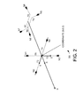
- FIGS. 2 and 3 a specific example of the DAC system with major and attitude thrusters is illustrated.
- the thrust vectors for exemplary sets of four major divert thrusters T1, T2, T3, and T4 (e.g., thrusters 104) and four attitude control thrusters T5, T6, T7, and T8 (e.g. thrusters 106) are illustrated in a body diagram and labeled with a coordinate system.
- the four major control thrusters T1, T2, T3, and T4 create four thrust vectors labeled N1, N2, N3, and N4 (with the corresponding arrows indicating the direction of the thrust vector).
- the four attitude control thrusters T5, T6, T7, and T8 create four thrust vectors labeled N5, N6, N7 and N8.
- the thrust vectors created by the four attitude control thrusters are asymmetric, meaning the firing of the thrusters will create different moment arms.
- the thrusters T5, T6, T7, and T8 are not aligned with Y-axis or Z-axis, and are instead located between Y-axis and Z-axis. Furthermore, the T5 and T7 are closer to the center of gravity than T6 and T8, and thus the firing of the thrusters will create different moments.
- a table 300 shows the exemplary thruster locations and directions relative to the center of gravity for thrusters T1-T8.
- MTA_Z is the distance from (0,0,0) point along the Z-axis to thruster T1
- MTA_Y is the distance from (0,0,0) point along the Y-axis to thruster T2.
- x1 is the distance from the (0,0,0) point to thrusters N5 and N7 along the X-axis
- x2 is the distance from the (0,0,0) point to thrusters T6 and T8 along the X-axis.
- y1 is the location distance of the attitude thrusters T5, T6, T7 and T8 along the Y-axis perpendicular to the X-axis.
- the performance of the thrusters is asymmetric, and any use of any thruster will create pitch, yaw and roll moments. Because of this, if the thruster control is not accurate and fast enough to compensate for the created moments, the vehicle will overshoot or undershoot. Such a system will have marginal stability, waste fuel and have a large pointing error.
- each thruster in FIGS 1-3 is just one example of the type of configurations that can use asymmetric thrusters for attitude control.
- each thruster is preferably very simple.
- a configuration of fixed-impulse thrusters is highly effective and simplifies attitude control.
- single-shot fixed-impulse thrusters provide a highly reliable and inexpensive solution to perform a single attitude control maneuver.
- a control system issues thrust commands calculated to generate specified attitude control maneuver.
- these thrust commands are in the form of pulse width modulated signals that indicate the required time of thrust during each cycle to achieve the desired maneuvers.
- the system constantly receive the pitch, yaw and roll angles, typically from an inertial navigation system, and use these values to determine the thrust times needed each cycle for each individual thruster. For example, to stop movement of the flight vehicle, the sum of the rotational moments in each of the pitch and yaw planes must be zero.
- Such maneuvers require that the pulse width modulation timing of firing be well controlled. For example, if the thrust times for each cycle are longer than the required, the missile will over pitch, over yaw and/or over rotate. Conversely, if the thrust times for each cycle are shorter than required the vehicle will under pitch, under yaw and/or under rotate.
- a first embodiment of a thruster control system 400 is illustrated.
- the thruster control system 400 would be implemented by a processor.
- the term "processor" is defined to include one or more processing elements that are adapted to perform the recited operations.
- a processor comprise all or part of one or more integrated circuits, firmware code, and/or software code that receive electrical signals from various sources and generate appropriate responses.
- all processing elements that comprise the processor are located together.
- the elements of a processor may spread across multiple devices in multiple locations.
- the control system 400 uses a coupling matrix 401 and a moment matrix 402 to determine thrust commands for a Divert and Attitude control (DAC) system in a flight vehicle.
- the thruster control system 400 receives pitch, roll and yaw commands 404, center of gravity shift 406, line-of-sight rate commands 408, and angular velocities 409 as inputs. From these, the thruster control system 400 generates thruster commands 410 as outputs.
- the pitch, roll and yaw commands 404 are generated by a tracking system which compares the current pitch, roll and yaw to a desired pitch, yaw and roll to determine the commands.
- the line-of-sight rate commands 408 and angular velocities 409 are generated by the guidance system and are typically in the form of radians per second.
- the center of gravity shift 406 is typically generated by estimating the CG shift distance resulting from fuel burn, and is in units of length.
- the performance of the thruster controller system 400 is such that the thrust commands can achieve the desired attitude angles quickly and with reduced fuel consumption. Additionally, the control system 400 operates to reduce pointing error of the flight vehicle and cancel moments resulting from the center of gravity shift due to fuel burn and other causes.
- the thruster control system 400 can efficiently control a variety of thrusters, and is particularly suitable to the control of DAC systems with asymmetric thrusters that are configured for attitude control. As asymmetric thrusters can control attitude with a lower number of thrusters, the thruster control system 400 can provide a cost effective solution to attitude control in a flight vehicle. Specifically, the thruster control system 400 can control the asymmetric thrusters to efficiently compensate for created moments while reducing overall fuel consumption.
- the thruster control system 400 uses the coupling matrix 401 and the moment matrix 402 to determine the thrust commands for a DAC system in a flight vehicle.
- the derivation of example coupling matrixes and moment matrixes will now be discussed.
- the coupling matrix 401 is determined for a particular thruster arrangement by calculating the thruster moments in the X, Y and Z axes for a flight vehicle.
- the coupling matrix 401 can be determined by calculating flight vehicles moment vectors as the cross product of position matrix and thruster force matrix for the particular thruster arrangement, and summing the thruster moments in the X, Y and Z axes.
- M B ⁇ T
- M a vehicle moment matrix
- T a thrust command matrix
- B a coupling matrix
- each element in the thrust matrix T corresponds to a generated thrust command for one of the thrusters in the DAC system.
- the moment matrix M is preferably configured to account for various moments that operate on the flight vehicle. For example, to account for position commands, rate feedback, line-of-sight rate commands, angular velocities and center of gravity shifts.
- the thruster control system 400 can provide efficient and accurate attitude control for a flight vehicle.
- TM sin A ⁇ 5 * y * T ⁇ 5 sin A ⁇ 5 * Xa * T ⁇ 5 cos A ⁇ 5 * Xa * T ⁇ 5 sin A ⁇ 6 * y * T ⁇ 6 - sin A ⁇ 6 * Xb * T ⁇ 6 cos A ⁇ 6 * Xb * T ⁇ 6 sin A ⁇ 7 * y * T ⁇ 7 - sin A ⁇ 7 * Xa * T ⁇ 7 - cos A ⁇ 7 * Xa * T ⁇ 7 - sin A ⁇ 8 * y * T ⁇ 8 sin A ⁇ 8 * Xb * T ⁇ 8 - cos A ⁇ 8 * Xb * T ⁇ 8 - cos A ⁇ 8 * Xb * T ⁇ 8 - cos A ⁇ 8 * Xb * T ⁇ 8 - cos A ⁇ 8 * Xb * T ⁇ 8 - cos A ⁇ 8 * Xb * T ⁇ 8 - cos A
- Equation 7 defines a specific implementation of the general relationship described in Equation 2 above.
- this equation describes a coupling matrix B that defines the relationship between the thrust provided by the thrusters and the moments generated on the flight vehicle.
- the coupling matrix B and the vehicle moment matrix M can be used to determine the thrust commands.
- the vehicle moment matrix M is configured to account for position commands, rate feedback terms, line-of-sight rate terms, and angular velocities.
- Kp 1 , Kp 2 and Kp 3 are positive scalers for position gain in the X, Y and Z coordinates
- Kv 1 , Kv 2 and Kv 3 are positive scalars for velocity gain in the X, Y and Z coordinates
- ⁇ r, ⁇ p, ⁇ y are position commands for roll, pitch and yaw respectively
- ⁇ x , ⁇ y , ⁇ z are angular velocity feedback terms
- ⁇ x , ⁇ y , ⁇ z are the line-of-sight rate terms.
- each element in the moment matrix M ACS defines a proportional derivative expression of
- the gain scalars Kp 1 , Kp 2 , Kp 3 , Kv 1 , Kv 2 , and Kv 3 would be calculated based on the physical dimensions of the flight vehicle. Such calculations may be done by trial and error to optimize system performance.
- the roll ( ⁇ r ) , pitch ( ⁇ p ) and yaw ( ⁇ y ) commands would typically be provided by the vehicle system tracker, which receives attitude data from the inertial guidance system and target reference data, and generates the appropriate commands. These commands would typically be a delta angular position value for each command.
- the feedback terms for each coordinate direction ( ⁇ x , ⁇ y , ⁇ z ) would typically be of angular velocity and would generated by the inertial navigation system (INS).
- the line-of-sight rate terms represent the rate of change of the line-of-sight rate commands used to track the desired target, and serve as feed forward terms that reduces pointing error in the system.
- These line-of-sight rate terms are added to reduce pointing error that could otherwise result from the pointing error being within the dead-band region where attitude control thrusters are not activated. Because of this, the use of the line-of-sight rate terms additionally reduces the chance that the attitude control thrusters will overcompensate when the pointing error exceeds the dead band region and result in an overshoot response.
- These values would typically be generated by the guidance system, and would typically be in the form of radians per second.
- an additional feed forward term for shifts in vehicle center of gravity is added.
- the center of gravity of the vehicle migrates as fuel is burned and weight decreases.
- the additional center of gravity feed forward term is added to the moment matrix M to counter these moments.
- rcx is again the distance the center of gravity has migrated along the vehicle X-axis from the divert plane
- rcy is the distance the center of gravity has migrated along the vehicle Y-axis from the divert plane
- rcz is the distance the center of gravity has migrated along the vehicle Z-axis from the divert plane.
- the use of the M DIVERT matrix can be combined with the M ACS matrix to provide a single vehicle moment matrix that accounts for position commands, rate feedback terms, line-of-sight rate terms, angular velocities, and the center of gravity changes.
- the matrix defined by [ M ACS - M DIVERT ] is the moment matrix used to generate the thrust commands.
- the exemplary thruster command matrix T includes more elements than the product of the coupling matrix B and moment matrix M.
- the thruster command matrix includes 4 elements, while the moment and coupling matrix products define three elements.
- equation 12 defines a problem with four unknowns and three equations.
- solving for four unknowns with three equations results in infinite solutions.
- the thruster control system is preferably implemented with appropriate constraints that are selected to provide manageable solutions that can be implemented in the thruster control system.
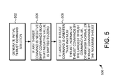
- the first step 502 is to generate initial thrust value solutions. This is done by multiplying the matrices defined in equation 12 above. Specifically, multiplying the moment matrix [ M ACS - M DIVERT ] by the pseudo inverse of the coupling matrix [ B ] -1 generates a set of initial thrust command values. These thrust values will then used in steps 504 and 506 to generate the final optimized thrust values.
- the next step 504 is to shift the array of thrust values if any thrust command values are negative.
- at least one negative thrust command value is shifted to zero. This is done by adding a constant vector to all thrust values, where the vector results in the shifting of a negative value to zero.
- This step also constrains the values of the thruster command matrix Tto positive quantities. As a typical thruster can only generate positive thrust, and is limited to the defined maximum thrust, this step helps constrain the generated thrust values that are actually available for use.
- step 506 if the largest thrust command is greater than the maximum thrust, the thrust commands are normalized by the largest thrust command values. Otherwise, the thrust commands are normalized the maximum thrust.
- the thrusters can only provide a maximum thrust level, but the design requires different amounts of impulses.
- the thrusters burn for a certain time and rapidly open and close thruster valves per duty cycle. This is typically referred to as a pulse width modulation technique.
- the thruster values are normalized to a proportion of the duty cycle for each command. The proportion is the amount of the duty cycle the thruster burns to obtain the desired impulse.
- step 506 if one of the thrust command values exceeds the maximum thrust that can be generated by the thrusters, then the normalization results in that thrust command being scaled down to the maximum available thrust, and the other values scaled proportionally. Thus, the largest thrust command would be scaled to a value of 1, which indicates the application of full thrust over the full duty cycle.
- the thrust commands are normalized by the maximum thrust.
- the largest command will not equal the maximum thrust command, but will be some proportion less than the maximum thrust value.
- Step 506 results in normalizing that provides optimal performance with fast response command calculation and increased efficiency.
- the control system uses less fuel, and provides greater efficiency to its tracking system.
- step 504 shifts the values of the thruster such that at least one value is shifted to zero and all other values are non-negative.
- the thrust values can be shifted to by adding the appropriate constant vector to the thrust command matrix.
- the thrust values [10, 5, 0, -5] can be shifted to [15, 10, 5, 0]. Again, this adding of a constant vector adds zero moment to the system, and the resulting shifted values are thus still an appropriate solution.
- the thrust commands are normalized by the largest thrust command values. Otherwise, the thrust commands are normalized the maximum thrust.
- the thruster T5 will be burn for the full duty cycle, T6 will burn for approximately 67 percent of the duty cycle, T7 will burn for 33 percent of the duty cycle, and T8 will not burn.
- the generated thrust command is passed to a pulse width modulator (PWM), which computes the modulation command.
- PWM pulse width modulator
- the PWM generates a signal such that the value is open for more than one sampling time if the thrust command is equal to or greater than the sampling time. Otherwise, the valve will operate at its specified cycle rate (e.g., 180 Hz)
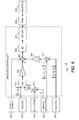
- the thrust controller 600 receives data from center-of gravity (CG) shift moment system 620, tracker system 622, roll offset 624, inertial navigation system 626 and guidance system 628.
- the controller 600 itself includes amplifiers 602 and 604, summers 608, 610 and 612, multiplexer 611, coupling matrix 606, and solver 607.
- the controller 600 implements the matrix control techniques described above, and output optimized thrust commands to a pulse width modulation system 628, which controls the firing of thrusters 630.
- the CG shift moment system tracks changes in the flight vehicle's center of gravity due to fuel burn. This data is typically in the form of a length measurement corresponding to the current center of gravity, which can be used to compensate for changes in the center of gravity.
- the tracker system 622 compares the measured pitch and yaw values to a desired pitch and yaw, and generates delta values ( ⁇ p, ⁇ y ) that represent the difference. These delta values for pitch and yaw ( ⁇ p, ⁇ y ) are passed to the multiplexer 611.
- the roll offset 624 provides a default roll command. For example, in some cases a constant -45 degree roll is desirable, and the roll offset 624 can provide such an offset to summer 612.
- the inertial navigation system 626 provides a body roll angle ( ⁇ ), which is added to the roll offset in summer 612 to provide a delta roll value ( ⁇ r ) .
- the delta roll value ( ⁇ r ) is passed to the multiplexer 611, where it is combined with the delta pitch ( ⁇ p) and delta yaw ( ⁇ y ) values. The result in then passed to the amplifier 602.
- the inertial navigation system 626 also provides feedback terms in the form of angular velocities ( ⁇ x , ⁇ y , ⁇ z ) to the summer 610.
- the guidance system 628 provides line-of-sight rate terms ( ⁇ x , ⁇ y , ⁇ z ) in the form of radians per second to the summer 610. These values are combined by the summer 610 and passed to the amplifier 604.
- the amplifiers 602 and 604 amplify the incoming signals by the position gain vector Kp and the velocity gain vector Kv respectively.
- the position gain vector Kp includes three scalar elements Kp 1 , Kp 2 , and Kp 3
- the velocity gain vector Kv includes three scalar elements Kv 1 , Kv 2 , and Kv 3 . The results are then added together with the CG shift moment by summer.
- This amplification and multiplication performs operations that effectively generate a moment matrix [ M ACS - M DIVERT ], as was described above. These results are then multiplied by the inversed coupling matrix [ B ] -1 . The result of the matrix multiplication is to generate an array of initial thrust command values [ T ], one for each of the attitude control thruster.
- the initial thrust command values are passed to the solver 607.
- the solver uses the techniques described above with reference to FIG. 5 to generate optimized thrust commands. This includes shifting the thrust values to eliminate negative values and normalizing by largest thrust command or maximum thrust as appropriate. This results in optimized thrust commands that are passed to the Pulse Width Modulator 628 to generate the final pulse width modulated control signals for the thrusters 630.
- the result of the operation of the thrust controller 600 is thrust commands that can achieve the desired attitude angles quickly, cancel moments resulting from center of gravity shifts, with reduced fuel consumption and reduces pointing error.
- Such a system is particularly suitable to the control of DAC systems with asymmetric thrusters that are configured for attitude control.
Landscapes
- Engineering & Computer Science (AREA)
- General Engineering & Computer Science (AREA)
- Chemical & Material Sciences (AREA)
- Combustion & Propulsion (AREA)
- Remote Sensing (AREA)
- Aviation & Aerospace Engineering (AREA)
- Radar, Positioning & Navigation (AREA)
- Physics & Mathematics (AREA)
- Fluid Mechanics (AREA)
- Control Of Position, Course, Altitude, Or Attitude Of Moving Bodies (AREA)
Claims (15)
- Triebwerksteuersystem (400) für einen Flugkörper (100), das Folgendes umfasst:eine asymmetrische Anordnung von lediglich vier Triebwerken (106), die eine Nick-, Gier- und Rollsteuerung bereitstellen; undeinen Prozessor, der dazu ausgelegt ist, Nick-, Gier- und Rollbefehle zu empfangen und als Antwort auf die Nick-, Gier- und Rollbefehle mehrere Triebwerksbefehle in einer Schubbefehlsmatrix T für die vier Triebwerke unter Verwendung einer Matrixsteuertechnik zu erzeugen, wobei der Prozessor T = [B]-1M berechnet, wobei M eine Fahrzeugmomentenmatrix ist, B eine Kopplungsmatrix ist, die die Beziehung zwischen dem Schub, der von den Triebwerken geliefert wird, und den Momenten, die an dem Flugkörper erzeugt werden, definiert, und [B]-1 die Pseudoinverse der Kopplungsmatrix B ist.
- Triebwerksteuersystem nach Anspruch 1, das ferner Folgendes umfasst:mehrere Umlenktriebwerke (104), um eine Umlenksteuerung bereitzustellen,wobei der Prozessor ferner dazu ausgelegt ist, Daten zu empfangen, die die Schwerpunktverschiebungsmomente in dem Flugkörper angeben, während die Umlenktriebwerke laufen, undwobei der Prozessor ferner dazu ausgelegt ist, die Schwerpunktverschiebungsmomente mit den mehreren Triebwerksbefehlen durch Subtrahieren einer Umlenkmomentenmatrix von der Momentenmatrix M auszugleichen.
- Triebwerksteuersystem nach Anspruch 1, wobei der Prozessor ferner dazu ausgelegt ist, Sichtliniengeschwindigkeitsbefehle für den Flugkörper zu empfangen, und wobei der Prozessor ferner dazu ausgelegt ist, die mehreren Triebwerksbefehle als Antwort auf die Sichtliniengeschwindigkeitsbefehle unter Verwendung der Matrixsteuertechnik zu erzeugen.
- Triebwerksteuersystem nach Anspruch 1, wobei der Prozessor dazu ausgelegt ist, die mehreren Triebwerksbefehle für die vier Triebwerke durch Erzeugen eines Felds von Triebwerkswerten für die Schubbefehlsmatrix T und dann, wenn irgendwelche Schubbefehlswerte negativ sind, Addieren eines konstanten Vektors zu allen Triebwerkswerten, so dass alle Triebwerkswerte positive Werte oder gleich null sind, zu erzeugen.
- Triebwerksteuersystem nach Anspruch 1, wobei der Prozessor dazu ausgelegt ist, die mehreren Triebwerksbefehle für die vier Triebwerke durch Erzeugen einer Anordnung von Triebwerkswerten und Addieren eines konstanten Vektors zu allen Triebwerkswerten, so dass mindestens ein Triebwerkswert auf null verschoben wird, zu erzeugen.
- Triebwerksteuersystem nach Anspruch 5, wobei der Prozessor dazu ausgelegt ist, die mehreren Triebwerksbefehle für die vier Triebwerke ferner durch Normieren des Felds von Triebwerkswerten auf einen größten Triebwerkswert in dem Feld von Triebwerkswerten zu erzeugen, wenn der größte Triebwerkswert einen Maximalwert überschreitet.
- Triebwerksteuersystem nach Anspruch 6, wobei der Prozessor dazu ausgelegt ist, die mehreren Triebwerksbefehle für die vier Triebwerke ferner durch Normieren des Felds von Triebwerkswerten auf den Maximalwert zu erzeugen, wenn der größte Triebwerkswert den Maximalwert nicht überschreitet.
- Verfahren zur Triebwerksteuerung in einem Flugkörper (100), das die folgenden Schritte umfasst:Bereitstellen einer asymmetrischen Anordnung von lediglich vier Triebwerken (106) für den Flugkörper, die eine Nick-, Gier- und Rollsteuerung bereitstellen;Empfangen von Nick-, Gier- und Rollbefehlen;Erzeugen mehrerer Triebwerksbefehle in einer Schubbefehlsmatrix T für die vier Triebwerke als Antwort auf die Nick-, Gier- und Rollbefehle unter Verwendung einer Matrixsteuertechnik, wobei die Technik T = [B]-1M berechnet, wobei M eine Fahrzeugmomentenmatrix ist, B eine Kopplungsmatrix ist, die die Beziehung zwischen dem Schub, der von den Triebwerken geliefert wird, und den Momenten, die an dem Flugkörper erzeugt werden, definiert, und [B]-1 die Pseudoinverse der Kopplungsmatrix B ist.
- Verfahren nach Anspruch 8, das ferner die folgenden Schritte umfasst:Bereitstellen von mehreren Umlenktriebwerken (104) für den Flugkörper, um eine Umlenksteuerung bereitzustellen;Empfangen von Daten, die Schwerpunktverschiebungsmomente in dem Flugkörper angeben, während die Umlenktriebwerke laufen; undwobei der Schritt des Erzeugens der mehreren Triebwerksbefehle ein Ausgleichen der Schwerpunktverschiebungsmomente mit den mehreren Triebwerksbefehlen durch Subtrahieren einer Umlenkmomentenmatrix von der Momentenmatrix M umfasst.
- Verfahren nach Anspruch 8, das ferner die folgenden Schritte umfasst:Empfangen von Sichtliniengeschwindigkeitsbefehlen für den Flugkörper; undwobei der Schritt des Erzeugens der mehreren Triebwerksbefehle ein Erzeugen der mehreren Triebwerksbefehle als Antwort auf die Sichtliniengeschwindigkeitsbefehle unter Verwendung der Proportional-Differential-Matrix-Technik umfasst.
- Verfahren nach Anspruch 8, wobei
das Laufen eines beliebigen der Triebwerke Nick-, Gier- und Rollmomente bei dem Flugkörper erzeugt. - Verfahren nach Anspruch 8, wobei der Schritt des Erzeugens mehrerer Triebwerksbefehle für die vier Triebwerke Folgendes umfasst:Erzeugen eines Feldes von Triebwerkswerten; undAddieren eines konstanten Vektors zu allen Triebwerkswerten, so dass alle Triebwerkswerte positive Werte oder gleich null sind.
- Verfahren nach Anspruch 8, wobei der Schritt des Erzeugens mehrerer Triebwerksbefehle für die vier Triebwerke Folgendes umfasst:Erzeugen eines Feldes von Triebwerkswerten; undAddieren eines konstanten Vektors zu allen Triebwerkswerten, so dass mindestens ein Triebwerkswert in dem Feld von Triebwerkswerten auf null verschoben wird.
- Verfahren nach Anspruch 13, wobei der Schritt des Erzeugens mehrerer Triebwerksbefehle für die vier Triebwerke ferner Folgendes umfasst:Normieren der Triebwerkswerte auf einen größten Triebwerkswert in dem Feld von Triebwerkswerten dann, wenn der größte Triebwerkswert einen Maximalwert überschreitet.
- Verfahren nach Anspruch 13, wobei der Schritt des Erzeugens mehrerer Triebwerksbefehle für die vier Triebwerke ferner Folgendes umfasst:Normieren des Felds von Triebwerkswerten auf den Maximalwert dann, wenn der größte Triebwerkswert den Maximalwert nicht überschreitet.
Applications Claiming Priority (2)
| Application Number | Priority Date | Filing Date | Title |
|---|---|---|---|
| US12/572,138 US8306674B2 (en) | 2009-10-01 | 2009-10-01 | System and method for divert and attitude control in flight vehicles |
| PCT/US2010/038706 WO2011041000A1 (en) | 2009-10-01 | 2010-06-15 | System and method for divert and attitude control in flight vehicles |
Publications (2)
| Publication Number | Publication Date |
|---|---|
| EP2483628A1 EP2483628A1 (de) | 2012-08-08 |
| EP2483628B1 true EP2483628B1 (de) | 2015-08-19 |
Family
ID=43587299
Family Applications (1)
| Application Number | Title | Priority Date | Filing Date |
|---|---|---|---|
| EP10785238.6A Active EP2483628B1 (de) | 2009-10-01 | 2010-06-15 | System und verfahren zur umlenk- und ausrichtungssteuerung bei flugzeugen |
Country Status (4)
| Country | Link |
|---|---|
| US (1) | US8306674B2 (de) |
| EP (1) | EP2483628B1 (de) |
| JP (1) | JP5635106B2 (de) |
| WO (1) | WO2011041000A1 (de) |
Families Citing this family (31)
| Publication number | Priority date | Publication date | Assignee | Title |
|---|---|---|---|---|
| US8878111B2 (en) | 2009-02-24 | 2014-11-04 | Blue Origin, Llc | Bidirectional control surfaces for use with high speed vehicles, and associated systems and methods |
| US9115662B1 (en) * | 2009-07-10 | 2015-08-25 | The Boeing Company | Health-adaptive reaction control system |
| KR101836490B1 (ko) * | 2010-07-29 | 2018-03-08 | 히다치 오토모티브 시스템즈 가부시키가이샤 | 차체 자세 제어 장치 |
| US9170070B2 (en) | 2012-03-02 | 2015-10-27 | Orbital Atk, Inc. | Methods and apparatuses for active protection from aerial threats |
| US11313650B2 (en) | 2012-03-02 | 2022-04-26 | Northrop Grumman Systems Corporation | Methods and apparatuses for aerial interception of aerial threats |
| US9551552B2 (en) | 2012-03-02 | 2017-01-24 | Orbital Atk, Inc. | Methods and apparatuses for aerial interception of aerial threats |
| US11947349B2 (en) | 2012-03-02 | 2024-04-02 | Northrop Grumman Systems Corporation | Methods and apparatuses for engagement management of aerial threats |
| US9501055B2 (en) | 2012-03-02 | 2016-11-22 | Orbital Atk, Inc. | Methods and apparatuses for engagement management of aerial threats |
| WO2014197038A1 (en) * | 2013-03-15 | 2014-12-11 | Alliant Techsystems Inc. | Methods and apparatuses for aerial interception of aerial threats |
| US9037315B2 (en) * | 2013-06-06 | 2015-05-19 | Raytheon Company | Air vehicle control system and method |
| US9429105B2 (en) * | 2013-06-07 | 2016-08-30 | Raytheon Company | Rocket vehicle with integrated attitude control and thrust vectoring |
| CN104155988B (zh) * | 2014-08-12 | 2015-05-20 | 北京航天自动控制研究所 | 飞行器的多通道姿态控制器 |
| AT516490B1 (de) * | 2014-12-19 | 2016-06-15 | Ge Jenbacher Gmbh & Co Og | Verfahren zum Betreiben einer funkengezündeten Brennkraftmaschine |
| CN109641671A (zh) * | 2016-06-01 | 2019-04-16 | 蓝源有限责任公司 | 恶劣天气下的敏捷型推进器,以及相关联的系统和方法 |
| CN106200664B (zh) * | 2016-08-19 | 2017-04-19 | 北京航天自动控制研究所 | 一种适应长时间失控的姿态控制方法 |
| DE102017112452A1 (de) * | 2017-06-06 | 2018-12-06 | Jonathan Hesselbarth | Steuerungsverfahren zur Steuerung eines Gier- und eines Rollwinkels eines senkrecht startenden Flugzeugs |
| CN108873925B (zh) * | 2018-08-02 | 2021-08-24 | 深圳市吉影科技有限公司 | 一种水下无人机的定俯仰角运动控制方法及其装置 |
| CN109592082B (zh) * | 2018-11-27 | 2021-09-07 | 上海航天电子通讯设备研究所 | 用于检测火箭动力加注系统信号的装置 |
| IL285135B2 (en) * | 2019-01-31 | 2025-12-01 | Urugus S A | Attitude control system and method |
| CN109976360B (zh) * | 2019-03-11 | 2021-10-01 | 北京控制工程研究所 | 一种基于配置矩阵的推力器配置方法 |
| CN110481816B (zh) * | 2019-08-14 | 2021-04-13 | 上海卫星工程研究所 | 星上前馈力矩补偿的多系统同步方法 |
| CN110427043B (zh) * | 2019-09-04 | 2021-09-28 | 福州大学 | 基于作业飞行机器人重心偏移的位姿控制器设计方法 |
| CN111324142B (zh) * | 2020-01-07 | 2023-06-23 | 湖北航天技术研究院总体设计所 | 一种导弹驾驶仪扰动补偿控制方法 |
| DE102020120571B4 (de) * | 2020-08-04 | 2024-05-16 | Volocopter Gmbh | Verfahren zum Bestimmen einer Manövrierreserve bei einem Fluggerät, Flugsteuerungseinrichtung bei einem Fluggerät und entsprechend ausgerüstetes Fluggerät |
| CN113607378B (zh) * | 2021-08-02 | 2022-04-08 | 厦门大学 | 一种绳系支撑飞行器模型强迫自由角运动模拟与抑制方法 |
| CN114030654B (zh) * | 2021-10-08 | 2023-06-06 | 北京控制工程研究所 | 一种基于脉宽调制的大气进入姿态控制方法 |
| CN114019992B (zh) * | 2021-10-09 | 2023-05-02 | 北京控制工程研究所 | 一种面向推力器复用的三轴解耦姿态控制方法 |
| CN114217521B (zh) * | 2021-11-30 | 2023-11-10 | 中国科学院沈阳自动化研究所 | 基于推进器矢量布局的水下机器人的全姿态运动控制方法 |
| CN114838905B (zh) * | 2022-03-23 | 2023-05-12 | 厦门大学 | 一种绳系并联支撑飞行器模型动态气动力测量新方法 |
| KR102703628B1 (ko) * | 2022-10-24 | 2024-09-05 | 세종대학교산학협력단 | 멀티콥터용 지상 시험 장치 및 방법 |
| CN119774002B (zh) * | 2024-12-31 | 2025-11-21 | 北京中科宇航技术有限公司 | 一种航天器姿态喷气控制方法及其系统 |
Family Cites Families (13)
| Publication number | Priority date | Publication date | Assignee | Title |
|---|---|---|---|---|
| JPS6259200A (ja) * | 1985-09-09 | 1987-03-14 | 三菱電機株式会社 | 人工衛星の姿勢制御装置 |
| JP3001586B2 (ja) * | 1989-03-15 | 2000-01-24 | 株式会社東芝 | スラスタ制御方式 |
| US5335179A (en) * | 1992-12-24 | 1994-08-02 | General Electric Co. | Unified spacecraft attitude control system with pseudo-complementary paired thrusters |
| JP3390492B2 (ja) * | 1993-07-16 | 2003-03-24 | 三菱電機株式会社 | 宇宙機の制御装置、およびそのスラスタ制御方法 |
| KR100309623B1 (ko) * | 1994-02-28 | 2002-04-24 | 사토 게니치로 | 발광다이오드램프및이를이용한매트릭스표시기 |
| US5646847A (en) | 1995-08-25 | 1997-07-08 | Martin Marietta Corp. | Universal thruster selection logic for spacecraft attitude control |
| DE19718922C1 (de) * | 1997-04-25 | 1998-04-02 | Daimler Benz Ag | Verfahren zur treibstoffminimalen, rechnergestützten Ansteuerung für beliebig an einem Raumfahrzeug angeordnete Düsen |
| JP2000142596A (ja) * | 1998-11-16 | 2000-05-23 | Nec Aerospace Syst Ltd | 人工衛星の姿勢制御方法及びその装置 |
| US7494089B2 (en) * | 2005-11-23 | 2009-02-24 | Raytheon Company | Multiple kill vehicle (MKV) interceptor and method for intercepting exo and endo-atmospheric targets |
| US7494090B2 (en) * | 2006-03-01 | 2009-02-24 | Raytheon Company | Multiple kill vehicle (MKV) interceptor with autonomous kill vehicles |
| US7851732B2 (en) * | 2006-03-07 | 2010-12-14 | Raytheon Company | System and method for attitude control of a flight vehicle using pitch-over thrusters |
| US7947938B2 (en) * | 2007-03-15 | 2011-05-24 | Raytheon Company | Methods and apparatus for projectile guidance |
| JP2009257629A (ja) * | 2008-04-14 | 2009-11-05 | Mitsubishi Electric Corp | サイドスラスタ装置 |
-
2009
- 2009-10-01 US US12/572,138 patent/US8306674B2/en active Active
-
2010
- 2010-06-15 EP EP10785238.6A patent/EP2483628B1/de active Active
- 2010-06-15 JP JP2012532070A patent/JP5635106B2/ja active Active
- 2010-06-15 WO PCT/US2010/038706 patent/WO2011041000A1/en not_active Ceased
Also Published As
| Publication number | Publication date |
|---|---|
| WO2011041000A1 (en) | 2011-04-07 |
| US8306674B2 (en) | 2012-11-06 |
| US20110082604A1 (en) | 2011-04-07 |
| JP2013506812A (ja) | 2013-02-28 |
| JP5635106B2 (ja) | 2014-12-03 |
| EP2483628A1 (de) | 2012-08-08 |
Similar Documents
| Publication | Publication Date | Title |
|---|---|---|
| EP2483628B1 (de) | System und verfahren zur umlenk- und ausrichtungssteuerung bei flugzeugen | |
| US11787569B2 (en) | System and method for optimizing a low-thrust trajectory of a spacecraft trajectory | |
| Tekin et al. | Switched-gain guidance for impact angle control under physical constraints | |
| EP0453096B1 (de) | Vorrichtung zur Steuerung der Lage eines Satelliten in einer geneigten Umlaufbahn | |
| US20200377237A1 (en) | Spacecraft Mass Shifting With Propellant Tank Systems | |
| Cao et al. | Time efficient spacecraft maneuver using constrained torque distribution | |
| Verbin et al. | Rapid rotational maneuvering of rigid satellites with hybrid actuators configuration | |
| Sah et al. | Design development of debris chaser small satellite with robotic manipulators for debris removal | |
| Fear et al. | Implementation of small satellite autonomous rendezvous using model predictive control | |
| Verbin et al. | Rapid rotational maneuvering of rigid satellites with reaction wheels | |
| Caverly et al. | Split-horizon MPC for coupled station keeping, attitude control, and momentum management of GEO satellites using electric propulsion | |
| KR101568143B1 (ko) | 비행체 자세 제어 장치 | |
| Romano et al. | Attitude dynamics/control of a dual-body spacecraft with variable-speed control moment gyros | |
| US8473119B2 (en) | Optimal guidance blender for a hovering/flying vehicle | |
| Sasaki et al. | Adaptive control/steering design for deorbiting space debris with hybrid actuators configuration | |
| Zanetti | Optimal glideslope guidance for spacecraft rendezvous | |
| Roelke et al. | Multi-event drag modulation aerocapture guidance under uncertainty | |
| Zhang et al. | Velocity-to-be-gained deorbit guidance law using state space perturbation method | |
| Hall et al. | Ares i flight control system overview | |
| Kadiyam et al. | Control of a vectorial propulsion underwater vehicle considering thruster hydrodynamics constraints and actuator saturation | |
| Yeh | Design of nonlinear terminal guidance/autopilot controller for missiles with pulse type input devices | |
| Kadam | Practical design of flight control systems for launch vehicles and missiles | |
| Segundo | I: START | |
| Widhalm et al. | Optimal in-plane orbital evasive maneuvers using continuous thrust propulsion | |
| CN109613932A (zh) | 一种采用相对导航信息的j2摄动下最优连续推力控制方法 |
Legal Events
| Date | Code | Title | Description |
|---|---|---|---|
| PUAI | Public reference made under article 153(3) epc to a published international application that has entered the european phase |
Free format text: ORIGINAL CODE: 0009012 |
|
| 17P | Request for examination filed |
Effective date: 20120315 |
|
| AK | Designated contracting states |
Kind code of ref document: A1 Designated state(s): AL AT BE BG CH CY CZ DE DK EE ES FI FR GB GR HR HU IE IS IT LI LT LU LV MC MK MT NL NO PL PT RO SE SI SK SM TR |
|
| DAX | Request for extension of the european patent (deleted) | ||
| GRAP | Despatch of communication of intention to grant a patent |
Free format text: ORIGINAL CODE: EPIDOSNIGR1 |
|
| INTG | Intention to grant announced |
Effective date: 20150317 |
|
| RAP1 | Party data changed (applicant data changed or rights of an application transferred) |
Owner name: RAYTHEON COMPANY |
|
| GRAS | Grant fee paid |
Free format text: ORIGINAL CODE: EPIDOSNIGR3 |
|
| GRAA | (expected) grant |
Free format text: ORIGINAL CODE: 0009210 |
|
| AK | Designated contracting states |
Kind code of ref document: B1 Designated state(s): AL AT BE BG CH CY CZ DE DK EE ES FI FR GB GR HR HU IE IS IT LI LT LU LV MC MK MT NL NO PL PT RO SE SI SK SM TR |
|
| REG | Reference to a national code |
Ref country code: GB Ref legal event code: FG4D |
|
| REG | Reference to a national code |
Ref country code: CH Ref legal event code: EP |
|
| REG | Reference to a national code |
Ref country code: IE Ref legal event code: FG4D |
|
| REG | Reference to a national code |
Ref country code: AT Ref legal event code: REF Ref document number: 744114 Country of ref document: AT Kind code of ref document: T Effective date: 20150915 |
|
| REG | Reference to a national code |
Ref country code: DE Ref legal event code: R096 Ref document number: 602010026857 Country of ref document: DE |
|
| REG | Reference to a national code |
Ref country code: AT Ref legal event code: MK05 Ref document number: 744114 Country of ref document: AT Kind code of ref document: T Effective date: 20150819 |
|
| REG | Reference to a national code |
Ref country code: LT Ref legal event code: MG4D |
|
| REG | Reference to a national code |
Ref country code: NL Ref legal event code: MP Effective date: 20150819 |
|
| PG25 | Lapsed in a contracting state [announced via postgrant information from national office to epo] |
Ref country code: LT Free format text: LAPSE BECAUSE OF FAILURE TO SUBMIT A TRANSLATION OF THE DESCRIPTION OR TO PAY THE FEE WITHIN THE PRESCRIBED TIME-LIMIT Effective date: 20150819 Ref country code: GR Free format text: LAPSE BECAUSE OF FAILURE TO SUBMIT A TRANSLATION OF THE DESCRIPTION OR TO PAY THE FEE WITHIN THE PRESCRIBED TIME-LIMIT Effective date: 20151120 Ref country code: LV Free format text: LAPSE BECAUSE OF FAILURE TO SUBMIT A TRANSLATION OF THE DESCRIPTION OR TO PAY THE FEE WITHIN THE PRESCRIBED TIME-LIMIT Effective date: 20150819 Ref country code: FI Free format text: LAPSE BECAUSE OF FAILURE TO SUBMIT A TRANSLATION OF THE DESCRIPTION OR TO PAY THE FEE WITHIN THE PRESCRIBED TIME-LIMIT Effective date: 20150819 Ref country code: NO Free format text: LAPSE BECAUSE OF FAILURE TO SUBMIT A TRANSLATION OF THE DESCRIPTION OR TO PAY THE FEE WITHIN THE PRESCRIBED TIME-LIMIT Effective date: 20151119 |
|
| PG25 | Lapsed in a contracting state [announced via postgrant information from national office to epo] |
Ref country code: PT Free format text: LAPSE BECAUSE OF FAILURE TO SUBMIT A TRANSLATION OF THE DESCRIPTION OR TO PAY THE FEE WITHIN THE PRESCRIBED TIME-LIMIT Effective date: 20151221 Ref country code: PL Free format text: LAPSE BECAUSE OF FAILURE TO SUBMIT A TRANSLATION OF THE DESCRIPTION OR TO PAY THE FEE WITHIN THE PRESCRIBED TIME-LIMIT Effective date: 20150819 Ref country code: IS Free format text: LAPSE BECAUSE OF FAILURE TO SUBMIT A TRANSLATION OF THE DESCRIPTION OR TO PAY THE FEE WITHIN THE PRESCRIBED TIME-LIMIT Effective date: 20151219 Ref country code: AT Free format text: LAPSE BECAUSE OF FAILURE TO SUBMIT A TRANSLATION OF THE DESCRIPTION OR TO PAY THE FEE WITHIN THE PRESCRIBED TIME-LIMIT Effective date: 20150819 Ref country code: ES Free format text: LAPSE BECAUSE OF FAILURE TO SUBMIT A TRANSLATION OF THE DESCRIPTION OR TO PAY THE FEE WITHIN THE PRESCRIBED TIME-LIMIT Effective date: 20150819 Ref country code: SE Free format text: LAPSE BECAUSE OF FAILURE TO SUBMIT A TRANSLATION OF THE DESCRIPTION OR TO PAY THE FEE WITHIN THE PRESCRIBED TIME-LIMIT Effective date: 20150819 |
|
| PG25 | Lapsed in a contracting state [announced via postgrant information from national office to epo] |
Ref country code: NL Free format text: LAPSE BECAUSE OF FAILURE TO SUBMIT A TRANSLATION OF THE DESCRIPTION OR TO PAY THE FEE WITHIN THE PRESCRIBED TIME-LIMIT Effective date: 20150819 |
|
| PG25 | Lapsed in a contracting state [announced via postgrant information from national office to epo] |
Ref country code: EE Free format text: LAPSE BECAUSE OF FAILURE TO SUBMIT A TRANSLATION OF THE DESCRIPTION OR TO PAY THE FEE WITHIN THE PRESCRIBED TIME-LIMIT Effective date: 20150819 Ref country code: SK Free format text: LAPSE BECAUSE OF FAILURE TO SUBMIT A TRANSLATION OF THE DESCRIPTION OR TO PAY THE FEE WITHIN THE PRESCRIBED TIME-LIMIT Effective date: 20150819 Ref country code: DK Free format text: LAPSE BECAUSE OF FAILURE TO SUBMIT A TRANSLATION OF THE DESCRIPTION OR TO PAY THE FEE WITHIN THE PRESCRIBED TIME-LIMIT Effective date: 20150819 Ref country code: IT Free format text: LAPSE BECAUSE OF FAILURE TO SUBMIT A TRANSLATION OF THE DESCRIPTION OR TO PAY THE FEE WITHIN THE PRESCRIBED TIME-LIMIT Effective date: 20150819 Ref country code: CZ Free format text: LAPSE BECAUSE OF FAILURE TO SUBMIT A TRANSLATION OF THE DESCRIPTION OR TO PAY THE FEE WITHIN THE PRESCRIBED TIME-LIMIT Effective date: 20150819 |
|
| REG | Reference to a national code |
Ref country code: FR Ref legal event code: PLFP Year of fee payment: 7 |
|
| REG | Reference to a national code |
Ref country code: DE Ref legal event code: R097 Ref document number: 602010026857 Country of ref document: DE |
|
| PG25 | Lapsed in a contracting state [announced via postgrant information from national office to epo] |
Ref country code: RO Free format text: LAPSE BECAUSE OF FAILURE TO SUBMIT A TRANSLATION OF THE DESCRIPTION OR TO PAY THE FEE WITHIN THE PRESCRIBED TIME-LIMIT Effective date: 20150819 |
|
| PLBE | No opposition filed within time limit |
Free format text: ORIGINAL CODE: 0009261 |
|
| STAA | Information on the status of an ep patent application or granted ep patent |
Free format text: STATUS: NO OPPOSITION FILED WITHIN TIME LIMIT |
|
| 26N | No opposition filed |
Effective date: 20160520 |
|
| PG25 | Lapsed in a contracting state [announced via postgrant information from national office to epo] |
Ref country code: SI Free format text: LAPSE BECAUSE OF FAILURE TO SUBMIT A TRANSLATION OF THE DESCRIPTION OR TO PAY THE FEE WITHIN THE PRESCRIBED TIME-LIMIT Effective date: 20150819 |
|
| PG25 | Lapsed in a contracting state [announced via postgrant information from national office to epo] |
Ref country code: BE Free format text: LAPSE BECAUSE OF FAILURE TO SUBMIT A TRANSLATION OF THE DESCRIPTION OR TO PAY THE FEE WITHIN THE PRESCRIBED TIME-LIMIT Effective date: 20150819 |
|
| PG25 | Lapsed in a contracting state [announced via postgrant information from national office to epo] |
Ref country code: MC Free format text: LAPSE BECAUSE OF FAILURE TO SUBMIT A TRANSLATION OF THE DESCRIPTION OR TO PAY THE FEE WITHIN THE PRESCRIBED TIME-LIMIT Effective date: 20150819 |
|
| REG | Reference to a national code |
Ref country code: CH Ref legal event code: PL |
|
| REG | Reference to a national code |
Ref country code: IE Ref legal event code: MM4A |
|
| PG25 | Lapsed in a contracting state [announced via postgrant information from national office to epo] |
Ref country code: CH Free format text: LAPSE BECAUSE OF NON-PAYMENT OF DUE FEES Effective date: 20160630 Ref country code: LI Free format text: LAPSE BECAUSE OF NON-PAYMENT OF DUE FEES Effective date: 20160630 |
|
| REG | Reference to a national code |
Ref country code: FR Ref legal event code: PLFP Year of fee payment: 8 |
|
| PG25 | Lapsed in a contracting state [announced via postgrant information from national office to epo] |
Ref country code: IE Free format text: LAPSE BECAUSE OF NON-PAYMENT OF DUE FEES Effective date: 20160615 |
|
| REG | Reference to a national code |
Ref country code: FR Ref legal event code: PLFP Year of fee payment: 9 |
|
| PG25 | Lapsed in a contracting state [announced via postgrant information from national office to epo] |
Ref country code: SM Free format text: LAPSE BECAUSE OF FAILURE TO SUBMIT A TRANSLATION OF THE DESCRIPTION OR TO PAY THE FEE WITHIN THE PRESCRIBED TIME-LIMIT Effective date: 20150819 Ref country code: CY Free format text: LAPSE BECAUSE OF FAILURE TO SUBMIT A TRANSLATION OF THE DESCRIPTION OR TO PAY THE FEE WITHIN THE PRESCRIBED TIME-LIMIT Effective date: 20150819 Ref country code: HU Free format text: LAPSE BECAUSE OF FAILURE TO SUBMIT A TRANSLATION OF THE DESCRIPTION OR TO PAY THE FEE WITHIN THE PRESCRIBED TIME-LIMIT; INVALID AB INITIO Effective date: 20100615 |
|
| PG25 | Lapsed in a contracting state [announced via postgrant information from national office to epo] |
Ref country code: LU Free format text: LAPSE BECAUSE OF NON-PAYMENT OF DUE FEES Effective date: 20160615 Ref country code: MK Free format text: LAPSE BECAUSE OF FAILURE TO SUBMIT A TRANSLATION OF THE DESCRIPTION OR TO PAY THE FEE WITHIN THE PRESCRIBED TIME-LIMIT Effective date: 20150819 Ref country code: MT Free format text: LAPSE BECAUSE OF NON-PAYMENT OF DUE FEES Effective date: 20160630 Ref country code: TR Free format text: LAPSE BECAUSE OF FAILURE TO SUBMIT A TRANSLATION OF THE DESCRIPTION OR TO PAY THE FEE WITHIN THE PRESCRIBED TIME-LIMIT Effective date: 20150819 Ref country code: HR Free format text: LAPSE BECAUSE OF FAILURE TO SUBMIT A TRANSLATION OF THE DESCRIPTION OR TO PAY THE FEE WITHIN THE PRESCRIBED TIME-LIMIT Effective date: 20150819 |
|
| PG25 | Lapsed in a contracting state [announced via postgrant information from national office to epo] |
Ref country code: BG Free format text: LAPSE BECAUSE OF FAILURE TO SUBMIT A TRANSLATION OF THE DESCRIPTION OR TO PAY THE FEE WITHIN THE PRESCRIBED TIME-LIMIT Effective date: 20150819 |
|
| PG25 | Lapsed in a contracting state [announced via postgrant information from national office to epo] |
Ref country code: AL Free format text: LAPSE BECAUSE OF FAILURE TO SUBMIT A TRANSLATION OF THE DESCRIPTION OR TO PAY THE FEE WITHIN THE PRESCRIBED TIME-LIMIT Effective date: 20150819 |
|
| P01 | Opt-out of the competence of the unified patent court (upc) registered |
Effective date: 20230530 |
|
| PGFP | Annual fee paid to national office [announced via postgrant information from national office to epo] |
Ref country code: DE Payment date: 20250520 Year of fee payment: 16 |
|
| PGFP | Annual fee paid to national office [announced via postgrant information from national office to epo] |
Ref country code: GB Payment date: 20250520 Year of fee payment: 16 |
|
| PGFP | Annual fee paid to national office [announced via postgrant information from national office to epo] |
Ref country code: FR Payment date: 20250520 Year of fee payment: 16 |