EP2482872B2 - Verfahren zur Montage einer Arzneimittelabgabevorrichtung, Anordnung für eine Arzneimittelabgabevorrichtung und Pleuelstange für eine Arzneimittelabgabevorrichtung - Google Patents
Verfahren zur Montage einer Arzneimittelabgabevorrichtung, Anordnung für eine Arzneimittelabgabevorrichtung und Pleuelstange für eine Arzneimittelabgabevorrichtung Download PDFInfo
- Publication number
- EP2482872B2 EP2482872B2 EP10757784.3A EP10757784A EP2482872B2 EP 2482872 B2 EP2482872 B2 EP 2482872B2 EP 10757784 A EP10757784 A EP 10757784A EP 2482872 B2 EP2482872 B2 EP 2482872B2
- Authority
- EP
- European Patent Office
- Prior art keywords
- piston rod
- plastically deformable
- cartridge
- delivery device
- drug delivery
- Prior art date
- Legal status (The legal status is an assumption and is not a legal conclusion. Google has not performed a legal analysis and makes no representation as to the accuracy of the status listed.)
- Active
Links
- 238000012377 drug delivery Methods 0.000 title claims description 57
- 238000000034 method Methods 0.000 title claims description 33
- 239000000463 material Substances 0.000 claims description 66
- 239000003814 drug Substances 0.000 claims description 32
- 239000004033 plastic Substances 0.000 claims description 30
- 229920003023 plastic Polymers 0.000 claims description 30
- 229940079593 drug Drugs 0.000 claims description 29
- 238000010438 heat treatment Methods 0.000 claims description 16
- 238000006243 chemical reaction Methods 0.000 claims description 13
- 150000001875 compounds Chemical class 0.000 claims description 9
- 229920001169 thermoplastic Polymers 0.000 claims description 7
- 238000001816 cooling Methods 0.000 claims description 6
- 239000000126 substance Substances 0.000 claims description 3
- JUFFVKRROAPVBI-PVOYSMBESA-N chembl1210015 Chemical compound C([C@@H](C(=O)N[C@@H]([C@@H](C)CC)C(=O)N[C@@H](CCC(O)=O)C(=O)N[C@@H](CC=1C2=CC=CC=C2NC=1)C(=O)N[C@@H](CC(C)C)C(=O)N[C@@H](CCCCN)C(=O)N[C@@H](CC(=O)N[C@H]1[C@@H]([C@@H](O)[C@H](O[C@H]2[C@@H]([C@@H](O)[C@@H](O)[C@@H](CO[C@]3(O[C@@H](C[C@H](O)[C@H](O)CO)[C@H](NC(C)=O)[C@@H](O)C3)C(O)=O)O2)O)[C@@H](CO)O1)NC(C)=O)C(=O)NCC(=O)NCC(=O)N1[C@@H](CCC1)C(=O)N[C@@H](CO)C(=O)N[C@@H](CO)C(=O)NCC(=O)N[C@@H](C)C(=O)N1[C@@H](CCC1)C(=O)N1[C@@H](CCC1)C(=O)N1[C@@H](CCC1)C(=O)N[C@@H](CO)C(N)=O)NC(=O)[C@H](CC(C)C)NC(=O)[C@H](CCCNC(N)=N)NC(=O)[C@@H](NC(=O)[C@H](C)NC(=O)[C@H](CCC(O)=O)NC(=O)[C@H](CCC(O)=O)NC(=O)[C@H](CCC(O)=O)NC(=O)[C@H](CCSC)NC(=O)[C@H](CCC(N)=O)NC(=O)[C@H](CCCCN)NC(=O)[C@H](CO)NC(=O)[C@H](CC(C)C)NC(=O)[C@H](CC(O)=O)NC(=O)[C@H](CO)NC(=O)[C@@H](NC(=O)[C@H](CC=1C=CC=CC=1)NC(=O)[C@@H](NC(=O)CNC(=O)[C@H](CCC(O)=O)NC(=O)CNC(=O)[C@@H](N)CC=1NC=NC=1)[C@@H](C)O)[C@@H](C)O)C(C)C)C1=CC=CC=C1 JUFFVKRROAPVBI-PVOYSMBESA-N 0.000 description 50
- 108010011459 Exenatide Proteins 0.000 description 47
- 229960001519 exenatide Drugs 0.000 description 47
- 101000976075 Homo sapiens Insulin Proteins 0.000 description 22
- PBGKTOXHQIOBKM-FHFVDXKLSA-N insulin (human) Chemical compound C([C@@H](C(=O)N[C@@H](CC(C)C)C(=O)N[C@H]1CSSC[C@H]2C(=O)N[C@H](C(=O)N[C@@H](CO)C(=O)N[C@H](C(=O)N[C@H](C(N[C@@H](CO)C(=O)N[C@@H](CC(C)C)C(=O)N[C@@H](CC=3C=CC(O)=CC=3)C(=O)N[C@@H](CCC(N)=O)C(=O)N[C@@H](CC(C)C)C(=O)N[C@@H](CCC(O)=O)C(=O)N[C@@H](CC(N)=O)C(=O)N[C@@H](CC=3C=CC(O)=CC=3)C(=O)N[C@@H](CSSC[C@H](NC(=O)[C@H](C(C)C)NC(=O)[C@H](CC(C)C)NC(=O)[C@H](CC=3C=CC(O)=CC=3)NC(=O)[C@H](CC(C)C)NC(=O)[C@H](C)NC(=O)[C@H](CCC(O)=O)NC(=O)[C@H](C(C)C)NC(=O)[C@H](CC(C)C)NC(=O)[C@H](CC=3NC=NC=3)NC(=O)[C@H](CO)NC(=O)CNC1=O)C(=O)NCC(=O)N[C@@H](CCC(O)=O)C(=O)N[C@@H](CCCNC(N)=N)C(=O)NCC(=O)N[C@@H](CC=1C=CC=CC=1)C(=O)N[C@@H](CC=1C=CC=CC=1)C(=O)N[C@@H](CC=1C=CC(O)=CC=1)C(=O)N[C@@H]([C@@H](C)O)C(=O)N1[C@@H](CCC1)C(=O)N[C@@H](CCCCN)C(=O)N[C@@H]([C@@H](C)O)C(O)=O)C(=O)N[C@@H](CC(N)=O)C(O)=O)=O)CSSC[C@@H](C(N2)=O)NC(=O)[C@H](CCC(N)=O)NC(=O)[C@H](CCC(O)=O)NC(=O)[C@H](C(C)C)NC(=O)[C@@H](NC(=O)CN)[C@@H](C)CC)[C@@H](C)CC)[C@@H](C)O)NC(=O)[C@H](CCC(N)=O)NC(=O)[C@H](CC(N)=O)NC(=O)[C@@H](NC(=O)[C@@H](N)CC=1C=CC=CC=1)C(C)C)C1=CN=CN1 PBGKTOXHQIOBKM-FHFVDXKLSA-N 0.000 description 21
- 230000007246 mechanism Effects 0.000 description 19
- 230000000717 retained effect Effects 0.000 description 9
- 150000003839 salts Chemical class 0.000 description 8
- NOESYZHRGYRDHS-UHFFFAOYSA-N insulin Chemical compound N1C(=O)C(NC(=O)C(CCC(N)=O)NC(=O)C(CCC(O)=O)NC(=O)C(C(C)C)NC(=O)C(NC(=O)CN)C(C)CC)CSSCC(C(NC(CO)C(=O)NC(CC(C)C)C(=O)NC(CC=2C=CC(O)=CC=2)C(=O)NC(CCC(N)=O)C(=O)NC(CC(C)C)C(=O)NC(CCC(O)=O)C(=O)NC(CC(N)=O)C(=O)NC(CC=2C=CC(O)=CC=2)C(=O)NC(CSSCC(NC(=O)C(C(C)C)NC(=O)C(CC(C)C)NC(=O)C(CC=2C=CC(O)=CC=2)NC(=O)C(CC(C)C)NC(=O)C(C)NC(=O)C(CCC(O)=O)NC(=O)C(C(C)C)NC(=O)C(CC(C)C)NC(=O)C(CC=2NC=NC=2)NC(=O)C(CO)NC(=O)CNC2=O)C(=O)NCC(=O)NC(CCC(O)=O)C(=O)NC(CCCNC(N)=N)C(=O)NCC(=O)NC(CC=3C=CC=CC=3)C(=O)NC(CC=3C=CC=CC=3)C(=O)NC(CC=3C=CC(O)=CC=3)C(=O)NC(C(C)O)C(=O)N3C(CCC3)C(=O)NC(CCCCN)C(=O)NC(C)C(O)=O)C(=O)NC(CC(N)=O)C(O)=O)=O)NC(=O)C(C(C)CC)NC(=O)C(CO)NC(=O)C(C(C)O)NC(=O)C1CSSCC2NC(=O)C(CC(C)C)NC(=O)C(NC(=O)C(CCC(N)=O)NC(=O)C(CC(N)=O)NC(=O)C(NC(=O)C(N)CC=1C=CC=CC=1)C(C)C)CC1=CN=CN1 NOESYZHRGYRDHS-UHFFFAOYSA-N 0.000 description 7
- 239000012530 fluid Substances 0.000 description 6
- 229940126601 medicinal product Drugs 0.000 description 6
- 229920000642 polymer Polymers 0.000 description 5
- 108010088406 Glucagon-Like Peptides Proteins 0.000 description 4
- HTTJABKRGRZYRN-UHFFFAOYSA-N Heparin Chemical compound OC1C(NC(=O)C)C(O)OC(COS(O)(=O)=O)C1OC1C(OS(O)(=O)=O)C(O)C(OC2C(C(OS(O)(=O)=O)C(OC3C(C(O)C(O)C(O3)C(O)=O)OS(O)(=O)=O)C(CO)O2)NS(O)(=O)=O)C(C(O)=O)O1 HTTJABKRGRZYRN-UHFFFAOYSA-N 0.000 description 4
- XEEYBQQBJWHFJM-UHFFFAOYSA-N Iron Chemical compound [Fe] XEEYBQQBJWHFJM-UHFFFAOYSA-N 0.000 description 4
- 206010012601 diabetes mellitus Diseases 0.000 description 4
- 229960002897 heparin Drugs 0.000 description 4
- 229920000669 heparin Polymers 0.000 description 4
- 108090000765 processed proteins & peptides Proteins 0.000 description 4
- 102000004877 Insulin Human genes 0.000 description 3
- 108090001061 Insulin Proteins 0.000 description 3
- 239000000853 adhesive Substances 0.000 description 3
- 230000001070 adhesive effect Effects 0.000 description 3
- 238000007906 compression Methods 0.000 description 3
- 230000006835 compression Effects 0.000 description 3
- 230000009477 glass transition Effects 0.000 description 3
- 150000004676 glycans Chemical class 0.000 description 3
- 229940088597 hormone Drugs 0.000 description 3
- 239000005556 hormone Substances 0.000 description 3
- 229940125396 insulin Drugs 0.000 description 3
- 239000007788 liquid Substances 0.000 description 3
- 239000003055 low molecular weight heparin Substances 0.000 description 3
- 229940127215 low-molecular weight heparin Drugs 0.000 description 3
- 239000012528 membrane Substances 0.000 description 3
- 229920001282 polysaccharide Polymers 0.000 description 3
- 239000005017 polysaccharide Substances 0.000 description 3
- 208000004476 Acute Coronary Syndrome Diseases 0.000 description 2
- 208000002249 Diabetes Complications Diseases 0.000 description 2
- 206010012689 Diabetic retinopathy Diseases 0.000 description 2
- 108010092217 Long-Acting Insulin Proteins 0.000 description 2
- 229940100066 Long-acting insulin Drugs 0.000 description 2
- 108010026951 Short-Acting Insulin Proteins 0.000 description 2
- 229940123958 Short-acting insulin Drugs 0.000 description 2
- 239000002253 acid Substances 0.000 description 2
- 150000001447 alkali salts Chemical class 0.000 description 2
- 239000011230 binding agent Substances 0.000 description 2
- 238000004364 calculation method Methods 0.000 description 2
- 230000008859 change Effects 0.000 description 2
- 238000010276 construction Methods 0.000 description 2
- 238000004132 cross linking Methods 0.000 description 2
- 239000003302 ferromagnetic material Substances 0.000 description 2
- SZVJSHCCFOBDDC-UHFFFAOYSA-N ferrosoferric oxide Chemical compound O=[Fe]O[Fe]O[Fe]=O SZVJSHCCFOBDDC-UHFFFAOYSA-N 0.000 description 2
- 239000000122 growth hormone Substances 0.000 description 2
- 229910052742 iron Inorganic materials 0.000 description 2
- 238000004519 manufacturing process Methods 0.000 description 2
- 239000002184 metal Substances 0.000 description 2
- 229910052751 metal Inorganic materials 0.000 description 2
- 239000002245 particle Substances 0.000 description 2
- 229940090048 pen injector Drugs 0.000 description 2
- 238000006116 polymerization reaction Methods 0.000 description 2
- 230000037452 priming Effects 0.000 description 2
- 238000011321 prophylaxis Methods 0.000 description 2
- 239000012453 solvate Substances 0.000 description 2
- 239000012815 thermoplastic material Substances 0.000 description 2
- 238000011282 treatment Methods 0.000 description 2
- KIUKXJAPPMFGSW-DNGZLQJQSA-N (2S,3S,4S,5R,6R)-6-[(2S,3R,4R,5S,6R)-3-Acetamido-2-[(2S,3S,4R,5R,6R)-6-[(2R,3R,4R,5S,6R)-3-acetamido-2,5-dihydroxy-6-(hydroxymethyl)oxan-4-yl]oxy-2-carboxy-4,5-dihydroxyoxan-3-yl]oxy-5-hydroxy-6-(hydroxymethyl)oxan-4-yl]oxy-3,4,5-trihydroxyoxane-2-carboxylic acid Chemical compound CC(=O)N[C@H]1[C@H](O)O[C@H](CO)[C@@H](O)[C@@H]1O[C@H]1[C@H](O)[C@@H](O)[C@H](O[C@H]2[C@@H]([C@@H](O[C@H]3[C@@H]([C@@H](O)[C@H](O)[C@H](O3)C(O)=O)O)[C@H](O)[C@@H](CO)O2)NC(C)=O)[C@@H](C(O)=O)O1 KIUKXJAPPMFGSW-DNGZLQJQSA-N 0.000 description 1
- 125000004169 (C1-C6) alkyl group Chemical group 0.000 description 1
- 125000001831 (C6-C10) heteroaryl group Chemical group 0.000 description 1
- 208000035285 Allergic Seasonal Rhinitis Diseases 0.000 description 1
- QGZKDVFQNNGYKY-UHFFFAOYSA-O Ammonium Chemical compound [NH4+] QGZKDVFQNNGYKY-UHFFFAOYSA-O 0.000 description 1
- 206010002383 Angina Pectoris Diseases 0.000 description 1
- 201000001320 Atherosclerosis Diseases 0.000 description 1
- 108010037003 Buserelin Proteins 0.000 description 1
- 125000000882 C2-C6 alkenyl group Chemical group 0.000 description 1
- 125000000041 C6-C10 aryl group Chemical group 0.000 description 1
- 108010000437 Deamino Arginine Vasopressin Proteins 0.000 description 1
- 208000005189 Embolism Diseases 0.000 description 1
- 102000004190 Enzymes Human genes 0.000 description 1
- 108090000790 Enzymes Proteins 0.000 description 1
- 102000012673 Follicle Stimulating Hormone Human genes 0.000 description 1
- 108010079345 Follicle Stimulating Hormone Proteins 0.000 description 1
- 102400000932 Gonadoliberin-1 Human genes 0.000 description 1
- 108010069236 Goserelin Proteins 0.000 description 1
- BLCLNMBMMGCOAS-URPVMXJPSA-N Goserelin Chemical compound C([C@@H](C(=O)N[C@H](COC(C)(C)C)C(=O)N[C@@H](CC(C)C)C(=O)N[C@@H](CCCN=C(N)N)C(=O)N1[C@@H](CCC1)C(=O)NNC(N)=O)NC(=O)[C@H](CO)NC(=O)[C@H](CC=1C2=CC=CC=C2NC=1)NC(=O)[C@H](CC=1NC=NC=1)NC(=O)[C@H]1NC(=O)CC1)C1=CC=C(O)C=C1 BLCLNMBMMGCOAS-URPVMXJPSA-N 0.000 description 1
- 101500026183 Homo sapiens Gonadoliberin-1 Proteins 0.000 description 1
- 239000000854 Human Growth Hormone Substances 0.000 description 1
- 102000002265 Human Growth Hormone Human genes 0.000 description 1
- 108010000521 Human Growth Hormone Proteins 0.000 description 1
- 206010061218 Inflammation Diseases 0.000 description 1
- 108010000817 Leuprolide Proteins 0.000 description 1
- 102000016261 Long-Acting Insulin Human genes 0.000 description 1
- 102000009151 Luteinizing Hormone Human genes 0.000 description 1
- 108010073521 Luteinizing Hormone Proteins 0.000 description 1
- 108010021717 Nafarelin Proteins 0.000 description 1
- 206010028980 Neoplasm Diseases 0.000 description 1
- 108091034117 Oligonucleotide Proteins 0.000 description 1
- ONIBWKKTOPOVIA-UHFFFAOYSA-N Proline Natural products OC(=O)C1CCCN1 ONIBWKKTOPOVIA-UHFFFAOYSA-N 0.000 description 1
- 208000010378 Pulmonary Embolism Diseases 0.000 description 1
- 108010010056 Terlipressin Proteins 0.000 description 1
- 208000001435 Thromboembolism Diseases 0.000 description 1
- 108010050144 Triptorelin Pamoate Proteins 0.000 description 1
- 238000012644 addition polymerization Methods 0.000 description 1
- 239000003513 alkali Substances 0.000 description 1
- 239000005557 antagonist Substances 0.000 description 1
- 229960002719 buserelin Drugs 0.000 description 1
- CUWODFFVMXJOKD-UVLQAERKSA-N buserelin Chemical compound CCNC(=O)[C@@H]1CCCN1C(=O)[C@H](CCCN=C(N)N)NC(=O)[C@H](CC(C)C)NC(=O)[C@@H](COC(C)(C)C)NC(=O)[C@@H](NC(=O)[C@H](CO)NC(=O)[C@H](CC=1C2=CC=CC=C2NC=1)NC(=O)[C@H](CC=1NC=NC=1)NC(=O)[C@H]1NC(=O)CC1)CC1=CC=C(O)C=C1 CUWODFFVMXJOKD-UVLQAERKSA-N 0.000 description 1
- 201000011510 cancer Diseases 0.000 description 1
- 150000001768 cations Chemical class 0.000 description 1
- 239000003795 chemical substances by application Substances 0.000 description 1
- 239000000356 contaminant Substances 0.000 description 1
- 238000005520 cutting process Methods 0.000 description 1
- 230000001419 dependent effect Effects 0.000 description 1
- 229960004281 desmopressin Drugs 0.000 description 1
- NFLWUMRGJYTJIN-NXBWRCJVSA-N desmopressin Chemical compound C([C@H]1C(=O)N[C@H](C(N[C@@H](CC(N)=O)C(=O)N[C@@H](CSSCCC(=O)N[C@@H](CC=2C=CC(O)=CC=2)C(=O)N1)C(=O)N1[C@@H](CCC1)C(=O)N[C@@H](CCCNC(N)=N)C(=O)NCC(N)=O)=O)CCC(=O)N)C1=CC=CC=C1 NFLWUMRGJYTJIN-NXBWRCJVSA-N 0.000 description 1
- 208000037265 diseases, disorders, signs and symptoms Diseases 0.000 description 1
- 208000035475 disorder Diseases 0.000 description 1
- 238000009826 distribution Methods 0.000 description 1
- 239000000428 dust Substances 0.000 description 1
- 230000000694 effects Effects 0.000 description 1
- 238000005516 engineering process Methods 0.000 description 1
- 229960005153 enoxaparin sodium Drugs 0.000 description 1
- 239000000945 filler Substances 0.000 description 1
- 229960001442 gonadorelin Drugs 0.000 description 1
- XLXSAKCOAKORKW-AQJXLSMYSA-N gonadorelin Chemical compound C([C@@H](C(=O)NCC(=O)N[C@@H](CC(C)C)C(=O)N[C@@H](CCCNC(N)=N)C(=O)N1[C@@H](CCC1)C(=O)NCC(N)=O)NC(=O)[C@H](CO)NC(=O)[C@H](CC=1C2=CC=CC=C2NC=1)NC(=O)[C@H](CC=1N=CNC=1)NC(=O)[C@H]1NC(=O)CC1)C1=CC=C(O)C=C1 XLXSAKCOAKORKW-AQJXLSMYSA-N 0.000 description 1
- 229960002913 goserelin Drugs 0.000 description 1
- 230000012447 hatching Effects 0.000 description 1
- 229920002674 hyaluronan Polymers 0.000 description 1
- 229960003160 hyaluronic acid Drugs 0.000 description 1
- 150000004677 hydrates Chemical class 0.000 description 1
- 229910052739 hydrogen Inorganic materials 0.000 description 1
- 239000001257 hydrogen Substances 0.000 description 1
- 125000004435 hydrogen atom Chemical class [H]* 0.000 description 1
- 239000000960 hypophysis hormone Substances 0.000 description 1
- 210000003016 hypothalamus Anatomy 0.000 description 1
- 230000006698 induction Effects 0.000 description 1
- 230000004054 inflammatory process Effects 0.000 description 1
- 238000002347 injection Methods 0.000 description 1
- 239000007924 injection Substances 0.000 description 1
- 238000001746 injection moulding Methods 0.000 description 1
- 239000004026 insulin derivative Substances 0.000 description 1
- 230000003993 interaction Effects 0.000 description 1
- 238000003698 laser cutting Methods 0.000 description 1
- GFIJNRVAKGFPGQ-LIJARHBVSA-N leuprolide Chemical compound CCNC(=O)[C@@H]1CCCN1C(=O)[C@H](CCCNC(N)=N)NC(=O)[C@H](CC(C)C)NC(=O)[C@@H](CC(C)C)NC(=O)[C@@H](NC(=O)[C@H](CO)NC(=O)[C@H](CC=1C2=CC=CC=C2NC=1)NC(=O)[C@H](CC=1N=CNC=1)NC(=O)[C@H]1NC(=O)CC1)CC1=CC=C(O)C=C1 GFIJNRVAKGFPGQ-LIJARHBVSA-N 0.000 description 1
- 229960004338 leuprorelin Drugs 0.000 description 1
- 208000002780 macular degeneration Diseases 0.000 description 1
- 238000002844 melting Methods 0.000 description 1
- 230000008018 melting Effects 0.000 description 1
- 239000000203 mixture Substances 0.000 description 1
- 239000000178 monomer Substances 0.000 description 1
- 208000010125 myocardial infarction Diseases 0.000 description 1
- RWHUEXWOYVBUCI-ITQXDASVSA-N nafarelin Chemical compound C([C@@H](C(=O)N[C@H](CC=1C=C2C=CC=CC2=CC=1)C(=O)N[C@@H](CC(C)C)C(=O)N[C@@H](CCCN=C(N)N)C(=O)N1[C@@H](CCC1)C(=O)NCC(N)=O)NC(=O)[C@H](CO)NC(=O)[C@H](CC=1C2=CC=CC=C2NC=1)NC(=O)[C@H](CC=1NC=NC=1)NC(=O)[C@H]1NC(=O)CC1)C1=CC=C(O)C=C1 RWHUEXWOYVBUCI-ITQXDASVSA-N 0.000 description 1
- 229960002333 nafarelin Drugs 0.000 description 1
- 239000008194 pharmaceutical composition Substances 0.000 description 1
- 229920003229 poly(methyl methacrylate) Polymers 0.000 description 1
- 239000004926 polymethyl methacrylate Substances 0.000 description 1
- 230000036316 preload Effects 0.000 description 1
- 102000004196 processed proteins & peptides Human genes 0.000 description 1
- 125000001500 prolyl group Chemical group [H]N1C([H])(C(=O)[*])C([H])([H])C([H])([H])C1([H])[H] 0.000 description 1
- 230000005855 radiation Effects 0.000 description 1
- 238000010526 radical polymerization reaction Methods 0.000 description 1
- 230000001105 regulatory effect Effects 0.000 description 1
- 206010039073 rheumatoid arthritis Diseases 0.000 description 1
- 230000000630 rising effect Effects 0.000 description 1
- 229960004532 somatropin Drugs 0.000 description 1
- 239000007858 starting material Substances 0.000 description 1
- 229960003813 terlipressin Drugs 0.000 description 1
- BENFXAYNYRLAIU-QSVFAHTRSA-N terlipressin Chemical compound NCCCC[C@@H](C(=O)NCC(N)=O)NC(=O)[C@@H]1CCCN1C(=O)[C@H]1NC(=O)[C@H](CC(N)=O)NC(=O)[C@H](CCC(N)=O)NC(=O)[C@H](CC=2C=CC=CC=2)NC(=O)[C@H](CC=2C=CC(O)=CC=2)NC(=O)[C@@H](NC(=O)CNC(=O)CNC(=O)CN)CSSC1 BENFXAYNYRLAIU-QSVFAHTRSA-N 0.000 description 1
- CIJQTPFWFXOSEO-NDMITSJXSA-J tetrasodium;(2r,3r,4s)-2-[(2r,3s,4r,5r,6s)-5-acetamido-6-[(1r,2r,3r,4r)-4-[(2r,3s,4r,5r,6r)-5-acetamido-6-[(4r,5r,6r)-2-carboxylato-4,5-dihydroxy-6-[[(1r,3r,4r,5r)-3-hydroxy-4-(sulfonatoamino)-6,8-dioxabicyclo[3.2.1]octan-2-yl]oxy]oxan-3-yl]oxy-2-(hydroxy Chemical compound [Na+].[Na+].[Na+].[Na+].O([C@@H]1[C@@H](COS(O)(=O)=O)O[C@@H]([C@@H]([C@H]1O)NC(C)=O)O[C@@H]1C(C[C@H]([C@@H]([C@H]1O)O)O[C@@H]1[C@@H](CO)O[C@H](OC2C(O[C@@H](OC3[C@@H]([C@@H](NS([O-])(=O)=O)[C@@H]4OC[C@H]3O4)O)[C@H](O)[C@H]2O)C([O-])=O)[C@H](NC(C)=O)[C@H]1C)C([O-])=O)[C@@H]1OC(C([O-])=O)=C[C@H](O)[C@H]1O CIJQTPFWFXOSEO-NDMITSJXSA-J 0.000 description 1
- 230000009466 transformation Effects 0.000 description 1
- 229960004824 triptorelin Drugs 0.000 description 1
- VXKHXGOKWPXYNA-PGBVPBMZSA-N triptorelin Chemical compound C([C@@H](C(=O)N[C@H](CC=1C2=CC=CC=C2NC=1)C(=O)N[C@@H](CC(C)C)C(=O)N[C@@H](CCCNC(N)=N)C(=O)N1[C@@H](CCC1)C(=O)NCC(N)=O)NC(=O)[C@H](CO)NC(=O)[C@H](CC=1C2=CC=CC=C2NC=1)NC(=O)[C@H](CC=1N=CNC=1)NC(=O)[C@H]1NC(=O)CC1)C1=CC=C(O)C=C1 VXKHXGOKWPXYNA-PGBVPBMZSA-N 0.000 description 1
- 229960005486 vaccine Drugs 0.000 description 1
- 210000003462 vein Anatomy 0.000 description 1
- 238000003466 welding Methods 0.000 description 1
Images


Classifications
-
- A—HUMAN NECESSITIES
- A61—MEDICAL OR VETERINARY SCIENCE; HYGIENE
- A61M—DEVICES FOR INTRODUCING MEDIA INTO, OR ONTO, THE BODY; DEVICES FOR TRANSDUCING BODY MEDIA OR FOR TAKING MEDIA FROM THE BODY; DEVICES FOR PRODUCING OR ENDING SLEEP OR STUPOR
- A61M5/00—Devices for bringing media into the body in a subcutaneous, intra-vascular or intramuscular way; Accessories therefor, e.g. filling or cleaning devices, arm-rests
- A61M5/178—Syringes
- A61M5/24—Ampoule syringes, i.e. syringes with needle for use in combination with replaceable ampoules or carpules, e.g. automatic
-
- A—HUMAN NECESSITIES
- A61—MEDICAL OR VETERINARY SCIENCE; HYGIENE
- A61M—DEVICES FOR INTRODUCING MEDIA INTO, OR ONTO, THE BODY; DEVICES FOR TRANSDUCING BODY MEDIA OR FOR TAKING MEDIA FROM THE BODY; DEVICES FOR PRODUCING OR ENDING SLEEP OR STUPOR
- A61M5/00—Devices for bringing media into the body in a subcutaneous, intra-vascular or intramuscular way; Accessories therefor, e.g. filling or cleaning devices, arm-rests
- A61M5/178—Syringes
- A61M5/31—Details
- A61M5/3146—Priming, e.g. purging, reducing backlash or clearance
-
- A—HUMAN NECESSITIES
- A61—MEDICAL OR VETERINARY SCIENCE; HYGIENE
- A61M—DEVICES FOR INTRODUCING MEDIA INTO, OR ONTO, THE BODY; DEVICES FOR TRANSDUCING BODY MEDIA OR FOR TAKING MEDIA FROM THE BODY; DEVICES FOR PRODUCING OR ENDING SLEEP OR STUPOR
- A61M5/00—Devices for bringing media into the body in a subcutaneous, intra-vascular or intramuscular way; Accessories therefor, e.g. filling or cleaning devices, arm-rests
- A61M5/178—Syringes
- A61M5/31—Details
- A61M5/315—Pistons; Piston-rods; Guiding, blocking or restricting the movement of the rod or piston; Appliances on the rod for facilitating dosing ; Dosing mechanisms
- A61M5/31511—Piston or piston-rod constructions, e.g. connection of piston with piston-rod
- A61M5/31515—Connection of piston with piston rod
-
- A—HUMAN NECESSITIES
- A61—MEDICAL OR VETERINARY SCIENCE; HYGIENE
- A61M—DEVICES FOR INTRODUCING MEDIA INTO, OR ONTO, THE BODY; DEVICES FOR TRANSDUCING BODY MEDIA OR FOR TAKING MEDIA FROM THE BODY; DEVICES FOR PRODUCING OR ENDING SLEEP OR STUPOR
- A61M5/00—Devices for bringing media into the body in a subcutaneous, intra-vascular or intramuscular way; Accessories therefor, e.g. filling or cleaning devices, arm-rests
- A61M5/178—Syringes
- A61M5/24—Ampoule syringes, i.e. syringes with needle for use in combination with replaceable ampoules or carpules, e.g. automatic
- A61M2005/2403—Ampoule inserted into the ampoule holder
- A61M2005/2407—Ampoule inserted into the ampoule holder from the rear
-
- A—HUMAN NECESSITIES
- A61—MEDICAL OR VETERINARY SCIENCE; HYGIENE
- A61M—DEVICES FOR INTRODUCING MEDIA INTO, OR ONTO, THE BODY; DEVICES FOR TRANSDUCING BODY MEDIA OR FOR TAKING MEDIA FROM THE BODY; DEVICES FOR PRODUCING OR ENDING SLEEP OR STUPOR
- A61M5/00—Devices for bringing media into the body in a subcutaneous, intra-vascular or intramuscular way; Accessories therefor, e.g. filling or cleaning devices, arm-rests
- A61M5/178—Syringes
- A61M5/31—Details
- A61M2005/3117—Means preventing contamination of the medicament compartment of a syringe
- A61M2005/3121—Means preventing contamination of the medicament compartment of a syringe via the proximal end of a syringe, i.e. syringe end opposite to needle cannula mounting end
-
- A—HUMAN NECESSITIES
- A61—MEDICAL OR VETERINARY SCIENCE; HYGIENE
- A61M—DEVICES FOR INTRODUCING MEDIA INTO, OR ONTO, THE BODY; DEVICES FOR TRANSDUCING BODY MEDIA OR FOR TAKING MEDIA FROM THE BODY; DEVICES FOR PRODUCING OR ENDING SLEEP OR STUPOR
- A61M2207/00—Methods of manufacture, assembly or production
-
- A—HUMAN NECESSITIES
- A61—MEDICAL OR VETERINARY SCIENCE; HYGIENE
- A61M—DEVICES FOR INTRODUCING MEDIA INTO, OR ONTO, THE BODY; DEVICES FOR TRANSDUCING BODY MEDIA OR FOR TAKING MEDIA FROM THE BODY; DEVICES FOR PRODUCING OR ENDING SLEEP OR STUPOR
- A61M5/00—Devices for bringing media into the body in a subcutaneous, intra-vascular or intramuscular way; Accessories therefor, e.g. filling or cleaning devices, arm-rests
- A61M5/178—Syringes
- A61M5/31—Details
- A61M5/315—Pistons; Piston-rods; Guiding, blocking or restricting the movement of the rod or piston; Appliances on the rod for facilitating dosing ; Dosing mechanisms
- A61M5/31533—Dosing mechanisms, i.e. setting a dose
- A61M5/31545—Setting modes for dosing
- A61M5/31548—Mechanically operated dose setting member
- A61M5/31555—Mechanically operated dose setting member by purely axial movement of dose setting member, e.g. during setting or filling of a syringe
-
- A—HUMAN NECESSITIES
- A61—MEDICAL OR VETERINARY SCIENCE; HYGIENE
- A61M—DEVICES FOR INTRODUCING MEDIA INTO, OR ONTO, THE BODY; DEVICES FOR TRANSDUCING BODY MEDIA OR FOR TAKING MEDIA FROM THE BODY; DEVICES FOR PRODUCING OR ENDING SLEEP OR STUPOR
- A61M5/00—Devices for bringing media into the body in a subcutaneous, intra-vascular or intramuscular way; Accessories therefor, e.g. filling or cleaning devices, arm-rests
- A61M5/178—Syringes
- A61M5/31—Details
- A61M5/315—Pistons; Piston-rods; Guiding, blocking or restricting the movement of the rod or piston; Appliances on the rod for facilitating dosing ; Dosing mechanisms
- A61M5/31565—Administration mechanisms, i.e. constructional features, modes of administering a dose
- A61M5/31576—Constructional features or modes of drive mechanisms for piston rods
- A61M5/31583—Constructional features or modes of drive mechanisms for piston rods based on rotational translation, i.e. movement of piston rod is caused by relative rotation between the user activated actuator and the piston rod
- A61M5/31585—Constructional features or modes of drive mechanisms for piston rods based on rotational translation, i.e. movement of piston rod is caused by relative rotation between the user activated actuator and the piston rod performed by axially moving actuator, e.g. an injection button
Definitions
- the present invention relates to a method for assembling a drug delivery device, particularly for securing a cartridge to a body of a drug delivery device.
- the invention further relates to a drug delivery device, an assembly for a drug delivery device and a piston rod contained in an assembly for a drug delivery device.
- Drug delivery devices are generally known to be used for the administration of medicinal products, for example insulin or heparin, but also for other medicinal products for self-administration by a patient. Often, drug delivery devices are pen-type injectors which dispense a pre-set dose of a fluid medicinal product.
- Document US 2006/0052748 A1 discloses a single use syringe assembly comprising a plunger and a barrel with a fluid chamber as well as a proximal end and a distal end.
- the known syringe assembly includes a plunger locking mechanism, which when activated, locks the plunger in the barrel so that the syringe may not be reused.
- the drug delivery device Prior to the first use of the drug delivery device, the drug delivery device usually has to be primed. During a priming-step gaps may be closed which are contained in the drug delivery device between components, particularly between a piston rod and a cartridge bung, which are involved in the mechanism for dispense of the fluid medicinal product. These gaps may be a consequence of the tolerances associated with all the assembled parts which may occur through the manufacturing of the device and the requirement not to pre-load the bung axially in the assembled device. However, users who are not familiar with such pen-type injectors may fail to or incorrectly prime the drug delivery device before dispensing the first dose and may inject the prime fluid of an incorrect volume of the medicinal product delivered in the first dose.
- This object may be achieved by the subject matter of the independent claims. Further features are the subject matter of dependent claims as well as the description.
- a method for assembling a drug delivery device involves providing a cartridge retaining a bung and holding a drug as well as providing a body retaining a piston rod (step A).
- the body has a distal end and a proximal end which are spaced apart in the direction of an axis.
- the piston rod retained in the body is plastically deformable and at least a part of this plastically deformable piston rod is manufactured from a plastically deformable material.
- a force is applied on the piston rod in a state wherein at least a part of the piston rod or at least a part of the area being manufactured from a plastically deformable material allows plastic deformation.
- step C Upon applying the force on the piston rod, the piston rod is plastically deformed and an element of the piston rod abuts the bung.
- step C conditions are applied in order to bring the plastically deformed piston rod into an altered state wherein no further plastic deformation takes place.
- step D Before, during or after the step of plastic deformation, the cartridge is secured to the body (step D).
- a component is plastically deformable if this component is irreversibly deformed upon application of a force. Furthermore, the piston rod or the plastically deformable part or element of the piston rod undergoes plastic deformation without fracture or damage of the operational capability of the piston rod. After having plastically deformed the piston rod, conditions are applied which do not allow further plastic deformation, particularly, plastic deformation which would have occurred under the conditions of step B (i.e. occurred upon application of a force on the piston rod). Usually, these conditions do not involve fixing the plastically deformed piston rod to a further part of the drug delivery device or fixing the plastically deformed part and a further part of a multi-part piston rod to each other.
- the conditions involve altering the physical state of matter or the chemical state of matter of at least a part of the material of the piston rod or both, the physical and the chemical state of matter. Additionally, the plastic deformation according to the present invention usually does not cause an increase of stresses or loads within the piston rod and usually also not an increase of stresses or loads within a one-piece or of a multi-part piston rod or a section thereof.
- This method of assembling a drug delivery device solves the problem of risks associated with the prime set-up step by removing the need for the user to prime the pen injector before use. Therefore, the user does not have to prime the device and, therefore, will not accidentally inject prime fluid.
- the method for assembling the drug delivery device according to the present invention allows adjusting the shape (particularly the axial extension) of the piston rod during assembly, preferably during final assembly after the medicament cartridge has been fitted so that an element of the piston rod abuts the bung retained in the cartridge. Due to the adjustment of the length of the piston rod, tolerances between components being responsible for disposing a dose of drug, particularly tolerances between the piston rod and the bung, are removed and the need for a "priming" operation to be undertaken by users prior to delivering the first dose of medicament is eliminated.
- the piston rod provided in step A is intentionally too long to take up the maximum allowable gap between the components being involved in the mechanism to deliver a dose of drug, particularly the gap between the piston rod and the bung.
- the distance extending between the distal end and the proximal end of the piston rod is adjusted in order to eliminate the gaps between aforesaid components.
- the applied force results in a compression of the piston rod in longitudinal direction; however, also an expansion of the plastically deformable piston rod may be carried out at first followed by a compression as described before. If at first an expansion takes place, the length of the piston rod does not have to be intentionally too long to take up the maximum allowable gap between the aforesaid components of the assembly.
- the drive mechanism comprised in the body of the drug delivery device is brought into a position which resembles the situation during dispense of a dose of the drug or being identical with the situation during dispense of a dose of the drug prior to step B, particularly the situation at the end of the dispense step.
- This gives rise to correctly take up tolerances of the drive mechanism (or more general tolerances or gaps between the components being involved in the mechanism to deliver a dose) during step B.
- a drive mechanism being in this situation would simulate forces that would be seen during dispense of a dose.
- the applied force of step B results from a movement of the piston rod in distal direction or a movement of a component being fixed to the piston rod in distal direction (i.e. a movement which also causes movement of the piston rod in distal direction), or a movement of the cartridge in proximal direction, or a movement of a component being fixed to the cartridge (i.e. a component which also causes movement of the cartridge) in proximal direction.
- step B is easily carried out when two main parts of the housing of the drug delivery device, the body and a cartridge holder retaining the cartridge, are assembled.
- the method according to this embodiment may also be carried out in a separate step, the assembly of body and cartridge holder taking place later on.
- a step E is carried out: in step E, the plastically deformable material is brought into a plastically deformable state of matter by heating.
- the step of this embodiment involves the change of a state of matter where no plastic deformation of the piston rod is possible to a state of matter where plastic deformation is possible.
- embodiments starting from a state where no plastic deformation is possible usually involve raising the temperature in order to bring the piston rod into the state of matter where plastic deformation is possible.
- the plastically deformable material is heated to a temperature above the glass transition temperature of the material, particularly of only heating the area to be plastically deformed above the glass transition temperature of the material of this area. Further, the temperature is usually not raised above the melting temperature of the respective material (i.e. the plastically deformable material).
- the heating of the plastically deformable material may be effected by direct heating (e.g. a heated nest on the assembly line where the drug delivery device is assembled or by a concentrated light source which allows precisely determining the area which should undergo plastic deformation) or by indirect heating (e.g. by induction or by a chemical reaction which involves the release of heat).
- direct heating e.g. a heated nest on the assembly line where the drug delivery device is assembled or by a concentrated light source which allows precisely determining the area which should undergo plastic deformation
- indirect heating e.g. by induction or by a chemical reaction which involves the release of heat.
- step E may be omitted. This may be the case, if in step C the plastically deformable material is brought into a state of matter where no plastic deformation takes place for example by a chemical reaction.
- the method according to the invention involves providing a piston rod which is at least partially manufactured from a polymer, particularly a thermoplastic polymer. Therefore, the plastically deformable material of step A may comprise a thermoplastic polymer or consist of a thermoplastic polymer.
- the material may, for example, comprise PVC or PMMA.
- the piston rod provided in step A may easily be obtained by injection molding.
- the altered state of matter of step C of the method of the present invention is obtained by cooling or by effecting a chemical reaction of the plastically deformable material.
- the cooling step involves changing the state back to the original state being present before the heating step E was carried out.
- an altered state of matter may also be effected by a chemical reaction.
- a chemical reaction may involve cross-linking of polymer chains of an oligomeric or polymeric material contained in the plastically deformable material or a polymerization of the plastically deformable material (e.g. a polymerization of monomers, oligomers or monomeric groups contained in a polymer).
- This chemical reaction can, for example, be started by radiation (for example UV-light) or by raising the temperature (causing, for example, an addition polymerization or a radical polymerization using e.g. a temperature-sensitive starter).
- the chemical reaction may involve a reaction as known from two component adhesives, particularly a reaction of a binder and a curing agent.
- the binder imparts dimensional stability (at least dimensional stability to a certain extent) of the piston rod or the plastically deformable material already in the state of matter before carrying out the chemical reaction.
- dimensional stability at least dimensional stability to a certain extent
- cross-linking particularly a change from a thermoplastic polymer to a duroplastic polymer may be effected by the chemical reaction.
- the material to be used for this piston rod usually needs to be dimensionally stable and should only be intentionally deformed during the deformation step B but not by other steps being involved in the assembly of the drug delivery device. Therefore, materials to be polymerized will usually contain oligomers, polymers or other components imparting an increased dimensional or mechanical stability (for example fillers).
- the piston rod provided in step A of the present invention comprises an inductively heatable element or material.
- a piston rod comprising an inductively heatable material allows precisely predetermining the area which should undergo plastic deformation.
- Upon inductively heating a piston rod comprising an inductively heatable material only the area comprising this material changes its state of matter into a state where plastic deformation may take place. Therefore, by adding inductively heatable material to the material of the piston rod, particularly to a piston rod made of thermoplastic material, a predetermined area of weakness may easily be defined.
- the inductively heatable material may particularly be a ferro-magnetic material, for example in the form of iron particles.
- the inductively heatable material may be just mixed with the main material of the piston rod; it may also be chemically bonded to the main material of the piston rod, particularly the thermoplastic material, for example by using Fe 3 O 4 particles with a chemically modified surface (giving rise to a more homogenous distribution of the inductively heatable material).
- the piston rod comprises at least two elements, at least the first element comprising the plastically deformable material and at least a part of the second element being manufactured from an inductively heatable material.
- the first and the second element are abutting. Therefore, the second element may consist of an inductively heatable material; it also may comprise the inductively heatable material, for example the surface of the second element may completely or partially be covered by an inductively heatable material.
- any part of the second element may contain the inductively heatable material as long as the remaining part of the second element is manufactured from a material conducting heat.
- the inductively heatable material is usually a ferro-magnetic material, and may be for example iron.
- At least one of aforesaid first and second element in the assembled drug delivery device usually abuts the bung retained in the cartridge. However, also a further element abutting the bung may be present between the bung and the first and the second element.
- the second element or also a further element of the piston rod may, for example, be a bearing being arranged between the main part of the piston rod and the bung, the bearing being particularly responsible for a transformation of any movement of the main part of the piston rod into a movement of the bung in distal direction only.
- the second element may also be an element of any conceivable shape being comprised in the piston rod (for example with the shape of a ball); the only duty of such a second element being to transfer heat to the predetermined area of weakness comprised in the piston rod or in other words to the area comprising the plastically deformable material.
- step B Upon inductively heating the second element, the state of matter of the plastically deformable material of the first element of the piston rod changes and thereby, the material is brought into a state of matter which allows carrying out step B.
- a further method for assembling a drug delivery device is provided.
- a component which defines the distance between the proximal face of the bung retained in the cartridge which holds a drug and the proximal end of the piston rod retained in the body (wherein the body has a distal end and a proximal end) in step A'.
- steps B' and C' the cartridge and the distance defining component are engaged and the cartridge is arranged in its most distal position with respect to the distance defining the component.
- the distance between the proximal face of the bung and the proximal end of the distance defining component is determined.
- step D' the gaps between the proximal face of the bung and the distal end of the piston rod is calculated from the distance determined in step C'.
- step E' the length of the piston rod is adjusted to the length derived by the calculation obtained in step D'.
- the cartridge comprising the bung is secured to the body comprising the piston rod (step F').
- the method according to the second aspect removes tolerances from the mechanism and eliminates the need for a "priming" operation to be undertaken by users prior to delivering the first dose of medicament.
- the adjusting of the length of the piston rod may involve any adjusting method or step being described for the method according to the first aspect, particularly by adjusting the length of the piston rod by plastic deformation.
- other adjusting methods like cutting (e.g. laser cutting) may be applied.
- the distance defining component of this aspect may be a cartridge holder or the piston rod.
- a piston rod contained in an assembly of a drug delivery device is provided.
- the piston rod has a distal end and a proximal end which are spaced apart in the direction of an axis and comprises a predetermined area of weakness.
- This piston rod is deformable upon application of a force, particularly in the direction of the axis with respect to the piston rod.
- the piston rod according to the third aspect allows easy adjustment of the length of the piston rod, particularly if the material comprised in the predetermined area of weakness is in a plastically deformable state of matter.
- the piston rod may be constructed as described before.
- the predetermined area of weakness preferably is an area which comprises or consists of plastically deformable material. Further, the predetermined area of weakness is usually not designed to allow mechanical engagement of two parts of the piston rod during step B, particularly not for connecting the two parts in a form-fitting way.
- the predetermined area of weakness (or in general the piston rod) comprises one or more openings or being more general one or more recesses being present in the piston rod. Therefore, the predetermined area of weakness usually comprises areas which are designed for changing their shape upon application of the force in axial direction.
- the recesses or openings may have a shape which allows an easier deformation by a force applied in the direction of the axis than a force applied, for example, perpendicularly to this axis.
- the surface of the predetermined area of weakness may comprise one or more recesses in the shape of a fold, for example a circumferential fold with respect to aforesaid axis.
- Openings may have a shape where the distance of the opening in the direction of the axis is longer than the distance in the direction perpendicular to the axis. Upon application of the force, the size of the opening or the recess may decrease, for example due to the deformation (i.e. the opening takes up deformed material).
- the form of the piston rod used for this invention is arbitrary as long as the piston rod comprises a plastically deformable area.
- the area of the piston rod to be plastically deformed usually does not overlap with areas of the piston rod being responsible for the main mechanism for setting and dispensing drug doses (and does for example not overlap with parts of the piston rod interacting with components of the drive mechanism). Therefore, the plastically deformed area usually does not comprise parts of the piston rod being necessary for the mechanism of setting and dispensing drug doses.
- an assembly for a drug delivery device comprises a body retaining a piston rod, particularly the piston rod as described before, and a cartridge retaining a bung.
- the cartridge is secured to the body and an element (i.e. the part at the distal end) of the piston rod abuts the proximal face of the bung.
- the piston rod comprises a plastically deformed element comprising a plastically deformed area. At least a part of said plastically deformed element is obtained from a plastically deformable material.
- the element of the piston rod comprising the plastically deformed area may be the element of the piston rod abutting the bung.
- the plastically deformed area is characterized by features derived from a compression of an predetermined area of weakness.
- the assembly according to this aspect is obtained by one of the methods described before.
- a drug delivery device comprising an assembly as described before is provided.
- the drug delivery device may be an injection device.
- the drug delivery device may be a pen-type device, e.g. a pen-type injector which may be an injector for single-use or multiple-use.
- the cartridge may hold a plurality of doses of a drug.
- the drug comprises a liquid medication, such as a long-acting or short-acting insulin, GLP-1, heparin or growth hormones.
- the drug delivery device may be designed such that it may accommodate cartridges of different sizes. Additionally or alternatively, the drug delivery device may be designed such that it may accommodate cartridges of different shapes.
- the cartridge/cartridge holder may be permanently secured to the body by connection means.
- the connection means may be joined by welding.
- the connection may comprise use of a separate connecting material such as an adhesive.
- the cartridge holder may be reversibly or irreversibly secured to the body, alternatively, the cartridge may be directly secured to the body and the use of a cartridge holder may be redundant.
- drug preferably means a pharmaceutical formulation containing at least one pharmaceutically active compound, wherein in one embodiment the pharmaceutically active compound has a molecular weight up to 1500 Da and/or is a peptide, a proteine, a polysaccharide, a vaccine, a DNA, a RNA, an enzyme, an antibody, a hormone or an oligonucleotide, or a mixture of the above-mentioned pharmaceutically active compound, wherein in a further embodiment the pharmaceutically active compound is useful for the treatment and/or prophylaxis of diabetes mellitus or complications associated with diabetes mellitus such as diabetic retinopathy, thromboembolism disorders such as deep vein or pulmonary thromboembolism, acute coronary syndrome (ACS), angina, myocardial infarction, cancer, macular degeneration, inflammation, hay fever, atherosclerosis and/or rheumatoid arthritis, wherein in a further embodiment the pharmaceutically active compound comprises at least
- Insulin analogues are for example Gly(A21), Arg(B31), Arg(B32) human insulin; Lys(B3), Glu(B29) human insulin; Lys(B28), Pro(B29) human insulin; Asp(B28) human insulin; human insulin, wherein proline in position B28 is replaced by Asp, Lys, Leu, Val or Ala and wherein in position B29 Lys may be replaced by Pro; Ala(B26) human insulin; Des(B28-B30) human insulin; Des(B27) human insulin and Des(B30) human insulin.
- Insulin derivates are for example B29-N-myristoyl-des(B30) human insulin; B29-N-palmitoyl-des(B30) human insulin; B29-N-myristoyl human insulin; B29-N-palmitoyl human insulin; B28-N-myristoyl LysB28ProB29 human insulin; B28-N-palmitoyl-LysB28ProB29 human insulin; B30-N-myristoyl-ThrB29LysB30 human insulin; B30-N-palmitoyl-ThrB29LysB30 human insulin; B29-N-(N-palmitoyl-Y-glutamyl)-des(B30) human insulin; B29-N-(N-lithocholyl-Y-glutamyl)-des(B30) human insulin; B29-N-( ⁇ -carboxyheptadecanoyl)-des(B30) human insulin and B29-N-( ⁇ -carboxy
- Exendin-4 for example means Exendin-4(1-39), a peptide of the sequence H-His-Gly-Glu-Gly-Thr-Phe-Thr-Ser-Asp-Leu-Ser-Lys-Gln-Met-Glu-Glu-Glu-Ala-Val-Arg-Leu-Phe-Ile-Glu-Trp-Leu-Lys-Asn-Gly-Gly-Pro-Ser-Ser-Gly-Ala-Pro-Pro-Pro-Ser-NH2.
- Exendin-4 derivatives are for example selected from the following list of compounds:
- Hormones are for example hypophysis hormones or hypothalamus hormones or regulatory active peptides and their antagonists as listed in Rote Liste, ed. 2008, Chapter 50 , such as Gonadotropine (Follitropin, Lutropin, Choriongonadotropin, Menotropin), Somatropine (Somatropin), Desmopressin, Terlipressin, Gonadorelin, Triptorelin, Leuprorelin, Buserelin, Nafarelin, Goserelin.
- Gonadotropine Follitropin, Lutropin, Choriongonadotropin, Menotropin
- Somatropine Somatropin
- Desmopressin Terlipressin
- Gonadorelin Triptorelin
- Leuprorelin Buserelin
- Nafarelin Goserelin.
- a polysaccharide is for example a glucosaminoglycane, a hyaluronic acid, a heparin, a low molecular weight heparin or an ultra low molecular weight heparin or a derivative thereof, or a sulphated, e.g. a poly-sulphated form of the above-mentioned polysaccharides, and/or a pharmaceutically acceptable salt thereof.
- An example of a pharmaceutically acceptable salt of a poly-sulphated low molecular weight heparin is enoxaparin sodium.
- Pharmaceutically acceptable salts are for example acid addition salts and basic salts.
- Acid addition salts are e.g. HCl or HBr salts.
- Basic salts are e.g. salts having a cation selected from alkali or alkaline, e.g. Na+, or K+, or Ca2+, or an ammonium ion N+(R1 )(R2)(R3)(R4), wherein R1 to R4 independently of each other mean: hydrogen, an optionally substituted C1-C6-alkyl group, an optionally substituted C2-C6-alkenyl group, an optionally substituted C6-C10-aryl group, or an optionally substituted C6-C10-heteroaryl group.
- solvates are for example hydrates.
- the drug delivery device is a fixed dose device. This means that the device always dispenses a pre-given, non-user-variable, e.g. constant or varying dose of drug. Therefore, the drug delivery device may, for example, be used for drugs which should always be administrated by the user in the same dose. Especially if the drug should always be dispensed in a fixed dose, it is expedient that the first dose has exactly the same volume as the following doses.
- the device is a pen-type injector.
- the drug delivery device may be used with a pen injector for the delivery of doses from a cartridge into the body by means of a needle.
- the injector-pen may be a disposable pen, for example a disposable fixed-dose injector.
- the present invention is not limited to disposable fixed-dose injectors; also, variable dose pens and reusable devices are possible.
- a drug delivery device 1 is shown.
- the drug delivery device comprises a body 2 and a cartridge holder 7, the body 2 and the cartridge holder 7 being elements of the housing 10.
- the housing 10 has a distal end 11 A and a proximal end 12; the body 2 has a distal end 11 and the same proximal end 12 as the housing 10.
- a cartridge 5 is located in the cartridge holder 7; the cartridge holder 7 may stabilize the cartridge 5 mechanically.
- the cartridge 5 contains a drug, preferably a plurality of doses of drug.
- the drug preferably comprises a liquid medication, for example insulin, e.g. short-acting or long-acting insulin, GLP-1, heparin or growth hormones.
- the cartridge 5 may comprise an outlet (not explicitly shown) which may be covered by a membrane.
- the drug can be dispensed from the cartridge 5 through the outlet when the membrane is pierced.
- the drug delivery device 1 may comprise means for securing a needle assembly (not explicitly shown) to the cartridge holder 7. The needle assembly may pierce the membrane when the drug delivery device 1 is operated. Operating the drug delivery device 1 (i.e. setting and dispensing a dose) involves movement of the dosing element 18.
- the drug delivery device 1 comprises a piston rod 3 with a plastically deformed area 4B at its distal end.
- a bearing 8 is arranged, the bearing abutting the bung 6 retained in the cartridge 5.
- the bearing 8 is not contained in all embodiments according to the present invention.
- the piston rod 3 provided for the method of assembling the drug delivery device 1 is initially usually located almost entirely within the body 2 and usually lies on the main axis of the drug delivery device 1.
- the cartridge 5 is placed into the cartridge holder 7.
- the distal end of the piston rod 3 (more generally: the predetermined area of weakness 4A) is brought into (or is already in) a plastically deformable state of matter.
- the body 2 retaining the piston rod 3 is connected to the cartridge holder 7 comprising the cartridge 5.
- the drive mechanism retained in the body 2 of the drug delivery device 1 is loaded in order to simulate forces that would be seen during dose dispense in order to correctly take up tolerances of the mechanism during assembly.
- the piston rod 3 comes into contact with the bung 6 and the piston rod 3 (particularly the area of weakness 4A) controllably plastically deforms and the length of the piston rod 3 is adjusted.
- the piston rod 3 is assembled such that it is under load as it contacts the bung 6.
- the piston rod 3 becomes rigid and now contains the plastically deformed area 4B and remains in contact with the bung 6. Any gap having been present between bung 6 and piston rod 3 is now removed.
- the piston rod 3 may be of unitary or multi-part construction.
- the piston rod 3 may contain several elements or may be just a one-piece element.
- just one element two elements or even more elements may be necessary for the step of plastical deformation (thereby adjusting the length of the piston rod).
- a bearing 8 may be one of the elements of the piston rod 3, the bearing facilitating interaction of the piston rod 3 and the bung 6.
- the piston rod 3 is movable with respect to the cartridge 5. Movement of the piston rod 3 in distal direction with respect to the cartridge causes the drug to be dispensed from the cartridge through the outlet.
- the housing 10 may be designed to enable a safe and comfortable handling of the drug delivery device 1.
- the housing 10 may be configured to house, fix, protect and guide inner components of the drug delivery device, e.g. piston rod 3 and dosing element 18.
- the housing 10 limits or prevents exposure of the inner components to contaminants such a liquid, dirt or dust.
- the housing 10 may comprise a tubular or a cylindrical shape; alternatively, the housing 10 may comprise a non-tubular shape.
- the drug delivery device 1 may be a pen-type device and may be disposable or reusable.
- the device may be configured to dispense fixed doses of the drug or variable, preferably user-settable doses of the drug. Particularly for a fixed dose device, it may be crucial that there is no gap between the piston rod and the bung.
- the drug delivery device 1, particularly the body 2 may comprise a drive mechanism (not explicitly shown in the figures).
- the drive mechanism may be retained within the body 2.
- the specific mechanism for moving the piston rod in distal direction is omitted in FIG. 1 for the purpose of clarity as the mechanisms being relevant for the method for assembling the drug delivery device according to the present invention and the mechanisms being relevant for the method for setting and dispensing doses of the drug are usually independent from each other.
- the direction of movement of the piston rod may be a movement in distal direction only (in this embodiment, the bearing 8 is usually not present) or may also comprise the movement of the piston rod around its axis (the axis extending from the distal end to the proximal end).
- a movement of the piston rod 3 in distal direction is caused.
- the user may displace the dose member 18 in the proximal direction with respect to the housing 10 for setting a dose of the drug.
- the user may displace the dosing element 18 in the distal direction with respect to the housing 10 for delivering the set dose of the drug.
- the cartridge holder 7 and the body 2 may be adapted to releasably engage with each other or may be irreversibly fixed to each other (e.g. by means of an adhesive or mechanical clip).
- the cartridge holder 7 may be connectable to the body 2 of the drug delivery device 1, for example by means of a releasable connection.
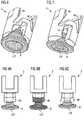
- FIG. 2 shows the distal end of a first embodiment of a piston rod 3.
- the distal end comprises the distal face 11 P as well as a predetermined area of weakness 4A having a hemispherical geometry comprising two bars separated by two openings 15.
- the distal end of the piston rod 3 is designed so that upon applying a force in axial direction, the disk-type part of the piston rod comprising the distal face 11 P is pushed towards the main part of the piston rod and a plastic deformation of the predetermined area of weakness 4A having a hemispherical geometry takes place.
- FIGS. 3A and 3B show the distal end of a second embodiment of a piston rod 3 being similar to the embodiment of FIG. 2 .
- the piston rod 3 comprises a distal face 11 P and a predetermined area of weakness 4A shown in FIG. 3A .
- the piston rod 3 (or more precisely, the predetermined area of weakness 4A) is brought into a state of matter which allows plastic deformation (e.g. by heating, shown in FIG. 3A with a hatching rising rightwards).
- a deformation of the predetermined area of weakness 4A takes place.
- the disk-shaped part of the piston rod comprising the proximal face 11 P is pushed towards the main part of the piston rod 3 upon which the predetermined area of weakness 4A is converted into the plastically deformed area 4B.
- This movement may involve a deformation of the bent parts of the predetermined area of weakness 4A so that the most distal part of the plastically deformed area 4B touches the disk-shaped component of the piston rod 3.
- the step involving the plastic deformation of the piston rod 3 may give rise to an improved mechanical stability of the distal end of the piston rod 3.
- FIGS. 4A and 4B show the distal end of a third embodiment of a piston rod 3.
- the geometry of the piston rod is designed to encourage controlled, axial collapse of the distal end of the piston rod under load, particularly when the predetermined area of weakness 4A is heated.
- the geometry of the piston rod 3 according to this embodiment comprises a plurality of openings 15 having an extension in the direction of the axis 16 (being defined by the line spanned between the proximal end of the piston rod 3 and the distal face 11 P, particularly the center of the distal face 11 P of the piston rod) being much longer than the extension in the direction perpendicular to the axis 16 (resembling a lantern-like shape).
- FIG. 4B shows the situation after applying a force in the direction of the axis 16 (shown by an arrow) on the piston rod 3 being in a state of matter that allows plastic deformation.
- the extension of the openings 15 in the direction perpendicular to the axis 16 is shortened much more than the extension in the direction of the axis 16.
- the piston rod 3 abuts on the bung 6 retained in the cartridge 5, more precisely, the distal face 11 P of the piston rod 3 abuts on the proximal face 12B of the bung 6.
- the deformation of the predetermined area of weakness 4A gives rise to a plastically deformed area 4B having an extension in the direction of the axis 16 shortened with respect to the extension in the direction of the axis 16 of the predetermined area of weakness 4A.
- FIGS. 5A and 5B show the distal end of a fourth embodiment of a piston rod 3 being designed to encourage controlled axial collapse of the piston rod under load.
- the piston rod according to this embodiment comprises a plurality of elements being more easily compressible by applying of a force in the direction of the axis 16 than a piston rod 3 containing no recesses.
- the predetermined area of weakness 4A in FIG. 5A has a bellowed shape.
- the proximal face 12B of the bung 6 abuts on the distal face 11 P of the piston rod 3.
- the piston rod 3 is, for example in a heated and plastically deformable state of matter and the area with bellowed shape is pushed so that the extension of the plastically deformed area 4B in the direction of the axis 16 is shortened compared to the extension of the plastically deformable area 4A of FIG. 5A .
- FIG. 6 shows the distal end of a fifth embodiment of a piston rod 3, the piston rod comprising at least two elements.
- the element arranged at the most distal part of the piston rod 3 comprising the distal face 11 P of the piston rod is constructed to be a bearing 8.
- the piston rod further comprises a predetermined area of weakness 4A.
- FIG. 7 shows the distal end of a sixth embodiment of a piston rod 3, being similar to the embodiment shown in FIG. 6 .
- the distal face 11 P of the piston rod 3 is a part of the bearing 8.
- an inductively heatable element 14 with a ball shape is located between the distal end of the main part of the piston rod 3 (comprising the predetermined area of weakness 4A).
- the inductively heatable element 14 may, for example, be made of a metal and may comprise an inductively heatable material on its surface. However, also an inductively heatable core and a surface made from a heat transporting material are possible.
- FIGS. 8A to 8C show the distal end of a seventh embodiment of a piston rod 3.
- the distal end of the piston rod 3 comprises a bearing 8, the bearing 8 comprising the distal face 11 P of the piston rod 3.
- the most distal part of the main element of the piston rod 3 comprises the predetermined area of weakness 4A.
- the step of selectively heating an area of the piston rod 3 is shown.
- the heated part of the piston rod 3 is designed with a checked pattern.
- the bearing 8 may be made of a metal or even of an inductively heatable material; therefore, the predetermined area of weakness 4A may be heated by inductively heating the bearing 8; otherwise, heating of the predetermined area of weakness 4A, for example by means of a concentrated light source, may also involve heating a bearing 8 being made of a heat transporting material. If, however, the proximal face of the bung (not shown) is sensitive against heat, the lower part of the bearing 8 comprising the distal face 11 P of the piston rod 3 may be made of a material with a low heat conduction.
- FIG. 8C shows the distal end of the piston rod 3 after plastic deformation.
- the distal face 11 P of the piston rod 3 abuts on the proximal face of the bung (not shown) and the main element of the piston rod 3 is pushed towards the bearing 8 having the effect that the predetermined area of weakness 4A is plastically deformed and that the diameter of the predetermined area of weakness 4A (in the direction perpendicular to the axis) is widened; the plastically deformed area 4B results.
Claims (13)
- Verfahren zur Montage einer Medikamenten-Verabreichungsvorrichtung, umfassend ein Gehäuse (2), in dem eine Kolbenstange (3) gehalten wird, und eine Kartusche (5), in der ein Pfropfen (6) gehalten wird und die ein Arzneimittel enthält, wobei das Gehäuse (2) ein distales Ende (11) und ein proximales Ende (12) aufweist, gekennzeichnet durch die folgenden Schritte:A) Bereitstellen einer Komponente, die den Abstand zwischen der proximalen Stirnfläche (12B) des Pfropfens (6) und dem proximalen Ende der Kolbenstange (3) definiert,
vorzugsweise eine plastisch verformbare Kolbenstange (3), wobei wenigstens ein Teil der plastisch verformbaren Kolbenstange aus einem plastisch verformbaren Material gefertigt ist,B) in Eingriff bringen der Kartusche (5) und der einen Abstand definierenden Komponente,C) Anordnen der Kartusche (5) in ihrer distalsten Stellung bezüglich der einen Abstand definierenden Komponente und Bestimmen eines Abstands zwischen der proximalen Stirnfläche (12B) des Pfropfens (6) und dem proximalen Ende der einen Abstand definierenden Komponente,D) Berechnen der Lücke zwischen der proximalen Stirnfläche des Pfropfens (6) und dem distalen Ende der Kolbenstange (3) aus dem in Schritt C) bestimmten Abstand,E) Anpassen der Länge der Kolbenstange (3),
vorzugsweise durch Aufbringen einer Kraft auf die plastisch verformbare Kolbenstange (3), wobei sich wenigstens ein Teil der Kolbenstange (3) in einem Zustand befindet, der eine plastische Verformung gestattet, so dass die Kolbenstange (3) plastisch verformt wird und ein Element der Kolbenstange (3) an den Pfropfen (6) anstößt, und durch Anlegen von Bedingungen, um die plastisch verformte Kolbenstange (3) in eine veränderten Zustand zu bringen, in dem keine weitere plastische Verformung stattfindet, wobei die Bedingungen die Veränderung des physikalischen Aggregatzustands und/oder des chemischen Aggregatzustands wenigstens eines Teils des Materials der Kolbenstange beinhalten,F) Befestigen der Kartusche (5) an dem Gehäuse (2). - Verfahren nach dem vorhergehenden Anspruch, wobei die aufgebrachte Kraft aus einer Bewegung der plastisch verformbaren Kolbenstange (3) in die distale Richtung, oder einer Bewegung einer Komponente, die an der plastisch verformbaren Kolbenstange (3) befestigt ist, in die distale Richtung, oder einer Bewegung der Kartusche (5) in die proximale Richtung, oder einer Bewegung einer Komponente, die an der Kartusche (5) befestigt ist, in die proximale Richtung resultiert.
- Verfahren nach einem der vorhergehenden Ansprüche, wobei die Kolbenstange (3) während der Befestigung der Kartusche (5) an dem Gehäuse (2) plastisch verformt wird.
- Verfahren nach einem der vorhergehenden Ansprüche, wobei vor dem Aufbringen einer Kraft auf die plastisch verformbare Kolbenstange das Material wenigstens eines Teils der Kolbenstange durch Erwärmen in einen plastisch verformbaren Aggregatzustand gebracht wird.
- Verfahren nach einem der vorhergehenden Ansprüche, wobei das plastisch verformbare Material wenigstens eines Teils der plastisch verformbaren Kolbenstange ein thermoplastisches Polymer umfasst oder aus einem thermoplastischen Polymer besteht.
- Verfahren nach einem der vorhergehenden Ansprüche, wobei der geänderte Aggregatzustand der plastisch verformbaren Kolbenstange durch Kühlen oder durch Herbeiführen einer chemischen Reaktion des plastisch verformbaren Materials erhalten wird.
- Verfahren nach einem der drei vorhergehenden Ansprüche, wobei das Material wenigstens eines Teils der plastisch verformbaren Kolbenstange eine induktiv erwärmbare Verbindung umfasst und wobei das Material wenigstens eines Teils der Kolbenstange induktiv erwärmt wird, bevor eine Kraft auf die Kolbenstange aufgebracht wird, um sie in einen plastisch verformbaren Zustand zu bringen.
- Verfahren nach einem der vorhergehenden Ansprüche, wobei die plastisch verformbare Kolbenstange ein erstes Element, welches das plastisch verformbare Material umfasst, und ein zweites Element umfasst, von dem wenigstens ein Teil aus einem induktiv erwärmbaren Material gefertigt ist, wobei das erste Element an das zweite Element anstößt, und wobei vor dem Aufbringen einer Kraft auf die plastisch verformbare Kolbenstange das plastisch verformbare Material induktiv erwärmt wird.
- Verfahren nach Anspruch 1, wobei die einen Abstand definierende Komponente ein Kartuschenhalter (7) ist.
- Kolbenstange (3), die in einer Anordnung für eine Medikamenten-Verabreichungsvorrichtung enthalten ist, mit einem distalen Ende und einem proximalen Ende, die in Richtung einer Achse voneinander beabstandet sind, wobei die Kolbenstange (3) einen vorbestimmten Schwächungsbereich (4A) umfasst, der bei Aufbringen einer Kraft in Richtung der Achse bezüglich der Kolbenstange (3) plastisch verformbar ist und induktiv erwärmbares Material umfasst.
- Anordnung für eine Medikamenten-Verabreichungsvorrichtung mit einem distalen Ende und einem proximalen Ende, umfassend:- ein Gehäuse (2), in dem eine Kolbenstange (3) gehalten wird,- eine Kartusche (5), in der ein Pfropfen (6) gehalten wird,- wobei die Kartusche (5) an dem Gehäuse (2) befestigt ist- und wobei die Kolbenstange (3) an der proximalen Stirnfläche (12B) des Pfropfens (6) anstößt, dadurch gekennzeichnet, dass die Kolbenstange (3) einen plastisch verformten Bereich (4B) umfasst, wobei wenigstens ein Teil der plastisch verformten Kolbenstange (3) aus einem plastisch verformbaren Material erhalten wird, und dass der plastisch verformte Bereich (4B) durch plastische Verformung eines vorbestimmten Schwächebereichs (4A) der Kolbenstange (3) durch Anwendung einer Kraft in Richtung der Achse in Bezug auf die Kolbenstange (3) erhalten wird.
- Anordnung nach einem der vorhergehenden Ansprüche, erhalten durch das Verfahren nach einem der Ansprüche 1 bis 9.
- Medikamenten-Verabreichungsvorrichtung, umfassend die Anordnung nach einem der zwei vorhergehenden Ansprüche.
Priority Applications (1)
| Application Number | Priority Date | Filing Date | Title |
|---|---|---|---|
| EP10757784.3A EP2482872B2 (de) | 2009-09-30 | 2010-09-29 | Verfahren zur Montage einer Arzneimittelabgabevorrichtung, Anordnung für eine Arzneimittelabgabevorrichtung und Pleuelstange für eine Arzneimittelabgabevorrichtung |
Applications Claiming Priority (3)
| Application Number | Priority Date | Filing Date | Title |
|---|---|---|---|
| EP09171757 | 2009-09-30 | ||
| EP10757784.3A EP2482872B2 (de) | 2009-09-30 | 2010-09-29 | Verfahren zur Montage einer Arzneimittelabgabevorrichtung, Anordnung für eine Arzneimittelabgabevorrichtung und Pleuelstange für eine Arzneimittelabgabevorrichtung |
| PCT/EP2010/064419 WO2011039226A1 (en) | 2009-09-30 | 2010-09-29 | Method for assembling a drug delivery device, assembly for a drug delivery device and piston rod for a drug delivery device |
Publications (3)
| Publication Number | Publication Date |
|---|---|
| EP2482872A1 EP2482872A1 (de) | 2012-08-08 |
| EP2482872B1 EP2482872B1 (de) | 2016-05-18 |
| EP2482872B2 true EP2482872B2 (de) | 2019-12-11 |
Family
ID=41692992
Family Applications (1)
| Application Number | Title | Priority Date | Filing Date |
|---|---|---|---|
| EP10757784.3A Active EP2482872B2 (de) | 2009-09-30 | 2010-09-29 | Verfahren zur Montage einer Arzneimittelabgabevorrichtung, Anordnung für eine Arzneimittelabgabevorrichtung und Pleuelstange für eine Arzneimittelabgabevorrichtung |
Country Status (6)
| Country | Link |
|---|---|
| US (1) | US20120283662A1 (de) |
| EP (1) | EP2482872B2 (de) |
| JP (2) | JP2013506458A (de) |
| CA (1) | CA2773844A1 (de) |
| DK (1) | DK2482872T4 (de) |
| WO (1) | WO2011039226A1 (de) |
Families Citing this family (32)
| Publication number | Priority date | Publication date | Assignee | Title |
|---|---|---|---|---|
| EP2292286A1 (de) * | 2009-09-07 | 2011-03-09 | Sanofi-Aventis Deutschland GmbH | Antriebsmechanismus für Arzneimittelabgabevorrichtungen und Arzneimittelabgabevorrichtung |
| US10232122B2 (en) * | 2009-09-07 | 2019-03-19 | Sanofi-Aventis Deutschland Gmbh | Drive mechanism for drug delivery device |
| JP5749724B2 (ja) * | 2009-09-30 | 2015-07-15 | サノフィ−アベンティス・ドイチュラント・ゲゼルシャフト・ミット・ベシュレンクテル・ハフツング | 薬物送達デバイス用アセンブリ |
| TW201127435A (en) * | 2009-09-30 | 2011-08-16 | Sanofi Aventis Deutschland | Drive mechanism for a drug delivery device |
| EP2482896A1 (de) * | 2009-09-30 | 2012-08-08 | Sanofi-Aventis Deutschland GmbH | Treibermechanismus für eine wirkstofffreisetzungsvorrichtung und rücksetzungselement für einen treibermechanismus |
| EP2482879B1 (de) * | 2009-09-30 | 2016-11-09 | Sanofi-Aventis Deutschland GmbH | Verfahren und anordnung für eine arzneimittelabgabevorrichtung |
| DK2482884T3 (en) * | 2009-09-30 | 2016-02-08 | Sanofi Aventis Deutschland | PHARMACEUTICAL FEED DEVICE AND drive section TO A drug delivery device |
| US8939943B2 (en) | 2011-01-26 | 2015-01-27 | Kaleo, Inc. | Medicament delivery device for administration of opioid antagonists including formulations for naloxone |
| US9084849B2 (en) | 2011-01-26 | 2015-07-21 | Kaleo, Inc. | Medicament delivery devices for administration of a medicament within a prefilled syringe |
| US8627816B2 (en) | 2011-02-28 | 2014-01-14 | Intelliject, Inc. | Medicament delivery device for administration of opioid antagonists including formulations for naloxone |
| RU2603289C2 (ru) * | 2011-06-17 | 2016-11-27 | Санофи-Авентис Дойчланд Гмбх | Устройство подачи лекарства для введения заданной дозы медикамента |
| AR088084A1 (es) * | 2011-09-29 | 2014-05-07 | Sanofi Aventis Deutschland | Aparato para administracion de medicamentos y procedimiento de montaje de un aparato para administracion de medicamentos |
| CN103998078B (zh) * | 2011-11-29 | 2016-08-24 | 赛诺菲-安万特德国有限公司 | 药物输送装置的焊接外壳部件 |
| US9522235B2 (en) | 2012-05-22 | 2016-12-20 | Kaleo, Inc. | Devices and methods for delivering medicaments from a multi-chamber container |
| DK2885032T3 (en) * | 2012-08-20 | 2018-05-22 | Sanofi Aventis Deutschland | PHARMACEUTICAL APPLICATION DEVICE AND METHOD FOR DETECTING CONTACT BETWEEN PISTON PISTON AND PATTERN PROTECTOR AT DISTANCE MEASUREMENT |
| EP2752211A1 (de) * | 2013-01-07 | 2014-07-09 | F. Hoffmann-La Roche Ltd. | Sicherheitsvorrichtung für eine Injektionsspritze |
| TW201603850A (zh) * | 2014-07-01 | 2016-02-01 | 賽諾菲公司 | 藥物輸送裝置及其製造方法 |
| US9517307B2 (en) | 2014-07-18 | 2016-12-13 | Kaleo, Inc. | Devices and methods for delivering opioid antagonists including formulations for naloxone |
| AU2016235054B2 (en) | 2015-03-24 | 2020-07-16 | Kaleo, Inc. | Devices and methods for delivering a lyophilized medicament |
| WO2016155975A1 (en) * | 2015-03-27 | 2016-10-06 | Novo Nordisk A/S | Deformable piston washer |
| EP3277345B1 (de) * | 2015-03-31 | 2021-12-08 | Novo Nordisk A/S | Kartuschenhalteranordnung für arzneimittelabgabevorrichtung |
| JP6830067B2 (ja) | 2015-06-30 | 2021-02-17 | カレオ,インコーポレイテッド | プレフィルドシリンジ内の医薬を投与する自動注射器 |
| EP3316944B1 (de) | 2015-07-01 | 2019-09-11 | Novo Nordisk A/S | Verfahren zur montage einer arzneimittelabgabevorrichtung und durch das verfahren geformte arzneimittelabgabevorrichtung |
| EP3368105B1 (de) | 2015-10-30 | 2020-07-01 | Novo Nordisk A/S | Verfahren zur herstellung vorgefüllter arzneimittelabgabevorrichtungen |
| EP3202443A1 (de) | 2016-02-02 | 2017-08-09 | Novo Nordisk A/S | Kolbenunterlegscheibe für arzneimittelabgabevorrichtung, verfahren zur herstellung solch einer kolbenunterlegscheibe und verfahren zum zusammenbau einer arzneimittelabgabevorrichtung |
| AU2017379094B2 (en) | 2016-12-23 | 2023-08-24 | Kaleo, Inc. | Medicament delivery device and methods for delivering drugs to infants and children |
| EP3574032B1 (de) * | 2017-01-30 | 2022-08-31 | Lubrizol Advanced Materials, Inc. | Antimikrobielle thermoplastische polyurethane |
| US20190054250A1 (en) * | 2017-08-17 | 2019-02-21 | Qualcomm Incorporated | Drug delivery measurement in a medicine delivery device |
| CA3145580A1 (en) | 2019-08-09 | 2021-02-18 | Kaleo, Inc. | Devices and methods for delivery of substances within a prefilled syringe |
| EP3808393A1 (de) * | 2019-10-15 | 2021-04-21 | Ypsomed AG | Kartuschenfixierung für eine wirkstoffabgabevorrichtung |
| EP4054680A1 (de) * | 2019-11-08 | 2022-09-14 | SHL Medical AG | Rohrförmiger rotator |
| JP2024510668A (ja) * | 2021-03-25 | 2024-03-08 | アムジエン・インコーポレーテツド | 薬物送達デバイス |
Family Cites Families (28)
| Publication number | Priority date | Publication date | Assignee | Title |
|---|---|---|---|---|
| US2569764A (en) * | 1946-07-25 | 1951-10-02 | Boyd Welsh Inc | Initially soft stiffenable material |
| US3677245A (en) | 1970-04-06 | 1972-07-18 | Becton Dickinson Co | Self-contained disposable syringe |
| US3834387A (en) | 1972-08-10 | 1974-09-10 | Sherwood Medical Ind Inc | Breech loaded syringe with deformable piston |
| NL172403C (nl) | 1974-04-08 | 1983-09-01 | Duphar Int Res | Injectiespuit met een patroon en een patroonhouder, waarbij de patroonhouder voorzien is van vergrendelingsmiddelen voor de patroon, alsmede patroonhouder voor een injectiespuit. |
| NO157085C (no) | 1986-01-07 | 1988-01-20 | Chr Sandsdalen | Anordning ved injeksjonssprte for engangsbruk. |
| FR2622804A1 (fr) | 1987-11-06 | 1989-05-12 | Bonabe De Rouge Claude | Seringue non reutilisable |
| ES1007520Y (es) | 1988-09-09 | 1989-08-16 | Hispano Ico S.A. | Disposicion de inhabilitacion para jeringuillas de un solo uso. |
| US5084017A (en) * | 1989-10-10 | 1992-01-28 | John Maffetone | Self disabling, single use, hypodermic syringe |
| US5085640A (en) * | 1990-04-06 | 1992-02-04 | Gibbs Andrew H | Non-reusable medical needle apparatus |
| US5242416A (en) | 1992-01-09 | 1993-09-07 | Hutson Clifford L | Shield assembly for needle syringes |
| WO1995031235A1 (en) | 1994-05-16 | 1995-11-23 | Washington Biotech Corporation | Modular automatic or manual emergency medicine injection system |
| JP2568394Y2 (ja) * | 1993-07-30 | 1998-04-08 | 沖電気工業株式会社 | 筒状無ねじ筐体のパッケージ保持構造 |
| ATE254939T1 (de) * | 1993-07-31 | 2003-12-15 | Aradigm Corp | Nadelloser injektor |
| US5582595A (en) | 1995-09-28 | 1996-12-10 | Habley Medical Technology Corporation | Aspirating syringe having a plunger guide for a reciprocating plunger assembly |
| JPH09150458A (ja) * | 1995-11-29 | 1997-06-10 | Alps Electric Co Ltd | 樹脂成形部材の接合体および樹脂成形部材の接合方法 |
| US6159184A (en) | 1997-03-10 | 2000-12-12 | Safety Syringes, Inc. | Disposable self-shielding unit dose syringe guard |
| JP4623927B2 (ja) | 2000-06-19 | 2011-02-02 | テルモ株式会社 | シリンジ |
| GB0211294D0 (en) | 2002-05-17 | 2002-06-26 | Owen Mumford Ltd | Improvements relating to injection devices |
| EP1551482B1 (de) * | 2002-10-11 | 2011-12-14 | Becton Dickinson and Company | Spritze zum einmaligen gebrauch mit sicherheitsschutz |
| GB2414775B (en) | 2004-05-28 | 2008-05-21 | Cilag Ag Int | Releasable coupling and injection device |
| US20060173409A1 (en) * | 2004-12-28 | 2006-08-03 | Chang-Ming Yang | Safety syring |
| TWI294782B (en) | 2006-01-27 | 2008-03-21 | Bencha Internat Group Inc | Medically safety injector with a collapsable plunger combination thereof |
| TWI498137B (zh) | 2006-06-30 | 2015-09-01 | Abbvie Biotechnology Ltd | 自動注射裝置 |
| DE102006047537A1 (de) * | 2006-10-07 | 2008-04-10 | Sanofi-Aventis Deutschland Gmbh | Optisches Bestimmen der Stopfenposition in Glasampullen |
| MX2009013639A (es) * | 2007-06-12 | 2010-04-30 | Becton Dickinson Co | Jeringa con mecanismo inhabilitante. |
| US20090105691A1 (en) * | 2007-10-17 | 2009-04-23 | Tyco Healthcare Group Lp | Access port using shape memory anchor |
| US20090137949A1 (en) | 2007-11-26 | 2009-05-28 | Bioject Inc. | Needle-free injection device with nozzle auto-disable |
| BRPI0907110A2 (pt) * | 2008-01-28 | 2019-09-24 | Novo Nordisk As | dispositivo de injeção para realizar injeções médicas |
-
2010
- 2010-09-29 DK DK10757784.3T patent/DK2482872T4/da active
- 2010-09-29 EP EP10757784.3A patent/EP2482872B2/de active Active
- 2010-09-29 JP JP2012531390A patent/JP2013506458A/ja active Pending
- 2010-09-29 WO PCT/EP2010/064419 patent/WO2011039226A1/en active Application Filing
- 2010-09-29 US US13/496,701 patent/US20120283662A1/en not_active Abandoned
- 2010-09-29 CA CA2773844A patent/CA2773844A1/en not_active Abandoned
-
2015
- 2015-01-15 JP JP2015005650A patent/JP2015091397A/ja not_active Ceased
Also Published As
| Publication number | Publication date |
|---|---|
| DK2482872T4 (da) | 2020-03-02 |
| CA2773844A1 (en) | 2011-04-07 |
| JP2015091397A (ja) | 2015-05-14 |
| US20120283662A1 (en) | 2012-11-08 |
| JP2013506458A (ja) | 2013-02-28 |
| WO2011039226A1 (en) | 2011-04-07 |
| EP2482872A1 (de) | 2012-08-08 |
| DK2482872T3 (en) | 2016-08-29 |
| EP2482872B1 (de) | 2016-05-18 |
Similar Documents
| Publication | Publication Date | Title |
|---|---|---|
| EP2482872B2 (de) | Verfahren zur Montage einer Arzneimittelabgabevorrichtung, Anordnung für eine Arzneimittelabgabevorrichtung und Pleuelstange für eine Arzneimittelabgabevorrichtung | |
| EP2552519B1 (de) | Kolbenstangenanordnung für eine wirkstofffreisetzungsvorrichtung | |
| US9402962B2 (en) | Assembly for use in a drug delivery device | |
| EP2493531B2 (de) | Arzneimittelabgabevorrichtungen und Montageverfahren | |
| US8900203B2 (en) | Drug delivery device with clearance compensation means | |
| US20120283660A1 (en) | Method and assembly for a drug delivery device | |
| US8702659B2 (en) | Drug delivery device | |
| CA2773918A1 (en) | Drug delivery device | |
| IL215218A (en) | Arranging assembly and coupling assembly for drug release device | |
| WO2012062909A2 (en) | Assembly for a drug delivery device and piston rod |
Legal Events
| Date | Code | Title | Description |
|---|---|---|---|
| PUAI | Public reference made under article 153(3) epc to a published international application that has entered the european phase |
Free format text: ORIGINAL CODE: 0009012 |
|
| 17P | Request for examination filed |
Effective date: 20120502 |
|
| AK | Designated contracting states |
Kind code of ref document: A1 Designated state(s): AL AT BE BG CH CY CZ DE DK EE ES FI FR GB GR HR HU IE IS IT LI LT LU LV MC MK MT NL NO PL PT RO SE SI SK SM TR |
|
| DAX | Request for extension of the european patent (deleted) | ||
| GRAP | Despatch of communication of intention to grant a patent |
Free format text: ORIGINAL CODE: EPIDOSNIGR1 |
|
| INTG | Intention to grant announced |
Effective date: 20151210 |
|
| GRAS | Grant fee paid |
Free format text: ORIGINAL CODE: EPIDOSNIGR3 |
|
| GRAA | (expected) grant |
Free format text: ORIGINAL CODE: 0009210 |
|
| AK | Designated contracting states |
Kind code of ref document: B1 Designated state(s): AL AT BE BG CH CY CZ DE DK EE ES FI FR GB GR HR HU IE IS IT LI LT LU LV MC MK MT NL NO PL PT RO SE SI SK SM TR |
|
| REG | Reference to a national code |
Ref country code: GB Ref legal event code: FG4D |
|
| REG | Reference to a national code |
Ref country code: CH Ref legal event code: EP |
|
| REG | Reference to a national code |
Ref country code: IE Ref legal event code: FG4D Ref country code: AT Ref legal event code: REF Ref document number: 799867 Country of ref document: AT Kind code of ref document: T Effective date: 20160615 |
|
| REG | Reference to a national code |
Ref country code: DE Ref legal event code: R096 Ref document number: 602010033491 Country of ref document: DE |
|
| REG | Reference to a national code |
Ref country code: FR Ref legal event code: PLFP Year of fee payment: 7 |
|
| REG | Reference to a national code |
Ref country code: DK Ref legal event code: T3 Effective date: 20160828 |
|
| REG | Reference to a national code |
Ref country code: NL Ref legal event code: MP Effective date: 20160518 |
|
| REG | Reference to a national code |
Ref country code: LT Ref legal event code: MG4D |
|
| PG25 | Lapsed in a contracting state [announced via postgrant information from national office to epo] |
Ref country code: LT Free format text: LAPSE BECAUSE OF FAILURE TO SUBMIT A TRANSLATION OF THE DESCRIPTION OR TO PAY THE FEE WITHIN THE PRESCRIBED TIME-LIMIT Effective date: 20160518 Ref country code: NO Free format text: LAPSE BECAUSE OF FAILURE TO SUBMIT A TRANSLATION OF THE DESCRIPTION OR TO PAY THE FEE WITHIN THE PRESCRIBED TIME-LIMIT Effective date: 20160818 Ref country code: FI Free format text: LAPSE BECAUSE OF FAILURE TO SUBMIT A TRANSLATION OF THE DESCRIPTION OR TO PAY THE FEE WITHIN THE PRESCRIBED TIME-LIMIT Effective date: 20160518 Ref country code: NL Free format text: LAPSE BECAUSE OF FAILURE TO SUBMIT A TRANSLATION OF THE DESCRIPTION OR TO PAY THE FEE WITHIN THE PRESCRIBED TIME-LIMIT Effective date: 20160518 |
|
| REG | Reference to a national code |
Ref country code: AT Ref legal event code: MK05 Ref document number: 799867 Country of ref document: AT Kind code of ref document: T Effective date: 20160518 |
|
| PG25 | Lapsed in a contracting state [announced via postgrant information from national office to epo] |
Ref country code: PT Free format text: LAPSE BECAUSE OF FAILURE TO SUBMIT A TRANSLATION OF THE DESCRIPTION OR TO PAY THE FEE WITHIN THE PRESCRIBED TIME-LIMIT Effective date: 20160919 Ref country code: HR Free format text: LAPSE BECAUSE OF FAILURE TO SUBMIT A TRANSLATION OF THE DESCRIPTION OR TO PAY THE FEE WITHIN THE PRESCRIBED TIME-LIMIT Effective date: 20160518 Ref country code: ES Free format text: LAPSE BECAUSE OF FAILURE TO SUBMIT A TRANSLATION OF THE DESCRIPTION OR TO PAY THE FEE WITHIN THE PRESCRIBED TIME-LIMIT Effective date: 20160518 Ref country code: GR Free format text: LAPSE BECAUSE OF FAILURE TO SUBMIT A TRANSLATION OF THE DESCRIPTION OR TO PAY THE FEE WITHIN THE PRESCRIBED TIME-LIMIT Effective date: 20160819 Ref country code: LV Free format text: LAPSE BECAUSE OF FAILURE TO SUBMIT A TRANSLATION OF THE DESCRIPTION OR TO PAY THE FEE WITHIN THE PRESCRIBED TIME-LIMIT Effective date: 20160518 Ref country code: SE Free format text: LAPSE BECAUSE OF FAILURE TO SUBMIT A TRANSLATION OF THE DESCRIPTION OR TO PAY THE FEE WITHIN THE PRESCRIBED TIME-LIMIT Effective date: 20160518 |
|
| PG25 | Lapsed in a contracting state [announced via postgrant information from national office to epo] |
Ref country code: IT Free format text: LAPSE BECAUSE OF FAILURE TO SUBMIT A TRANSLATION OF THE DESCRIPTION OR TO PAY THE FEE WITHIN THE PRESCRIBED TIME-LIMIT Effective date: 20160518 |
|
| PG25 | Lapsed in a contracting state [announced via postgrant information from national office to epo] |
Ref country code: CZ Free format text: LAPSE BECAUSE OF FAILURE TO SUBMIT A TRANSLATION OF THE DESCRIPTION OR TO PAY THE FEE WITHIN THE PRESCRIBED TIME-LIMIT Effective date: 20160518 Ref country code: EE Free format text: LAPSE BECAUSE OF FAILURE TO SUBMIT A TRANSLATION OF THE DESCRIPTION OR TO PAY THE FEE WITHIN THE PRESCRIBED TIME-LIMIT Effective date: 20160518 Ref country code: SK Free format text: LAPSE BECAUSE OF FAILURE TO SUBMIT A TRANSLATION OF THE DESCRIPTION OR TO PAY THE FEE WITHIN THE PRESCRIBED TIME-LIMIT Effective date: 20160518 Ref country code: RO Free format text: LAPSE BECAUSE OF FAILURE TO SUBMIT A TRANSLATION OF THE DESCRIPTION OR TO PAY THE FEE WITHIN THE PRESCRIBED TIME-LIMIT Effective date: 20160518 |
|
| REG | Reference to a national code |
Ref country code: DE Ref legal event code: R026 Ref document number: 602010033491 Country of ref document: DE |
|
| PLBI | Opposition filed |
Free format text: ORIGINAL CODE: 0009260 |
|
| PLBI | Opposition filed |
Free format text: ORIGINAL CODE: 0009260 |
|
| PG25 | Lapsed in a contracting state [announced via postgrant information from national office to epo] |
Ref country code: SM Free format text: LAPSE BECAUSE OF FAILURE TO SUBMIT A TRANSLATION OF THE DESCRIPTION OR TO PAY THE FEE WITHIN THE PRESCRIBED TIME-LIMIT Effective date: 20160518 Ref country code: PL Free format text: LAPSE BECAUSE OF FAILURE TO SUBMIT A TRANSLATION OF THE DESCRIPTION OR TO PAY THE FEE WITHIN THE PRESCRIBED TIME-LIMIT Effective date: 20160518 Ref country code: BE Free format text: LAPSE BECAUSE OF NON-PAYMENT OF DUE FEES Effective date: 20160518 Ref country code: AT Free format text: LAPSE BECAUSE OF FAILURE TO SUBMIT A TRANSLATION OF THE DESCRIPTION OR TO PAY THE FEE WITHIN THE PRESCRIBED TIME-LIMIT Effective date: 20160518 |
|
| 26 | Opposition filed |
Opponent name: WMC MATTHES CONSULTING, WIELAND MATTHES Effective date: 20170207 |
|
| PLAX | Notice of opposition and request to file observation + time limit sent |
Free format text: ORIGINAL CODE: EPIDOSNOBS2 |
|
| 26 | Opposition filed |
Opponent name: CILAG GMBH INTERNATIONAL Effective date: 20170220 |
|
| PG25 | Lapsed in a contracting state [announced via postgrant information from national office to epo] |
Ref country code: MC Free format text: LAPSE BECAUSE OF FAILURE TO SUBMIT A TRANSLATION OF THE DESCRIPTION OR TO PAY THE FEE WITHIN THE PRESCRIBED TIME-LIMIT Effective date: 20160518 |
|
| PG25 | Lapsed in a contracting state [announced via postgrant information from national office to epo] |
Ref country code: SI Free format text: LAPSE BECAUSE OF FAILURE TO SUBMIT A TRANSLATION OF THE DESCRIPTION OR TO PAY THE FEE WITHIN THE PRESCRIBED TIME-LIMIT Effective date: 20160518 |
|
| REG | Reference to a national code |
Ref country code: IE Ref legal event code: MM4A |
|
| PLBB | Reply of patent proprietor to notice(s) of opposition received |
Free format text: ORIGINAL CODE: EPIDOSNOBS3 |
|
| PG25 | Lapsed in a contracting state [announced via postgrant information from national office to epo] |
Ref country code: IE Free format text: LAPSE BECAUSE OF NON-PAYMENT OF DUE FEES Effective date: 20160929 |
|
| REG | Reference to a national code |
Ref country code: FR Ref legal event code: PLFP Year of fee payment: 8 |
|
| PG25 | Lapsed in a contracting state [announced via postgrant information from national office to epo] |
Ref country code: LU Free format text: LAPSE BECAUSE OF NON-PAYMENT OF DUE FEES Effective date: 20160929 |
|
| PG25 | Lapsed in a contracting state [announced via postgrant information from national office to epo] |
Ref country code: CY Free format text: LAPSE BECAUSE OF FAILURE TO SUBMIT A TRANSLATION OF THE DESCRIPTION OR TO PAY THE FEE WITHIN THE PRESCRIBED TIME-LIMIT Effective date: 20160518 Ref country code: HU Free format text: LAPSE BECAUSE OF FAILURE TO SUBMIT A TRANSLATION OF THE DESCRIPTION OR TO PAY THE FEE WITHIN THE PRESCRIBED TIME-LIMIT; INVALID AB INITIO Effective date: 20100929 |
|
| PG25 | Lapsed in a contracting state [announced via postgrant information from national office to epo] |
Ref country code: TR Free format text: LAPSE BECAUSE OF FAILURE TO SUBMIT A TRANSLATION OF THE DESCRIPTION OR TO PAY THE FEE WITHIN THE PRESCRIBED TIME-LIMIT Effective date: 20160518 Ref country code: MK Free format text: LAPSE BECAUSE OF FAILURE TO SUBMIT A TRANSLATION OF THE DESCRIPTION OR TO PAY THE FEE WITHIN THE PRESCRIBED TIME-LIMIT Effective date: 20160518 Ref country code: IS Free format text: LAPSE BECAUSE OF FAILURE TO SUBMIT A TRANSLATION OF THE DESCRIPTION OR TO PAY THE FEE WITHIN THE PRESCRIBED TIME-LIMIT Effective date: 20160518 Ref country code: MT Free format text: LAPSE BECAUSE OF NON-PAYMENT OF DUE FEES Effective date: 20160930 |
|
| PG25 | Lapsed in a contracting state [announced via postgrant information from national office to epo] |
Ref country code: BG Free format text: LAPSE BECAUSE OF FAILURE TO SUBMIT A TRANSLATION OF THE DESCRIPTION OR TO PAY THE FEE WITHIN THE PRESCRIBED TIME-LIMIT Effective date: 20160518 |
|
| REG | Reference to a national code |
Ref country code: FR Ref legal event code: PLFP Year of fee payment: 9 |
|
| PG25 | Lapsed in a contracting state [announced via postgrant information from national office to epo] |
Ref country code: AL Free format text: LAPSE BECAUSE OF FAILURE TO SUBMIT A TRANSLATION OF THE DESCRIPTION OR TO PAY THE FEE WITHIN THE PRESCRIBED TIME-LIMIT Effective date: 20160518 |
|
| REG | Reference to a national code |
Ref country code: CH Ref legal event code: PK Free format text: TITEL |
|
| APBM | Appeal reference recorded |
Free format text: ORIGINAL CODE: EPIDOSNREFNO |
|
| APBP | Date of receipt of notice of appeal recorded |
Free format text: ORIGINAL CODE: EPIDOSNNOA2O |
|
| APAH | Appeal reference modified |
Free format text: ORIGINAL CODE: EPIDOSCREFNO |
|
| APBU | Appeal procedure closed |
Free format text: ORIGINAL CODE: EPIDOSNNOA9O |
|
| PUAH | Patent maintained in amended form |
Free format text: ORIGINAL CODE: 0009272 |
|
| STAA | Information on the status of an ep patent application or granted ep patent |
Free format text: STATUS: PATENT MAINTAINED AS AMENDED |
|
| REG | Reference to a national code |
Ref country code: CH Ref legal event code: AELC |
|
| 27A | Patent maintained in amended form |
Effective date: 20191211 |
|
| AK | Designated contracting states |
Kind code of ref document: B2 Designated state(s): AL AT BE BG CH CY CZ DE DK EE ES FI FR GB GR HR HU IE IS IT LI LT LU LV MC MK MT NL NO PL PT RO SE SI SK SM TR |
|
| REG | Reference to a national code |
Ref country code: DE Ref legal event code: R102 Ref document number: 602010033491 Country of ref document: DE |
|
| REG | Reference to a national code |
Ref country code: DK Ref legal event code: T4 Effective date: 20200225 |
|
| PGFP | Annual fee paid to national office [announced via postgrant information from national office to epo] |
Ref country code: DK Payment date: 20230627 Year of fee payment: 14 |
|
| PGFP | Annual fee paid to national office [announced via postgrant information from national office to epo] |
Ref country code: GB Payment date: 20230810 Year of fee payment: 14 |
|
| PGFP | Annual fee paid to national office [announced via postgrant information from national office to epo] |
Ref country code: FR Payment date: 20230808 Year of fee payment: 14 Ref country code: DE Payment date: 20230802 Year of fee payment: 14 |
|
| PGFP | Annual fee paid to national office [announced via postgrant information from national office to epo] |
Ref country code: CH Payment date: 20231001 Year of fee payment: 14 |