EP2292286A1 - Antriebsmechanismus für Arzneimittelabgabevorrichtungen und Arzneimittelabgabevorrichtung - Google Patents
Antriebsmechanismus für Arzneimittelabgabevorrichtungen und Arzneimittelabgabevorrichtung Download PDFInfo
- Publication number
- EP2292286A1 EP2292286A1 EP09011420A EP09011420A EP2292286A1 EP 2292286 A1 EP2292286 A1 EP 2292286A1 EP 09011420 A EP09011420 A EP 09011420A EP 09011420 A EP09011420 A EP 09011420A EP 2292286 A1 EP2292286 A1 EP 2292286A1
- Authority
- EP
- European Patent Office
- Prior art keywords
- piston rod
- drive
- distal end
- sleeve
- drive mechanism
- Prior art date
- Legal status (The legal status is an assumption and is not a legal conclusion. Google has not performed a legal analysis and makes no representation as to the accuracy of the status listed.)
- Ceased
Links
Images

Classifications
-
- A—HUMAN NECESSITIES
- A61—MEDICAL OR VETERINARY SCIENCE; HYGIENE
- A61M—DEVICES FOR INTRODUCING MEDIA INTO, OR ONTO, THE BODY; DEVICES FOR TRANSDUCING BODY MEDIA OR FOR TAKING MEDIA FROM THE BODY; DEVICES FOR PRODUCING OR ENDING SLEEP OR STUPOR
- A61M5/00—Devices for bringing media into the body in a subcutaneous, intra-vascular or intramuscular way; Accessories therefor, e.g. filling or cleaning devices, arm-rests
- A61M5/178—Syringes
- A61M5/31—Details
- A61M5/315—Pistons; Piston-rods; Guiding, blocking or restricting the movement of the rod or piston; Appliances on the rod for facilitating dosing ; Dosing mechanisms
- A61M5/31565—Administration mechanisms, i.e. constructional features, modes of administering a dose
- A61M5/3159—Dose expelling manners
- A61M5/31593—Multi-dose, i.e. individually set dose repeatedly administered from the same medicament reservoir
-
- A—HUMAN NECESSITIES
- A61—MEDICAL OR VETERINARY SCIENCE; HYGIENE
- A61M—DEVICES FOR INTRODUCING MEDIA INTO, OR ONTO, THE BODY; DEVICES FOR TRANSDUCING BODY MEDIA OR FOR TAKING MEDIA FROM THE BODY; DEVICES FOR PRODUCING OR ENDING SLEEP OR STUPOR
- A61M5/00—Devices for bringing media into the body in a subcutaneous, intra-vascular or intramuscular way; Accessories therefor, e.g. filling or cleaning devices, arm-rests
- A61M5/178—Syringes
- A61M5/31—Details
- A61M5/315—Pistons; Piston-rods; Guiding, blocking or restricting the movement of the rod or piston; Appliances on the rod for facilitating dosing ; Dosing mechanisms
- A61M5/31533—Dosing mechanisms, i.e. setting a dose
- A61M5/31545—Setting modes for dosing
- A61M5/31548—Mechanically operated dose setting member
- A61M5/3155—Mechanically operated dose setting member by rotational movement of dose setting member, e.g. during setting or filling of a syringe
- A61M5/31551—Mechanically operated dose setting member by rotational movement of dose setting member, e.g. during setting or filling of a syringe including axial movement of dose setting member
-
- A—HUMAN NECESSITIES
- A61—MEDICAL OR VETERINARY SCIENCE; HYGIENE
- A61M—DEVICES FOR INTRODUCING MEDIA INTO, OR ONTO, THE BODY; DEVICES FOR TRANSDUCING BODY MEDIA OR FOR TAKING MEDIA FROM THE BODY; DEVICES FOR PRODUCING OR ENDING SLEEP OR STUPOR
- A61M5/00—Devices for bringing media into the body in a subcutaneous, intra-vascular or intramuscular way; Accessories therefor, e.g. filling or cleaning devices, arm-rests
- A61M5/178—Syringes
- A61M5/31—Details
- A61M5/315—Pistons; Piston-rods; Guiding, blocking or restricting the movement of the rod or piston; Appliances on the rod for facilitating dosing ; Dosing mechanisms
- A61M5/31565—Administration mechanisms, i.e. constructional features, modes of administering a dose
- A61M5/31576—Constructional features or modes of drive mechanisms for piston rods
- A61M5/31583—Constructional features or modes of drive mechanisms for piston rods based on rotational translation, i.e. movement of piston rod is caused by relative rotation between the user activated actuator and the piston rod
- A61M5/31585—Constructional features or modes of drive mechanisms for piston rods based on rotational translation, i.e. movement of piston rod is caused by relative rotation between the user activated actuator and the piston rod performed by axially moving actuator, e.g. an injection button
-
- A—HUMAN NECESSITIES
- A61—MEDICAL OR VETERINARY SCIENCE; HYGIENE
- A61M—DEVICES FOR INTRODUCING MEDIA INTO, OR ONTO, THE BODY; DEVICES FOR TRANSDUCING BODY MEDIA OR FOR TAKING MEDIA FROM THE BODY; DEVICES FOR PRODUCING OR ENDING SLEEP OR STUPOR
- A61M5/00—Devices for bringing media into the body in a subcutaneous, intra-vascular or intramuscular way; Accessories therefor, e.g. filling or cleaning devices, arm-rests
- A61M5/178—Syringes
- A61M5/24—Ampoule syringes, i.e. syringes with needle for use in combination with replaceable ampoules or carpules, e.g. automatic
Definitions
- the present invention relates to a drive mechanism for a medication delivery device and a medication delivery device incorporating such a drive mechanism.
- Portable medication delivery devices are generally known for the administration of a medicinal fluid or drug that is suitable for the self-administration by a patient.
- a drug injection device is especially useful in the shape of a pen, which can be handled easily and kept everywhere available.
- a sophisticated type of drug delivery device is constructed to be refillable and reusable many times.
- a dose of a drug is delivered by means of a drive mechanism, which also allows to set the amount of fluid to be thus injected.
- the drive mechanism comprises rotatable elements, which are rotated relatively to one another around a common axis and are coupled by a gear that is arranged between opposite faces of the rotatable elements.
- the gear comprises a modified ratchet formed by sequences of corresponding ramps sloping in azimuthal direction along the rims of the opposite faces of the rotatable elements. The slope of each ramp is followed by a steep flank, thus rendering a sawtooth shape of the gear, which is apparent when the rotatable elements are viewed during rotation in a radial direction towards the axis.
- the drive mechanism for a medication delivery device is arranged in a body or housing that has a proximal end and a distal end.
- a piston rod which is to be driven by the drive mechanism, is arranged within the body along an axis of rotation.
- a drive member is arranged within the body and is rotationally coupled with the piston rod with respect to the axis of rotation.
- the piston rod is helically movable with respect to the body, the movement comprising a rotation around the axis and a simultaneous shift along the axis.
- the piston rod is provided with a guide track comprising a helical element and an axial element.
- a guide element is arranged within the body and is fixed relatively to the body. The guide element is coupled to the guide track of the piston rod.
- the guide element When the guide element is coupled to the helical element, the guide element guides the helical movement of the piston rod, and when the guide element is coupled to the axial element, it guides an axial movement of the piston rod in the direction to the distal end of the body, the axial movement preceding the helical movement.
- the body can be designed to house, fix or protect components of a medication delivery device (particularly the drive mechanism and the piston rod), preferably by limiting the exposure to contaminants such as liquids, dust or dirt.
- the body can be unitary or a multipart component of tubular or non-tubular shape.
- distal end refers to a part of the body which is intended to be arranged at a portion of the medication delivery device from which a medication is dispensed.
- proximal end refers to a part of the body which is remote from the distal end.
- piston rod encompasses any element that is provided to transfer a movement to the piston, especially for the purpose of dispensing a drug or medicament.
- the piston rod may be flexible or not. It may be of unitary or multipart construction, and may especially be a simple rod, a lead-screw, a rack-and-pinion, a worm gear system, or the like.
- the piston rod has a distal end, which is nearest to the distal end of the body and engages a piston or a bearing that is arranged between the piston and the piston rod to reduce damages that may be caused by friction.
- the piston is provided to expel a medicament from a reservoir or an ampoule.
- the helical element of the piston rod is a screw thread, and the helical movement of the piston rod is caused by the screw thread.
- the guide element which is fixed with respect to the body, slides along the screw thread of the piston rod and thus guides the helical movement of the piston rod.
- the guide element can be a lug or spike sticking out from an inner wall of the body, for example.
- the axial element of the piston rod is an axial groove leading into the screw thread.
- the rotation of the piston rod is effected by a drive member, which is rotationally coupled with the piston rod by means of an axial groove or track of the piston rod, the axial groove having a limit in the direction of the distal end.
- the drive member is arranged in such a manner that it can be shifted towards the distal end.
- the drive member is coupled with the piston rod by means of an axial thread engaging the axial groove of the piston rod.
- the drive member shifts the piston rod towards the distal end when the drive member is shifted towards the distal end while the axial thread is in contact with the limit of the axial groove and the guide element is coupled to the axial element of the piston rod.
- the piston rod can be provided to be shifted towards the distal end by the drive member in a priming step.
- the axial groove intersects the screw thread and allows an axial movement of the piston rod with respect to the drive member.
- the axial groove ends at a first distance from the distal end of the piston rod.
- the screw thread of the piston rod likewise ends at a second distance from the distal end of the piston rod and leads into a further axial groove, which extends to the distal end of the piston rod.
- the first distance is larger than the second distance, so that the further axial groove is shorter than the first distance between the end of the piston rod and the end of the axial groove provided for rotating the piston rod.
- the further axial groove enables an axial movement of the piston rod without rotation as long as the piston rod is near a position in which it is closest to the proximal end of the body.
- An axial shift of the piston rod from this position towards the distal end of the body takes place without rotation of the piston rod until the guide element of the body has completely passed the further axial groove and engages the screw thread of the piston rod. Then the helical movement of the piston rod with respect to the body commences.
- the distal limit of the axial groove that is coupled with the drive member is used to shift the piston rod towards the distal end of the body.
- the guide element to attain the beginning of the screw thread of the piston rod and thus the piston rod to occupy a well-defined position with respect to the body and with respect to a receptacle in the body containing the drug or medicament to be delivered.
- the first dose is therefore delivered precisely as it was set, because an accidental movement of the piston is prevented by the exact initial positioning of the piston rod.
- a dose member is provided to set each dose that is to be delivered, and the priming of the piston rod is performed by pushing the dose member towards the distal end of the body.
- the dose member can be a dose sleeve, which is coupled with the piston rod in such a manner as to allow the piston rod to be shifted towards the distal end by means of the dose sleeve.
- the piston rod is shifted towards the distal end by means of the dose member while the guide element is coupled to the axial element of the piston rod.
- the piston rod can be provided to be shifted towards the distal end by the dose member in a priming step.
- a stop member is arranged within the body and rotationally coupled with the body. This means that a rotation of the stop member with respect to the body is inhibited.
- a spring is arranged within the body, the spring exerting a force on the stop member in the direction to the proximal end.
- a drive member is arranged within the body on the side of the stop member facing the proximal end. The drive member is rotationally coupled with the piston rod and movable relatively to the piston rod along the axis.
- a drive sleeve is arranged within the body on the side of the drive member facing the proximal end. The drive sleeve is rotatable with respect to the body around the axis.
- a gear couples the drive member and the stop member rotationally when the drive sleeve is rotated in a first sense of rotation around the axis.
- a further gear couples the drive member and the drive sleeve rotationally when the drive sleeve is rotated in a second sense of rotation, which is opposite to the first sense of rotation, around the axis.
- a dose sleeve is arranged within the body and is helically movable with respect to the body, the movement comprising a rotation around the axis and a simultaneous shift along the axis. The dose sleeve and the drive sleeve are coupled, the coupling producing a rotation of the drive sleeve in the second sense of rotation around the axis when the dose sleeve is moved towards the distal end.
- a further embodiment of the drive mechanism comprises a means guiding the piston rod in such a manner that the helical movement of the piston rod advances the piston rod towards the distal end when the piston rod is rotated in the second sense of rotation with respect to the body.
- a piston movable by the piston rod, can be arranged in a receptacle at the distal end within the body.
- the receptacle may especially be provided for a cartridge, and the piston may be inserted in the cartridge.
- a dose is set by a movement of the dose sleeve in the direction to the proximal end, and a medication is delivered by a movement of the dose sleeve in the direction to the distal end.
- the drive mechanism it is part of a medication delivery device.
- the body can have the shape of an injection pen, for instance.
- the medication delivery device comprises a receptacle at the distal end within the body and a piston within the receptacle, the piston being movable along the axis by means of the piston rod.
- the receptacle can be provided for a cartridge and the piston can be inserted in the cartridge.
- a dose is set by a movement of a dose sleeve in the direction to the proximal end, and a medication is delivered by a movement of the dose sleeve in the direction to the distal end.
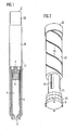
- Fig. 1 shows a schematic cross-section of a medication delivery device in the shape of an injection pen.
- the medication delivery device can have other suitable shapes instead.
- the device comprises a housing or body 1.
- body encompasses any exterior housing, like a main housing or shell, as well as an interior housing, like an insert or inner body arranged within an exterior housing.
- the body 1 is of elongated shape. It has a proximal end 2 and a distal end 3.
- the body 1 can be composed of at least two attachable and separable parts enabling a refill of the device.
- the body 1 comprises a receptacle 4 provided for a drug or medicament.
- the receptacle 4 can be designed to be filled by means of a cartridge 5 containing the drug and being inserted in the receptacle 4. When the cartridge 5 is empty, it can be removed and substituted with a new cartridge.
- the drug is dispensed through an opening of the receptacle by means of a piston 6, which is advanced in the receptacle, particularly within the cartridge 5, towards the distal end 3 by means of a piston rod 7 to expel the drug.
- the distal end 3 can be provided with a needle, not shown in Fig. 1 , or with a needle unit, for instance. If the piston rod 7 is to be moved relatively to the piston 6, a bearing, not shown in Fig. 1 , can be arranged between the piston 6 and the piston rod 7 to reduce damages that may be caused by friction.
- Fig. 1 indicates the location 29 of a drive mechanism, which may be operated by a dose button 20 at the proximal end 2.
- the drug or medicament used in conjunction with the device shown in Fig. 1 is preferably a liquid medication.
- a full cartridge 5 preferably contains a plurality of doses of the medication, which can be insulin, heparin, or growth hormones, for example.
- the device may be disposable or reusable, and it may be configured to dispense fixed doses of the medication or variable doses.
- the drug may be administered by a needle, or the device may be needle-free.
- Fig. 2 shows a perspective view of a part of an embodiment of the drive mechanism.
- a stop member 9, a drive member 10 and a drive sleeve 11 are engaged by a ratchet coupling the drive member 10 and the stop member 9 and by a ratchet coupling the drive member 10 and the drive sleeve 11.
- the ratchets and their function will be described in more detail below.
- the drive sleeve 11 is arranged within a dose sleeve 12, which is provided with a screw thread 15.
- the drive sleeve 11 and the dose sleeve 12 are rotationally coupled, which may be effected by an axial groove 16 of the drive sleeve 11, for example.
- the drive sleeve 11 can be moved axially with respect to the dose sleeve 12, but not rotated with respect to the dose sleeve 12.
- the dose sleeve 12 is provided with the dose button 20.
- the dose sleeve 12 is movable with respect to the body 1.
- a movement of the dose sleeve 12 in the proximal direction sets a dose of the medication which is to be delivered and a movement of the dose sleeve 12 in the distal direction effects a delivery of the set dose.
- the dose sleeve 12 is guided by the screw thread 15 on a helical movement with respect to the body 1, which can be provided with a corresponding thread.
- the thread engaging the thread 15 of the dose sleeve 12 can instead be provided on a further component that is fixed with respect to the body 1.
- Proximal and distal end positions of the movement of the dose sleeve 12 may be determined by respective stop features provided at the body 1.
- the drive member 10 is rotatable with respect to the body 1 and configured to transfer a rotation to the piston rod 7.
- the drive member 10 engages the piston rod 7 by means of a rotational coupling.
- the stop member 9 is rotationally coupled to the body 1. This is explained in more detail below.
- the dose sleeve 12 and, because of the rotational coupling, the drive sleeve 11 are rotated with respect to the body 1 in a first sense of rotation.
- a rotation of the drive member 10 with respect to the body 1 in the first sense of rotation is inhibited by the gear between the drive member 10 and the stop member 9, because this gear rotationally couples the stop member 9 and the drive member 10 in the first sense of rotation.
- the gear between the drive member 10 and the drive sleeve 11 rotationally couples the drive member 10 and the drive sleeve 11, so that the drive member 10 is rotated in the same sense of rotation and with the same angular velocity as the drive sleeve 11.
- this second sense of rotation which is to take place during a delivery of the medicament, the rotation is therefore transferred from the drive member 10 to the piston rod 7.
- Fig. 3 shows the gears between the stop member 9, the drive member 10 and the drive sleeve 11.
- the drive sleeve 11 is coupled to the drive member 10 by a uni-directional gear, which permits a rotation of the drive sleeve 11 with respect to the drive member 10 when the drive sleeve 11 rotates in the first sense of rotation with respect to the body 1.
- the gear prevents a rotation of the drive sleeve 11 with respect to the drive member 10, when the drive sleeve 11 rotates in the second sense of rotation with respect to the body 1.
- the drive member 10 thus follows a rotation of the drive sleeve 11 in the second sense of rotation during a delivery of a medicament.
- the gears form a kind of ratchet.
- the drive member 10 comprises teeth disposed azimuthally along the perimeter of the components and forming a kind of ratchet 21 coupling the drive member 10 and the stop member 9 and a kind of ratchet 22 coupling the drive member 10 and the drive sleeve 11.
- Ramps 23 of the ratchet 21 coupling the drive member 10 and the stop member 9 and ramps 24 of the ratchet 22 coupling the drive member 10 and the drive sleeve 11 are arranged in such a fashion that a relative rotation of those two components that abut at one of the gears is possible in one sense of rotation while the relative rotation of the two components is inhibited in the opposite sense of rotation.
- the stop member 9 can be provided with protruding parts like the teeth 28 shown in Fig. 3 to allow a rotational coupling of the stop member 9 with the body 1. If the teeth 28 are guided in axial grooves in the body 1, the stop member 9 can be moved axially, but not rotated with respect to the body 1.
- the drive member 10 therefore does not rotate, and during a delivery of a dose the drive member 10 rotates to generate a simultaneous rotation of the piston rod 7 according to the further mechanism that will be described in conjunction with Figs. 7 and 8 .
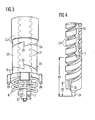
- Fig. 4 shows a perspective view of a portion of the piston rod 7 including its distal end 19.
- the piston rod 7 comprises a screw thread 13 and an axial groove 17 intersecting the screw thread 13 in the longitudinal direction of the piston rod 7.
- the screw thread 13 is thus periodically interrupted within each turn of the screw thread 13, its function to guide the helical movement of the piston rod 7, when it approaches the distal end 3 of the body 1 during the delivery of the medicament, is not inhibited by the axial groove 17.
- Fig. 4 clearly shows that the axial groove 17 ends at a first distance d1 from the distal end 19 of the piston rod 7.
- the axial groove 17 thus enables a protruding element of the drive member 10 to couple the drive member 10 rotationally with the piston rod 7, at the same time allowing an axial movement of the drive member 10 with respect to the piston rod 7.
- the axial movement of the drive member 10 with respect to the piston rod 7 is stopped when the protruding element of the drive member 10 hits the stop at the end of the axial groove 17. If the axial movement of the drive member 10 with respect to the body 1 is continued by the operation of the mechanism, the drive member 10 shifts the piston rod 7 in the direction to the distal end 3 of the body 1.
- a guide element of the body 1 that is provided to slide in the screw thread 13 of the piston rod 7 to generate its helical movement with respect to the body 1 does not generate a rotation of the piston rod 7 with respect to the body 1 as long as the guide element stays in the further axial groove 18.
- the piston rod 7 can therefore be moved axially without rotation towards the distal end 3 of the body 1 until the guide element hits the first turn of the screw thread 13 at a second distance d2 from the distal end 19 of the piston rod 7. At this position the axial movement of the piston rod 7 is stopped, and the helical movement of the piston rod 7 commences when the piston rod 7 is rotated by means of the drive member 10.
- Fig. 5 shows an enlarged perspective view onto the distal end 19 of the piston rod 7. It shows how the further axial groove 18 leads into the screw thread 13.
- Fig. 6 shows a schematic cross-section of a further embodiment of the drive mechanism.
- the dose member 12 is directly used to shift the piston rod 7 towards the distal end 3 during the priming step by means of a spring 30 exerting a force onto the piston rod 7 in the direction of the arrow.
- An internal interface 14 of the body 1 is used to guide the piston rod 7 and to generate its helical movement. This is effected by a guiding element 25 of the internal interface 14.
- the guiding element slides in the screw thread 13 of the piston rod 7. Only the first turn of the screw thread 13 is shown in the schematic cross-section of Fig. 6 .
- the further axial groove 18 is indicated by the broken line of its hidden contour.
- piston rod 7 can be shifted in the direction of the arrow without rotation until the guide element 25 reaches the first turn of the screw thread 13 and the priming step is complete.
- the further movement of the piston rod 7 is helical with respect to the body 1 and is generated by a rotation of the piston rod 7.
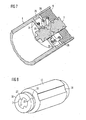
- Fig. 7 shows a cross-section of a part of an embodiment of the drive mechanism having means for guiding the piston rod 7 in a helical movement with respect to the body 1.
- the drive mechanism comprises a spring 8.
- the spring 8 is provided to maintain the stop member 9 in contact with drive member 10 during an operation of the drive mechanism.
- Fig. 7 shows a possible arrangement of the spring 8 between the stop member 9 and a support member, which is an internal interface 14 of the body 1 in the embodiment shown in Fig. 7 .
- the internal interface 14 can be provided with an opening having a guide element 25, by which the piston rod 7 is guided.
- the piston rod 7 is provided with a screw thread 13, which generates a helical movement of the piston rod 7 with respect to the body 1, when the piston rod 7 is moved through the opening of the internal interface 14 and the guiding element 25 slides through the screw thread 13.
- the stop member 9 is shown to have teeth 28, which are guided within axial guides 26 formed in an inner wall of the body 1. This is an example of a rotational coupling between the stop member 9 and the body 1, which enables an axial relative movement.
- the spring 8 If the stop member 9 is shifted in the direction of the distal end, the spring 8 is compressed. The spring force drives the stop member 9 towards the proximal end, so that the stop member 9 is practically permanently in contact with the adjacent drive member 10, which stays in contact with the drive sleeve 11.
- the spring 8 thus allows for a certain relative axial movement of the stop member 9, the drive member 10 and the drive sleeve 11 to facilitate relative rotations involving a sliding motion along the ramps 23,24.
- Fig. 8 shows how the piston rod 7 may be rotationally coupled to the drive member 10.
- the piston rod 7 comprises at least one axial groove 17 or engagement track cutting the screw thread of the piston rod 7 in the axial direction, as can be seen from Fig. 3 .
- Fig. 8 also shows the ratchet 22 coupling the drive member 16 and the drive sleeve 11.
- the drive sleeve 11 is provided with the axial groove 16 also shown in Fig. 2 .
- the drive sleeve 11 may instead be provided with a screw thread, for example.
Priority Applications (11)
| Application Number | Priority Date | Filing Date | Title |
|---|---|---|---|
| EP09011420A EP2292286A1 (de) | 2009-09-07 | 2009-09-07 | Antriebsmechanismus für Arzneimittelabgabevorrichtungen und Arzneimittelabgabevorrichtung |
| CA2773248A CA2773248A1 (en) | 2009-09-07 | 2010-09-03 | Drive mechanism for a medication delivery device and medication delivery device |
| EP10749649.9A EP2475410B1 (de) | 2009-09-07 | 2010-09-03 | Antriebsmechanismus für arzneimittelabgabevorrichtungen und arzneimittelabgabevorrichtung |
| BR112012005089A BR112012005089A2 (pt) | 2009-09-07 | 2010-09-03 | mecanismo de acionamento para um dispositivo de entrega de medicação e dispositivo de entrega de medicação |
| PCT/EP2010/062924 WO2011026928A1 (en) | 2009-09-07 | 2010-09-03 | Drive mechanism for a medication delivery device and medication delivery device |
| US13/393,331 US9802004B2 (en) | 2009-09-07 | 2010-09-03 | Drive mechanism for a medication delivery device and medication delivery device |
| CN201080051719.8A CN102596292B (zh) | 2009-09-07 | 2010-09-03 | 用于输药装置的驱动机构和输药装置 |
| JP2012527332A JP5851402B2 (ja) | 2009-09-07 | 2010-09-03 | 薬物送達デバイス用の駆動機構及び薬物送達デバイス |
| DK10749649.9T DK2475410T3 (da) | 2009-09-07 | 2010-09-03 | Drivmekanisme til medikamentadministrationsanordning og medikamentadministrationsanordning |
| AU2010291223A AU2010291223B2 (en) | 2009-09-07 | 2010-09-03 | Drive mechanism for a medication delivery device and medication delivery device |
| IL218373A IL218373A0 (en) | 2009-09-07 | 2012-02-28 | Drive mechanism for a medication delivery device and medication delivery device |
Applications Claiming Priority (1)
| Application Number | Priority Date | Filing Date | Title |
|---|---|---|---|
| EP09011420A EP2292286A1 (de) | 2009-09-07 | 2009-09-07 | Antriebsmechanismus für Arzneimittelabgabevorrichtungen und Arzneimittelabgabevorrichtung |
Publications (1)
| Publication Number | Publication Date |
|---|---|
| EP2292286A1 true EP2292286A1 (de) | 2011-03-09 |
Family
ID=41571393
Family Applications (2)
| Application Number | Title | Priority Date | Filing Date |
|---|---|---|---|
| EP09011420A Ceased EP2292286A1 (de) | 2009-09-07 | 2009-09-07 | Antriebsmechanismus für Arzneimittelabgabevorrichtungen und Arzneimittelabgabevorrichtung |
| EP10749649.9A Active EP2475410B1 (de) | 2009-09-07 | 2010-09-03 | Antriebsmechanismus für arzneimittelabgabevorrichtungen und arzneimittelabgabevorrichtung |
Family Applications After (1)
| Application Number | Title | Priority Date | Filing Date |
|---|---|---|---|
| EP10749649.9A Active EP2475410B1 (de) | 2009-09-07 | 2010-09-03 | Antriebsmechanismus für arzneimittelabgabevorrichtungen und arzneimittelabgabevorrichtung |
Country Status (10)
| Country | Link |
|---|---|
| US (1) | US9802004B2 (de) |
| EP (2) | EP2292286A1 (de) |
| JP (1) | JP5851402B2 (de) |
| CN (1) | CN102596292B (de) |
| AU (1) | AU2010291223B2 (de) |
| BR (1) | BR112012005089A2 (de) |
| CA (1) | CA2773248A1 (de) |
| DK (1) | DK2475410T3 (de) |
| IL (1) | IL218373A0 (de) |
| WO (1) | WO2011026928A1 (de) |
Cited By (4)
| Publication number | Priority date | Publication date | Assignee | Title |
|---|---|---|---|---|
| WO2011069935A3 (en) * | 2009-12-07 | 2011-08-11 | Sanofi-Aventis Deutschland Gmbh | Drive assembly for a drug delivery device and drug delivery device |
| CN109069752A (zh) * | 2015-12-14 | 2018-12-21 | 赛诺菲-安万特德国有限公司 | 用于注射装置的驱动机构 |
| US10967129B2 (en) | 2015-12-14 | 2021-04-06 | Hoffmann-La Roche Inc. | Dosing device |
| US11433186B2 (en) | 2017-12-13 | 2022-09-06 | Regeneron Pharmaceuticals, Inc. | Devices and methods for precision dose delivery |
Families Citing this family (14)
| Publication number | Priority date | Publication date | Assignee | Title |
|---|---|---|---|---|
| US8177749B2 (en) | 2008-05-20 | 2012-05-15 | Avant Medical Corp. | Cassette for a hidden injection needle |
| CA2724641C (en) | 2008-05-20 | 2020-03-24 | Avant Medical Corp. | Autoinjector system |
| US8052645B2 (en) | 2008-07-23 | 2011-11-08 | Avant Medical Corp. | System and method for an injection using a syringe needle |
| JP5752693B2 (ja) * | 2009-09-30 | 2015-07-22 | サノフィ−アベンティス・ドイチュラント・ゲゼルシャフト・ミット・ベシュレンクテル・ハフツング | 薬物送達デバイス用のアセンブリ及びピストンロッド |
| GB0918145D0 (en) | 2009-10-16 | 2009-12-02 | Owen Mumford Ltd | Injector apparatus |
| WO2012050511A1 (en) * | 2010-10-11 | 2012-04-19 | Shl Group Ab | Medicament delivery device |
| LT2699293T (lt) | 2011-04-20 | 2019-04-25 | Amgen Inc. | Automatinio purškimo prietaisas |
| RU2603289C2 (ru) * | 2011-06-17 | 2016-11-27 | Санофи-Авентис Дойчланд Гмбх | Устройство подачи лекарства для введения заданной дозы медикамента |
| USD898908S1 (en) | 2012-04-20 | 2020-10-13 | Amgen Inc. | Pharmaceutical product cassette for an injection device |
| US10492990B2 (en) | 2013-03-15 | 2019-12-03 | Amgen Inc. | Drug cassette, autoinjector, and autoinjector system |
| JP6336564B2 (ja) | 2013-03-15 | 2018-06-06 | アムゲン・インコーポレーテッド | 薬物カセット、自動注入器、および自動注入器システム |
| CH707217A2 (de) | 2014-02-26 | 2014-04-30 | Tecpharma Licensing Ag | Injektionsvorrichtung zur Verabreichung eines fluiden Produkts. |
| EP3181171A1 (de) | 2015-12-14 | 2017-06-21 | Sanofi-Aventis Deutschland GmbH | Antriebsmechanismus für eine injektionsvorrichtung |
| JP7303289B2 (ja) * | 2018-08-15 | 2023-07-04 | サノフイ | 注射デバイスに取り付けるためのデータ収集装置 |
Citations (6)
| Publication number | Priority date | Publication date | Assignee | Title |
|---|---|---|---|---|
| US3790048A (en) * | 1972-07-28 | 1974-02-05 | Ortho Pharma Corp | Incremental dose dispenser |
| WO1999038554A1 (en) * | 1998-01-30 | 1999-08-05 | Novo Nordisk A/S | An injection syringe |
| WO2004016307A1 (de) * | 2002-08-14 | 2004-02-26 | Tecpharma Licensing Ag | Injektionsvorrichtung mit einer klickgeräuschproduzierenden dosiereinheit |
| WO2004078242A2 (en) * | 2003-03-03 | 2004-09-16 | Dca Design International Ltd. | Improvements in and relating to a pen-type injector |
| US20040210199A1 (en) * | 2001-05-16 | 2004-10-21 | Atterbury William Goodwin | Medication injector apparatus with drive assembly that facilitates reset |
| DE102007052013A1 (de) * | 2007-10-31 | 2009-05-07 | Tecpharma Licensing Ag | Dosiersystem für eine Injektionsvorrichtung und Injektionsvorrichtung |
Family Cites Families (64)
| Publication number | Priority date | Publication date | Assignee | Title |
|---|---|---|---|---|
| US533575A (en) | 1895-02-05 | wilkens | ||
| CH675078A5 (de) * | 1988-01-22 | 1990-08-31 | Nosta Ag | |
| US4973318A (en) * | 1988-02-10 | 1990-11-27 | D.C.P. Af 1988 A/S | Disposable syringe |
| US5226895A (en) | 1989-06-05 | 1993-07-13 | Eli Lilly And Company | Multiple dose injection pen |
| GB9007113D0 (en) | 1990-03-29 | 1990-05-30 | Sams Bernard | Dispensing device |
| ES2074771T3 (es) | 1991-07-24 | 1995-09-16 | Medico Dev Investment Co | Inyector. |
| DK175491D0 (da) | 1991-10-18 | 1991-10-18 | Novo Nordisk As | Apparat |
| US5279586A (en) | 1992-02-04 | 1994-01-18 | Becton, Dickinson And Company | Reusable medication delivery pen |
| US5545147A (en) * | 1992-10-20 | 1996-08-13 | Eli Lilly And Company | Anti-backup improvement for hypodermic syringes |
| US5320609A (en) | 1992-12-07 | 1994-06-14 | Habley Medical Technology Corporation | Automatic pharmaceutical dispensing syringe |
| US5383865A (en) | 1993-03-15 | 1995-01-24 | Eli Lilly And Company | Medication dispensing device |
| ZA941881B (en) | 1993-04-02 | 1995-09-18 | Lilly Co Eli | Manifold medication injection apparatus and method |
| GB9310163D0 (en) * | 1993-05-18 | 1993-06-30 | Owen Mumford Ltd | Improvements relating to injection devices |
| US5582598A (en) | 1994-09-19 | 1996-12-10 | Becton Dickinson And Company | Medication delivery pen with variable increment dose scale |
| AUPM922394A0 (en) * | 1994-11-03 | 1994-11-24 | Astra Pharmaceuticals Pty Ltd | Plastic syringe with overcap |
| CA2213682C (en) | 1995-03-07 | 2009-10-06 | Eli Lilly And Company | Recyclable medication dispensing device |
| US5674204A (en) | 1995-09-19 | 1997-10-07 | Becton Dickinson And Company | Medication delivery pen cap actuated dose delivery clutch |
| US5688251A (en) | 1995-09-19 | 1997-11-18 | Becton Dickinson And Company | Cartridge loading and priming mechanism for a pen injector |
| US5713857A (en) * | 1996-06-28 | 1998-02-03 | Becton Dickinson France, S.A. | Sequential stopper |
| US5851197A (en) * | 1997-02-05 | 1998-12-22 | Minimed Inc. | Injector for a subcutaneous infusion set |
| DE19730999C1 (de) | 1997-07-18 | 1998-12-10 | Disetronic Licensing Ag | Dosierknopfsicherung an einer Vorrichtung zur dosierten Verabreichung eines injizierbaren Produkts |
| US5957896A (en) | 1997-08-11 | 1999-09-28 | Becton, Dickinson And Company | Medication delivery pen |
| US5961495A (en) | 1998-02-20 | 1999-10-05 | Becton, Dickinson And Company | Medication delivery pen having a priming mechanism |
| US6221053B1 (en) | 1998-02-20 | 2001-04-24 | Becton, Dickinson And Company | Multi-featured medication delivery pen |
| US6248095B1 (en) | 1998-02-23 | 2001-06-19 | Becton, Dickinson And Company | Low-cost medication delivery pen |
| SE9901366D0 (sv) * | 1999-04-16 | 1999-04-16 | Pharmacia & Upjohn Ab | Injector device and method for its operation |
| AU6892100A (en) | 1999-08-05 | 2001-03-05 | Becton Dickinson & Company | Medication delivery pen |
| GB0007071D0 (en) | 2000-03-24 | 2000-05-17 | Sams Bernard | One-way clutch mechanisms and injector devices |
| US6663602B2 (en) | 2000-06-16 | 2003-12-16 | Novo Nordisk A/S | Injection device |
| GB0021887D0 (en) * | 2000-09-06 | 2000-10-18 | Provalis Diagnostics Ltd | Assay device |
| US6899699B2 (en) | 2001-01-05 | 2005-05-31 | Novo Nordisk A/S | Automatic injection device with reset feature |
| GB0107601D0 (en) * | 2001-03-27 | 2001-05-16 | Dca Design Int Ltd | Improvements in and relating to and injection device |
| GB0304824D0 (en) * | 2003-03-03 | 2003-04-09 | Dca Internat Ltd | Improvements in and relating to a pen-type injector |
| GB0304822D0 (en) * | 2003-03-03 | 2003-04-09 | Dca Internat Ltd | Improvements in and relating to a pen-type injector |
| EP2210634A1 (de) * | 2009-01-22 | 2010-07-28 | Sanofi-Aventis Deutschland GmbH | Dosierungseinstellungsmechanismus für Arzneimittelabgabevorrichtung |
| GB0306642D0 (en) * | 2003-03-22 | 2003-04-30 | Dca Design Int Ltd | Improvements in and relating to an injector for a medical product |
| WO2005018721A1 (en) * | 2003-08-12 | 2005-03-03 | Eli Lilly And Company | Medication dispensing apparatus with triple screw threads for mechanical advantage |
| DE102004063644A1 (de) | 2004-12-31 | 2006-07-20 | Tecpharma Licensing Ag | Vorrichtung zur dosierten Verabreichung eines fluiden Produkts mit Drehfederantrieb |
| JP4344344B2 (ja) * | 2005-06-22 | 2009-10-14 | テクファーマ・ライセンシング・アクチェンゲゼルシャフト | 投薬装置 |
| EP1923084A1 (de) * | 2006-11-17 | 2008-05-21 | Sanofi-Aventis Deutschland GmbH | Dosier- und Antriebsvorrichtung für Medikamentenabgabegeräte |
| EP1923085A1 (de) * | 2006-11-17 | 2008-05-21 | Sanofi-Aventis Deutschland GmbH | Dosier- und Antriebsvorrichtung für Medikamentenabgabegeräte |
| EP1923083A1 (de) * | 2006-11-17 | 2008-05-21 | Sanofi-Aventis Deutschland GmbH | Antriebsmechanismen für Medikamentenabgabevorrichtungen |
| ATE486660T1 (de) | 2007-05-14 | 2010-11-15 | Shl Group Ab | Abgabegerät |
| DE102007026555A1 (de) | 2007-06-08 | 2008-12-11 | Tecpharma Licensing Ag | Einstell- und Aufziehfixierung nach Ausschüttung der letzten Dosis |
| US8647309B2 (en) | 2008-05-02 | 2014-02-11 | Sanofi-Aventis Deutschland Gmbh | Medication delivery device |
| EP2123317A1 (de) * | 2008-05-20 | 2009-11-25 | Sanofi-Aventis Deutschland GmbH | Zur Verwendung in Arzneimittelabgabevorrichtungen geeignete Antriebsanordnung und Arzneimittelabgabevorrichtung |
| US8475414B2 (en) * | 2008-12-02 | 2013-07-02 | Sanofi-Aventis Deutschland Gmbh | Medication delivery device and method for operating a medication delivery device |
| EP2201970A1 (de) * | 2008-12-23 | 2010-06-30 | Sanofi-Aventis Deutschland GmbH | Arzneimittelabgabevorrichtung |
| EP2201972A1 (de) * | 2008-12-23 | 2010-06-30 | Sanofi-Aventis Deutschland GmbH | Injektionsvorrichtung mit zurückstellbarem Ausschüttmechanismus zur Verabreichung konstanter Dosen |
| EP2201974A1 (de) * | 2008-12-23 | 2010-06-30 | Sanofi-Aventis Deutschland GmbH | Vorrichtung zur Verabreichung von Medikamenten |
| US9125994B2 (en) * | 2009-06-01 | 2015-09-08 | Sanofi—Aventis Deutschland GmbH | Drug delivery device with dose dial sleeve rotational stop |
| US9345840B2 (en) * | 2009-06-01 | 2016-05-24 | Sanofi-Aventis Deutschland Gmbh | Drug delivery dose setting mechanism with variable maximum dose |
| US9950116B2 (en) * | 2009-06-01 | 2018-04-24 | Sanofi-Aventis Deutschland Gmbh | Dose setting mechanism for priming a drug delivery device |
| US9457150B2 (en) * | 2009-06-01 | 2016-10-04 | Sanofi-Aventis Deutschland Gmbh | Biasing mechanism for a drug delivery device |
| US8974423B2 (en) * | 2009-06-01 | 2015-03-10 | Sanofi-Aventis Deutschland Gmbh | Resettable drug delivery device |
| US9199040B2 (en) * | 2009-06-01 | 2015-12-01 | Sanofi-Aventis Deutschland Gmbh | Drug delivery device last dose lock-out mechanism |
| US10034982B2 (en) * | 2009-06-01 | 2018-07-31 | Sanofi-Aventis Deutschland Gmbh | Spindle for a drug delivery device |
| US8257319B2 (en) * | 2009-06-01 | 2012-09-04 | Sanofi-Aventis Deutschland Gmbh | Drug delivery device inner housing having helical spline |
| US8728043B2 (en) * | 2009-06-01 | 2014-05-20 | Sanofi-Aventis Deutschland Gmbh | Drive mechanism for a drug delivery device |
| JP5752693B2 (ja) * | 2009-09-30 | 2015-07-22 | サノフィ−アベンティス・ドイチュラント・ゲゼルシャフト・ミット・ベシュレンクテル・ハフツング | 薬物送達デバイス用のアセンブリ及びピストンロッド |
| WO2011039211A1 (en) * | 2009-09-30 | 2011-04-07 | Sanofi-Aventis Deutschland Gmbh | Button member for operating a drive assembly |
| JP5883791B2 (ja) * | 2009-09-30 | 2016-03-15 | サノフィ−アベンティス・ドイチュラント・ゲゼルシャフト・ミット・ベシュレンクテル・ハフツング | 薬物送達デバイス、薬物送達デバイス用のアセンブリ及び薬物送達デバイスをセットアップする方法 |
| WO2011039206A2 (en) * | 2009-09-30 | 2011-04-07 | Sanofi-Aventis Deutschland Gmbh | Resettable drug delivery device |
| DK2482872T4 (da) * | 2009-09-30 | 2020-03-02 | Sanofi Aventis Deutschland | Fremgangsmåde til samling af en lægemiddelfremføringsanordning, indretning til en lægemiddelfremføringsanordning og stempelstang til en lægemiddelfremføringsanordning |
-
2009
- 2009-09-07 EP EP09011420A patent/EP2292286A1/de not_active Ceased
-
2010
- 2010-09-03 US US13/393,331 patent/US9802004B2/en active Active
- 2010-09-03 JP JP2012527332A patent/JP5851402B2/ja active Active
- 2010-09-03 AU AU2010291223A patent/AU2010291223B2/en not_active Ceased
- 2010-09-03 CN CN201080051719.8A patent/CN102596292B/zh active Active
- 2010-09-03 EP EP10749649.9A patent/EP2475410B1/de active Active
- 2010-09-03 DK DK10749649.9T patent/DK2475410T3/da active
- 2010-09-03 CA CA2773248A patent/CA2773248A1/en not_active Abandoned
- 2010-09-03 WO PCT/EP2010/062924 patent/WO2011026928A1/en active Application Filing
- 2010-09-03 BR BR112012005089A patent/BR112012005089A2/pt not_active IP Right Cessation
-
2012
- 2012-02-28 IL IL218373A patent/IL218373A0/en unknown
Patent Citations (7)
| Publication number | Priority date | Publication date | Assignee | Title |
|---|---|---|---|---|
| US3790048A (en) * | 1972-07-28 | 1974-02-05 | Ortho Pharma Corp | Incremental dose dispenser |
| WO1999038554A1 (en) * | 1998-01-30 | 1999-08-05 | Novo Nordisk A/S | An injection syringe |
| US20040210199A1 (en) * | 2001-05-16 | 2004-10-21 | Atterbury William Goodwin | Medication injector apparatus with drive assembly that facilitates reset |
| WO2004016307A1 (de) * | 2002-08-14 | 2004-02-26 | Tecpharma Licensing Ag | Injektionsvorrichtung mit einer klickgeräuschproduzierenden dosiereinheit |
| DE10237258B4 (de) | 2002-08-14 | 2006-09-21 | Tecpharma Licensing Ag | Injektionsvorrichtung |
| WO2004078242A2 (en) * | 2003-03-03 | 2004-09-16 | Dca Design International Ltd. | Improvements in and relating to a pen-type injector |
| DE102007052013A1 (de) * | 2007-10-31 | 2009-05-07 | Tecpharma Licensing Ag | Dosiersystem für eine Injektionsvorrichtung und Injektionsvorrichtung |
Cited By (8)
| Publication number | Priority date | Publication date | Assignee | Title |
|---|---|---|---|---|
| WO2011069935A3 (en) * | 2009-12-07 | 2011-08-11 | Sanofi-Aventis Deutschland Gmbh | Drive assembly for a drug delivery device and drug delivery device |
| US9289560B2 (en) | 2009-12-07 | 2016-03-22 | Sanofi-Aventis Deutschland Gmbh | Drive assembly for a drug delivery device and drug delivery device |
| EP3192548A1 (de) * | 2009-12-07 | 2017-07-19 | Sanofi-Aventis Deutschland GmbH | Ansteuerungsanordnung für eine wirkstofffreisetzungsvorrichtung und wirkstofffreisetzungsvorrichtung |
| CN109069752A (zh) * | 2015-12-14 | 2018-12-21 | 赛诺菲-安万特德国有限公司 | 用于注射装置的驱动机构 |
| US10881806B2 (en) | 2015-12-14 | 2021-01-05 | Sanofi-Aventis Deutschland Gmbh | Drive mechanism for an injection device |
| CN109069752B (zh) * | 2015-12-14 | 2021-03-26 | 赛诺菲-安万特德国有限公司 | 用于注射装置的驱动机构 |
| US10967129B2 (en) | 2015-12-14 | 2021-04-06 | Hoffmann-La Roche Inc. | Dosing device |
| US11433186B2 (en) | 2017-12-13 | 2022-09-06 | Regeneron Pharmaceuticals, Inc. | Devices and methods for precision dose delivery |
Also Published As
| Publication number | Publication date |
|---|---|
| AU2010291223B2 (en) | 2014-09-25 |
| CN102596292A (zh) | 2012-07-18 |
| EP2475410A1 (de) | 2012-07-18 |
| CN102596292B (zh) | 2015-05-27 |
| WO2011026928A1 (en) | 2011-03-10 |
| JP5851402B2 (ja) | 2016-02-03 |
| IL218373A0 (en) | 2012-04-30 |
| US20120296286A1 (en) | 2012-11-22 |
| DK2475410T3 (da) | 2020-07-13 |
| US9802004B2 (en) | 2017-10-31 |
| JP2013503669A (ja) | 2013-02-04 |
| EP2475410B1 (de) | 2020-04-15 |
| AU2010291223A1 (en) | 2012-03-29 |
| BR112012005089A2 (pt) | 2016-05-03 |
| CA2773248A1 (en) | 2011-03-10 |
Similar Documents
| Publication | Publication Date | Title |
|---|---|---|
| EP2292286A1 (de) | Antriebsmechanismus für Arzneimittelabgabevorrichtungen und Arzneimittelabgabevorrichtung | |
| US11383042B2 (en) | Drive mechanisms suitable for use in drug delivery devices | |
| US10653841B2 (en) | Drive mechanisms suitable for use in drug delivery devices | |
| JP4922172B2 (ja) | 薬剤デリバリ装置のための駆動機構 | |
| EP1610847B1 (de) | Dosier- und ausschüttmechanismus zur benutzung in medikamentenabgabevorrichtungen | |
| EP2452711A1 (de) | Antriebsmechanismus für eine Arzneimittelabgabevorrichtung und Arzneimittelabgabevorrichtung | |
| EP2083889B1 (de) | Dosier- und antriebsvorrichtung für medikamentenabgabegeräte | |
| AU2009324191B2 (en) | Drive assembly suitable for use in a medication delivery device and medication delivery device | |
| AU2004222587B2 (en) | Dose dial and drive mechanism suitable for use in drug delivery devices |
Legal Events
| Date | Code | Title | Description |
|---|---|---|---|
| PUAI | Public reference made under article 153(3) epc to a published international application that has entered the european phase |
Free format text: ORIGINAL CODE: 0009012 |
|
| AK | Designated contracting states |
Kind code of ref document: A1 Designated state(s): AT BE BG CH CY CZ DE DK EE ES FI FR GB GR HR HU IE IS IT LI LT LU LV MC MK MT NL NO PL PT RO SE SI SK SM TR |
|
| AX | Request for extension of the european patent |
Extension state: AL BA RS |
|
| STAA | Information on the status of an ep patent application or granted ep patent |
Free format text: STATUS: THE APPLICATION HAS BEEN REFUSED |
|
| 18R | Application refused |
Effective date: 20110425 |