EP2480654B1 - Dispositif et systeme de filtration - Google Patents
Dispositif et systeme de filtration Download PDFInfo
- Publication number
- EP2480654B1 EP2480654B1 EP10757102.8A EP10757102A EP2480654B1 EP 2480654 B1 EP2480654 B1 EP 2480654B1 EP 10757102 A EP10757102 A EP 10757102A EP 2480654 B1 EP2480654 B1 EP 2480654B1
- Authority
- EP
- European Patent Office
- Prior art keywords
- chamber
- fluid
- membrane
- micro
- circulation
- Prior art date
- Legal status (The legal status is an assumption and is not a legal conclusion. Google has not performed a legal analysis and makes no representation as to the accuracy of the status listed.)
- Active
Links
Images


Classifications
-
- C—CHEMISTRY; METALLURGY
- C12—BIOCHEMISTRY; BEER; SPIRITS; WINE; VINEGAR; MICROBIOLOGY; ENZYMOLOGY; MUTATION OR GENETIC ENGINEERING
- C12M—APPARATUS FOR ENZYMOLOGY OR MICROBIOLOGY; APPARATUS FOR CULTURING MICROORGANISMS FOR PRODUCING BIOMASS, FOR GROWING CELLS OR FOR OBTAINING FERMENTATION OR METABOLIC PRODUCTS, i.e. BIOREACTORS OR FERMENTERS
- C12M29/00—Means for introduction, extraction or recirculation of materials, e.g. pumps
- C12M29/04—Filters; Permeable or porous membranes or plates, e.g. dialysis
-
- C—CHEMISTRY; METALLURGY
- C12—BIOCHEMISTRY; BEER; SPIRITS; WINE; VINEGAR; MICROBIOLOGY; ENZYMOLOGY; MUTATION OR GENETIC ENGINEERING
- C12M—APPARATUS FOR ENZYMOLOGY OR MICROBIOLOGY; APPARATUS FOR CULTURING MICROORGANISMS FOR PRODUCING BIOMASS, FOR GROWING CELLS OR FOR OBTAINING FERMENTATION OR METABOLIC PRODUCTS, i.e. BIOREACTORS OR FERMENTERS
- C12M23/00—Constructional details, e.g. recesses, hinges
- C12M23/02—Form or structure of the vessel
- C12M23/16—Microfluidic devices; Capillary tubes
-
- C—CHEMISTRY; METALLURGY
- C12—BIOCHEMISTRY; BEER; SPIRITS; WINE; VINEGAR; MICROBIOLOGY; ENZYMOLOGY; MUTATION OR GENETIC ENGINEERING
- C12M—APPARATUS FOR ENZYMOLOGY OR MICROBIOLOGY; APPARATUS FOR CULTURING MICROORGANISMS FOR PRODUCING BIOMASS, FOR GROWING CELLS OR FOR OBTAINING FERMENTATION OR METABOLIC PRODUCTS, i.e. BIOREACTORS OR FERMENTERS
- C12M23/00—Constructional details, e.g. recesses, hinges
- C12M23/26—Constructional details, e.g. recesses, hinges flexible
-
- C—CHEMISTRY; METALLURGY
- C12—BIOCHEMISTRY; BEER; SPIRITS; WINE; VINEGAR; MICROBIOLOGY; ENZYMOLOGY; MUTATION OR GENETIC ENGINEERING
- C12M—APPARATUS FOR ENZYMOLOGY OR MICROBIOLOGY; APPARATUS FOR CULTURING MICROORGANISMS FOR PRODUCING BIOMASS, FOR GROWING CELLS OR FOR OBTAINING FERMENTATION OR METABOLIC PRODUCTS, i.e. BIOREACTORS OR FERMENTERS
- C12M25/00—Means for supporting, enclosing or fixing the microorganisms, e.g. immunocoatings
- C12M25/02—Membranes; Filters
Definitions
- the present invention relates to in vitro reproduction of filtration phenomena.
- a filtration device for a bioreactor with a membrane separating two chambers and a filtration system using one or more examples of such a filtration device More specifically, it relates to a filtration device for a bioreactor with a membrane separating two chambers and a filtration system using one or more examples of such a filtration device.
- the transplant is currently the most effective solution for the treatment of liver disorders and kidney dysfunction.
- the insufficiency of donors obliges the patients waiting for organ to undergo heavy and regular treatments very often sources of complications.
- One of the major challenges of tissue engineering is therefore the development of artificial organs that can replace faulty or absent organs. Patients would then see their living conditions improve and the cost of care decrease.
- numerous studies have been conducted to reproduce in vitro phenomena internal to the organs of the human and animal body, in particular the phenomena of filtration.
- bioreactors reproducing an environment favorable to the development and organization of cells, close to that of an animal or human tissue or organ, on the other hand.
- membranes capable of reproducing filtration phenomena for example, glomerular filtration in the kidney.
- the document US 6,197,575 presents a cell culture device for obtaining in vitro artificial tissues or organs.
- This device comprises an enclosure with a filtration membrane separating the enclosure into two chambers, membrane on which are arranged channels for receiving a cell culture.
- the membrane acting as a filter is also used as cell culture support in a culture chamber, the other part of the enclosure constituting an evacuation chamber. This suggests that the membrane has a certain rigidity.
- Different combinations of fluid inlet / outlet for culture and evacuation chambers are envisaged (see Figures 1 to 2c of the document US 6,197,575 each combination corresponding to a specific use of the device.
- the article "A MEMS-Based Renal Replacement System” published in June 2004 describes a blood treatment unit planned for continuous hemodialysis application.
- the unit consists of a stack of bilayer devices each comprising a network of channels for a blood circulation and an evacuation chamber, the two networks being in facing relation and separated by an ultrafiltration membrane (see FIG. figure 2 of this document).
- the authors of this article have used an algorithm to define the morphology of a network reproducing the conditions of blood circulation in human blood vessels.
- the presented unit can effectively mimic the conditions of blood transport in the blood vessels, it is not without difficulties. Indeed, the blood is confined in channels with very narrow section (height of 35 microns), which limits the flow of blood treated by each device of the entity and can cause canal congestion problems.
- the authors provide no less than 100 bilayer devices needed to perform hemodialysis.
- the US Patent No. 7,048,856 has a compact ultrafiltration device that can be used as a bioreactor.
- the device comprises a chamber in which is disposed an ultrafiltration membrane, which membrane separates the chamber into a filtration part and a discharge part, as well as a fluid inlet, a filtration fluid outlet and a discharge outlet. evacuation fluid.
- the membrane is adapted to the inlet fluid and to the filtration envisaged.
- the membrane may have pores whose size is chosen to filter urea into the blood.
- the device may comprise an analysis chamber in which the filtered fluid is analyzed.
- the membrane can also accommodate a cell culture.
- the inlet and the fluid outlets may be provided with pumps or valves to control the flow, possibly connected to pressure sensors.
- the document WO 2004/020590 discloses a bioreactor for culturing living cells in which conditions of the human body are artificially propagated. In order to gain a better understanding of certain dysfunctions of the body's mechanisms, it is necessary to develop bioreactors capable of mimicking the microenvironment of abnormal tissues in vitro.
- An implementation proposed by the document describes a chamber divided into two sub-chambers respectively containing cells of a first type and cells of a second type. The two sub-chambers are separated by a porous barrier which may be completely impermeable or permeable to certain specific cells.
- the bioreactor also includes inlet / outlet access for the circulation of cells, fluids or chemicals in each of the sub-chambers. By adding different substrates suitably positioned in the bioreactor, electrochemical and optical measurements can be made.
- the invention proposes a filtration system comprising several filtration devices according to the first aspect of the intention connected by circulation circuits.
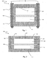
- a filtration device 100 comprises a first block 101 having a cavity which is a first chamber 110, a second block 102 also having a cavity which constitutes a second chamber 102, and a filter membrane 130 positioned between the first chamber 110 and the second chamber 120 and adjacent to each of the first and second chambers 110 , 120.
- these two chambers can receive a fluid to be filtered or a service fluid.
- the membrane 130 allows a material transport from one fluid to another by concentration difference or by pressure difference between the first and second chamber, or by any other known filtration cause of the man of the art.
- the first and second blocks 101, 102 may consist of glass, silica or, for example, polymers such as polymethyl methacrylate (PMMA) or polydimethylsiloxane (PDMS), or a mixture of these. this. PDMS has the advantage of being porous to oxygen.
- the two blocks can be made of the same material, or in different materials.
- the second chamber 120 is intended to receive a circulating fluid.
- the device 100 comprises a first opening 122 and a second opening 123 to allow the passage of a fluid. It further has an upper wall 121.
- membrane means a wall separating two media.
- a membrane has a porosity dependent on the size of its pores.
- the membrane separates the first chamber 110 and the second chamber 120 and defines a single closed space in complementarity with each of these chambers 110, 120.
- the membrane in the absence of pressure difference between the two chambers 110, 120, the membrane has no point of contact with the lower wall 111 of the first chamber 110, nor with the upper wall 121 of the second chamber 120.
- the first opening 122 (respectively the second opening 123) may be a fluid inlet in the second chamber 120 (respectively a fluid outlet of the second chamber 120) or a fluid outlet.
- the second chamber 120 (respectively a fluid inlet in the second chamber 120) depending on the direction of the current provided in the chamber 120.
- the first chamber 110 has a bottom wall 111 preferably having a substantially rectangular shape, which defines a length and a width.
- the length and the width of the bottom wall can respectively measure 13.25 mm and 11.23 mm
- the horizontal is defined as parallel to the bottom wall 111 and the vertical as orthogonal to the wall 111 and directed from the wall 111 to the membrane 130.
- the bottom wall 111 is horizontal and located in below the membrane 130, itself located below the upper wall 121.
- d1 direction of length of the lower wall 111 we note
- the first chamber 110 is for receiving a cell culture.
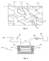
- the bottom wall 111 has a set of microstructures represented in three-dimensions on the figure 3 . These microstructures have been developed by the Applicant and have already been the subject, in their form, of a thesis report: "Development and characterization of a cell chip for the screening of toxic agents”.
- all surface of the bottom wall 111 is understood to mean the area that the bottom wall 111 would have if the microstructures were projected on the wall 111 in the vertical direction. This is the surface of the rectangle formed by the wall 111.
- Micromurs 111.3 have arrow-shaped portions and straight portions, and extend the entire length of the bottom wall 111.
- a micromur 111.3 defines microchamber 111.0 at its arrow-shaped portions in complementarity with another micromur 111.3, and microchannels 111.2 at its straight portions in complementarity with microplots 111.4, as shown in FIG. figure 2 .
- Each microplot 111.4 defines two microchannels located on either side of the microplot, each in complementarity with a micromur.
- the lower wall 111 of the first chamber 110 thus comprises periodic lines in its direction d1 in length, over its entire width.
- Each line comprises an alternation of microchannels 111.0 and microchannels 111.2, two lines being separated by a 111.3 micromur.
- each line may comprise 9 micro-chambers 111.0 and 8 pads 111.4 - each corresponding to two microchannels 111.2 - alternately, the lower wall 111 comprising a total of 15 lines.
- Such a device has on the bottom wall 111 a geometry favorable to the development of cells, particularly compared to flat culture devices such as Petri dishes.
- the microstructures allow a three-dimensional organization of the cells, provided they are fed with nutrient fluid containing elements necessary for the development of the cells, in particular oxygen or glucose.
- the device according to the first aspect of the invention allows a supply of cells without a nutrient fluid flow is required in the first chamber. Indeed, by disposing a stagnant fluid in the first chamber where the cells are caused to develop, and by circulating a nutrient fluid in the second chamber, the elements necessary for the development of cells (in particular glucose) pass into the fluid stagnant, provided that the membrane 130 is appropriately selected. In particular, it is possible to choose a membrane whose porosity is adapted to let glucose pass.
- the device 100 finds a first application in cell culture. Indeed, a circulating nutrient fluid can tear cells and disintegrate structures which is an obstacle to the development of cells and limits their activity.
- the device 100 described above makes it possible to overcome this difficulty by proposing a solution to the feed without circulation of fluid in direct contact with the cells.
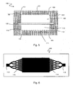
- the circulating fluid pressure in the second chamber can cause a deformation of the membrane 130 which then approaches the lower wall 111.
- the membrane 130 then constitutes a mechanical threat to the developing cells; it may disintegrate the cell structures and tear them off the wall 111.
- microstructures protect cells from this harmful effect. Indeed, even if the membrane 130 comes into contact with the lower wall 111, it would be in contact with micromurs 111.3 and 111.4 microplots, the cells can always develop in microchannels 111.0 and 111.2 microchannels. Thus, the microchannels and microchannels constitute a structure not only favorable to the development of the cells, but also protected in the case where the membrane 130 deforms to the lower wall 111.
- the device 100 thus described can be used in a filtration system according to the second aspect of the invention as shown in FIG. figure 4 .
- the system comprises, in addition to a device 100, a fluid circuit 300 comprising a circulation pipe 310 provided with a circulation means 320.
- "Piping” means a set of one or more pipes. These pipes may be flexible or rigid, and consist of any suitable material known to those skilled in the art.
- the fluid circuit 300 is connected to the first and second openings 122, 123 in the second chamber 120 through respective passages 151 and 152 in the second block 102.
- the circulation means 320 is preferably connected to a reserve 340 in a nutrient medium, and may comprise a liquid pump, a peristaltic pump, a set of valves, for example solenoid valves, or any other suitable means known to the person skilled in the art. art.
- the circuit 300 preferably comprises a discharge 350 for the nutrient fluid after passing through the second chamber 120.
- Such a system according to the second aspect of the invention is not limited to this representation in which the circuit 300 is open, and extends in particular to any system in which the circuit 300 is closed and optionally comprises a regeneration means nutrient fluid.
- the device 100 according to the first aspect of the invention is not limited to the description that has been made so far.
- the device 100 further comprises a fluid inlet 112 and a fluid outlet 113 as shown in FIG. figure 5 .
- the fluid inlet 112 is connected to at least a portion of the microchannels 111.2 via an input network 114.
- the input network 114 comprises successive branches for supplying each of the lines of the lower wall 111 of the first chamber from the fluid inlet 112.
- the fluid is intended to circulate at the microchannels 111.2 and microchannels 111.0, and above the microstructures in the first chamber 110, for example to supply the cells in development.
- the fluid outlet 113 is connected to at least a portion of the microchannels via an output network 115.
- the output network 115 includes successive confluence points for connecting each of the lines of the lower wall 111 of the chamber 110 to the fluid outlet 113.
- the microchannels 111.2 form a network connecting the fluid inlet 112 to each microchamber 111.0 - via the input network 114 - and each microchamber to the fluid outlet 113 - through the output network 115 .
- the microchannels 111.0 preferably comprise an inlet zone 111.5 and an outlet zone 111, 6 to allow the circulation of the fluid substantially in the direction of the length direction of the wall 111.
- a fluid containing molecules to be tested on the cells For example, it is possible to circulate in the chamber 110 a fluid containing molecules to be tested on the cells.
- This application is particularly interesting in the detection of substances that are toxic to humans: human cell tissue, nourished through the membrane by a nutrient fluid circulating in chamber 120 and exposed directly to test molecules in chamber 110, is cultured.
- Another possible application is the mechanical stimulation of cells.
- Certain cells such as endothelial cells, are naturally subject to flow conditions, such as blood. These cells are naturally activated by mechanical friction, which can be reproduced by circulation of the fluid in the first chamber 110.
- the micro-chambers 111.0 have a length dimension and a width dimension with respect to the direction d1 each of between 500 ⁇ m and 550 ⁇ m, preferably 520 ⁇ m.
- the dimensions of the microchannels 111.0 of the filtration device 100 are advantageously 520 ⁇ m ⁇ 520 ⁇ m ⁇ 100 ⁇ m.
- the microchannels 111.2 have, with respect to the direction d1, a length dimension of between 700 ⁇ m and 750 ⁇ m, preferably of 720 ⁇ m, and a width dimension of between 200 ⁇ m and 250 ⁇ m, preferably of 220 ⁇ m.
- the dimensions of the microchannels 111.2 of the device 100 are advantageously 720 ⁇ m ⁇ 220 ⁇ m ⁇ 100 ⁇ m.
- the microchannels 111.2 thus sized facilitate the development of liver cells; they allow in particular the migration of liver organ piece through the microchannel network.
- micromurs 111.3, 111.4 microplots and 111.2 microchannels We also represented on the figure 7 several other dimensions characteristic of micromurs 111.3, 111.4 microplots and 111.2 microchannels for a possible embodiment of the filter device 100 of the first aspect of the invention.
- the micromurs 111.3 comprise angular zones 111.7 on either side of the entry zone 111.5 and of the exit zone 111.6 of at least one chamber 111.0, as shown in FIGS. figures 3 and 7 .
- These angular zones 111.7 have a dimension of width with respect to the direction d1 advantageously between 100 ⁇ m and 120 ⁇ m, preferably 110 ⁇ m. In particular, they have a transverse edge to the direction d1 fluid flow.
- the angular zones 111.7 define, with respect to the direction d1, partially protected zones on either side of the inlet zone 111.5 of said chamber 110, that is to say zones where the circulation of the fluid is brutally slowed down.
- the partially protected areas have, according to this advantageous variant of the first aspect of the invention, a transverse edge in the direction d1 with a width of at least 100 .mu.m.
- hepatic cells are capable of aggregating into a spheroid of large diameter, of the order of 100 .mu.m, a form favorable to good cellular activity.
- culture surface denotes all of these development zones.
- the ratio between the culture surface and the overall surface of the bottom wall 111 is between 90% and 110%. It is preferably equal to 100% to an accuracy of 1%.
- the cultivation surface is 151mm 2 .
- the cultivation area ratio on the overall surface of the bottom wall is, in this example, 101%.
- the microstructures on the bottom wall 111 hardly change the area available for cultivation relative to the overall surface of the bottom wall 111, while allowing three-dimensional development.
- cells may also develop on the upper surfaces of 111.3 micromurs and 111.4 microplots, although such areas are not particularly favorable for three-dimensional development.
- total culture surface is then referred to as the previously defined culture surface to which the upper surfaces of the micromurs 111.3 and the microplots 111.4 are added.
- these upper surfaces are 52.5mm 2 and the total culture area is 203.5mm 2 and the ratio of the total culture area to the overall area of the bottom wall is 137%.
- the culture chamber 110 has a volume and the ratio R2 between the total culture surface and the volume of the culture chamber 110 is between 4 mm -1 and 6 mm -1.
- the cells may be confined and not have enough nutrients distributed by the fluid, which is detrimental to their development.
- the volume of the first chamber 110 is understood to mean the volume available for the passage of the fluid; therefore, the volume occupied by the 111.3 micromurs and the 111.4 microplots is excluded.
- the upper surface 121 of the second chamber 120 also has microstructures.
- These microstructures may have all the advantageous variants of the microstructures detailed hitherto concerning the lower wall 111 of the first chamber 110.
- the microstructures may be of identical dimensions on the lower walls 111 and 121, or of different dimensions. This variant is particularly interesting for an application for cell culture in both chambers
- the membrane 130 is preferably made of flexible material and can thus be slightly deformable as a function of the pressure prevailing in each of the chambers 110, 120. As has been seen previously, the microstructures prevent the membrane 130 from sticking to the walls and protecting the culture cells of a possible contact with the membrane 130.
- the membrane 130 may be hydrophilic or hydrophobic, and will be selected according to the intended application (dialysis, cell culture, etc.).
- a membrane is said to be hydrophilic when there is interaction of the terminal groups with water by hydrogen bonding.
- Hydrophilic membranes like cellulose membranes, have a good diffusion and as they have a low adsorption of proteins, they have a good convection; on the other hand, the biocompatibility is poor. They are used in dialysis to let water and very small solutes.
- Hydrophobic membranes like synthetic ones, have a lower diffusion, but a higher ultrafiltration coefficient because of their porous structure which counteracts the negative effect of protein adsorption; the latter is at the origin of the best biocompatibility. They are often used in haemodiafiltration. The biocompatibility of membranes makes many applications of these membranes with cell culture.
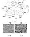
- the membranes can be microstructured with micro-pores microstructures (see Figures 8a and 8b ) but also with micro pores which could also take the form of microchannels or micro pillars or micro geometries, for example geometries as illustrated on the diagram. figure 7 .
- the membrane 130 may be hydrophilic, which limits the adhesion of bacteria and proteins and decreases the resistance of the fluid passage in the pores of the membrane 130.
- the membrane 130 may be hydrophobic, which limits the adhesion of bacteria, facilitates the adhesion of proteins and increases the resistance of the passage of fluid in the pores.
- the membrane 130 is preferably a barrier membrane, that is to say that it only allows small molecules or gases to diffuse and prevents the passage of fluids from a chamber 110, 120, to the other room 120, 110.
- the Figures 8a and 8b show images taken by electron microscope of two examples of membranes 130a, 130b of polyethersulfone filtration with a respective porosity of 40000 Da and 500000 Da.
- the membrane 130 is chosen to allow cell culture on the membrane 130.
- membrane like MDCK or Caco-2 cells.
- the membrane 130 has a surface of the order of cm 2 .
- the filtration device 100 comprises a holding means 160 for holding together the first block 101, the membrane 130 and the second block 102 in this order.
- the means 160 has a locked configuration in which the first block 101 and the membrane 130 are secured, on the other hand the membrane 130 and the second block, and an unlocked configuration, in which the block 101 and the membrane 130 are separable from one another and / or wherein the membrane 130 and the second block 102 are separable from each other.
- the holding means 160 can be switched from the locked configuration to the unlocked configuration and vice versa, for example by action of a user.
- the means 160 may comprise screws passing through their entire height the first block 101, the membrane 130 and the second block 102, as shown in FIG. figure 1 .
- the means 160 may also include cleats, a vise, or any other suitable means known to those skilled in the art.
- Such a holding means 160 has several advantages. It makes it possible to separate the device 100 in its constituents and to be able to reconstruct it afterwards. Thus, chambers 110 and 120, as well as membrane 130, can be accessed without rendering the device 100 unusable.
- This is particularly useful for cleaning the chambers of the molecules to be filtered which have adsorbed on the surfaces and sterilize them, for example by autoclave or by any other suitable cleaning method known to those skilled in the art.
- the membrane 130 can be recovered for analysis, such as transmembrane electrical resistance measurements, the recovery of the membrane to make fluorescent markings on the membranes. cells, impedance analyzes, or any other useful analysis known to those skilled in the art.
- the means 160 also offers the possibility of direct access to the cell culture by avoiding the evacuation of this culture from the device 100 by a fluid which would destroy the culture structure.
- the membrane can be replaced by a new membrane for repetitive experiments without the need for cleaning. It is thus possible to repeat an experiment by changing the membrane 130 while keeping intact the cellular contents of the chambers 110, 120.
- membrane 130 can be transplanted from one device 100 to another and be tested with chambers 110, 120 with different microstructure geometry. This may be useful for characterizing the effect of microstructures on filtration or cell culture on membrane 130.
- the device 100 integrated in the filtration system comprises a fluid inlet 112 and a fluid outlet 113 in the first chamber 110.
- the system comprises a fluid circuit 200 connected to the first chamber 110, similar to the circuit 300 connected to the second chamber 120 that has already been described above.
- the fluid circuit 200 comprises a circulation pipe 210 provided with a circulation means 220 and is connected to the inlet 112 and outlet 113 in the first chamber 110.
- the fluid circuit 200 is connected to the fluid inlet 112 and outlet 113 in the first chamber 110, through respective passages 141 and 142 in the first block 101.
- the circulation means 220 is preferably connected to a reserve 240 in fluid, and may comprise a liquid pump, a peristaltic pump, a set of valves, for example solenoid valves, or any other suitable means known to those skilled in the art. .
- circuit 200 preferably comprises an evacuation 250 for the fluid after passing through the first chamber 110.
- Such a system according to the second aspect of the invention is not limited to this representation in which the circuit 200 is open, and extends in particular to any system in which the circuit 200 is closed and optionally comprises a fluid regeneration means.
- the fluids circulating in the circuits 200 and / or 300 are advantageously temperature-controlled.
- reserves 240 and / or 340 may be arranged in thermostatic baths (not shown).
- any other means of controlling the temperature of the circuits 200 and / or 300 known to those skilled in the art can be envisaged.
- the fluids contained in the lower chamber 110 and upper 120 circulate cocurrently.
- the first opening 122 is a fluid outlet of the second chamber 120 and the second opening 123 is a fluid inlet in the second chamber 120.
- the first opening 122 is a fluid inlet in the second chamber 120 and the second opening 123 is a fluid outlet of the second chamber 120.
- Blood to be treated may circulate in the second chamber 120 and be freed of certain components ordinarily removed by a functional kidney by filtration through the membrane 130.
- a dialysis fluid contained in the first chamber 110 then makes it possible to evacuate the filtered elements and to provide a glucose supply for the patient.
- Such systems can also be used to characterize a filtration membrane 130.
- a diffusion coefficient of a molecule for a given membrane 130 can be evaluated from a physical model and from measurements of the concentrations of the molecule in the first chamber 110 and / or the second chamber 120 as a function of time.
- the co-current system can be used to calibrate the model and estimate the diffusion coefficient, and the countercurrent system can be used to verify the diffusion coefficient, or vice versa.
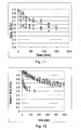
- the experimental results are represented, for an experiment with the membrane with high porosity (of type 8F), by the icons,, ⁇ , and for a experiment with membrane low porosity (of type 1 FPH), by the icons: *, o.
- the circulation circuit 200 advantageously comprises a fluid pressure control means 230 in the first chamber 110
- the circulation circuit 300 advantageously comprises a fluid pressure control means 330 in the second chamber 120
- the two circuits 200, 300 each comprise a pressure control means 230, 330 in their associated chamber 110, 120.
- control means 230 comprises pressure sensors 231, 232 (respectively 331, 332) for detecting a pressure of the fluid in the passages 141, 142 in the first block 101 (respectively 151, 152 in the second block 102) or at the fluid inlet and outlet 112, 113 (respectively at the first and second openings 122, 123).
- the means 230 further comprises actuators 233, 234 (respectively 333, 334) disposed on the pipe 210 (respectively 310) for modifying the pressure at the inlet and at the outlet of the fluid in the first chamber 110 (respectively in the second bedroom 120).
- actuators may be for example solenoid valves controlled by a processing unit (not shown) of data from the pressure sensors, or any other suitable means known to those skilled in the art.
- the pressure checks can be carried out by the processing unit of each control means 230, 330 by stabilizing the pressure around a fixed or variable setpoint value, for example by applying a proportional controller, an integral proportional controller, an open loop (in which case the pressure sensors are not used), or any other suitable control loop known to the person in charge. system control profession.
- control means 230, 330 of the circuits 200, 300 may be similar or different depending on the needs of the application envisaged for the filtration system according to the second aspect of the invention.
- the pressure difference can be maintained at a predetermined value so that the membrane does not adhere to the walls.
- the means 230, 330 make it possible to control the flow conditions in the chambers 110, 120 and the transmembrane flow during the filtration. This makes it possible to regulate filtration parameters for a given solute, such as the rejection rate - that is to say the percentage of dissolved material retained by the membrane - and the diffusion coefficient of the solute through the membrane 130 .
- the means 230, 330 make it possible to carry out repetitive experiments under the same conditions of flow and transmembrane flow.
- a particularly interesting application of this advantageous effect is to test different membranes under similar conditions of experiment, which makes it possible to characterize the properties of the membranes, for example the slope with water - that is to say the hydraulic permeability membranes with pure water - for example through the experiment shown in the figure 14 .
- the fluid flowing in the second chamber 120 is water.
- the first circuit 200 does not include a reserve 240 or a circulation means 220, in which case the short-circuit means 250 is unnecessary.
- the resist 240 and the means 220 are surrounded by a dashed rectangle on the figure 14 .
- the evacuation 350 of the second circuit 300 is blocking for water (for example a closed tap).
- the water circulating in the second chamber through the second opening 152 can only exit the device 100 through the passage 142 of the first block 101, which passage 142 is connected to the discharge 250 of the first circuit 200 by the pipe 210.
- the system according to this variant of the second aspect of the invention is associated with a device 400 for measuring the mass of water, comprising a container 410 connected to the outlet 250, a balance 420 and a treatment unit 430. interaction with the barnacle 420 and for determining the mass of water contained in the container 410 as a function of time. Furthermore, the processing unit receives information from the control means 230, 330 of pressure in the two circuits 200, 300.
- the device 400 is capable of evaluating the mass of filtering water by the membrane 130 as a function of time and of the transmembrane pressure, which makes it possible to determine the slope with water of the membrane 130.
- the experiment was conducted by the Applicant on the membranes 130a and 130b respectively represented on the Figures 8a and 8b .
- the determined water slopes are 8ml / (min.bar.cm 3 ) and 80ml / (min.bar.cm 3 ) respectively.
- Another application is to measure the pressure losses in the first chamber 110 (and in the second chamber 120 if it receives a culture of cells), which losses give an indication of the variations in the number of culture cells in the chamber .
- the invention has many advantages.
- the system according to the second aspect of the invention allows controlled filtration over larger systems.
- the fluid circuits do not experience turbulence and little edge effect, both in the piping and in the chambers of the device according to the first aspect of the invention.
- the pressure control means and the membrane make it possible to maintain uniform parameters (pressure, temperature, composition and concentration of the fluids) so that the observed results can easily be extrapolated to systems with similar parameters.
- the invention constitutes a major step towards in vitro reproduction of phenomena of the human or animal body, as well as towards the realization of artificial organs.
Landscapes
- Health & Medical Sciences (AREA)
- Chemical & Material Sciences (AREA)
- Organic Chemistry (AREA)
- Wood Science & Technology (AREA)
- Life Sciences & Earth Sciences (AREA)
- Engineering & Computer Science (AREA)
- Zoology (AREA)
- Bioinformatics & Cheminformatics (AREA)
- Sustainable Development (AREA)
- Biomedical Technology (AREA)
- Biotechnology (AREA)
- Biochemistry (AREA)
- General Engineering & Computer Science (AREA)
- General Health & Medical Sciences (AREA)
- Genetics & Genomics (AREA)
- Microbiology (AREA)
- Clinical Laboratory Science (AREA)
- Immunology (AREA)
- Dispersion Chemistry (AREA)
- Apparatus Associated With Microorganisms And Enzymes (AREA)
- External Artificial Organs (AREA)
- Separation Using Semi-Permeable Membranes (AREA)
Applications Claiming Priority (2)
| Application Number | Priority Date | Filing Date | Title |
|---|---|---|---|
| FR0956568A FR2950359B1 (fr) | 2009-09-23 | 2009-09-23 | Dispositif et systeme de filtration |
| PCT/EP2010/064082 WO2011036226A2 (fr) | 2009-09-23 | 2010-09-23 | Dispositif et systeme de filtration |
Publications (2)
| Publication Number | Publication Date |
|---|---|
| EP2480654A2 EP2480654A2 (fr) | 2012-08-01 |
| EP2480654B1 true EP2480654B1 (fr) | 2015-06-17 |
Family
ID=42211816
Family Applications (1)
| Application Number | Title | Priority Date | Filing Date |
|---|---|---|---|
| EP10757102.8A Active EP2480654B1 (fr) | 2009-09-23 | 2010-09-23 | Dispositif et systeme de filtration |
Country Status (7)
| Country | Link |
|---|---|
| US (2) | US20130005027A1 (enExample) |
| EP (1) | EP2480654B1 (enExample) |
| JP (1) | JP5956340B2 (enExample) |
| CA (1) | CA2774952C (enExample) |
| FR (1) | FR2950359B1 (enExample) |
| IL (1) | IL218794A (enExample) |
| WO (1) | WO2011036226A2 (enExample) |
Families Citing this family (6)
| Publication number | Priority date | Publication date | Assignee | Title |
|---|---|---|---|---|
| US20150072413A1 (en) * | 2012-03-29 | 2015-03-12 | Arizona Board Of Regents On Behalf University Of Arizona | Cell culture apparatus and culture methods using same |
| KR101807765B1 (ko) * | 2012-11-16 | 2017-12-11 | 주식회사 케이티 | 모바일 결제 시스템 및 방법 |
| EP3400976A1 (en) * | 2017-05-12 | 2018-11-14 | Universitat Rovira i Virgili | Device and method for the preparation of platelet rich plasma |
| EP3837273B1 (en) | 2018-08-14 | 2025-09-24 | Bristol-Myers Squibb Company | Improved protein recovery |
| US20230113710A1 (en) * | 2021-10-08 | 2023-04-13 | Shanghai Ruiyu Biotech Co., Ltd. | Culture devices |
| EP4633812A2 (en) * | 2022-12-13 | 2025-10-22 | Rapid Micro Biosystems, Inc. | Tube set with dual pressure regulating valve |
Family Cites Families (14)
| Publication number | Priority date | Publication date | Assignee | Title |
|---|---|---|---|---|
| US5763266A (en) * | 1989-06-15 | 1998-06-09 | The Regents Of The University Of Michigan | Methods, compositions and devices for maintaining and growing human stem and/or hematopoietics cells |
| JPH05292990A (ja) * | 1992-04-09 | 1993-11-09 | Tabai Espec Corp | 物質の生産方法および該方法に用いる細胞培養器 |
| US5801055A (en) * | 1997-09-10 | 1998-09-01 | Becton Dickinson And Company | Multi-well culture dish assembly |
| ATE227338T1 (de) * | 1998-03-18 | 2002-11-15 | Massachusetts Inst Technology | Vaskularisierte perfundierte anordnungen für mikrogewebe und mikroorgane |
| US7776021B2 (en) * | 2000-04-28 | 2010-08-17 | The Charles Stark Draper Laboratory | Micromachined bilayer unit for filtration of small molecules |
| SE0004296D0 (sv) * | 2000-11-23 | 2000-11-23 | Gyros Ab | Device and method for the controlled heating in micro channel systems |
| US20030215941A1 (en) * | 2002-03-12 | 2003-11-20 | Stewart Campbell | Assay device that analyzes the absorption, metabolism, permeability and/or toxicity of a candidate compound |
| US20040018611A1 (en) * | 2002-07-23 | 2004-01-29 | Ward Michael Dennis | Microfluidic devices for high gradient magnetic separation |
| AU2003268202A1 (en) * | 2002-08-27 | 2004-03-19 | Vanderbilt University | Bioreactors with an array of chambers and a common feed line |
| US6878271B2 (en) * | 2002-09-09 | 2005-04-12 | Cytonome, Inc. | Implementation of microfluidic components in a microfluidic system |
| WO2004024300A1 (en) * | 2002-09-11 | 2004-03-25 | The Regents Of The University Of Michigan | Ultrafiltration membrane, device, bioartificial organ and methods |
| US7476326B2 (en) * | 2003-09-26 | 2009-01-13 | Ahn Chong H | On-chip sample preparation for whole blood analysis |
| US8003380B2 (en) * | 2006-01-04 | 2011-08-23 | Agency For Science, Technology And Research | High throughput cell-based assays fabricated with integrated silicon and cell culture technologies |
| EP2169049B1 (en) * | 2007-06-18 | 2018-01-17 | Kuraray Co., Ltd. | Cell culture container and cell culture method |
-
2009
- 2009-09-23 FR FR0956568A patent/FR2950359B1/fr not_active Expired - Fee Related
-
2010
- 2010-09-23 EP EP10757102.8A patent/EP2480654B1/fr active Active
- 2010-09-23 CA CA2774952A patent/CA2774952C/fr active Active
- 2010-09-23 WO PCT/EP2010/064082 patent/WO2011036226A2/fr not_active Ceased
- 2010-09-23 US US13/497,247 patent/US20130005027A1/en not_active Abandoned
- 2010-09-23 JP JP2012530264A patent/JP5956340B2/ja active Active
-
2012
- 2012-03-22 IL IL218794A patent/IL218794A/en active IP Right Grant
-
2016
- 2016-12-16 US US15/382,437 patent/US20170096629A1/en not_active Abandoned
Also Published As
| Publication number | Publication date |
|---|---|
| IL218794A (en) | 2015-05-31 |
| US20170096629A1 (en) | 2017-04-06 |
| FR2950359A1 (fr) | 2011-03-25 |
| CA2774952C (fr) | 2018-05-15 |
| EP2480654A2 (fr) | 2012-08-01 |
| JP2013505029A (ja) | 2013-02-14 |
| CA2774952A1 (fr) | 2011-03-31 |
| JP5956340B2 (ja) | 2016-07-27 |
| IL218794A0 (en) | 2012-06-28 |
| WO2011036226A3 (fr) | 2011-12-29 |
| WO2011036226A2 (fr) | 2011-03-31 |
| FR2950359B1 (fr) | 2011-12-02 |
| US20130005027A1 (en) | 2013-01-03 |
Similar Documents
| Publication | Publication Date | Title |
|---|---|---|
| EP2480654B1 (fr) | Dispositif et systeme de filtration | |
| EP0822976B1 (fr) | Bioreacteur | |
| US10730016B2 (en) | Ultrafiltration membrane, device, bioartificial organ, and related methods | |
| Deshpande et al. | Mechanical division of cell-sized liposomes | |
| EP2119503B1 (fr) | Système microfluidique et procédé pour le tri d'amas de cellules et pour leur encapsulation en continu suite à leur tri | |
| US20060213836A1 (en) | Ultrafiltration membrane,device, bioartificial organ, and methods | |
| FR2690926A1 (fr) | Dispositif du type réacteur à volume variable et procédé de culture cellulaire. | |
| WO2002006441A1 (fr) | Chambre de culture cellulaire et bioreacteur pour la culture extracorporelle de cellules animales | |
| JP6027010B2 (ja) | 固定のためのフィルタアセンブリ | |
| Mager et al. | Lipid bilayer deposition and patterning via air bubble collapse | |
| EP2705132A1 (fr) | Procédé pour la récolte de microalgues et dispositif pour la mise en oeuvre de ce procédé | |
| WO2001014514A1 (fr) | Dispositif a usage biologique, notamment pour la culture cellulaire | |
| WO2010149567A2 (fr) | Bioreacteur pour cultiver des cellules | |
| FR2957086A1 (fr) | Boite multi-reacteurs pour culture cellulaire dynamique | |
| EP3805362A1 (fr) | Méthode de fabrication d'une structure vasculaire | |
| EP4558604A1 (fr) | Assemblage et culture d'objets cellulaires sur une structure de contact sous l'action de forces de radiation acoustique axiale et transversale | |
| WO2023222631A1 (fr) | Puce microfluidique pour croissance cellulaire | |
| WO2012066055A1 (fr) | Dispositif d'analyse des effets d'au moins un parametre relatif a une substance volatile |
Legal Events
| Date | Code | Title | Description |
|---|---|---|---|
| PUAI | Public reference made under article 153(3) epc to a published international application that has entered the european phase |
Free format text: ORIGINAL CODE: 0009012 |
|
| 17P | Request for examination filed |
Effective date: 20120329 |
|
| AK | Designated contracting states |
Kind code of ref document: A2 Designated state(s): AL AT BE BG CH CY CZ DE DK EE ES FI FR GB GR HR HU IE IS IT LI LT LU LV MC MK MT NL NO PL PT RO SE SI SK SM TR |
|
| DAX | Request for extension of the european patent (deleted) | ||
| GRAP | Despatch of communication of intention to grant a patent |
Free format text: ORIGINAL CODE: EPIDOSNIGR1 |
|
| INTG | Intention to grant announced |
Effective date: 20140924 |
|
| GRAP | Despatch of communication of intention to grant a patent |
Free format text: ORIGINAL CODE: EPIDOSNIGR1 |
|
| INTG | Intention to grant announced |
Effective date: 20150312 |
|
| GRAS | Grant fee paid |
Free format text: ORIGINAL CODE: EPIDOSNIGR3 |
|
| GRAA | (expected) grant |
Free format text: ORIGINAL CODE: 0009210 |
|
| AK | Designated contracting states |
Kind code of ref document: B1 Designated state(s): AL AT BE BG CH CY CZ DE DK EE ES FI FR GB GR HR HU IE IS IT LI LT LU LV MC MK MT NL NO PL PT RO SE SI SK SM TR |
|
| REG | Reference to a national code |
Ref country code: GB Ref legal event code: FG4D Free format text: NOT ENGLISH |
|
| REG | Reference to a national code |
Ref country code: CH Ref legal event code: EP |
|
| REG | Reference to a national code |
Ref country code: AT Ref legal event code: REF Ref document number: 731956 Country of ref document: AT Kind code of ref document: T Effective date: 20150715 |
|
| REG | Reference to a national code |
Ref country code: IE Ref legal event code: FG4D Free format text: LANGUAGE OF EP DOCUMENT: FRENCH |
|
| REG | Reference to a national code |
Ref country code: DE Ref legal event code: R096 Ref document number: 602010025312 Country of ref document: DE |
|
| REG | Reference to a national code |
Ref country code: CH Ref legal event code: NV Representative=s name: MICHELI AND CIE SA, CH |
|
| PG25 | Lapsed in a contracting state [announced via postgrant information from national office to epo] |
Ref country code: NO Free format text: LAPSE BECAUSE OF FAILURE TO SUBMIT A TRANSLATION OF THE DESCRIPTION OR TO PAY THE FEE WITHIN THE PRESCRIBED TIME-LIMIT Effective date: 20150917 Ref country code: FI Free format text: LAPSE BECAUSE OF FAILURE TO SUBMIT A TRANSLATION OF THE DESCRIPTION OR TO PAY THE FEE WITHIN THE PRESCRIBED TIME-LIMIT Effective date: 20150617 Ref country code: LT Free format text: LAPSE BECAUSE OF FAILURE TO SUBMIT A TRANSLATION OF THE DESCRIPTION OR TO PAY THE FEE WITHIN THE PRESCRIBED TIME-LIMIT Effective date: 20150617 Ref country code: HR Free format text: LAPSE BECAUSE OF FAILURE TO SUBMIT A TRANSLATION OF THE DESCRIPTION OR TO PAY THE FEE WITHIN THE PRESCRIBED TIME-LIMIT Effective date: 20150617 |
|
| REG | Reference to a national code |
Ref country code: AT Ref legal event code: MK05 Ref document number: 731956 Country of ref document: AT Kind code of ref document: T Effective date: 20150617 |
|
| REG | Reference to a national code |
Ref country code: LT Ref legal event code: MG4D Ref country code: NL Ref legal event code: MP Effective date: 20150617 |
|
| PG25 | Lapsed in a contracting state [announced via postgrant information from national office to epo] |
Ref country code: GR Free format text: LAPSE BECAUSE OF FAILURE TO SUBMIT A TRANSLATION OF THE DESCRIPTION OR TO PAY THE FEE WITHIN THE PRESCRIBED TIME-LIMIT Effective date: 20150918 Ref country code: LV Free format text: LAPSE BECAUSE OF FAILURE TO SUBMIT A TRANSLATION OF THE DESCRIPTION OR TO PAY THE FEE WITHIN THE PRESCRIBED TIME-LIMIT Effective date: 20150617 Ref country code: BG Free format text: LAPSE BECAUSE OF FAILURE TO SUBMIT A TRANSLATION OF THE DESCRIPTION OR TO PAY THE FEE WITHIN THE PRESCRIBED TIME-LIMIT Effective date: 20150917 |
|
| PG25 | Lapsed in a contracting state [announced via postgrant information from national office to epo] |
Ref country code: EE Free format text: LAPSE BECAUSE OF FAILURE TO SUBMIT A TRANSLATION OF THE DESCRIPTION OR TO PAY THE FEE WITHIN THE PRESCRIBED TIME-LIMIT Effective date: 20150617 |
|
| PG25 | Lapsed in a contracting state [announced via postgrant information from national office to epo] |
Ref country code: RO Free format text: LAPSE BECAUSE OF NON-PAYMENT OF DUE FEES Effective date: 20150617 Ref country code: AT Free format text: LAPSE BECAUSE OF FAILURE TO SUBMIT A TRANSLATION OF THE DESCRIPTION OR TO PAY THE FEE WITHIN THE PRESCRIBED TIME-LIMIT Effective date: 20150617 Ref country code: CZ Free format text: LAPSE BECAUSE OF FAILURE TO SUBMIT A TRANSLATION OF THE DESCRIPTION OR TO PAY THE FEE WITHIN THE PRESCRIBED TIME-LIMIT Effective date: 20150617 Ref country code: PL Free format text: LAPSE BECAUSE OF FAILURE TO SUBMIT A TRANSLATION OF THE DESCRIPTION OR TO PAY THE FEE WITHIN THE PRESCRIBED TIME-LIMIT Effective date: 20150617 Ref country code: PT Free format text: LAPSE BECAUSE OF FAILURE TO SUBMIT A TRANSLATION OF THE DESCRIPTION OR TO PAY THE FEE WITHIN THE PRESCRIBED TIME-LIMIT Effective date: 20151019 Ref country code: ES Free format text: LAPSE BECAUSE OF FAILURE TO SUBMIT A TRANSLATION OF THE DESCRIPTION OR TO PAY THE FEE WITHIN THE PRESCRIBED TIME-LIMIT Effective date: 20150617 Ref country code: SK Free format text: LAPSE BECAUSE OF FAILURE TO SUBMIT A TRANSLATION OF THE DESCRIPTION OR TO PAY THE FEE WITHIN THE PRESCRIBED TIME-LIMIT Effective date: 20150617 Ref country code: IS Free format text: LAPSE BECAUSE OF FAILURE TO SUBMIT A TRANSLATION OF THE DESCRIPTION OR TO PAY THE FEE WITHIN THE PRESCRIBED TIME-LIMIT Effective date: 20151017 |
|
| REG | Reference to a national code |
Ref country code: DE Ref legal event code: R097 Ref document number: 602010025312 Country of ref document: DE |
|
| PLBE | No opposition filed within time limit |
Free format text: ORIGINAL CODE: 0009261 |
|
| STAA | Information on the status of an ep patent application or granted ep patent |
Free format text: STATUS: NO OPPOSITION FILED WITHIN TIME LIMIT |
|
| PG25 | Lapsed in a contracting state [announced via postgrant information from national office to epo] |
Ref country code: IT Free format text: LAPSE BECAUSE OF FAILURE TO SUBMIT A TRANSLATION OF THE DESCRIPTION OR TO PAY THE FEE WITHIN THE PRESCRIBED TIME-LIMIT Effective date: 20150617 Ref country code: LU Free format text: LAPSE BECAUSE OF FAILURE TO SUBMIT A TRANSLATION OF THE DESCRIPTION OR TO PAY THE FEE WITHIN THE PRESCRIBED TIME-LIMIT Effective date: 20150923 Ref country code: MC Free format text: LAPSE BECAUSE OF FAILURE TO SUBMIT A TRANSLATION OF THE DESCRIPTION OR TO PAY THE FEE WITHIN THE PRESCRIBED TIME-LIMIT Effective date: 20150617 Ref country code: DK Free format text: LAPSE BECAUSE OF FAILURE TO SUBMIT A TRANSLATION OF THE DESCRIPTION OR TO PAY THE FEE WITHIN THE PRESCRIBED TIME-LIMIT Effective date: 20150617 |
|
| 26N | No opposition filed |
Effective date: 20160318 |
|
| PG25 | Lapsed in a contracting state [announced via postgrant information from national office to epo] |
Ref country code: SI Free format text: LAPSE BECAUSE OF FAILURE TO SUBMIT A TRANSLATION OF THE DESCRIPTION OR TO PAY THE FEE WITHIN THE PRESCRIBED TIME-LIMIT Effective date: 20150617 |
|
| REG | Reference to a national code |
Ref country code: FR Ref legal event code: PLFP Year of fee payment: 7 |
|
| PG25 | Lapsed in a contracting state [announced via postgrant information from national office to epo] |
Ref country code: MT Free format text: LAPSE BECAUSE OF FAILURE TO SUBMIT A TRANSLATION OF THE DESCRIPTION OR TO PAY THE FEE WITHIN THE PRESCRIBED TIME-LIMIT Effective date: 20150617 |
|
| PG25 | Lapsed in a contracting state [announced via postgrant information from national office to epo] |
Ref country code: HU Free format text: LAPSE BECAUSE OF FAILURE TO SUBMIT A TRANSLATION OF THE DESCRIPTION OR TO PAY THE FEE WITHIN THE PRESCRIBED TIME-LIMIT; INVALID AB INITIO Effective date: 20100923 Ref country code: SM Free format text: LAPSE BECAUSE OF FAILURE TO SUBMIT A TRANSLATION OF THE DESCRIPTION OR TO PAY THE FEE WITHIN THE PRESCRIBED TIME-LIMIT Effective date: 20150617 |
|
| PG25 | Lapsed in a contracting state [announced via postgrant information from national office to epo] |
Ref country code: CY Free format text: LAPSE BECAUSE OF FAILURE TO SUBMIT A TRANSLATION OF THE DESCRIPTION OR TO PAY THE FEE WITHIN THE PRESCRIBED TIME-LIMIT Effective date: 20150617 Ref country code: SE Free format text: LAPSE BECAUSE OF FAILURE TO SUBMIT A TRANSLATION OF THE DESCRIPTION OR TO PAY THE FEE WITHIN THE PRESCRIBED TIME-LIMIT Effective date: 20150617 Ref country code: NL Free format text: LAPSE BECAUSE OF FAILURE TO SUBMIT A TRANSLATION OF THE DESCRIPTION OR TO PAY THE FEE WITHIN THE PRESCRIBED TIME-LIMIT Effective date: 20150617 |
|
| PG25 | Lapsed in a contracting state [announced via postgrant information from national office to epo] |
Ref country code: TR Free format text: LAPSE BECAUSE OF FAILURE TO SUBMIT A TRANSLATION OF THE DESCRIPTION OR TO PAY THE FEE WITHIN THE PRESCRIBED TIME-LIMIT Effective date: 20150617 |
|
| REG | Reference to a national code |
Ref country code: FR Ref legal event code: PLFP Year of fee payment: 8 |
|
| PG25 | Lapsed in a contracting state [announced via postgrant information from national office to epo] |
Ref country code: MK Free format text: LAPSE BECAUSE OF FAILURE TO SUBMIT A TRANSLATION OF THE DESCRIPTION OR TO PAY THE FEE WITHIN THE PRESCRIBED TIME-LIMIT Effective date: 20150617 |
|
| REG | Reference to a national code |
Ref country code: FR Ref legal event code: PLFP Year of fee payment: 9 |
|
| PG25 | Lapsed in a contracting state [announced via postgrant information from national office to epo] |
Ref country code: AL Free format text: LAPSE BECAUSE OF FAILURE TO SUBMIT A TRANSLATION OF THE DESCRIPTION OR TO PAY THE FEE WITHIN THE PRESCRIBED TIME-LIMIT Effective date: 20150617 |
|
| PGFP | Annual fee paid to national office [announced via postgrant information from national office to epo] |
Ref country code: DE Payment date: 20241115 Year of fee payment: 15 |
|
| PGFP | Annual fee paid to national office [announced via postgrant information from national office to epo] |
Ref country code: CH Payment date: 20241224 Year of fee payment: 15 |
|
| REG | Reference to a national code |
Ref country code: CH Ref legal event code: U11 Free format text: ST27 STATUS EVENT CODE: U-0-0-U10-U11 (AS PROVIDED BY THE NATIONAL OFFICE) Effective date: 20251002 |
|
| PGFP | Annual fee paid to national office [announced via postgrant information from national office to epo] |
Ref country code: BE Payment date: 20250929 Year of fee payment: 16 Ref country code: GB Payment date: 20250929 Year of fee payment: 16 |
|
| PGFP | Annual fee paid to national office [announced via postgrant information from national office to epo] |
Ref country code: FR Payment date: 20250929 Year of fee payment: 16 |
|
| PGFP | Annual fee paid to national office [announced via postgrant information from national office to epo] |
Ref country code: IE Payment date: 20250929 Year of fee payment: 16 |