EP2480654B1 - Filtration device and system - Google Patents
Filtration device and system Download PDFInfo
- Publication number
- EP2480654B1 EP2480654B1 EP10757102.8A EP10757102A EP2480654B1 EP 2480654 B1 EP2480654 B1 EP 2480654B1 EP 10757102 A EP10757102 A EP 10757102A EP 2480654 B1 EP2480654 B1 EP 2480654B1
- Authority
- EP
- European Patent Office
- Prior art keywords
- chamber
- fluid
- membrane
- micro
- circulation
- Prior art date
- Legal status (The legal status is an assumption and is not a legal conclusion. Google has not performed a legal analysis and makes no representation as to the accuracy of the status listed.)
- Active
Links
- 238000001914 filtration Methods 0.000 title claims description 76
- 239000012528 membrane Substances 0.000 claims description 138
- 239000012530 fluid Substances 0.000 claims description 127
- 230000004087 circulation Effects 0.000 claims description 42
- 239000000463 material Substances 0.000 claims description 11
- 238000005259 measurement Methods 0.000 claims description 8
- 210000004379 membrane Anatomy 0.000 description 125
- 210000004027 cell Anatomy 0.000 description 41
- 238000011161 development Methods 0.000 description 16
- 230000018109 developmental process Effects 0.000 description 16
- 238000004113 cell culture Methods 0.000 description 15
- 238000009792 diffusion process Methods 0.000 description 14
- 238000002474 experimental method Methods 0.000 description 13
- XLYOFNOQVPJJNP-UHFFFAOYSA-N water Substances O XLYOFNOQVPJJNP-UHFFFAOYSA-N 0.000 description 13
- 235000021183 entrée Nutrition 0.000 description 10
- 235000015097 nutrients Nutrition 0.000 description 9
- 239000008280 blood Substances 0.000 description 7
- 210000004369 blood Anatomy 0.000 description 7
- 210000000056 organ Anatomy 0.000 description 7
- 241000282414 Homo sapiens Species 0.000 description 6
- 230000000694 effects Effects 0.000 description 6
- 230000002349 favourable effect Effects 0.000 description 6
- 238000000338 in vitro Methods 0.000 description 6
- 239000011148 porous material Substances 0.000 description 6
- 210000001519 tissue Anatomy 0.000 description 6
- 230000004888 barrier function Effects 0.000 description 5
- 230000008901 benefit Effects 0.000 description 5
- WQZGKKKJIJFFOK-GASJEMHNSA-N Glucose Natural products OC[C@H]1OC(O)[C@H](O)[C@@H](O)[C@@H]1O WQZGKKKJIJFFOK-GASJEMHNSA-N 0.000 description 4
- 239000008103 glucose Substances 0.000 description 4
- 230000002209 hydrophobic effect Effects 0.000 description 4
- 102000004169 proteins and genes Human genes 0.000 description 4
- 108090000623 proteins and genes Proteins 0.000 description 4
- 239000000243 solution Substances 0.000 description 4
- 238000011282 treatment Methods 0.000 description 4
- 238000000108 ultra-filtration Methods 0.000 description 4
- 241001465754 Metazoa Species 0.000 description 3
- XSQUKJJJFZCRTK-UHFFFAOYSA-N Urea Chemical compound NC(N)=O XSQUKJJJFZCRTK-UHFFFAOYSA-N 0.000 description 3
- 238000004458 analytical method Methods 0.000 description 3
- 239000004202 carbamide Substances 0.000 description 3
- 230000001413 cellular effect Effects 0.000 description 3
- 238000004140 cleaning Methods 0.000 description 3
- 239000004205 dimethyl polysiloxane Substances 0.000 description 3
- 238000001631 haemodialysis Methods 0.000 description 3
- 230000000322 hemodialysis Effects 0.000 description 3
- 230000003993 interaction Effects 0.000 description 3
- 210000003734 kidney Anatomy 0.000 description 3
- 210000005229 liver cell Anatomy 0.000 description 3
- 229920000435 poly(dimethylsiloxane) Polymers 0.000 description 3
- 238000012545 processing Methods 0.000 description 3
- 102000009027 Albumins Human genes 0.000 description 2
- 108010088751 Albumins Proteins 0.000 description 2
- 241000894006 Bacteria Species 0.000 description 2
- VYPSYNLAJGMNEJ-UHFFFAOYSA-N Silicium dioxide Chemical compound O=[Si]=O VYPSYNLAJGMNEJ-UHFFFAOYSA-N 0.000 description 2
- 229930003779 Vitamin B12 Natural products 0.000 description 2
- QVGXLLKOCUKJST-UHFFFAOYSA-N atomic oxygen Chemical compound [O] QVGXLLKOCUKJST-UHFFFAOYSA-N 0.000 description 2
- 230000017531 blood circulation Effects 0.000 description 2
- 210000004204 blood vessel Anatomy 0.000 description 2
- FDJOLVPMNUYSCM-WZHZPDAFSA-L cobalt(3+);[(2r,3s,4r,5s)-5-(5,6-dimethylbenzimidazol-1-yl)-4-hydroxy-2-(hydroxymethyl)oxolan-3-yl] [(2r)-1-[3-[(1r,2r,3r,4z,7s,9z,12s,13s,14z,17s,18s,19r)-2,13,18-tris(2-amino-2-oxoethyl)-7,12,17-tris(3-amino-3-oxopropyl)-3,5,8,8,13,15,18,19-octamethyl-2 Chemical compound [Co+3].N#[C-].N([C@@H]([C@]1(C)[N-]\C([C@H]([C@@]1(CC(N)=O)C)CCC(N)=O)=C(\C)/C1=N/C([C@H]([C@@]1(CC(N)=O)C)CCC(N)=O)=C\C1=N\C([C@H](C1(C)C)CCC(N)=O)=C/1C)[C@@H]2CC(N)=O)=C\1[C@]2(C)CCC(=O)NC[C@@H](C)OP([O-])(=O)O[C@H]1[C@@H](O)[C@@H](N2C3=CC(C)=C(C)C=C3N=C2)O[C@@H]1CO FDJOLVPMNUYSCM-WZHZPDAFSA-L 0.000 description 2
- 230000007423 decrease Effects 0.000 description 2
- 238000000502 dialysis Methods 0.000 description 2
- 239000007788 liquid Substances 0.000 description 2
- 239000000203 mixture Substances 0.000 description 2
- 230000008520 organization Effects 0.000 description 2
- 239000001301 oxygen Substances 0.000 description 2
- 229910052760 oxygen Inorganic materials 0.000 description 2
- 230000002572 peristaltic effect Effects 0.000 description 2
- 229920003229 poly(methyl methacrylate) Polymers 0.000 description 2
- 239000004926 polymethyl methacrylate Substances 0.000 description 2
- 230000008929 regeneration Effects 0.000 description 2
- 238000011069 regeneration method Methods 0.000 description 2
- 230000003252 repetitive effect Effects 0.000 description 2
- 238000004513 sizing Methods 0.000 description 2
- 238000001179 sorption measurement Methods 0.000 description 2
- 239000000126 substance Substances 0.000 description 2
- 238000012360 testing method Methods 0.000 description 2
- 230000032258 transport Effects 0.000 description 2
- 239000011715 vitamin B12 Substances 0.000 description 2
- 235000019163 vitamin B12 Nutrition 0.000 description 2
- 241000238586 Cirripedia Species 0.000 description 1
- 241000282412 Homo Species 0.000 description 1
- 239000004695 Polyether sulfone Substances 0.000 description 1
- 206010062237 Renal impairment Diseases 0.000 description 1
- 230000002159 abnormal effect Effects 0.000 description 1
- 230000009471 action Effects 0.000 description 1
- 230000004931 aggregating effect Effects 0.000 description 1
- 230000002776 aggregation Effects 0.000 description 1
- 238000004220 aggregation Methods 0.000 description 1
- 238000013459 approach Methods 0.000 description 1
- WQZGKKKJIJFFOK-VFUOTHLCSA-N beta-D-glucose Chemical compound OC[C@H]1O[C@@H](O)[C@H](O)[C@@H](O)[C@@H]1O WQZGKKKJIJFFOK-VFUOTHLCSA-N 0.000 description 1
- 230000033228 biological regulation Effects 0.000 description 1
- 230000000903 blocking effect Effects 0.000 description 1
- 239000001913 cellulose Substances 0.000 description 1
- 229920002678 cellulose Polymers 0.000 description 1
- 230000008859 change Effects 0.000 description 1
- 238000012512 characterization method Methods 0.000 description 1
- 239000000470 constituent Substances 0.000 description 1
- 238000012258 culturing Methods 0.000 description 1
- 230000001419 dependent effect Effects 0.000 description 1
- 238000001514 detection method Methods 0.000 description 1
- 230000001627 detrimental effect Effects 0.000 description 1
- 238000010586 diagram Methods 0.000 description 1
- 239000000385 dialysis solution Substances 0.000 description 1
- 230000008034 disappearance Effects 0.000 description 1
- 235000021186 dishes Nutrition 0.000 description 1
- 230000004064 dysfunction Effects 0.000 description 1
- 238000001493 electron microscopy Methods 0.000 description 1
- 210000002889 endothelial cell Anatomy 0.000 description 1
- 239000007789 gas Substances 0.000 description 1
- 239000011521 glass Substances 0.000 description 1
- 230000024924 glomerular filtration Effects 0.000 description 1
- 230000009931 harmful effect Effects 0.000 description 1
- 210000003494 hepatocyte Anatomy 0.000 description 1
- 210000005260 human cell Anatomy 0.000 description 1
- 239000001257 hydrogen Substances 0.000 description 1
- 229910052739 hydrogen Inorganic materials 0.000 description 1
- 210000005027 intestinal barrier Anatomy 0.000 description 1
- 230000007358 intestinal barrier function Effects 0.000 description 1
- 230000005977 kidney dysfunction Effects 0.000 description 1
- 210000004185 liver Anatomy 0.000 description 1
- 208000019423 liver disease Diseases 0.000 description 1
- 230000007246 mechanism Effects 0.000 description 1
- 238000000034 method Methods 0.000 description 1
- 230000005012 migration Effects 0.000 description 1
- 238000013508 migration Methods 0.000 description 1
- 230000003278 mimic effect Effects 0.000 description 1
- 238000012544 monitoring process Methods 0.000 description 1
- 230000003287 optical effect Effects 0.000 description 1
- 230000000737 periodic effect Effects 0.000 description 1
- 230000035699 permeability Effects 0.000 description 1
- -1 polydimethylsiloxane Polymers 0.000 description 1
- 229920006393 polyether sulfone Polymers 0.000 description 1
- 229920000642 polymer Polymers 0.000 description 1
- 230000000644 propagated effect Effects 0.000 description 1
- 238000011084 recovery Methods 0.000 description 1
- 238000009877 rendering Methods 0.000 description 1
- 230000000717 retained effect Effects 0.000 description 1
- 238000012216 screening Methods 0.000 description 1
- 230000028327 secretion Effects 0.000 description 1
- 238000000926 separation method Methods 0.000 description 1
- 239000000377 silicon dioxide Substances 0.000 description 1
- 150000003384 small molecules Chemical class 0.000 description 1
- 230000000087 stabilizing effect Effects 0.000 description 1
- 230000000638 stimulation Effects 0.000 description 1
- 239000000758 substrate Substances 0.000 description 1
- 231100000331 toxic Toxicity 0.000 description 1
- 231100000167 toxic agent Toxicity 0.000 description 1
- 230000002588 toxic effect Effects 0.000 description 1
- 239000003440 toxic substance Substances 0.000 description 1
Images


Classifications
-
- C—CHEMISTRY; METALLURGY
- C12—BIOCHEMISTRY; BEER; SPIRITS; WINE; VINEGAR; MICROBIOLOGY; ENZYMOLOGY; MUTATION OR GENETIC ENGINEERING
- C12M—APPARATUS FOR ENZYMOLOGY OR MICROBIOLOGY; APPARATUS FOR CULTURING MICROORGANISMS FOR PRODUCING BIOMASS, FOR GROWING CELLS OR FOR OBTAINING FERMENTATION OR METABOLIC PRODUCTS, i.e. BIOREACTORS OR FERMENTERS
- C12M29/00—Means for introduction, extraction or recirculation of materials, e.g. pumps
- C12M29/04—Filters; Permeable or porous membranes or plates, e.g. dialysis
-
- C—CHEMISTRY; METALLURGY
- C12—BIOCHEMISTRY; BEER; SPIRITS; WINE; VINEGAR; MICROBIOLOGY; ENZYMOLOGY; MUTATION OR GENETIC ENGINEERING
- C12M—APPARATUS FOR ENZYMOLOGY OR MICROBIOLOGY; APPARATUS FOR CULTURING MICROORGANISMS FOR PRODUCING BIOMASS, FOR GROWING CELLS OR FOR OBTAINING FERMENTATION OR METABOLIC PRODUCTS, i.e. BIOREACTORS OR FERMENTERS
- C12M23/00—Constructional details, e.g. recesses, hinges
- C12M23/02—Form or structure of the vessel
- C12M23/16—Microfluidic devices; Capillary tubes
-
- C—CHEMISTRY; METALLURGY
- C12—BIOCHEMISTRY; BEER; SPIRITS; WINE; VINEGAR; MICROBIOLOGY; ENZYMOLOGY; MUTATION OR GENETIC ENGINEERING
- C12M—APPARATUS FOR ENZYMOLOGY OR MICROBIOLOGY; APPARATUS FOR CULTURING MICROORGANISMS FOR PRODUCING BIOMASS, FOR GROWING CELLS OR FOR OBTAINING FERMENTATION OR METABOLIC PRODUCTS, i.e. BIOREACTORS OR FERMENTERS
- C12M23/00—Constructional details, e.g. recesses, hinges
- C12M23/26—Constructional details, e.g. recesses, hinges flexible
-
- C—CHEMISTRY; METALLURGY
- C12—BIOCHEMISTRY; BEER; SPIRITS; WINE; VINEGAR; MICROBIOLOGY; ENZYMOLOGY; MUTATION OR GENETIC ENGINEERING
- C12M—APPARATUS FOR ENZYMOLOGY OR MICROBIOLOGY; APPARATUS FOR CULTURING MICROORGANISMS FOR PRODUCING BIOMASS, FOR GROWING CELLS OR FOR OBTAINING FERMENTATION OR METABOLIC PRODUCTS, i.e. BIOREACTORS OR FERMENTERS
- C12M25/00—Means for supporting, enclosing or fixing the microorganisms, e.g. immunocoatings
- C12M25/02—Membranes; Filters
Definitions
- the present invention relates to in vitro reproduction of filtration phenomena.
- a filtration device for a bioreactor with a membrane separating two chambers and a filtration system using one or more examples of such a filtration device More specifically, it relates to a filtration device for a bioreactor with a membrane separating two chambers and a filtration system using one or more examples of such a filtration device.
- the transplant is currently the most effective solution for the treatment of liver disorders and kidney dysfunction.
- the insufficiency of donors obliges the patients waiting for organ to undergo heavy and regular treatments very often sources of complications.
- One of the major challenges of tissue engineering is therefore the development of artificial organs that can replace faulty or absent organs. Patients would then see their living conditions improve and the cost of care decrease.
- numerous studies have been conducted to reproduce in vitro phenomena internal to the organs of the human and animal body, in particular the phenomena of filtration.
- bioreactors reproducing an environment favorable to the development and organization of cells, close to that of an animal or human tissue or organ, on the other hand.
- membranes capable of reproducing filtration phenomena for example, glomerular filtration in the kidney.
- the document US 6,197,575 presents a cell culture device for obtaining in vitro artificial tissues or organs.
- This device comprises an enclosure with a filtration membrane separating the enclosure into two chambers, membrane on which are arranged channels for receiving a cell culture.
- the membrane acting as a filter is also used as cell culture support in a culture chamber, the other part of the enclosure constituting an evacuation chamber. This suggests that the membrane has a certain rigidity.
- Different combinations of fluid inlet / outlet for culture and evacuation chambers are envisaged (see Figures 1 to 2c of the document US 6,197,575 each combination corresponding to a specific use of the device.
- the article "A MEMS-Based Renal Replacement System” published in June 2004 describes a blood treatment unit planned for continuous hemodialysis application.
- the unit consists of a stack of bilayer devices each comprising a network of channels for a blood circulation and an evacuation chamber, the two networks being in facing relation and separated by an ultrafiltration membrane (see FIG. figure 2 of this document).
- the authors of this article have used an algorithm to define the morphology of a network reproducing the conditions of blood circulation in human blood vessels.
- the presented unit can effectively mimic the conditions of blood transport in the blood vessels, it is not without difficulties. Indeed, the blood is confined in channels with very narrow section (height of 35 microns), which limits the flow of blood treated by each device of the entity and can cause canal congestion problems.
- the authors provide no less than 100 bilayer devices needed to perform hemodialysis.
- the US Patent No. 7,048,856 has a compact ultrafiltration device that can be used as a bioreactor.
- the device comprises a chamber in which is disposed an ultrafiltration membrane, which membrane separates the chamber into a filtration part and a discharge part, as well as a fluid inlet, a filtration fluid outlet and a discharge outlet. evacuation fluid.
- the membrane is adapted to the inlet fluid and to the filtration envisaged.
- the membrane may have pores whose size is chosen to filter urea into the blood.
- the device may comprise an analysis chamber in which the filtered fluid is analyzed.
- the membrane can also accommodate a cell culture.
- the inlet and the fluid outlets may be provided with pumps or valves to control the flow, possibly connected to pressure sensors.
- the document WO 2004/020590 discloses a bioreactor for culturing living cells in which conditions of the human body are artificially propagated. In order to gain a better understanding of certain dysfunctions of the body's mechanisms, it is necessary to develop bioreactors capable of mimicking the microenvironment of abnormal tissues in vitro.
- An implementation proposed by the document describes a chamber divided into two sub-chambers respectively containing cells of a first type and cells of a second type. The two sub-chambers are separated by a porous barrier which may be completely impermeable or permeable to certain specific cells.
- the bioreactor also includes inlet / outlet access for the circulation of cells, fluids or chemicals in each of the sub-chambers. By adding different substrates suitably positioned in the bioreactor, electrochemical and optical measurements can be made.
- the invention proposes a filtration system comprising several filtration devices according to the first aspect of the intention connected by circulation circuits.
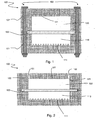
- a filtration device 100 comprises a first block 101 having a cavity which is a first chamber 110, a second block 102 also having a cavity which constitutes a second chamber 102, and a filter membrane 130 positioned between the first chamber 110 and the second chamber 120 and adjacent to each of the first and second chambers 110 , 120.
- these two chambers can receive a fluid to be filtered or a service fluid.
- the membrane 130 allows a material transport from one fluid to another by concentration difference or by pressure difference between the first and second chamber, or by any other known filtration cause of the man of the art.
- the first and second blocks 101, 102 may consist of glass, silica or, for example, polymers such as polymethyl methacrylate (PMMA) or polydimethylsiloxane (PDMS), or a mixture of these. this. PDMS has the advantage of being porous to oxygen.
- the two blocks can be made of the same material, or in different materials.
- the second chamber 120 is intended to receive a circulating fluid.
- the device 100 comprises a first opening 122 and a second opening 123 to allow the passage of a fluid. It further has an upper wall 121.
- membrane means a wall separating two media.
- a membrane has a porosity dependent on the size of its pores.
- the membrane separates the first chamber 110 and the second chamber 120 and defines a single closed space in complementarity with each of these chambers 110, 120.
- the membrane in the absence of pressure difference between the two chambers 110, 120, the membrane has no point of contact with the lower wall 111 of the first chamber 110, nor with the upper wall 121 of the second chamber 120.
- the first opening 122 (respectively the second opening 123) may be a fluid inlet in the second chamber 120 (respectively a fluid outlet of the second chamber 120) or a fluid outlet.
- the second chamber 120 (respectively a fluid inlet in the second chamber 120) depending on the direction of the current provided in the chamber 120.
- the first chamber 110 has a bottom wall 111 preferably having a substantially rectangular shape, which defines a length and a width.
- the length and the width of the bottom wall can respectively measure 13.25 mm and 11.23 mm
- the horizontal is defined as parallel to the bottom wall 111 and the vertical as orthogonal to the wall 111 and directed from the wall 111 to the membrane 130.
- the bottom wall 111 is horizontal and located in below the membrane 130, itself located below the upper wall 121.
- d1 direction of length of the lower wall 111 we note
- the first chamber 110 is for receiving a cell culture.
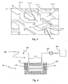
- the bottom wall 111 has a set of microstructures represented in three-dimensions on the figure 3 . These microstructures have been developed by the Applicant and have already been the subject, in their form, of a thesis report: "Development and characterization of a cell chip for the screening of toxic agents”.
- all surface of the bottom wall 111 is understood to mean the area that the bottom wall 111 would have if the microstructures were projected on the wall 111 in the vertical direction. This is the surface of the rectangle formed by the wall 111.
- Micromurs 111.3 have arrow-shaped portions and straight portions, and extend the entire length of the bottom wall 111.
- a micromur 111.3 defines microchamber 111.0 at its arrow-shaped portions in complementarity with another micromur 111.3, and microchannels 111.2 at its straight portions in complementarity with microplots 111.4, as shown in FIG. figure 2 .
- Each microplot 111.4 defines two microchannels located on either side of the microplot, each in complementarity with a micromur.
- the lower wall 111 of the first chamber 110 thus comprises periodic lines in its direction d1 in length, over its entire width.
- Each line comprises an alternation of microchannels 111.0 and microchannels 111.2, two lines being separated by a 111.3 micromur.
- each line may comprise 9 micro-chambers 111.0 and 8 pads 111.4 - each corresponding to two microchannels 111.2 - alternately, the lower wall 111 comprising a total of 15 lines.
- Such a device has on the bottom wall 111 a geometry favorable to the development of cells, particularly compared to flat culture devices such as Petri dishes.
- the microstructures allow a three-dimensional organization of the cells, provided they are fed with nutrient fluid containing elements necessary for the development of the cells, in particular oxygen or glucose.
- the device according to the first aspect of the invention allows a supply of cells without a nutrient fluid flow is required in the first chamber. Indeed, by disposing a stagnant fluid in the first chamber where the cells are caused to develop, and by circulating a nutrient fluid in the second chamber, the elements necessary for the development of cells (in particular glucose) pass into the fluid stagnant, provided that the membrane 130 is appropriately selected. In particular, it is possible to choose a membrane whose porosity is adapted to let glucose pass.
- the device 100 finds a first application in cell culture. Indeed, a circulating nutrient fluid can tear cells and disintegrate structures which is an obstacle to the development of cells and limits their activity.
- the device 100 described above makes it possible to overcome this difficulty by proposing a solution to the feed without circulation of fluid in direct contact with the cells.
- the circulating fluid pressure in the second chamber can cause a deformation of the membrane 130 which then approaches the lower wall 111.
- the membrane 130 then constitutes a mechanical threat to the developing cells; it may disintegrate the cell structures and tear them off the wall 111.
- microstructures protect cells from this harmful effect. Indeed, even if the membrane 130 comes into contact with the lower wall 111, it would be in contact with micromurs 111.3 and 111.4 microplots, the cells can always develop in microchannels 111.0 and 111.2 microchannels. Thus, the microchannels and microchannels constitute a structure not only favorable to the development of the cells, but also protected in the case where the membrane 130 deforms to the lower wall 111.
- the device 100 thus described can be used in a filtration system according to the second aspect of the invention as shown in FIG. figure 4 .
- the system comprises, in addition to a device 100, a fluid circuit 300 comprising a circulation pipe 310 provided with a circulation means 320.
- "Piping” means a set of one or more pipes. These pipes may be flexible or rigid, and consist of any suitable material known to those skilled in the art.
- the fluid circuit 300 is connected to the first and second openings 122, 123 in the second chamber 120 through respective passages 151 and 152 in the second block 102.
- the circulation means 320 is preferably connected to a reserve 340 in a nutrient medium, and may comprise a liquid pump, a peristaltic pump, a set of valves, for example solenoid valves, or any other suitable means known to the person skilled in the art. art.
- the circuit 300 preferably comprises a discharge 350 for the nutrient fluid after passing through the second chamber 120.
- Such a system according to the second aspect of the invention is not limited to this representation in which the circuit 300 is open, and extends in particular to any system in which the circuit 300 is closed and optionally comprises a regeneration means nutrient fluid.
- the device 100 according to the first aspect of the invention is not limited to the description that has been made so far.
- the device 100 further comprises a fluid inlet 112 and a fluid outlet 113 as shown in FIG. figure 5 .
- the fluid inlet 112 is connected to at least a portion of the microchannels 111.2 via an input network 114.
- the input network 114 comprises successive branches for supplying each of the lines of the lower wall 111 of the first chamber from the fluid inlet 112.
- the fluid is intended to circulate at the microchannels 111.2 and microchannels 111.0, and above the microstructures in the first chamber 110, for example to supply the cells in development.
- the fluid outlet 113 is connected to at least a portion of the microchannels via an output network 115.
- the output network 115 includes successive confluence points for connecting each of the lines of the lower wall 111 of the chamber 110 to the fluid outlet 113.
- the microchannels 111.2 form a network connecting the fluid inlet 112 to each microchamber 111.0 - via the input network 114 - and each microchamber to the fluid outlet 113 - through the output network 115 .
- the microchannels 111.0 preferably comprise an inlet zone 111.5 and an outlet zone 111, 6 to allow the circulation of the fluid substantially in the direction of the length direction of the wall 111.
- a fluid containing molecules to be tested on the cells For example, it is possible to circulate in the chamber 110 a fluid containing molecules to be tested on the cells.
- This application is particularly interesting in the detection of substances that are toxic to humans: human cell tissue, nourished through the membrane by a nutrient fluid circulating in chamber 120 and exposed directly to test molecules in chamber 110, is cultured.
- Another possible application is the mechanical stimulation of cells.
- Certain cells such as endothelial cells, are naturally subject to flow conditions, such as blood. These cells are naturally activated by mechanical friction, which can be reproduced by circulation of the fluid in the first chamber 110.
- the micro-chambers 111.0 have a length dimension and a width dimension with respect to the direction d1 each of between 500 ⁇ m and 550 ⁇ m, preferably 520 ⁇ m.
- the dimensions of the microchannels 111.0 of the filtration device 100 are advantageously 520 ⁇ m ⁇ 520 ⁇ m ⁇ 100 ⁇ m.
- the microchannels 111.2 have, with respect to the direction d1, a length dimension of between 700 ⁇ m and 750 ⁇ m, preferably of 720 ⁇ m, and a width dimension of between 200 ⁇ m and 250 ⁇ m, preferably of 220 ⁇ m.
- the dimensions of the microchannels 111.2 of the device 100 are advantageously 720 ⁇ m ⁇ 220 ⁇ m ⁇ 100 ⁇ m.
- the microchannels 111.2 thus sized facilitate the development of liver cells; they allow in particular the migration of liver organ piece through the microchannel network.
- micromurs 111.3, 111.4 microplots and 111.2 microchannels We also represented on the figure 7 several other dimensions characteristic of micromurs 111.3, 111.4 microplots and 111.2 microchannels for a possible embodiment of the filter device 100 of the first aspect of the invention.
- the micromurs 111.3 comprise angular zones 111.7 on either side of the entry zone 111.5 and of the exit zone 111.6 of at least one chamber 111.0, as shown in FIGS. figures 3 and 7 .
- These angular zones 111.7 have a dimension of width with respect to the direction d1 advantageously between 100 ⁇ m and 120 ⁇ m, preferably 110 ⁇ m. In particular, they have a transverse edge to the direction d1 fluid flow.
- the angular zones 111.7 define, with respect to the direction d1, partially protected zones on either side of the inlet zone 111.5 of said chamber 110, that is to say zones where the circulation of the fluid is brutally slowed down.
- the partially protected areas have, according to this advantageous variant of the first aspect of the invention, a transverse edge in the direction d1 with a width of at least 100 .mu.m.
- hepatic cells are capable of aggregating into a spheroid of large diameter, of the order of 100 .mu.m, a form favorable to good cellular activity.
- culture surface denotes all of these development zones.
- the ratio between the culture surface and the overall surface of the bottom wall 111 is between 90% and 110%. It is preferably equal to 100% to an accuracy of 1%.
- the cultivation surface is 151mm 2 .
- the cultivation area ratio on the overall surface of the bottom wall is, in this example, 101%.
- the microstructures on the bottom wall 111 hardly change the area available for cultivation relative to the overall surface of the bottom wall 111, while allowing three-dimensional development.
- cells may also develop on the upper surfaces of 111.3 micromurs and 111.4 microplots, although such areas are not particularly favorable for three-dimensional development.
- total culture surface is then referred to as the previously defined culture surface to which the upper surfaces of the micromurs 111.3 and the microplots 111.4 are added.
- these upper surfaces are 52.5mm 2 and the total culture area is 203.5mm 2 and the ratio of the total culture area to the overall area of the bottom wall is 137%.
- the culture chamber 110 has a volume and the ratio R2 between the total culture surface and the volume of the culture chamber 110 is between 4 mm -1 and 6 mm -1.
- the cells may be confined and not have enough nutrients distributed by the fluid, which is detrimental to their development.
- the volume of the first chamber 110 is understood to mean the volume available for the passage of the fluid; therefore, the volume occupied by the 111.3 micromurs and the 111.4 microplots is excluded.
- the upper surface 121 of the second chamber 120 also has microstructures.
- These microstructures may have all the advantageous variants of the microstructures detailed hitherto concerning the lower wall 111 of the first chamber 110.
- the microstructures may be of identical dimensions on the lower walls 111 and 121, or of different dimensions. This variant is particularly interesting for an application for cell culture in both chambers
- the membrane 130 is preferably made of flexible material and can thus be slightly deformable as a function of the pressure prevailing in each of the chambers 110, 120. As has been seen previously, the microstructures prevent the membrane 130 from sticking to the walls and protecting the culture cells of a possible contact with the membrane 130.
- the membrane 130 may be hydrophilic or hydrophobic, and will be selected according to the intended application (dialysis, cell culture, etc.).
- a membrane is said to be hydrophilic when there is interaction of the terminal groups with water by hydrogen bonding.
- Hydrophilic membranes like cellulose membranes, have a good diffusion and as they have a low adsorption of proteins, they have a good convection; on the other hand, the biocompatibility is poor. They are used in dialysis to let water and very small solutes.
- Hydrophobic membranes like synthetic ones, have a lower diffusion, but a higher ultrafiltration coefficient because of their porous structure which counteracts the negative effect of protein adsorption; the latter is at the origin of the best biocompatibility. They are often used in haemodiafiltration. The biocompatibility of membranes makes many applications of these membranes with cell culture.
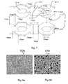
- the membranes can be microstructured with micro-pores microstructures (see Figures 8a and 8b ) but also with micro pores which could also take the form of microchannels or micro pillars or micro geometries, for example geometries as illustrated on the diagram. figure 7 .
- the membrane 130 may be hydrophilic, which limits the adhesion of bacteria and proteins and decreases the resistance of the fluid passage in the pores of the membrane 130.
- the membrane 130 may be hydrophobic, which limits the adhesion of bacteria, facilitates the adhesion of proteins and increases the resistance of the passage of fluid in the pores.
- the membrane 130 is preferably a barrier membrane, that is to say that it only allows small molecules or gases to diffuse and prevents the passage of fluids from a chamber 110, 120, to the other room 120, 110.
- the Figures 8a and 8b show images taken by electron microscope of two examples of membranes 130a, 130b of polyethersulfone filtration with a respective porosity of 40000 Da and 500000 Da.
- the membrane 130 is chosen to allow cell culture on the membrane 130.
- membrane like MDCK or Caco-2 cells.
- the membrane 130 has a surface of the order of cm 2 .
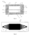
- the filtration device 100 comprises a holding means 160 for holding together the first block 101, the membrane 130 and the second block 102 in this order.
- the means 160 has a locked configuration in which the first block 101 and the membrane 130 are secured, on the other hand the membrane 130 and the second block, and an unlocked configuration, in which the block 101 and the membrane 130 are separable from one another and / or wherein the membrane 130 and the second block 102 are separable from each other.
- the holding means 160 can be switched from the locked configuration to the unlocked configuration and vice versa, for example by action of a user.
- the means 160 may comprise screws passing through their entire height the first block 101, the membrane 130 and the second block 102, as shown in FIG. figure 1 .
- the means 160 may also include cleats, a vise, or any other suitable means known to those skilled in the art.
- Such a holding means 160 has several advantages. It makes it possible to separate the device 100 in its constituents and to be able to reconstruct it afterwards. Thus, chambers 110 and 120, as well as membrane 130, can be accessed without rendering the device 100 unusable.
- This is particularly useful for cleaning the chambers of the molecules to be filtered which have adsorbed on the surfaces and sterilize them, for example by autoclave or by any other suitable cleaning method known to those skilled in the art.
- the membrane 130 can be recovered for analysis, such as transmembrane electrical resistance measurements, the recovery of the membrane to make fluorescent markings on the membranes. cells, impedance analyzes, or any other useful analysis known to those skilled in the art.
- the means 160 also offers the possibility of direct access to the cell culture by avoiding the evacuation of this culture from the device 100 by a fluid which would destroy the culture structure.
- the membrane can be replaced by a new membrane for repetitive experiments without the need for cleaning. It is thus possible to repeat an experiment by changing the membrane 130 while keeping intact the cellular contents of the chambers 110, 120.
- membrane 130 can be transplanted from one device 100 to another and be tested with chambers 110, 120 with different microstructure geometry. This may be useful for characterizing the effect of microstructures on filtration or cell culture on membrane 130.
- the device 100 integrated in the filtration system comprises a fluid inlet 112 and a fluid outlet 113 in the first chamber 110.
- the system comprises a fluid circuit 200 connected to the first chamber 110, similar to the circuit 300 connected to the second chamber 120 that has already been described above.
- the fluid circuit 200 comprises a circulation pipe 210 provided with a circulation means 220 and is connected to the inlet 112 and outlet 113 in the first chamber 110.
- the fluid circuit 200 is connected to the fluid inlet 112 and outlet 113 in the first chamber 110, through respective passages 141 and 142 in the first block 101.
- the circulation means 220 is preferably connected to a reserve 240 in fluid, and may comprise a liquid pump, a peristaltic pump, a set of valves, for example solenoid valves, or any other suitable means known to those skilled in the art. .
- circuit 200 preferably comprises an evacuation 250 for the fluid after passing through the first chamber 110.
- Such a system according to the second aspect of the invention is not limited to this representation in which the circuit 200 is open, and extends in particular to any system in which the circuit 200 is closed and optionally comprises a fluid regeneration means.
- the fluids circulating in the circuits 200 and / or 300 are advantageously temperature-controlled.
- reserves 240 and / or 340 may be arranged in thermostatic baths (not shown).
- any other means of controlling the temperature of the circuits 200 and / or 300 known to those skilled in the art can be envisaged.
- the fluids contained in the lower chamber 110 and upper 120 circulate cocurrently.
- the first opening 122 is a fluid outlet of the second chamber 120 and the second opening 123 is a fluid inlet in the second chamber 120.
- the first opening 122 is a fluid inlet in the second chamber 120 and the second opening 123 is a fluid outlet of the second chamber 120.
- Blood to be treated may circulate in the second chamber 120 and be freed of certain components ordinarily removed by a functional kidney by filtration through the membrane 130.
- a dialysis fluid contained in the first chamber 110 then makes it possible to evacuate the filtered elements and to provide a glucose supply for the patient.
- Such systems can also be used to characterize a filtration membrane 130.
- a diffusion coefficient of a molecule for a given membrane 130 can be evaluated from a physical model and from measurements of the concentrations of the molecule in the first chamber 110 and / or the second chamber 120 as a function of time.
- the co-current system can be used to calibrate the model and estimate the diffusion coefficient, and the countercurrent system can be used to verify the diffusion coefficient, or vice versa.
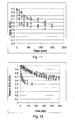
- the experimental results are represented, for an experiment with the membrane with high porosity (of type 8F), by the icons,, ⁇ , and for a experiment with membrane low porosity (of type 1 FPH), by the icons: *, o.
- the circulation circuit 200 advantageously comprises a fluid pressure control means 230 in the first chamber 110
- the circulation circuit 300 advantageously comprises a fluid pressure control means 330 in the second chamber 120
- the two circuits 200, 300 each comprise a pressure control means 230, 330 in their associated chamber 110, 120.
- control means 230 comprises pressure sensors 231, 232 (respectively 331, 332) for detecting a pressure of the fluid in the passages 141, 142 in the first block 101 (respectively 151, 152 in the second block 102) or at the fluid inlet and outlet 112, 113 (respectively at the first and second openings 122, 123).
- the means 230 further comprises actuators 233, 234 (respectively 333, 334) disposed on the pipe 210 (respectively 310) for modifying the pressure at the inlet and at the outlet of the fluid in the first chamber 110 (respectively in the second bedroom 120).
- actuators may be for example solenoid valves controlled by a processing unit (not shown) of data from the pressure sensors, or any other suitable means known to those skilled in the art.
- the pressure checks can be carried out by the processing unit of each control means 230, 330 by stabilizing the pressure around a fixed or variable setpoint value, for example by applying a proportional controller, an integral proportional controller, an open loop (in which case the pressure sensors are not used), or any other suitable control loop known to the person in charge. system control profession.
- control means 230, 330 of the circuits 200, 300 may be similar or different depending on the needs of the application envisaged for the filtration system according to the second aspect of the invention.
- the pressure difference can be maintained at a predetermined value so that the membrane does not adhere to the walls.
- the means 230, 330 make it possible to control the flow conditions in the chambers 110, 120 and the transmembrane flow during the filtration. This makes it possible to regulate filtration parameters for a given solute, such as the rejection rate - that is to say the percentage of dissolved material retained by the membrane - and the diffusion coefficient of the solute through the membrane 130 .
- the means 230, 330 make it possible to carry out repetitive experiments under the same conditions of flow and transmembrane flow.
- a particularly interesting application of this advantageous effect is to test different membranes under similar conditions of experiment, which makes it possible to characterize the properties of the membranes, for example the slope with water - that is to say the hydraulic permeability membranes with pure water - for example through the experiment shown in the figure 14 .
- the fluid flowing in the second chamber 120 is water.
- the first circuit 200 does not include a reserve 240 or a circulation means 220, in which case the short-circuit means 250 is unnecessary.
- the resist 240 and the means 220 are surrounded by a dashed rectangle on the figure 14 .
- the evacuation 350 of the second circuit 300 is blocking for water (for example a closed tap).
- the water circulating in the second chamber through the second opening 152 can only exit the device 100 through the passage 142 of the first block 101, which passage 142 is connected to the discharge 250 of the first circuit 200 by the pipe 210.
- the system according to this variant of the second aspect of the invention is associated with a device 400 for measuring the mass of water, comprising a container 410 connected to the outlet 250, a balance 420 and a treatment unit 430. interaction with the barnacle 420 and for determining the mass of water contained in the container 410 as a function of time. Furthermore, the processing unit receives information from the control means 230, 330 of pressure in the two circuits 200, 300.
- the device 400 is capable of evaluating the mass of filtering water by the membrane 130 as a function of time and of the transmembrane pressure, which makes it possible to determine the slope with water of the membrane 130.
- the experiment was conducted by the Applicant on the membranes 130a and 130b respectively represented on the Figures 8a and 8b .
- the determined water slopes are 8ml / (min.bar.cm 3 ) and 80ml / (min.bar.cm 3 ) respectively.
- Another application is to measure the pressure losses in the first chamber 110 (and in the second chamber 120 if it receives a culture of cells), which losses give an indication of the variations in the number of culture cells in the chamber .
- the invention has many advantages.
- the system according to the second aspect of the invention allows controlled filtration over larger systems.
- the fluid circuits do not experience turbulence and little edge effect, both in the piping and in the chambers of the device according to the first aspect of the invention.
- the pressure control means and the membrane make it possible to maintain uniform parameters (pressure, temperature, composition and concentration of the fluids) so that the observed results can easily be extrapolated to systems with similar parameters.
- the invention constitutes a major step towards in vitro reproduction of phenomena of the human or animal body, as well as towards the realization of artificial organs.
Landscapes
- Health & Medical Sciences (AREA)
- Chemical & Material Sciences (AREA)
- Wood Science & Technology (AREA)
- Organic Chemistry (AREA)
- Life Sciences & Earth Sciences (AREA)
- Engineering & Computer Science (AREA)
- Bioinformatics & Cheminformatics (AREA)
- Zoology (AREA)
- Biomedical Technology (AREA)
- Genetics & Genomics (AREA)
- Microbiology (AREA)
- Biotechnology (AREA)
- Biochemistry (AREA)
- General Engineering & Computer Science (AREA)
- General Health & Medical Sciences (AREA)
- Sustainable Development (AREA)
- Clinical Laboratory Science (AREA)
- Immunology (AREA)
- Dispersion Chemistry (AREA)
- Apparatus Associated With Microorganisms And Enzymes (AREA)
- External Artificial Organs (AREA)
- Separation Using Semi-Permeable Membranes (AREA)
Description
La présente invention concerne la reproduction in vitro de phénomènes de filtration.The present invention relates to in vitro reproduction of filtration phenomena.
Plus précisément, elle concerne un dispositif de filtration pour un bioréacteur avec une membrane séparant deux chambres et un système de filtration mettant en oeuvre un ou plusieurs exemplaires d'un tel dispositif de filtration.More specifically, it relates to a filtration device for a bioreactor with a membrane separating two chambers and a filtration system using one or more examples of such a filtration device.
La greffe demeure actuellement la solution la plus efficace pour le traitement des troubles hépatiques et des dysfonctionnements rénaux. Cependant, l'insuffisance de donneurs oblige les patients en attente d'organe à subir des traitements lourds et réguliers très souvent sources de complications. Un des grands enjeux de l'ingénierie des tissus réside donc dans la mise au point d'organes artificiels capables de se substituer aux organes défaillants ou absents. Les patients verraient alors leurs conditions de vie s'améliorer et le coût des soins diminuer. A cet effet, de nombreuses recherches ont été menées pour reproduire in vitro des phénomènes internes aux organes du corps humain et animal, en particulier les phénomènes de filtration.The transplant is currently the most effective solution for the treatment of liver disorders and kidney dysfunction. However, the insufficiency of donors obliges the patients waiting for organ to undergo heavy and regular treatments very often sources of complications. One of the major challenges of tissue engineering is therefore the development of artificial organs that can replace faulty or absent organs. Patients would then see their living conditions improve and the cost of care decrease. To this end, numerous studies have been conducted to reproduce in vitro phenomena internal to the organs of the human and animal body, in particular the phenomena of filtration.
Pour ce faire, il est nécessaire de disposer d'une part de bioréacteurs reproduisant un environnement favorable au développement et à l'organisation de cellules, proche de celui d'un tissu ou d'un organe animal ou humain, d'autre part de membranes capables de reproduire les phénomènes de filtration, par exemple, la filtration glomérulaire dans le rein. De nombreuses solutions ont été proposées dans l'art antérieur.To do this, it is necessary to have on the one hand bioreactors reproducing an environment favorable to the development and organization of cells, close to that of an animal or human tissue or organ, on the other hand. membranes capable of reproducing filtration phenomena, for example, glomerular filtration in the kidney. Many solutions have been proposed in the prior art.
Le document
L'article « A MEMS-Based Renal Replacement System » publié en juin 2004 décrit une unité de traitement du sang prévue pour une application en hémodialyse continue. L'unité se compose d'un empilement de dispositifs bicouches comprenant chacun un réseau de canaux pour une circulation sanguine et une chambre d'évacuation, les deux réseaux étant en vis-à-vis et séparés par une membrane d'ultrafiltration (voir
Si l'unité présentée permet de mimer efficacement les conditions de transport du sang dans les vaisseaux sanguins, elle n'est pas sans poser des difficultés. En effet, le sang est confiné dans des canaux à section très étroite (hauteur de 35 microns), ce qui limite le débit de sang traité par chaque dispositif de l'entité et peut induire des problèmes d'engorgement des canaux. Les auteurs prévoient pas moins de 100 dispositifs bicouches nécessaires pour réaliser une hémodialyse.If the presented unit can effectively mimic the conditions of blood transport in the blood vessels, it is not without difficulties. Indeed, the blood is confined in channels with very narrow section (height of 35 microns), which limits the flow of blood treated by each device of the entity and can cause canal congestion problems. The authors provide no less than 100 bilayer devices needed to perform hemodialysis.
Le
Le document
Ainsi, une grande variété de dispositifs de filtration in vitro ont été proposés par le passé.Thus, a wide variety of in vitro filtration devices have been proposed in the past.
L'invention propose une filtration d'un type nouveau présentant de nombreux avantages par rapport aux solutions proposées dans l'art antérieur. A cet effet, l'invention propose selon un premier aspect un dispositif de filtration caractérisé en ce qu'il comprend :
- un premier bloc présentant une cavité formant une première chambre comportant une paroi inférieure (présentant un ensemble de microstructures comprenant des micromurs et des microplots, l'ensemble de microstructures définissant, sur la paroi inférieure de la chambre de culture, des microchambres et des microcanaux,
- un deuxième bloc présentant une cavité formant une deuxième chambre, et
- une membrane de filtration,
le premier bloc, la membrane et le deuxième bloc étant agencés de sorte que la membrane soit située entre la première chambre et la deuxième chambre, adjacente à chacune des première et deuxième chambres, - une première ouverture et une deuxième ouverture pour permettre le passage d'un fluide dans la deuxième chambre séparée de la première chambre par la membrane
- a first block having a cavity forming a first chamber having a bottom wall (having a set of microstructures comprising micromurs and microplots, the set of microstructures defining, on the bottom wall of the culture chamber, microchannels and microchannels,
- a second block having a cavity forming a second chamber, and
- a filtration membrane,
the first block, the membrane and the second block being arranged so that the membrane is located between the first chamber and the second chamber, adjacent to each of the first and second chambers, - a first opening and a second opening to allow the passage of a fluid in the second chamber separated from the first chamber by the membrane
Le dispositif de filtration selon le premier aspect de l'invention est avantageusement complété par les caractéristiques suivantes, prises seules ou en une quelconque de leurs combinaisons techniquement possibles :
- une entrée de fluide dans la première chambre connectée à au moins une partie des microcanaux et une sortie de fluide dans la première chambre connectée à au moins une partie des microcanaux sont comprises, les microcanaux formant un réseau reliant l'entrée de fluide à chaque microchambre et chaque microchambre à la sortie de fluide, de sorte à permettre une circulation de fluide dans les microchambres de la première chambre,
- les microchambres présentent une dimension de longueur et une dimension de largeur par rapport à une direction de circulation du fluide chacune comprise entre 500µm et 550µm,
- les microcanaux présentent une dimension de longueur par rapport à une direction de circulation du fluide comprise entre 700µm et 750µm et une dimension de largeur par rapport à une direction de circulation du fluide comprise entre 200µm et 250µm,
- les microchambres comprennent une zone d'entrée et une zone de sortie, les micromurs comprenant des zones anguleuses de part et d'autre de la zone d'entrée et de la zone de sortie d'au moins une chambre, les zones anguleuses présentant une dimension de largeur par rapport à une direction de circulation du fluide comprise entre 100µm et 120µm de sorte à définir, de part et d'autre de la zone d'entrée de ladite chambre des zones partiellement protégées,
- la première chambre présente une surface de culture dans un rapport avec une surface globale de la paroi inférieure compris entre 90% et 110%,
- la première chambre présente une surface de culture dans un rapport avec un volume global disponible de fluide de la première chambre compris entre 4/mm et 6/mm,
- la deuxième chambre comprend une paroi supérieure présentant un ensemble de microstructures identique à celui de la paroi inférieure de la première chambre,
- la membrane est en matériau souple,
- la membrane est en matériau hydrophile,
- la membrane est en matériau hydrophobe,
- la membrane est une membrane barrière,
- la membrane est en matériau adapté pour permettre une culture de cellules sur la membrane,
et - un moyen de maintien présentant une configuration verrouillée dans laquelle sont maintenus solidaires d'une part le premier bloc et la membrane, d'autre part la membrane et le deuxième bloc, et une configuration déverrouillée, dans laquelle le bloc et la membrane sont séparables l'un de l'autre et/ou dans laquelle la membrane et le deuxième bloc sont séparables l'une de l'autre, le moyen de maintien pouvant être basculé de la configuration verrouillée vers la configuration déverrouillée et inversement, est compris.
- a fluid inlet in the first chamber connected to at least a portion of the microchannels and a fluid outlet in the first chamber connected to at least a portion of the microchannels are included, the microchannels forming a network connecting the fluid inlet to each microchamber and each microchamber to the fluid outlet, so as to allow a flow of fluid in the microchamber of the first chamber,
- the microchannels have a length dimension and a width dimension with respect to a fluid flow direction each of between 500 μm and 550 μm,
- the microchannels have a length dimension with respect to a fluid flow direction of between 700 μm and 750 μm and a width dimension with respect to a fluid flow direction of between 200 μm and 250 μm,
- the microchambers comprise an entrance zone and an exit zone, the micromurs comprising angular zones on either side of the entry zone and the exit zone of at least one chamber, the angular zones having a width dimension relative to a direction of fluid flow between 100 μm and 120 μm so as to define, on either side of the inlet zone of said chamber, partially protected zones,
- the first chamber has a culture surface in a ratio with an overall surface of the bottom wall of between 90% and 110%,
- the first chamber has a culture surface in a ratio with an overall available fluid volume of the first chamber of between 4 / mm and 6 / mm,
- the second chamber comprises an upper wall having a set of microstructures identical to that of the lower wall of the first chamber,
- the membrane is of flexible material,
- the membrane is made of hydrophilic material,
- the membrane is made of hydrophobic material,
- the membrane is a barrier membrane,
- the membrane is made of material adapted to allow a cell culture on the membrane,
and - a holding means having a locked configuration in which the first block and the membrane are held together, on the other hand the membrane and the second block, and an unlocked configuration, in which the block and the membrane are separable; of the other and / or in which the membrane and the second block are separable from each other, the holding means can be tilted from the locked configuration to the unlocked configuration and vice versa, is included.
L'invention propose également, selon un deuxième aspect, un système de filtration, caractérisé en ce qu'il comprend
- un dispositif de filtration selon le premier aspect de l'invention, et
- un circuit de fluide comprenant une tuyauterie de circulation munie d'un moyen de circulation et connectée aux première et deuxième ouverture dans la deuxième chambre.
- a filtration device according to the first aspect of the invention, and
- a fluid circuit comprising a circulation pipe provided with a circulation means and connected to the first and second openings in the second chamber.
Le système de filtration selon le deuxième aspect de l'invention est avantageusement complété par les caractéristiques suivantes, prises seules ou en une quelconque de leurs combinaisons techniquement possibles :
- une entrée de fluide dans la première chambre connectée à au moins une partie des microcanaux et une sortie de fluide dans la première chambre connectée à au moins une partie des microcanaux sont comprises, les microcanaux formant un réseau reliant l'entrée de fluide à chaque microchambre et chaque microchambre à la sortie de fluide, de sorte à permettre une circulation de fluide dans les microchambres de la première chambre, le dispositif comprenant en outre un circuit de fluide comprenant une tuyauterie de circulation munie d'un moyen de circulation et connectée aux entrée et sortie de fluide dans la première chambre,
- le premier circuit comprend un moyen de contrôle pour contrôler une pression de fluide dans la première chambre,
et - le deuxième circuit comprend un moyen de contrôle pour contrôler une pression de fluide dans la deuxième chambre.
- a fluid inlet in the first chamber connected to at least a portion of the microchannels and a fluid outlet in the first chamber connected to at least a portion of the microchannels are included, the microchannels forming a network connecting the fluid inlet to each microchamber and each microchamber at the fluid outlet, so as to allow a flow of fluid in the microchamber of the first chamber, the device further comprising a fluid circuit comprising a circulation pipe provided with a circulation means and connected to the inlet and fluid outlet in the first chamber,
- the first circuit comprises a control means for controlling a fluid pressure in the first chamber,
and - the second circuit comprises control means for controlling a fluid pressure in the second chamber.
Selon un troisième aspect, l'invention propose un système de filtration comprenant plusieurs dispositifs de filtration selon le premier aspect de l'intention connectés par des circuits de circulation.According to a third aspect, the invention proposes a filtration system comprising several filtration devices according to the first aspect of the intention connected by circulation circuits.
D'autres caractéristiques, buts et avantages de l'invention ressortiront de la description qui suit, qui est purement illustrative et non limitative, et qui doit être lue en regard des dessins annexés sur lesquels :
- la
figure 1 représente, de manière schématique, un dispositif de filtration en vue de face en coupe selon une réalisation possible du premier aspect de l'invention, - la
figure 2 représente, de manière schématique, un dispositif de filtration en vue de côté en coupe selon une réalisation possible du premier aspect de l'invention, - la
figure 3 représente une vue en perspective tridimensionnelle de microstructures selon une réalisation possible du premier aspect de l'invention, - la
figure 4 représente, de manière schématique un système de filtration en coupe en vue de côté selon une réalisation possible du deuxième aspect de l'invention, - la
figure 5 représente un dispositif de filtration en vue de côté en coupe selon une réalisation possible du premier aspect de l'invention dans laquelle la première chambre est pourvue d'une entrée et d'une sortie de fluide, - la
figure 6 représente de manière schématique un dispositif de filtration en vue de haut en coupe selon une réalisation possible du premier aspect de l'invention dans laquelle la première chambre est pourvue d'un réseau d'entrée et d'un réseau de sortie de fluide, - la
figure 7 représente, de manière schématique en vue de haut, des microstructures de la paroi inférieure de la première chambre, ainsi que des dimensions de ces microstructures selon une réalisation possible du premier aspect de l'invention, - les
figures 8a et 8b représentent des images par microscopie électronique de membranes de porosité différentes selon des réalisations possibles du premier aspect de l'invention, - les
figures 9 et 10 représentent, de manière schématique, un système de filtration en vue de côté en coupe selon des réalisations possibles du deuxième aspect de l'invention, - les
figures 11 et 12 représentent graphiquement une évolution du rapport concentration sur concentration initiale dans la deuxième chambre au cours d'une expérience utilisant un système selon une réalisation possible du deuxième aspect de l'invention, - la
figure 13 représente, de manière schématique, un système de filtration en vue de côté en coupe selon des réalisations possibles du deuxième aspect de l'invention, et - la
figure 14 représente, de manière schématique, une expérience pour caractériser la pente à l'eau d'une membrane, laquelle expérience met en oeuvre un système selon une réalisation possible du deuxième aspect de l'invention.
- the
figure 1 schematically shows a filtration device in sectional front view according to a possible embodiment of the first aspect of the invention, - the
figure 2 schematically represents a filtration device in cross-sectional side view according to one possible embodiment of the first aspect of the invention, - the
figure 3 represents a three-dimensional perspective view of microstructures according to a possible embodiment of the first aspect of the invention, - the
figure 4 schematically shows a sectional filtration system in side view according to a possible embodiment of the second aspect of the invention, - the
figure 5 represents a filtration device with a side view in section according to a possible embodiment of the first aspect of the invention in which the first chamber is provided with an inlet and a fluid outlet, - the
figure 6 schematically represents a filtration device for a sectional view according to a possible embodiment of the first aspect of the invention in which the first chamber is provided with an inlet network and a fluid outlet network, - the
figure 7 represents, schematically in a top view, the microstructures of the lower wall of the first chamber, as well as the dimensions of these microstructures according to a possible embodiment of the first aspect of the invention, - the
Figures 8a and 8b represent images by electron microscopy of membranes of different porosity according to possible embodiments of the first aspect of the invention, - the
Figures 9 and 10 show, schematically, a filtration system with a side view in section according to possible embodiments of the second aspect of the invention, - the
Figures 11 and 12 graphically represent an evolution of the initial concentration concentration ratio in the second chamber during an experiment using a system according to a possible embodiment of the second aspect of the invention, - the
figure 13 schematically represents a filtration system with a side view in section according to possible embodiments of the second aspect of the invention, and - the
figure 14 represents schematically an experiment for characterizing the water slope of a membrane, which experiment implements a system according to a possible embodiment of the second aspect of the invention.
Sur les différentes figures, les éléments similaires portent les mêmes références numériques.In the different figures, similar elements bear the same numerical references.
En référence aux
Ces deux chambres peuvent recevoir un fluide à filtrer ou un fluide de service. Comme on le décrira plus loin, la membrane 130 permet un transport de matière d'un fluide à l'autre par différence dé concentration ou bien par différence de pression entre la première et la deuxième chambre, ou encore par tout autre cause de filtration connue de l'homme de l'art.These two chambers can receive a fluid to be filtered or a service fluid. As will be described below, the
A titre d'exemple non limitatif, les premier et deuxième bloc 101, 102 peuvent être constitués de verre, de silice ou avantageusement de polymères tel que le polyméthacrylate de méthyle (PMMA) ou le polydiméthylsiloxane (PDMS), ou un mélange de ceux-ci. Le PDMS présente l'avantage d'être poreux à l'oxygène. Les deux blocs peuvent être constitués du même matériau, ou bien dans des matériaux différents.By way of nonlimiting example, the first and
La deuxième chambre 120 est destinée à recevoir un fluide en circulation. A cet effet, le dispositif 100 comprend une première ouverture 122 et une deuxième ouverture 123 pour permettre le passage d'un fluide. Elle présente en outre une paroi supérieure 121.The
On entend par « membrane » une paroi séparant deux milieux. Une membrane a une porosité dépendant de la taille de ses pores. En l'occurrence, selon le premier aspect de l'invention, la membrane sépare la première chambre 110 et la deuxième chambre 120 et définit un unique espace clos en complémentarité avec chacune de ces chambres 110, 120. En particulier, en l'absence de différence de pression entre les deux chambres 110, 120, la membrane n'a aucun point de contact avec la paroi inférieure 111 de la première chambre 110, ni avec la paroi supérieure 121 de la deuxième chambre 120.The term "membrane" means a wall separating two media. A membrane has a porosity dependent on the size of its pores. In this case, according to the first aspect of the invention, the membrane separates the
Comme on le décrira en détails plus loin, la première ouverture 122 (respectivement la deuxième ouverture 123) peut être une entrée de fluide dans la deuxième chambre 120 (respectivement une sortie de fluide de la deuxième chambre 120) ou bien une sortie de fluide de la deuxième chambre 120 (respectivement une entrée de fluide dans la deuxième chambre 120) en fonction du sens du courant prévu dans la chambre 120.As will be described in detail below, the first opening 122 (respectively the second opening 123) may be a fluid inlet in the second chamber 120 (respectively a fluid outlet of the second chamber 120) or a fluid outlet. the second chamber 120 (respectively a fluid inlet in the second chamber 120) depending on the direction of the current provided in the
La première chambre 110 présente une paroi inférieure 111 ayant préférentiellement une forme sensiblement rectangulaire, ce qui définit une longueur et une largeur.The
A titre d'exemple non limitatif, la longueur et la largeur de la paroi inférieure peuvent mesurer respectivement 13.25mm et 11.23mmBy way of non-limiting example, the length and the width of the bottom wall can respectively measure 13.25 mm and 11.23 mm
Dans la suite, on définit l'horizontale comme parallèle à la paroi inférieure 111 et la verticale comme orthogonale à la paroi 111 et dirigée de la paroi 111 vers la membrane 130. Ainsi, on dira que la paroi inférieure 111 est horizontale et située en dessous de la membrane 130, elle-même située en dessous de la paroi supérieure 121. Par ailleurs, on note d1 direction de longueur de la paroi inférieure 111.In the following, the horizontal is defined as parallel to the
Ces définitions ont pour but de clarifier la suite du texte et ne doivent en aucun cas être interprétées comme une limitation de la position d'utilisation du dispositif selon le premier aspect de l'invention dans un repère quelconque.These definitions are intended to clarify the rest of the text and should in no way be interpreted as a limitation of the position of use of the device according to the first aspect of the invention in any reference.
La première chambre 110 est destinée à recevoir une culture de cellule. A cet effet, la paroi inférieure 111 présente un ensemble de microstructures représentées en trois-dimensions sur la
Par ailleurs, la Demanderesse a déposé le 23 juin 2009 une demande de brevet
L'ensemble de microstructures comprend :
- des plots 111.4 de dimensions micrométriques désignés par « microplots » dans la suite, et
- des murs 111.3 de dimensions micrométriques désignés par « micromurs » dans la suite.
- 111.4 studs of micrometric dimensions designated by "microplots" in the following, and
- 111.3 walls of micrometric dimensions designated "micromurs" in the following.
On entend par « surface globale » de la paroi inférieure 111 la surface qu'aurait la paroi inférieure 111 si on projetait les microstructures sur la paroi 111 dans la direction verticale. Il s'agit de la surface du rectangle que forme la paroi 111.The term "overall surface" of the
Les micromurs 111.3 présentent des parties en forme de flèche et des parties droites, et s'étendent sur toute la longueur de la paroi inférieure 111.Micromurs 111.3 have arrow-shaped portions and straight portions, and extend the entire length of the
Un micromur 111.3 définit des microchambres 111.0 au niveau de ses parties en forme de flèche en complémentarité avec un autre micromur 111.3, et des microcanaux 111.2 au niveau de ses parties droites en complémentarité avec des microplots 111.4, comme représenté sur la
Chaque microplot 111.4 définit deux microcanaux situés de part et d'autre du microplot, chacun en complémentarité avec un micromur.Each microplot 111.4 defines two microchannels located on either side of the microplot, each in complementarity with a micromur.
La paroi inférieure 111 de la première chambre 110 comprend ainsi des lignes périodiques dans sa direction d1 de longueur, sur toute sa largeur. Chaque ligne comprend une alternance de microchambres 111.0 et de microcanaux 111.2, deux lignes étant séparées par un micromur 111.3.The
A titre d'exemple non limitatif, chaque ligne peut comprendre 9 microchambres 111.0 et 8 plots 111.4 - correspondant chacun à deux microcanaux 111.2 - en alternance, la paroi inférieure 111 comprenant un total de 15 lignes.As a nonlimiting example, each line may comprise 9 micro-chambers 111.0 and 8 pads 111.4 - each corresponding to two microchannels 111.2 - alternately, the
Un tel dispositif présente sur la paroi inférieure 111 une géométrie favorable au développement de cellules, en particulier par rapport aux dispositifs de culture plans comme les boites de Pétri. Les microstructures permettent une organisation des cellules en trois dimensions, à condition de les alimenter en fluide nutritif contenant des éléments nécessaires au développement des cellules, en particulier de l'oxygène ou du glucose.Such a device has on the bottom wall 111 a geometry favorable to the development of cells, particularly compared to flat culture devices such as Petri dishes. The microstructures allow a three-dimensional organization of the cells, provided they are fed with nutrient fluid containing elements necessary for the development of the cells, in particular oxygen or glucose.
A cet effet, le dispositif selon le premier aspect de l'invention permet une alimentation des cellules sans qu'une circulation de fluide nutritif soit nécessaire dans la première chambre. En effet, en disposant un fluide stagnant dans la première chambre où les cellules sont amenées à se développer, et en faisant circuler un fluide nutritif dans la deuxième chambre, les éléments nécessaires au développement des cellules (en particulier le glucose) passent dans le fluide stagnant, pour peu que la membrane 130 soit choisie de façon appropriée. En particulier, on peut choisir une membrane dont la porosité est adaptée pour laisser passer le glucose.For this purpose, the device according to the first aspect of the invention allows a supply of cells without a nutrient fluid flow is required in the first chamber. Indeed, by disposing a stagnant fluid in the first chamber where the cells are caused to develop, and by circulating a nutrient fluid in the second chamber, the elements necessary for the development of cells (in particular glucose) pass into the fluid stagnant, provided that the
Ainsi, le dispositif 100 selon le premier aspect de l'invention trouve une première application dans la culture de cellules. En effet, un fluide nutritif en circulation peut arracher des cellules et désagréger les structures ce qui constitue un obstacle au développement de cellules et limite leur activité. Le dispositif 100 décrit ci-dessus permet d'outrepasser cette difficulté en proposant une solution à l'alimentation sans circulation de fluide en contact direct avec les cellules.Thus, the
Toutefois, la pression de fluide en circulation dans la deuxième chambre peut entrainer une déformation de la membrane 130 qui se rapproche alors de la paroi inférieure 111. La membrane 130 constitue alors une menace mécanique pour les cellules en développement ; elle risque de désagréger les structures de cellules et de les arracher de la paroi 111.However, the circulating fluid pressure in the second chamber can cause a deformation of the
Or, les microstructures protègent les cellules de cet effet néfaste. En effet, même si la membrane 130 venait au contact de la paroi inférieure 111, elle serait au contact des micromurs 111.3 et des microplots 111.4, les cellules pouvant toujours se développer dans les microchambres 111.0 et les microcanaux 111.2. Ainsi, les microchambres et les microcanaux constituent une structure non seulement favorable au développement des cellules, mais aussi protégée dans le cas où la membrane 130 se déforme jusqu'à la paroi inférieure 111.However, microstructures protect cells from this harmful effect. Indeed, even if the
Le dispositif 100 ainsi décrit peut être utilisé dans un système de filtration selon le deuxième aspect de l'invention comme on l'a représenté sur la
Le moyen 320 de circulation est préférentiellement relié à une réserve 340 en milieu nutritif, et peut comprendre une pompe liquide, une pompe péristaltique, un jeu de vannes, par exemple des électrovannes, ou tout autre moyen adapté connu de l'homme de l'art.The circulation means 320 is preferably connected to a
En outre, le circuit 300 comprend préférentiellement une évacuation 350 pour le fluide nutritif après passage dans la deuxième chambre 120.In addition, the
Un tel système selon le deuxième aspect de l'invention n'est pas limité à cette représentation dans lequel le circuit 300 est ouvert, et s'étend en particulier à tout système dans lequel le circuit 300 est fermé et comprend optionnellement un moyen de régénération du fluide nutritif.Such a system according to the second aspect of the invention is not limited to this representation in which the
Par ailleurs, le dispositif 100 selon le premier aspect de l'invention n'est pas limité à la description qui en a été faite jusqu'ici. En variante, on prévoit la possibilité de faire circuler un fluide également dans la première chambre 110.Furthermore, the
A cet effet, le dispositif 100 selon le premier aspect de l'invention comprend en outre une entrée 112 de fluide et une sortie 113 de fluide comme représenté sur la
L'entrée 112 de fluide est connectée à au moins une partie des microcanaux 111.2 par l'intermédiaire d'un réseau 114 d'entrée. Le réseau 114 d'entrée comprend des ramifications successives pour alimenter chacune des lignes de la paroi inférieure 111 de la première chambre à partir de l'entrée 112 de fluide.The
Le fluide est destiné à circuler au niveau des microcanaux 111.2 et des microchambres 111.0, et au dessus des microstructures dans la première chambre 110, par exemple pour alimenter les cellules en développement.The fluid is intended to circulate at the microchannels 111.2 and microchannels 111.0, and above the microstructures in the
La sortie 113 de fluide est connectée à au moins une partie des microcanaux par l'intermédiaire d'un réseau 115 de sortie. Le réseau 115 de sortie comprend des points de confluence successifs pour relier chacune des lignes de la paroi inférieure 111 de la chambre 110 à la sortie 113 de fluide. On a représenté sur la
Ainsi, les microcanaux 111.2 forment un réseau reliant l'entrée 112 de fluide à chaque microchambre 111.0 - par l'intermédiaire du réseau 114 d'entrée - et chaque microchambre à la sortie 113 de fluide - par l'intérmédiaire du réseau 115 de sortie. Les microchambres 111.0 comprennent préférentiellement une zone d'entrée 111.5 et une zone de sortie 111.6 pour permettre la circulation du fluide sensiblement dans la direction d1 - direction de longueur de la paroi 111.Thus, the microchannels 111.2 form a network connecting the
On envisage de nombreuses applications du dispositif selon cette variante avantageuse du premier aspect de l'invention.Numerous applications of the device according to this advantageous variant of the first aspect of the invention are contemplated.
Par exemple, on peut prévoir de faire circuler dans la chambre 110 un fluide contenant des molécules à tester sur les cellules. Cette application est particulièrement intéressante dans le dépistage de substances toxiques pour l'être humain : on cultive un tissu cellulaire humain, nourri à travers la membrane par un fluide nutritif circulant dans la chambre 120 et exposé directement à des molécules tests dans la chambre 110.For example, it is possible to circulate in the chamber 110 a fluid containing molecules to be tested on the cells. This application is particularly interesting in the detection of substances that are toxic to humans: human cell tissue, nourished through the membrane by a nutrient fluid circulating in
Par ailleurs, on peut faire circuler dans la chambre 110 un fluide d'évacuation pour éliminer en continu les sécrétions cellulaires.Moreover, it is possible to circulate in the
Une autre application possible est la stimulation mécanique des cellules Certaines cellules, comme les cellules endothéliales, sont naturellement soumises à des conditions découlement, comme le sang. Ces cellules sont naturellement activées par frottement mécanique, ce que l'on peut reproduire par circulation du fluide dans la première chambre 110,Another possible application is the mechanical stimulation of cells. Certain cells, such as endothelial cells, are naturally subject to flow conditions, such as blood. These cells are naturally activated by mechanical friction, which can be reproduced by circulation of the fluid in the
On va maintenant décrire des dimensionnements avantageux des microstructures selon une réalisation possible du premier aspect de l'invention en référence à la
Dans cette variante avantageuse, les microchambres 111.0 présentent une dimension de longueur et une dimension de largeur par rapport à la direction d1 chacune comprise entre 500µm et 550µm, préférentiellement de 520µm. Ainsi, les dimensions des microchambres 111.0 du dispositif de filtration 100 sont avantageusement 520µm x 520µm x 100µm.In this advantageous variant, the micro-chambers 111.0 have a length dimension and a width dimension with respect to the direction d1 each of between 500 μm and 550 μm, preferably 520 μm. Thus, the dimensions of the microchannels 111.0 of the
Ces dimensions sont particulièrement favorables au développement de cellules hépatiques dans les microchambres 111.0.These dimensions are particularly favorable for the development of liver cells in 111.0 micro-chambers.
Avantageusement encore, les microcanaux 111.2 présentent par rapport à la direction d1 une dimension de longueur comprise entre 700µm et 750µm, préférentiellement de 720µm, et une dimension de largeur comprise entre 200µm et 250µm, préférentiellement de 220µm. Ainsi, les dimensions des microcanaux 111.2 du dispositif 100 sont avantageusement 720µm x 220µm x 100µm.Advantageously, the microchannels 111.2 have, with respect to the direction d1, a length dimension of between 700 μm and 750 μm, preferably of 720 μm, and a width dimension of between 200 μm and 250 μm, preferably of 220 μm. Thus, the dimensions of the microchannels 111.2 of the
Les microcanaux 111.2 ainsi dimensionnés facilitent le développement de cellules hépatiques ; ils permettent en particulier la migration de morceau d'organe de foie à travers le réseau de microcanaux.The microchannels 111.2 thus sized facilitate the development of liver cells; they allow in particular the migration of liver organ piece through the microchannel network.
On a par ailleurs représenté sur la
Selon une variante avantageuse, les micromurs 111.3 comprennent des zones anguleuses 111.7 de part et d'autre de la zone d'entrée 111.5 et de la zone de sortie 111.6 d'au moins une chambre 111.0, comme représenté sur les
Ces zones anguleuses 111.7 présentent une dimension de largeur par rapport à la direction d1 avantageusement comprises entre 100µm et 120µm, préférentiellement de 110µm. En particulier, elles présentent une arête transversale à la direction d1 de circulation du fluide. Les zones anguleuses 111.7 définissent, par rapport à la direction d1, des zones partiellement protégées de part et d'autre de la zone d'entrée 111.5 de ladite chambre 110, c'est-à-dire des zones où la circulation du fluide est brutalement ralentie.These angular zones 111.7 have a dimension of width with respect to the direction d1 advantageously between 100 μm and 120 μm, preferably 110 μm. In particular, they have a transverse edge to the direction d1 fluid flow. The angular zones 111.7 define, with respect to the direction d1, partially protected zones on either side of the inlet zone 111.5 of said
Ainsi, les cellules se développant dans de telles zones partiellement protégées sont peu susceptibles d'être arrachées par le fluide circulant dans la microchambre 111.0.Thus, cells developing in such partially protected areas are unlikely to be torn off by the fluid flowing in microchamber 111.0.
Naturellement, l'étendue d'une zone où les cellules sont protégées d'un arrachement par le fluide dépend des conditions de circulation, en particulier du débit et du cisaillementNaturally, the extent of an area where the cells are protected from being wrenched by the fluid depends on the traffic conditions, in particular flow and shear.
Néanmoins, les zones partiellement protégées présentent, selon cette variante avantageuse du premier aspect de l'invention, une arête transversale à la direction d1 d'une largeur d'au moins 100µm.However, the partially protected areas have, according to this advantageous variant of the first aspect of the invention, a transverse edge in the direction d1 with a width of at least 100 .mu.m.
Elles permettent ainsi une agrégation des cellules au niveau de coins 111.8 de la microchambre 111.0 disposés transversalement de part et d'autre et en aval de la zone d'entrée 111.5 par rapport à la direction d1. En particulier, des cellules hépatiques sont susceptibles de s'agréger en sphéroïde de diamètre important, de l'ordre de 100µm, forme favorable à une bonne activité cellulaire.They thus allow aggregation of the cells at the corners 111.8 of the microchamber 111.0 arranged transversely on either side and downstream of the input zone 111.5 with respect to the direction d1. In particular, hepatic cells are capable of aggregating into a spheroid of large diameter, of the order of 100 .mu.m, a form favorable to good cellular activity.
De manière générale, le réseau de microcanaux permet aux cellules de se développer et de s'agréger en structures tridimensionnelles au niveau de zones de développement, à savoir :
- la partie de la paroi inférieure 111 au niveau des microchambres 111.0,
- la partie de la paroi inférieure 111 au niveau des microcanaux 111.2,
- les parois latérales des micromurs 111.3, et
- les parois latérales des microplots 111.4.
- the part of the
lower wall 111 at the microchamber 111.0, - the part of the
lower wall 111 at the microchannels 111.2, - the sidewalls of micromurs 111.3, and
- the side walls of the micropots 111.4.
On désigne par « surface de culture » l'ensemble de ces zones de développement. Avantageusement, le rapport entre la surface de culture et la surface globale de la paroi inférieure 111 est compris entre 90% et 110%. Il est préférentiellement égal à 100% à une précision d'1% près.The term "culture surface" denotes all of these development zones. Advantageously, the ratio between the culture surface and the overall surface of the
A titre d'exemple numérique non limitatif, la surface de culture peut être décomposée de la manière suivante (pour une surface globale de la paroi inférieure de 149mm2) :
- surface de la paroi inférieure au niveau des microchambres 111.0 et des microcanaux 111.2 : 96.5 mm2,
- surface des parois latérales des micromurs 111.3 : 36.5mm2
- surface des parois latérales des microplots 111.4 : 18mm2,
- surface of the lower wall at the microchamber level 111.0 and microchannels 111.2: 96.5 mm 2 ,
- surface of the sidewalls of the micromurs 111.3: 36.5mm 2
- surface of the side walls of the microplots 111.4: 18mm 2 ,
La surface de culture est donc de 151mm2.The cultivation surface is 151mm 2 .
Le rapport de surface de culture sur la surface globale de la paroi inférieure est donc, dans cet exemple, de 101%.The cultivation area ratio on the overall surface of the bottom wall is, in this example, 101%.
Ainsi, les microstructures sur la paroi inférieure 111 ne modifient presque pas la surface disponible pour la culture par rapport à la surface globale de la paroi inférieure 111, tout en permettant un développement tridimensionnel.Thus, the microstructures on the
En outre, des cellules peuvent aussi se développer sur les surfaces supérieures des micromurs 111.3 et des microplots 111.4, bien que de telles zones ne soient pas particulièrement favorables au développement tridimensionnel.In addition, cells may also develop on the upper surfaces of 111.3 micromurs and 111.4 microplots, although such areas are not particularly favorable for three-dimensional development.
On appelle alors « surface de culture totale » la surface de culture définie précédemment à laquelle on ajoute les surfaces supérieures des micromurs 111.3 et des microplots 111.4.The so-called "total culture surface" is then referred to as the previously defined culture surface to which the upper surfaces of the micromurs 111.3 and the microplots 111.4 are added.
Dans l'exemple numérique précédent, ces surfaces supérieures sont de 52.5mm2 et la surface de culture totale est de 203.5mm2 et le rapport entre la surface de culture totale et la surface globale de la paroi inférieure est de 137%.In the above numerical example, these upper surfaces are 52.5mm 2 and the total culture area is 203.5mm 2 and the ratio of the total culture area to the overall area of the bottom wall is 137%.
Avantageusement encore, la chambre 110 de culture présente un volume et le rapport R2 entre la surface de culture totale et le volume de la chambre 110 de culture est compris entre 4mm-1 et 6mm-1 Advantageously, the
Si le volume est trop faible par rapport à la surface de culture totale (R2 > 6 mm-1) les cellules risquent d'être confinées et de ne pas disposer d'assez de nutriments distribués par le fluide, ce qui est néfaste à leur développement.If the volume is too small relative to the total culture surface (R2> 6 mm -1 ) the cells may be confined and not have enough nutrients distributed by the fluid, which is detrimental to their development.
Par ailleurs, un volume trop important par rapport à la surface de culture totale (R2 < 4 mm-1), n'est pas intéressant ; il est en effet préférable de disposer de dispositifs miniaturisés.Moreover, a volume that is too large relative to the total culture surface (R2 <4 mm -1 ) is not interesting; it is indeed preferable to have miniaturized devices.
On entend par volume de la première chambre 110 le volume disponible pour le passage du fluide ; on exclut donc le volume occupé par les micromurs 111.3 et les microplots 111.4.The volume of the
En reprenant les valeurs de l'exemple numérique précédent, et pour une hauteur de chambre de 0.2mm, on peut déterminer le volume de la chambre 110 de culture : 149 x 0.2 - 52.5 x 0.1 = 24.55mm3 By taking the values of the previous numerical example, and for a chamber height of 0.2 mm, it is possible to determine the volume of the culture chamber 110: 149 x 0.2 - 52.5 x 0.1 = 24.55 mm 3
Le rapport entre surface de culture totale et volume de la première chambre 110 est alors de 203.5mm2 /24.55mm3 = 8.29mm-1.The ratio between the total cultivation area and the volume of the
Avantageusement, la surface supérieure 121 de la deuxième chambre 120 présente elle-aussi des microstructures. Ces microstructures peuvent présenter toutes les variantes avantageuses des microstructures détaillées jusqu'ici concernant la paroi inférieure 111 de la première chambre 110. Les microstructures peuvent être de dimensions identiques sur les parois inférieure 111 et supérieure 121, ou bien de dimensions différentes. Cette variante est particulièrement intéressante pour une application en vue d'une culture de cellules dans les deux chambresAdvantageously, the
On va maintenant décrire plus en détail différentes caractéristiques de la membrane 130 envisagées dans le cadre de l'invention.We will now describe in more detail different characteristics of the
La membrane 130 est de préférence en matériau souple et peut ainsi être légèrement déformable en fonction de la pression régnant dans chacune des chambres 110, 120. Comme on l'a vu précédemment, les microstructures empêchent la membrane 130 de coller aux parois et protègent les cellules de culture d'un éventuel contact avec la membrane 130.The
La membrane 130 peut être hydrophile ou hydrophobe, et sera sélectionnée en fonction de l'application visée (dialyse, culture cellulaire, ...)..The
Une membrane est dite hydrophile lorsqu'il y a interaction des groupements terminaux avec l'eau par liaison hydrogène. Les membranes hydrophiles, comme les membranes cellulosiques, ont une bonne diffusion et comme elles ont une faible adsorption des protéines, elles ont une bonne convection; par contre la biocompatibilité est médiocre. Elles sont utilisées en dialyse pour laisser passer l'eau et les très petits solutés.A membrane is said to be hydrophilic when there is interaction of the terminal groups with water by hydrogen bonding. Hydrophilic membranes, like cellulose membranes, have a good diffusion and as they have a low adsorption of proteins, they have a good convection; on the other hand, the biocompatibility is poor. They are used in dialysis to let water and very small solutes.
Les membranes hydrophobes, comme les synthétiques, ont une diffusion plus faible, mais un coefficient d'ultrafiltration plus élevé du fait de leur structure poreuse qui contrebalance l'effet négatif de l'adsorption des protéines; ce dernier est à l'origine de la meilleure biocompatibilité. Elles sont souvent utilisées en hémodiafiltration. La biocompatibilité des membranes entrain de nombreuses applications de ces membranes avec la culture de cellules.Hydrophobic membranes, like synthetic ones, have a lower diffusion, but a higher ultrafiltration coefficient because of their porous structure which counteracts the negative effect of protein adsorption; the latter is at the origin of the best biocompatibility. They are often used in haemodiafiltration. The biocompatibility of membranes makes many applications of these membranes with cell culture.
Les membranes peuvent être microstructurées avec des microstructures de type micro pores (voir
Avantageusement, la membrane 130 peut être hydrophile, ce qui limite l'adhésion de bactéries et de protéines et diminue la résistance du passage de fluide dans les pores de la membrane 130.Advantageously, the
Alternativement, la membrane 130 peut être hydrophobe, ce qui limite l'adhésion de bactéries, facilite l'adhésion de protéines et augmente la résistance du passage du fluide dans les pores.Alternatively, the
Différentes porosités peuvent être utilisées pour la membrane 130 en fonction de la taille des éléments à filtrer. Selon une variante avantageuse, la membrane 130 est de préférence une membrane barrière, c'est-à-dire qu'elle ne laisse diffuser que les petites molécules ou les gaz et empêche le passage de fluides d'une chambre 110, 120, vers l'autre chambre 120, 110. Les
Selon une réalisation possible de l'invention, la membrane 130 est choisie pour permettre la culture de cellules sur la membrane 130. En particulier, on prévoit de cultiver avantageusement des cellules modèles des barrières biologiques (par exemple barrière intestinale ou barrière encéphalique) sur la membrane, comme des cellules MDCK ou Caco-2.According to a possible embodiment of the invention, the
Préférentiellement, mais non limitativement, la membrane 130 présente une surface de l'ordre du cm2.Preferably, but not exclusively, the
Avantageusement, le dispositif 100 de filtration selon le premier aspect de l'invention comprend un moyen 160 de maintien pour maintenir ensemble le premier bloc 101, la membrane 130 et le deuxième bloc 102 dans cet ordre.Advantageously, the
Le moyen 160 présente une configuration verrouillée dans laquelle sont maintenus solidaires d'une part le premier bloc 101 et la membrane 130, d'autre part la membrane 130 et le deuxième bloc, et une configuration déverrouillée, dans laquelle le bloc 101 et la membrane 130 sont séparables l'un de l'autre et/ou dans laquelle la membrane 130 et le deuxième bloc 102 sont séparables l'une de l'autre.The means 160 has a locked configuration in which the
En outre, le moyen 160 de maintien peut être basculé de la configuration verrouillée vers la configuration déverrouillée et inversement, par exemple par action d'un utilisateur.In addition, the holding means 160 can be switched from the locked configuration to the unlocked configuration and vice versa, for example by action of a user.
Le moyen 160 peut comprendre des vis traversant sur toute leur hauteur le premier bloc 101, la membrane 130 et le deuxième bloc 102, comme on l'a représenté sur la
Un tel moyen 160 de maintien présente plusieurs avantages. Il permet de séparer le dispositif 100 en ses constituants et de pouvoir le reconstruire ensuite. Ainsi, on peut accéder aux chambres 110 et 120, ainsi qu'à la membrane 130, sans rendre le dispositif 100 inutilisable.Such a holding means 160 has several advantages. It makes it possible to separate the
Ceci est tout particulièrement utile pour nettoyer les chambres des molécules à filtrer qui se sont adsorbées sur les surfaces et les stériliser, par exemple par autoclave ou par tout autre procédé de nettoyage adapté connu de l'homme de l'art.This is particularly useful for cleaning the chambers of the molecules to be filtered which have adsorbed on the surfaces and sterilize them, for example by autoclave or by any other suitable cleaning method known to those skilled in the art.
Par ailleurs, on peut récupérer la membrane 130 pour la soumettre à des analyses, comme des mesures de résistance électrique transmembranaire, la récupération de la membrane pour réaliser des marquages fluorescents sur les cellules, des analyses d'impédance, ou toute autre analyse utile connue de l'homme de l'art. Dans le cas d'une membrane recevant une culture de cellules, le moyen 160 offre aussi la possibilité d'accéder directement à la culture de cellules en évitant l'évacuation de cette culture du dispositif 100 par un fluide qui détruirait la structure de culture.Moreover, the
En outre, la membrane peut être remplacée par une nouvelle membrane pour des expériences répétitives sans nécessité de nettoyage. On peut ainsi réitérer une expérience en changeant la membrane 130 tout en gardant intact le contenu cellulaire des chambres 110, 120.In addition, the membrane can be replaced by a new membrane for repetitive experiments without the need for cleaning. It is thus possible to repeat an experiment by changing the
Inversement, une même membrane 130 peut être transplantée d'un dispositif 100 à un autre et faire l'objet d'expériences avec des chambres 110, 120 à géométrie de microstructures différentes. Ceci peut être utile pour caractériser l'effet des microstructures sur la filtration ou sur une culture de cellules sur la membrane 130..Conversely, the
On va maintenant décrire, en regard des
Dans les variantes envisagées ci-dessous, le dispositif 100 intégré dans le système de filtration comprend une entrée 112 de fluide et une sortie 113 de fluide dans la première chambre 110.In the variants envisaged below, the
Le système comprend un circuit 200 de fluide connecté à la première chambre 110, analogue au circuit 300 connecté à la deuxième chambre 120 qu'on a déjà décrit plus haut. Le circuit 200 de fluide comprend une tuyauterie de circulation 210 munie d'un moyen 220 de circulation et est connectée aux entrées 112 et sortie 113 dans la première chambre 110. Le circuit de fluide 200 est relié aux entrée 112 et sortie 113 de fluide dans la première chambre 110, par l'intermédiaire de passages respectifs 141 et 142 dans le premier bloc 101.The system comprises a
Le moyen 220 de circulation est préférentiellement relié à une réserve 240 en fluide, et peut comprendre une pompe liquide, une pompe péristaltique, un jeu de vannes, par exemple des électrovannes, ou tout autre moyen adapté connu de l'homme de l'art.The circulation means 220 is preferably connected to a
En outre, le circuit 200 comprend préférentiellement une évacuation 250 pour le fluide après passage dans la première chambre 110.In addition, the
Un tel système selon le deuxième aspect de l'invention n'est pas limité à cette représentation dans lequel le circuit 200 est ouvert, et s'étend en particulier à tout système dans lequel le circuit 200 est fermé et comprend optionnellement un moyen de régénération du fluide.Such a system according to the second aspect of the invention is not limited to this representation in which the
Par ailleurs, les fluides circulant dans les circuits 200 et/ou 300 sont avantageusement régulés en température. Par exemple, les réserves 240 et/ou 340 peuvent être disposées dans des bains thermostatés (non représentés). Alternativement, ou cumulativement, tout autre moyen de contrôle de la température des circuits 200 et/ou 300 connu de l'homme de l'art peut être envisagé.Moreover, the fluids circulating in the
Dans la variante de réalisation représentée sur la
On a par ailleurs représenté sur la
Les systèmes décrits par les
De tels systèmes peuvent aussi être utilisés pour caractériser une membrane 130 de filtration. On peut par exemple évaluer un coefficient de diffusion d'une molécule pour une membrane 130 donnée à partir d'un modèle physique et de mesures de concentrations de la molécule dans la première chambre 110 et/ou la deuxième chambre 120 en fonction du temps. Le système à co-courant peut être utilisé pour calibrer le modèle et estimer le coefficient de diffusion, et le système à contre-courant peut être utilisé pour vérifier le coefficient de diffusion, ou l'inverse.Such systems can also be used to characterize a
En particulier, la Demanderesse a modélisé l'évolution de la concentration au cours du temps dans la première chambre 110, dans le cas où un fluide à filtrer circule dans la deuxième chambre 120, par les équations suivantes :
- dans le cas d'un écoulement à co-courant (comme sur la
figure 9 ) :
- dans le cas d'un écoulement à contre-courant (comme sur la
figure 10 ) :
où
- C 1(t) représente la concentration dans la première chambre 110 en fonction du temps t,
- L représente la longueur (commune) des première et deuxième chambres 110, 120,
- b représente la largeur (commune) des première et deuxième chambres 110, 120, Qf représente le débit de filtration,
- V 1 représente le volume de la première chambre 110,
- V 2 représente le volume de la deuxième chambre 120,
- C10 représente la concentration initiale dans la première chambre 110,
- C1∝ représente la concentration d'équilibre dans la première chambre 110,
- Dm représente le coefficient de diffusion de la molécule à filtrer pour
la membrane 130, et - δ représente l'épaisseur de la membrane.
- in the case of a co-current flow (as on the
figure 9 ): - in the case of countercurrent flow (as on the
figure 10 ):
or- C 1 ( t ) represents the concentration in the
first chamber 110 as a function of time t, - L represents the length (common) of the first and
second chambers - b represents the (common) width of the first and
second chambers - V 1 represents the volume of the
first chamber 110, - V 2 represents the volume of the
second chamber 120, - C 10 represents the initial concentration in the
first chamber 110, - C 1 α represents the equilibrium concentration in the
first chamber 110, - D m represents the diffusion coefficient of the molecule to be filtered for the
membrane 130, and - δ represents the thickness of the membrane.
- C 1 ( t ) represents the concentration in the
Grace à ces modèles, il est possible de déterminer les valeurs du coefficient de diffusion Dm des molécules testées pour une membrane 130 donnée. Pour cela, on peut par exemple travailler en mode co-courant et mesurer la disparition de la molécule dans la deuxième chambre 120 (et donc son apparition dans la première chambre 110).Thanks to these models, it is possible to determine the values of the diffusion coefficient Dm of the molecules tested for a given
On a représenté sur les
Les résultats expérimentaux sont représentés, pour une expérience avec la membrane à forte porosité (de type 8F), par les icones □ ,Δ, et pour une expérience avec membrane à faible porosité (de type 1 FPH), par les icones: *, o. On fait ensuite une régression du modèle analytique, par exemple par une minimisation aux moindres carrés, ce qui permet d'obtenir expérimentalement les coefficients de diffusion répertoriés (en m2/s) dans le tableau suivant. :
Ainsi plus la molécule est grosse plus le coefficient de diffusion est petit. En outre, plus la membrane est poreuse plus le coefficient de diffusion est important.So the bigger the molecule, the smaller the diffusion coefficient. In addition, the more porous the membrane, the higher the diffusion coefficient.
La validité du coefficient de diffusion a ensuite été prouvée à l'aide du modèle à contre-courant.The validity of the diffusion coefficient was then proved using the countercurrent model.
Ainsi, on peut caractériser une membrane avec un microsystème nécessitant une surface de membrane de l'ordre du cm2. Si nécessaire, les caractéristiques estimées peuvent être extrapolées sur des membranes de taille supérieure.Thus, it is possible to characterize a membrane with a microsystem requiring a membrane surface of the order of cm 2 . If necessary, the estimated characteristics can be extrapolated to larger membranes.
En référence à la
Préférentiellement, mais non limitativement, le moyen 230 de contrôle (respectivement 330) comprend des capteurs de pression 231, 232 (respectivement 331, 332) pour détecter une pression du fluide dans les passages 141, 142 dans le premier bloc 101 (respectivement 151, 152 dans le deuxième bloc 102) ou au niveau des entrée et sortie de fluide 112, 113 (respectivement au niveau des première et deuxième ouvertures 122, 123). Le moyen 230 (respectivement 330) comprend en outre des actionneurs 233, 234 (respectivement 333, 334) disposés sur la tuyauterie 210 (respectivement 310) pour modifier la pression en entrée et en sortie du fluide dans la première chambre 110 (respectivement dans la deuxième chambre 120). Ces actionneurs peuvent être par exemple des électrovannes commandées par une unité de traitement (non représentée) de données en provenance des capteurs de pression, ou tout autre moyen adapté connu de l'homme dé l'art.Preferably, but not exclusively, the control means 230 (respectively 330) comprises
Les contrôles de pression peuvent être effectués par l'unité de traitement de chaque moyen de contrôle 230, 330 en stabilisant la pression autour d'une valeur de consigne fixe ou variable par exemple par application d'un régulateur proportionnel, un régulateur proportionnel intégral, une boucle ouverte (auquel cas les capteurs de pression ne sont pas utilisés), ou tout autre boucle de contrôle adaptée connue par l'homme du métier de contrôle de systèmes.The pressure checks can be carried out by the processing unit of each control means 230, 330 by stabilizing the pressure around a fixed or variable setpoint value, for example by applying a proportional controller, an integral proportional controller, an open loop (in which case the pressure sensors are not used), or any other suitable control loop known to the person in charge. system control profession.
Les moyens de contrôle 230, 330 des circuits 200, 300 peuvent être similaires ou différents selon les besoins de l'application envisagée pour le système de filtration selon le deuxième aspect de l'invention.The control means 230, 330 of the
Ils s'avèrent très utiles pour la surveillance de certains paramètres au cours de la filtration comme le taux de rejet ou le coefficient de diffusion. Les conditions de débits et le flux transmembranaire peuvent ainsi être étroitement contrôlés.They are very useful for monitoring certain parameters during filtration such as rejection rate or diffusion coefficient. The flow conditions and the transmembrane flow can thus be closely controlled.
La différence de pression peut être maintenue à une valeur déterminée de telle sorte que la membrane ne vienne pas adhérer sur les parois.The pressure difference can be maintained at a predetermined value so that the membrane does not adhere to the walls.
Par ailleurs, les moyens 230, 330 permettent de contrôler les conditions de débits dans les chambres 110, 120 et le flux transmembranaire lors de la filtration. Ceci permet de réguler des paramètres de la filtration pour un soluté donné, tels que le taux de rejet - c'est-à-dire le pourcentage de matière dissoute retenue par la membrane - et le coefficient de diffusion du soluté à travers la membrane 130.Moreover, the
Ainsi, les moyens 230, 330 permettent de procéder à des expériences répétitives dans les mêmes conditions de débit et de flux transmembranaire.Thus, the
Une application particulièrement intéressante de cet effet avantageux est de tester différentes membranes dans des conditions similaires d'expérience, ce qui permet de caractériser les propriétés des membranes, par exemple la pente à l'eau- c'est-à-dire la perméabilité hydraulique des membranes à l'eau pure -, par exemple via l'expérience représentée sur la
Dans cette expérience, le fluide circulant dans la deuxième chambre 120 est de l'eau. Il n'y a pas de culture de cellules dans la première chambre 110, première chambre 110 qui est en outre isolée de la réserve 240 et du moyen 220 de circulation par un moyen de court-circuit 250 du premier circuit 200. Alternativement, on peut envisager dans cet exemple que le premier circuit 200 ne comprend pas de réserve 240 ni de moyen 220 de circulation, auquel cas le moyen de court-circuit 250 est non nécessaire. Pour représenter ceci, la réserve 240 et le moyen 220 sont entourés d'un rectangle en traits pointillés sur la
En outre, l'évacuation 350 du deuxième circuit 300 est bloquante pour eau (par exemple un robinet fermé). Ainsi, l'eau circulant dans la deuxième chambre par la deuxième ouverture 152 ne peut sortir du dispositif 100 que par le passage 142 du premier bloc 101, lequel passage 142 est relié à l'évacuation 250 du premier circuit 200 par la tuyauterie 210.In addition, the
Par ailleurs, le système selon cette variante du deuxième aspect de l'invention est associée à un dispositif 400 de mesure de masse d'eau, comprenant un conteneur 410 relié à l'évacuation 250, une balance 420 et une unité de traitement 430 en interaction avec la balane 420 et destinée à déterminer la masse d'eau contenue dans le conteneur 410 en fonction du temps. Par ailleurs, l'unité de traitement reçoit des informations des moyens de contrôle 230, 330 de pression dans les deux circuits 200, 300.Furthermore, the system according to this variant of the second aspect of the invention is associated with a
Ainsi, le dispositif 400 est capable d'évaluer la masse d'eau filtrant par la membrane 130 en fonction du temps et de la pression transmembranaire, ce qui permet de déterminer la pente à l'eau de la membrane 130.Thus, the
L'expérience a été menée par la Demanderesse sur les membranes 130a et 130b représentées respectivement sur les
Une autre application est de mesurer les pertes de charges dans la première chambre 110 (et dans la deuxième chambre 120 si elle reçoit une culture de cellules), lesquelles pertes de charges donnent une indication sur les variations du nombre de cellules de culture dans la chambre.Another application is to measure the pressure losses in the first chamber 110 (and in the
Enfin, il est possible d'envisager la mise en série de plusieurs dispositifs 1.00 de filtration permettant ainsi de reproduire intégralement les étapes de fonctionnement d'un rein, chaque dispositif reproduisant une fonction particulière. Plus généralement, on peut utiliser plusieurs dispositifs 100 en série pour reproduire les interactions entre un fluide et différents tissus cellulaires dans l'organisme.Finally, it is possible to consider putting in series several filtration devices 1.00 thus making it possible to fully reproduce the operating steps of a kidney, each device reproducing a particular function. More generally,
L'invention présente de nombreux avantages. Le système selon le deuxième aspect de l'invention permet une filtration contrôlée par rapport à de plus gros systèmes. Les circuits de fluides ne connaissent pas de turbulence et que peu d'effet de bords, que ce soit dans la tuyauterie comme dans les chambres du dispositif selon le premier aspect de l'invention. Les moyens de contrôle de pression et la membrane permettent de maintenir des paramètres uniformes (pression, température composition et concentration des fluides) de sorte que les résultats observés sont facilement extrapolables vers des systèmes à paramètres analogues. Ainsi, l'invention constitue un grand pas vers la reproduction in vitro de phénomènes du corps humain ou animal, ainsi que vers la réalisation d'organes artificiels.The invention has many advantages. The system according to the second aspect of the invention allows controlled filtration over larger systems. The fluid circuits do not experience turbulence and little edge effect, both in the piping and in the chambers of the device according to the first aspect of the invention. The pressure control means and the membrane make it possible to maintain uniform parameters (pressure, temperature, composition and concentration of the fluids) so that the observed results can easily be extrapolated to systems with similar parameters. Thus, the invention constitutes a major step towards in vitro reproduction of phenomena of the human or animal body, as well as towards the realization of artificial organs.
Claims (15)
- Filtration device (100) characterised in that it comprises:- a first block (101) having a cavity forming a first chamber (110) comprising a bottom wall (111) having a set of microstructures comprising microwalls (111.3) and micro-contacts (111.4); with the set of microstructures defining, on the bottom wall (111) of the culture chamber, micro-bumps (111.0) and micro-channels (111.2),- a second block (102) having a cavity forming a second chamber (120), and- a filtration membrane (130),
with the first block (101), the membrane (130) and the second block (102) being arranged such that the membrane (130) is located between the first chamber (110) and the second chamber (120), adjacent to each of the first and second chambers (110, 120),- a first opening (122) and a second opening (123) for enabling a first fluid to pass into the second chamber (120) which is separated from the first chamber (110) by the membrane (130) - Device (100) as claimed in the preceding claim, further comprising:- a fluid inlet (112) in the first chamber (110) connected to at least one portion of the micro-channels (111.2),- a fluid outlet (113) in the first chamber (110) connected to at least one portion of the micro-channels (111.2),
with the micro-channels forming a network connecting the fluid inlet (112) to each micro-chamber (111.0) and each micro-chamber (111.0) to the fluid outlet (113), in such a way as to allow for a circulation of fluid in the micro-chambers (111.0) of the first chamber (110). - Filtration device (100) according to one of the preceding claims, wherein the micro-chambers (111.0) have a measurement of length and a measurement of width with respect to a direction of circulation of the fluid each between 500µm and 550µm.
- Filtration device (100) according to one of the preceding claims, wherein the micro-channels (111.2) have a measurement of length with respect to a direction of circulation of the fluid between 700µm and 750µm and a measurement of width with respect to a direction of circulation of the fluid between 200µm and 250µm.
- Filtration device (100) according to one of the preceding claims, wherein the micro-chambers (111.0) include an inlet zone (111.5) and an outlet zone (111.6), with the microwalls (111.3) comprising angular zones (117) on either side of the inlet zone (115) and of the outlet zone (116) of at least one chamber (110), with the angular zones (117) having a measurement of length with respect to a direction of circulation of the fluid between 100µm and 120µm in such a way as to define, on either side of the inlet zone (111.5) of said chamber (111.0) partially protected zones.
- Filtration device (100) according to one of the preceding claims, wherein the first chamber (110) has a culture surface in a ratio with a global surface of the bottom wall (111) between 90% and 110%.
- Filtration device (100) according to one of the preceding claims, wherein the first chamber (110) has a culture surface in a ratio with an available global volume of fluid of the first chamber (110) between 4/mm and 6/mm.
- Filtration device (100) according to one of the preceding claims, wherein the second chamber (120) comprises a top wall (121) having a set of microstructures identical to that of the bottom wall (111) of the first chamber (110).
- Filtration device (100) according to one of the preceding claims, wherein the membrane (130) is made of a material suited for allowing a culture of cells on the membrane (130).
- Filtration device (100) according to one of the preceding claims, further comprising a means for maintaining (160) having a locked configuration wherein are maintained integral on one hand the first block (101) and the membrane (130), on the other hand the membrane (130) and the second block, and an unlocked configuration, wherein the block (101) and the membrane (130) can be separated from one another and/or wherein the membrane (130) and the second block (102) can be separated from one another, with the means for maintaining (160) able to be switched from the locked configuration to the unlocked configuration and inversely.
- Filtration system, characterised in that it comprises- a filtration device (100) according to one of claims 1 to 10, and- a fluid circuit (300) comprising a circulation pipe (310) provided with a means for circulation (320) and connected to the first and second openings (122, 123) in the second chamber (120).
- Filtration system as claimed in the preceding claim, wherein the filtration device (100) comprises- a fluid inlet (112) in the first chamber (110) connected to at least one portion of the micro-channels (111.2),- a fluid outlet (113) in the first chamber (110) connected to at least one portion of the micro-channels (111.2).
with the micro-channels forming a network connecting the fluid inlet (112) to each micro-chamber (111.0) and each micro-chamber (111.0) to the fluid outlet (113), in such a way as to allow for a circulation of fluid in the micro-chambers (111.0) of the first chamber (110).
with the device further comprising a fluid circuit (200) comprising a circulation pipe (210) provided with a means for circulation (220) and connected to the fluid inlet (112) and outlet (113) in the first chamber (110). - Filtration system according to one of claims 11 to 12, wherein the first circuit (200) further comprises a means for controlling (230) in order to control a fluid pressure in the first chamber (110).
- Filtration system according to one of claims 11 to 13, wherein the second circuit (300) further comprises a means for controlling (330) in order to control a fluid pressure in the second chamber (120).
- Filtration system characterised in that it comprises several filtration devices (100) according to one of claims 1 to 10 connected in series by circulation circuits.
Applications Claiming Priority (2)
| Application Number | Priority Date | Filing Date | Title |
|---|---|---|---|
| FR0956568A FR2950359B1 (en) | 2009-09-23 | 2009-09-23 | FILTRATION DEVICE AND SYSTEM |
| PCT/EP2010/064082 WO2011036226A2 (en) | 2009-09-23 | 2010-09-23 | Filtration device and system |
Publications (2)
| Publication Number | Publication Date |
|---|---|
| EP2480654A2 EP2480654A2 (en) | 2012-08-01 |
| EP2480654B1 true EP2480654B1 (en) | 2015-06-17 |
Family
ID=42211816
Family Applications (1)
| Application Number | Title | Priority Date | Filing Date |
|---|---|---|---|
| EP10757102.8A Active EP2480654B1 (en) | 2009-09-23 | 2010-09-23 | Filtration device and system |
Country Status (7)
| Country | Link |
|---|---|
| US (2) | US20130005027A1 (en) |
| EP (1) | EP2480654B1 (en) |
| JP (1) | JP5956340B2 (en) |
| CA (1) | CA2774952C (en) |
| FR (1) | FR2950359B1 (en) |
| IL (1) | IL218794A (en) |
| WO (1) | WO2011036226A2 (en) |
Families Citing this family (5)
| Publication number | Priority date | Publication date | Assignee | Title |
|---|---|---|---|---|
| EP2831221A1 (en) * | 2012-03-29 | 2015-02-04 | The Arizona Board Of Regents On Behalf Of The University of Arizona | Cell culture apparatus and culture methods using same |
| KR101807765B1 (en) * | 2012-11-16 | 2017-12-11 | 주식회사 케이티 | System and method for mobile payment |
| EP3400976A1 (en) * | 2017-05-12 | 2018-11-14 | Universitat Rovira i Virgili | Device and method for the preparation of platelet rich plasma |
| JP7483679B2 (en) | 2018-08-14 | 2024-05-15 | ブリストル-マイヤーズ スクイブ カンパニー | Improved protein recovery |
| US20230113710A1 (en) * | 2021-10-08 | 2023-04-13 | Shanghai Ruiyu Biotech Co., Ltd. | Culture devices |
Family Cites Families (14)
| Publication number | Priority date | Publication date | Assignee | Title |
|---|---|---|---|---|
| US5763266A (en) * | 1989-06-15 | 1998-06-09 | The Regents Of The University Of Michigan | Methods, compositions and devices for maintaining and growing human stem and/or hematopoietics cells |
| JPH05292990A (en) * | 1992-04-09 | 1993-11-09 | Tabai Espec Corp | Production of substance and cell culture vessel therefor |
| US5801055A (en) * | 1997-09-10 | 1998-09-01 | Becton Dickinson And Company | Multi-well culture dish assembly |
| US6197575B1 (en) * | 1998-03-18 | 2001-03-06 | Massachusetts Institute Of Technology | Vascularized perfused microtissue/micro-organ arrays |
| US7776021B2 (en) * | 2000-04-28 | 2010-08-17 | The Charles Stark Draper Laboratory | Micromachined bilayer unit for filtration of small molecules |
| SE0004296D0 (en) * | 2000-11-23 | 2000-11-23 | Gyros Ab | Device and method for the controlled heating in micro channel systems |
| CA2479072A1 (en) * | 2002-03-12 | 2003-12-18 | Surface Logix, Inc. | Assay device that analyzes the absorption, metabolism, permeability and/or toxicity of a candidate compound |
| US20040018611A1 (en) * | 2002-07-23 | 2004-01-29 | Ward Michael Dennis | Microfluidic devices for high gradient magnetic separation |
| US8129179B2 (en) * | 2002-08-27 | 2012-03-06 | Vanderbilt University | Bioreactors with an array of chambers and a common feed line |
| US6878271B2 (en) * | 2002-09-09 | 2005-04-12 | Cytonome, Inc. | Implementation of microfluidic components in a microfluidic system |
| US7048856B2 (en) * | 2002-09-11 | 2006-05-23 | Regents Of The University Of Michigan | Ultrafiltration membrane, device, bioartificial organ, and methods |
| US7476326B2 (en) * | 2003-09-26 | 2009-01-13 | Ahn Chong H | On-chip sample preparation for whole blood analysis |
| US8003380B2 (en) * | 2006-01-04 | 2011-08-23 | Agency For Science, Technology And Research | High throughput cell-based assays fabricated with integrated silicon and cell culture technologies |
| KR20100020524A (en) * | 2007-06-18 | 2010-02-22 | 가부시키가이샤 구라레 | Cell culture container and cell culture method |
-
2009
- 2009-09-23 FR FR0956568A patent/FR2950359B1/en active Active
-
2010
- 2010-09-23 US US13/497,247 patent/US20130005027A1/en not_active Abandoned
- 2010-09-23 CA CA2774952A patent/CA2774952C/en active Active
- 2010-09-23 JP JP2012530264A patent/JP5956340B2/en active Active
- 2010-09-23 WO PCT/EP2010/064082 patent/WO2011036226A2/en active Application Filing
- 2010-09-23 EP EP10757102.8A patent/EP2480654B1/en active Active
-
2012
- 2012-03-22 IL IL218794A patent/IL218794A/en active IP Right Grant
-
2016
- 2016-12-16 US US15/382,437 patent/US20170096629A1/en not_active Abandoned
Also Published As
| Publication number | Publication date |
|---|---|
| EP2480654A2 (en) | 2012-08-01 |
| WO2011036226A2 (en) | 2011-03-31 |
| US20170096629A1 (en) | 2017-04-06 |
| JP5956340B2 (en) | 2016-07-27 |
| FR2950359A1 (en) | 2011-03-25 |
| CA2774952A1 (en) | 2011-03-31 |
| WO2011036226A3 (en) | 2011-12-29 |
| US20130005027A1 (en) | 2013-01-03 |
| IL218794A0 (en) | 2012-06-28 |
| FR2950359B1 (en) | 2011-12-02 |
| IL218794A (en) | 2015-05-31 |
| JP2013505029A (en) | 2013-02-14 |
| CA2774952C (en) | 2018-05-15 |
Similar Documents
| Publication | Publication Date | Title |
|---|---|---|
| US10730016B2 (en) | Ultrafiltration membrane, device, bioartificial organ, and related methods | |
| BE1009306A5 (en) | Bioreactor. | |
| EP2480654B1 (en) | Filtration device and system | |
| Desai et al. | Nanoporous anti-fouling silicon membranes for biosensor applications | |
| EP2119503B1 (en) | Microfluid system and method for sorting clusters of cells and continuously encapsulating them once they are sorted | |
| US20060213836A1 (en) | Ultrafiltration membrane,device, bioartificial organ, and methods | |
| FR2690926A1 (en) | Variable volume reactor type device and cell culture method. | |
| WO2002006441A1 (en) | Cell culture chamber and bioreactor for extracorporeal culture of animal cells | |
| JP2014501603A (en) | Filter assembly for fixing | |
| EP2705132A1 (en) | Method for harvesting microalgae, and device for implementing said method | |
| EP1206522A1 (en) | Biological device, especially for cell culture | |
| WO2010149567A2 (en) | Bioreactor for culturing cells | |
| FR2957086A1 (en) | Box useful in a system for dynamic cell culture or for seeding cells, comprises a well, a microstructured chamber for dynamic cell culture, a microsystem, and connectors attached to an interface of the microsystem | |
| FR3045664A1 (en) | MEMBRANE FOR RECONSTRUCTED FABRIC COMPRISING PORES OF SEVERAL DIAMETERS | |
| EP3805362A1 (en) | Method for producing a vascular structure | |
| Vogel | Design, fabrication and testing of support structures for biomimetic water filters | |
| WO2024017663A1 (en) | Assembling and growing cellular objects on a contact structure by means of axial and transverse acoustic radiation forces | |
| WO2012066055A1 (en) | Device for analyzing the effects of at least one parameter relating to a volatile substance |
Legal Events
| Date | Code | Title | Description |
|---|---|---|---|
| PUAI | Public reference made under article 153(3) epc to a published international application that has entered the european phase |
Free format text: ORIGINAL CODE: 0009012 |
|
| 17P | Request for examination filed |
Effective date: 20120329 |
|
| AK | Designated contracting states |
Kind code of ref document: A2 Designated state(s): AL AT BE BG CH CY CZ DE DK EE ES FI FR GB GR HR HU IE IS IT LI LT LU LV MC MK MT NL NO PL PT RO SE SI SK SM TR |
|
| DAX | Request for extension of the european patent (deleted) | ||
| GRAP | Despatch of communication of intention to grant a patent |
Free format text: ORIGINAL CODE: EPIDOSNIGR1 |
|
| INTG | Intention to grant announced |
Effective date: 20140924 |
|
| GRAP | Despatch of communication of intention to grant a patent |
Free format text: ORIGINAL CODE: EPIDOSNIGR1 |
|
| INTG | Intention to grant announced |
Effective date: 20150312 |
|
| GRAS | Grant fee paid |
Free format text: ORIGINAL CODE: EPIDOSNIGR3 |
|
| GRAA | (expected) grant |
Free format text: ORIGINAL CODE: 0009210 |
|
| AK | Designated contracting states |
Kind code of ref document: B1 Designated state(s): AL AT BE BG CH CY CZ DE DK EE ES FI FR GB GR HR HU IE IS IT LI LT LU LV MC MK MT NL NO PL PT RO SE SI SK SM TR |
|
| REG | Reference to a national code |
Ref country code: GB Ref legal event code: FG4D Free format text: NOT ENGLISH |
|
| REG | Reference to a national code |
Ref country code: CH Ref legal event code: EP |
|
| REG | Reference to a national code |
Ref country code: AT Ref legal event code: REF Ref document number: 731956 Country of ref document: AT Kind code of ref document: T Effective date: 20150715 |
|
| REG | Reference to a national code |
Ref country code: IE Ref legal event code: FG4D Free format text: LANGUAGE OF EP DOCUMENT: FRENCH |
|
| REG | Reference to a national code |
Ref country code: DE Ref legal event code: R096 Ref document number: 602010025312 Country of ref document: DE |
|
| REG | Reference to a national code |
Ref country code: CH Ref legal event code: NV Representative=s name: MICHELI AND CIE SA, CH |
|
| PG25 | Lapsed in a contracting state [announced via postgrant information from national office to epo] |
Ref country code: NO Free format text: LAPSE BECAUSE OF FAILURE TO SUBMIT A TRANSLATION OF THE DESCRIPTION OR TO PAY THE FEE WITHIN THE PRESCRIBED TIME-LIMIT Effective date: 20150917 Ref country code: FI Free format text: LAPSE BECAUSE OF FAILURE TO SUBMIT A TRANSLATION OF THE DESCRIPTION OR TO PAY THE FEE WITHIN THE PRESCRIBED TIME-LIMIT Effective date: 20150617 Ref country code: LT Free format text: LAPSE BECAUSE OF FAILURE TO SUBMIT A TRANSLATION OF THE DESCRIPTION OR TO PAY THE FEE WITHIN THE PRESCRIBED TIME-LIMIT Effective date: 20150617 Ref country code: HR Free format text: LAPSE BECAUSE OF FAILURE TO SUBMIT A TRANSLATION OF THE DESCRIPTION OR TO PAY THE FEE WITHIN THE PRESCRIBED TIME-LIMIT Effective date: 20150617 |
|
| REG | Reference to a national code |
Ref country code: AT Ref legal event code: MK05 Ref document number: 731956 Country of ref document: AT Kind code of ref document: T Effective date: 20150617 |
|
| REG | Reference to a national code |
Ref country code: LT Ref legal event code: MG4D Ref country code: NL Ref legal event code: MP Effective date: 20150617 |
|
| PG25 | Lapsed in a contracting state [announced via postgrant information from national office to epo] |
Ref country code: GR Free format text: LAPSE BECAUSE OF FAILURE TO SUBMIT A TRANSLATION OF THE DESCRIPTION OR TO PAY THE FEE WITHIN THE PRESCRIBED TIME-LIMIT Effective date: 20150918 Ref country code: LV Free format text: LAPSE BECAUSE OF FAILURE TO SUBMIT A TRANSLATION OF THE DESCRIPTION OR TO PAY THE FEE WITHIN THE PRESCRIBED TIME-LIMIT Effective date: 20150617 Ref country code: BG Free format text: LAPSE BECAUSE OF FAILURE TO SUBMIT A TRANSLATION OF THE DESCRIPTION OR TO PAY THE FEE WITHIN THE PRESCRIBED TIME-LIMIT Effective date: 20150917 |
|
| PG25 | Lapsed in a contracting state [announced via postgrant information from national office to epo] |
Ref country code: EE Free format text: LAPSE BECAUSE OF FAILURE TO SUBMIT A TRANSLATION OF THE DESCRIPTION OR TO PAY THE FEE WITHIN THE PRESCRIBED TIME-LIMIT Effective date: 20150617 |
|
| PG25 | Lapsed in a contracting state [announced via postgrant information from national office to epo] |
Ref country code: RO Free format text: LAPSE BECAUSE OF NON-PAYMENT OF DUE FEES Effective date: 20150617 Ref country code: AT Free format text: LAPSE BECAUSE OF FAILURE TO SUBMIT A TRANSLATION OF THE DESCRIPTION OR TO PAY THE FEE WITHIN THE PRESCRIBED TIME-LIMIT Effective date: 20150617 Ref country code: CZ Free format text: LAPSE BECAUSE OF FAILURE TO SUBMIT A TRANSLATION OF THE DESCRIPTION OR TO PAY THE FEE WITHIN THE PRESCRIBED TIME-LIMIT Effective date: 20150617 Ref country code: PL Free format text: LAPSE BECAUSE OF FAILURE TO SUBMIT A TRANSLATION OF THE DESCRIPTION OR TO PAY THE FEE WITHIN THE PRESCRIBED TIME-LIMIT Effective date: 20150617 Ref country code: PT Free format text: LAPSE BECAUSE OF FAILURE TO SUBMIT A TRANSLATION OF THE DESCRIPTION OR TO PAY THE FEE WITHIN THE PRESCRIBED TIME-LIMIT Effective date: 20151019 Ref country code: ES Free format text: LAPSE BECAUSE OF FAILURE TO SUBMIT A TRANSLATION OF THE DESCRIPTION OR TO PAY THE FEE WITHIN THE PRESCRIBED TIME-LIMIT Effective date: 20150617 Ref country code: SK Free format text: LAPSE BECAUSE OF FAILURE TO SUBMIT A TRANSLATION OF THE DESCRIPTION OR TO PAY THE FEE WITHIN THE PRESCRIBED TIME-LIMIT Effective date: 20150617 Ref country code: IS Free format text: LAPSE BECAUSE OF FAILURE TO SUBMIT A TRANSLATION OF THE DESCRIPTION OR TO PAY THE FEE WITHIN THE PRESCRIBED TIME-LIMIT Effective date: 20151017 |
|
| REG | Reference to a national code |
Ref country code: DE Ref legal event code: R097 Ref document number: 602010025312 Country of ref document: DE |
|
| PLBE | No opposition filed within time limit |
Free format text: ORIGINAL CODE: 0009261 |
|
| STAA | Information on the status of an ep patent application or granted ep patent |
Free format text: STATUS: NO OPPOSITION FILED WITHIN TIME LIMIT |
|
| PG25 | Lapsed in a contracting state [announced via postgrant information from national office to epo] |
Ref country code: IT Free format text: LAPSE BECAUSE OF FAILURE TO SUBMIT A TRANSLATION OF THE DESCRIPTION OR TO PAY THE FEE WITHIN THE PRESCRIBED TIME-LIMIT Effective date: 20150617 Ref country code: LU Free format text: LAPSE BECAUSE OF FAILURE TO SUBMIT A TRANSLATION OF THE DESCRIPTION OR TO PAY THE FEE WITHIN THE PRESCRIBED TIME-LIMIT Effective date: 20150923 Ref country code: MC Free format text: LAPSE BECAUSE OF FAILURE TO SUBMIT A TRANSLATION OF THE DESCRIPTION OR TO PAY THE FEE WITHIN THE PRESCRIBED TIME-LIMIT Effective date: 20150617 Ref country code: DK Free format text: LAPSE BECAUSE OF FAILURE TO SUBMIT A TRANSLATION OF THE DESCRIPTION OR TO PAY THE FEE WITHIN THE PRESCRIBED TIME-LIMIT Effective date: 20150617 |
|
| 26N | No opposition filed |
Effective date: 20160318 |
|
| PG25 | Lapsed in a contracting state [announced via postgrant information from national office to epo] |
Ref country code: SI Free format text: LAPSE BECAUSE OF FAILURE TO SUBMIT A TRANSLATION OF THE DESCRIPTION OR TO PAY THE FEE WITHIN THE PRESCRIBED TIME-LIMIT Effective date: 20150617 |
|
| REG | Reference to a national code |
Ref country code: FR Ref legal event code: PLFP Year of fee payment: 7 |
|
| PG25 | Lapsed in a contracting state [announced via postgrant information from national office to epo] |
Ref country code: MT Free format text: LAPSE BECAUSE OF FAILURE TO SUBMIT A TRANSLATION OF THE DESCRIPTION OR TO PAY THE FEE WITHIN THE PRESCRIBED TIME-LIMIT Effective date: 20150617 |
|
| PG25 | Lapsed in a contracting state [announced via postgrant information from national office to epo] |
Ref country code: HU Free format text: LAPSE BECAUSE OF FAILURE TO SUBMIT A TRANSLATION OF THE DESCRIPTION OR TO PAY THE FEE WITHIN THE PRESCRIBED TIME-LIMIT; INVALID AB INITIO Effective date: 20100923 Ref country code: SM Free format text: LAPSE BECAUSE OF FAILURE TO SUBMIT A TRANSLATION OF THE DESCRIPTION OR TO PAY THE FEE WITHIN THE PRESCRIBED TIME-LIMIT Effective date: 20150617 |
|
| PG25 | Lapsed in a contracting state [announced via postgrant information from national office to epo] |
Ref country code: CY Free format text: LAPSE BECAUSE OF FAILURE TO SUBMIT A TRANSLATION OF THE DESCRIPTION OR TO PAY THE FEE WITHIN THE PRESCRIBED TIME-LIMIT Effective date: 20150617 Ref country code: SE Free format text: LAPSE BECAUSE OF FAILURE TO SUBMIT A TRANSLATION OF THE DESCRIPTION OR TO PAY THE FEE WITHIN THE PRESCRIBED TIME-LIMIT Effective date: 20150617 Ref country code: NL Free format text: LAPSE BECAUSE OF FAILURE TO SUBMIT A TRANSLATION OF THE DESCRIPTION OR TO PAY THE FEE WITHIN THE PRESCRIBED TIME-LIMIT Effective date: 20150617 |
|
| PG25 | Lapsed in a contracting state [announced via postgrant information from national office to epo] |
Ref country code: TR Free format text: LAPSE BECAUSE OF FAILURE TO SUBMIT A TRANSLATION OF THE DESCRIPTION OR TO PAY THE FEE WITHIN THE PRESCRIBED TIME-LIMIT Effective date: 20150617 |
|
| REG | Reference to a national code |
Ref country code: FR Ref legal event code: PLFP Year of fee payment: 8 |
|
| PG25 | Lapsed in a contracting state [announced via postgrant information from national office to epo] |
Ref country code: MK Free format text: LAPSE BECAUSE OF FAILURE TO SUBMIT A TRANSLATION OF THE DESCRIPTION OR TO PAY THE FEE WITHIN THE PRESCRIBED TIME-LIMIT Effective date: 20150617 |
|
| REG | Reference to a national code |
Ref country code: FR Ref legal event code: PLFP Year of fee payment: 9 |
|
| PG25 | Lapsed in a contracting state [announced via postgrant information from national office to epo] |
Ref country code: AL Free format text: LAPSE BECAUSE OF FAILURE TO SUBMIT A TRANSLATION OF THE DESCRIPTION OR TO PAY THE FEE WITHIN THE PRESCRIBED TIME-LIMIT Effective date: 20150617 |
|
| PGFP | Annual fee paid to national office [announced via postgrant information from national office to epo] |
Ref country code: IE Payment date: 20230817 Year of fee payment: 14 Ref country code: GB Payment date: 20230920 Year of fee payment: 14 |
|
| PGFP | Annual fee paid to national office [announced via postgrant information from national office to epo] |
Ref country code: FR Payment date: 20230809 Year of fee payment: 14 Ref country code: DE Payment date: 20230911 Year of fee payment: 14 Ref country code: BE Payment date: 20230914 Year of fee payment: 14 |
|
| PGFP | Annual fee paid to national office [announced via postgrant information from national office to epo] |
Ref country code: CH Payment date: 20231001 Year of fee payment: 14 |